EP2676357B1 - Kühleinrichtung zum kühlen eines wicklungsgeflechts einer elektrischen maschine und verfahren zum nachrüsten der elektrischen maschine mit der kühleinrichtung - Google Patents
Kühleinrichtung zum kühlen eines wicklungsgeflechts einer elektrischen maschine und verfahren zum nachrüsten der elektrischen maschine mit der kühleinrichtung Download PDFInfo
- Publication number
- EP2676357B1 EP2676357B1 EP12712613.4A EP12712613A EP2676357B1 EP 2676357 B1 EP2676357 B1 EP 2676357B1 EP 12712613 A EP12712613 A EP 12712613A EP 2676357 B1 EP2676357 B1 EP 2676357B1
- Authority
- EP
- European Patent Office
- Prior art keywords
- winding
- electrical machine
- braid
- baffle
- winding braid
- Prior art date
- Legal status (The legal status is an assumption and is not a legal conclusion. Google has not performed a legal analysis and makes no representation as to the accuracy of the status listed.)
- Active
Links
Images


Classifications
-
- H—ELECTRICITY
- H02—GENERATION; CONVERSION OR DISTRIBUTION OF ELECTRIC POWER
- H02K—DYNAMO-ELECTRIC MACHINES
- H02K9/00—Arrangements for cooling or ventilating
- H02K9/02—Arrangements for cooling or ventilating by ambient air flowing through the machine
- H02K9/04—Arrangements for cooling or ventilating by ambient air flowing through the machine having means for generating a flow of cooling medium
-
- H—ELECTRICITY
- H02—GENERATION; CONVERSION OR DISTRIBUTION OF ELECTRIC POWER
- H02K—DYNAMO-ELECTRIC MACHINES
- H02K15/00—Processes or apparatus specially adapted for manufacturing, assembling, maintaining or repairing of dynamo-electric machines
-
- H—ELECTRICITY
- H02—GENERATION; CONVERSION OR DISTRIBUTION OF ELECTRIC POWER
- H02K—DYNAMO-ELECTRIC MACHINES
- H02K5/00—Casings; Enclosures; Supports
- H02K5/04—Casings or enclosures characterised by the shape, form or construction thereof
- H02K5/20—Casings or enclosures characterised by the shape, form or construction thereof with channels or ducts for flow of cooling medium
- H02K5/207—Casings or enclosures characterised by the shape, form or construction thereof with channels or ducts for flow of cooling medium with openings in the casing specially adapted for ambient air
-
- H—ELECTRICITY
- H02—GENERATION; CONVERSION OR DISTRIBUTION OF ELECTRIC POWER
- H02K—DYNAMO-ELECTRIC MACHINES
- H02K3/00—Details of windings
- H02K3/04—Windings characterised by the conductor shape, form or construction, e.g. with bar conductors
- H02K3/24—Windings characterised by the conductor shape, form or construction, e.g. with bar conductors with channels or ducts for cooling medium between the conductors
-
- Y—GENERAL TAGGING OF NEW TECHNOLOGICAL DEVELOPMENTS; GENERAL TAGGING OF CROSS-SECTIONAL TECHNOLOGIES SPANNING OVER SEVERAL SECTIONS OF THE IPC; TECHNICAL SUBJECTS COVERED BY FORMER USPC CROSS-REFERENCE ART COLLECTIONS [XRACs] AND DIGESTS
- Y10—TECHNICAL SUBJECTS COVERED BY FORMER USPC
- Y10T—TECHNICAL SUBJECTS COVERED BY FORMER US CLASSIFICATION
- Y10T29/00—Metal working
- Y10T29/49—Method of mechanical manufacture
- Y10T29/49002—Electrical device making
- Y10T29/49009—Dynamoelectric machine
Definitions
- the invention relates to a cooling device for cooling an air-permeable winding braid of an electrical machine and an electrical machine with the cooling device.
- An electric machine such as a generator, has a stator with a stator winding.
- the stator winding is formed by winding conductors, wherein the winding conductor is formed into an air-permeable winding braid.
- the stator is cylindrical, wherein the stator winding has a winding end face.
- air cooling As a cooling device, air cooling is known, which has an axial fan, is conveyed with the cooling air axially into the housing for cooling the stator winding.
- the cooling air flows through the winding mesh, which dissipates heat from the winding mesh due to convection effects.
- a hot spot of the winding braid may occur, whereby the risk exists in the area of the front vertex connection to overload the winding braid thermally.
- the DE 195 49 204 A1 discloses a cooling device for cooling an air-permeable winding braid. Another cooling device for cooling an electric machine is known from DE 3242018 A1 known.
- the object of the invention is to provide a cooling device for cooling an air-permeable winding braid of an electrical machine and an electric machine with the cooling device, wherein the winding braid and thus the electric machine are effectively cooled.
- the electric machine has a stator and the cooling device, wherein the winding head of the stator has the winding braid.
- the winding braid has a front vertex connection and the surface of the guide wall is shaped such that the channel has a cross-sectional minimum in the region of the front vertex connection.
- the method not included in the claims for retrofitting an electric machine with the cooling device comprises the steps of: providing an existing electric machine with a housing, a fan arranged, a cooling air flow substantially perpendicular to a first surface portion of a side of the winding braid bubbles, and a stand, wherein the winding head of the stator has an air-permeable winding braid; Installation in the housing of a profile body with a baffle, wherein in the region of a arranged next to the first surface portion second surface portion of the side of the winding mesh, the baffle is arranged substantially parallel and at a distance from the surface of the second surface portion that in the of the baffle and formed a partial stream of the cooling air flow, so that on the side facing away from one side of the winding mesh of the other the winding mesh penetrating partial flow of the cooling air flow flows backflow-free from the winding braid.
- the cooling air flow conveyed by the fan bounces substantially perpendicularly onto the first surface section of the one side of the winding braid.
- the flow through the winding braid is flow-resistant, whereby in the flow direction through the winding braid a pressure drop is recorded.
- the width of the channel defined by the distance of the baffle to the second surface portion determines the flow rate of the partial flow in the channel.
- the distance between the guide wall and the second surface section and thus the width of the channel is to be selected such that formation of a backflow region is prevented at the other side of the winding braid facing away from one side when the partial flow passing through the winding braid exits.
- the contour of the winding braid facing surface of the guide wall of the contour of the second surface portion of the one side of the winding mesh is modeled.
- the speed level is approximately constant, whereby the heat removal from the winding braid along the channel is substantially uniform.
- the fan has a fan shroud with which the fan is sheathed and in which the cooling air flow is conveyed by the fan, and the guide wall has an inlet profile section which is between the fan shroud and the winding braid facing surface of the baffle is arranged so that a partial flow of the cooling flow is free of charge deflected into the channel of the inlet profile section.
- the cooling air flow is conducted with low loss from the fan shroud to the channel, wherein at the channel entrance a correspondingly advantageous high speed level.
- any turbulence is prevented in the inflow, which would otherwise lead to a reduction of the cooling air flow, whereby the cooling efficiency of the winding mesh would be reduced.
- the cooling device has a profile body, which has the guide wall.
- the profile body is preferably annular.
- the profile body is preferably formed segmented over the circumference.
- the profile body is preferably formed divisible in its axial direction.
- the profile body is preferably made of a plastic having a temperature resistance of over 80 ° C.
- the profile body could be made of a polyurethane foam, which has a temperature resistance up to about 120 ° C.
- the profile body could be made of polyester, wherein the profile body is hollow. The segmented and / or divisible in the axial direction of the profile body is advantageous in terms of its installation.
- the electric machine preferably has a housing with the guide wall.
- the housing is advantageously formed with the guide wall, wherein the guide wall is formed integrally in the housing.
- Preferred dimensions of the electrical machine is a generator.
- the profile body is fastened to the housing.
- a generator 1 has a stator 2, which is equipped with a stator winding, which is formed by an air-permeable winding mesh 3.
- the stator 2 with its stator winding is rotationally symmetrical about the machine axis of the generator 1, wherein the end face of the winding braid 3 has a rotationally symmetrical winding head 4.
- the winding braid 3 is formed by a winding conductor 5 or a plurality of winding wires 5, wherein the winding conductor 5 or the winding wires 5 are wound to the winding braid 3.
- the winding head 4 forms an end face 6 of the winding mesh 3, on which a front vertex connection 7 and an involute 8 of the stator winding are arranged.
- the generator 1 is air-cooled, for which purpose a fan 9 is provided.
- the fan 9 has a rotatable around the machine axis of the generator 1 paddle wheel, which is formed by a plurality of gleichgeformten and equidistant over the circumference Axial blades is formed.
- the axial blades are encased radially on the outside by a fan casing 10, which has a trumpet-shaped inlet 11 upstream of the fan 9.
- the fan shroud 10 Downstream of the fan 9, the fan shroud 10 has a circumferential trailing edge 12, at which the cooling air conveyed by the fan 9 flows.
- the generator 1 has a housing 13 in which the stator 2 is arranged.
- the housing 13 has a housing wall 14 which is arranged adjacent to the end face 6 of the winding braid 3 and is arranged concentrically surrounding it radially outside the ventilator 9.
- the housing wall 14 is designed as a wall arranged around the machine axis of the generator 1, on the inside with screws 15 a profile body 16 is attached.
- the profile body 16 is annular and extends from the housing wall 14 axially and radially in the interior of the housing 13, wherein the profile body 16 between the end face 6 of the winding head 4 and the housing wall 14 is arranged.
- the profile body 16 is provided in the housing 13 for deflecting the conveyed by the fan 9 cooling air, wherein the profile body 16 is made of a plastic having a temperature resistance of about 80 ° C.
- the profile body 16 is shaped so that with him the aerodynamically effective contour of the fan shroud 10 is continued at the trailing edge 12 with an inlet profile section 17 substantially free of transition, immediately after the trailing edge 12 of the fan shroud 10 of the inlet profile section 17 has an inlet edge 18 ,
- the inlet profile section 17 of the profile body 16 extends in the flow direction of the funded by the fan 9 cooling air trumpet-shaped radially outward to the winding head 4, with the inlet profile section 17, a deflection of the cooling air is effected radially outward.
- the profile body 16 has a nose 19, with which the profile body 16 protrudes axially in the direction of the winding head 4 axially furthest.
- the end face 6 of the winding head 4 is arranged radially outside the nose 19.
- first baffle 20 and a second baffle 21 are arranged to extend radially outward.
- the first guide wall 20 and the second guide wall 21 are arranged at an axial distance from the end face 6 and the contour of the end face 6 modeled.
- the front vertex connection 7 is arranged in the radial section of the winding head 4 axially from the involute 8 with a rectangular shape, wherein in the most prominent corner of the rectangular shape, the front vertex connection 7 is arranged.
- the first guide wall 20 which is disposed opposite a first surface portion 36 of the end face 6, and the second guide wall 21, which is arranged opposite a second surface portion 37 of the end face 6, guided around, whereby at the end face 6 and the Channel walls 21, 22 a bypass chamber 22 is formed.
- a first bypass space portion 23 of the bypass space 22 and of the second passage portion 21, a second passage bypass portion 24 of the bypass space 22 is formed.
- the profile body 16 has a rear side 26 which is arranged facing away from the inflow edge 18, the inlet profile section 17, the nose 19, the channel walls 20, 21 and the bypass space sections 23, 24 and the outlet profile 25. At the back 26 of the profile body 16 is fixed to the housing wall 14 with the screws 15.
- the first bypass chamber section 23 defines with its distance from the end face 6 a width 27 and the second bypass chamber section 24 defines with its distance from the end face 6 another width 28.
- the widths 27, 28 thus define the width of the bypass space 22.
- a portion of the total cooling air flow 32 penetrates as a fürstrungungsteilstrom 33 the winding head 4 and the winding braid 3. Due to the fact that the winding braid 3 of the braid-like arrangement of the winding wires 5 is designed to be air-permeable, the penetration partial flow 33 can penetrate the winding braid 3. However, this occurs under the formation of flow losses, whereby the fürdringungsteilstrom 33 is subjected to a pressure drop when flowing through the winding mesh 3. This is accompanied by an increase in the static pressure at the location of the winding head 4, at which the total cooling air flow 32 strikes the winding head 4. As a result, in particular, a bypass partial flow 34 is formed as a partial flow of the total cooling air flow 32, which enters the bypass chamber 22 at the nose 19. Thus, the total cooling air flow 32 divides into the penetration partial flow 33 and the bypass partial flow 34.
- bypass partial flow 34 is guided in the first bypass space section 23 to the front vertex connection 7, whereas in the second bypass chamber section 24, the bypass partial flow 34 flows away from the front vertex connection 7. If the bypass partial flow 34 emerges from the second bypass space section 24, then the bypass partial flow 34 merges with the through-flow partial flow 33 which exits on the side of the coil braid 3 facing away from the front side 6. This combination of the naturaldringungsteilstroms 33 and the Umgehungsteilstroms 34 takes place without backflow, whereby at the winding braid 3 about dead water areas are prevented.
- the width 27 of the first bypass space section 23 and the width 28 of the second bypass space section 24 are selected such that the mass flows of the penetration partial flow 33 and the bypass partial flow 34 are selected such that the combination of these partial flows 33, 34 takes place without backflow. If, for example, the widths 27, 28 were not selected such that the partial flows 33, 34 experience a return-free combination, then a return flow 35 would occur at the winding braid 3. The return flow 35 would represent a Totwasser capable by which the cooling of the winding mesh 3 is obstructed by the total cooling air flow 32.
- the front vertex connection 7 By passing and flowing around in particular the front vertex connection 7 by the bypass partial flow 34 in the bypass space 22, the front vertex connection 7 is effectively cooled.
- the winding mesh 3 is penetrated uniformly by the penetration partial flow 33, since about the absence of the return flow 35, which does not occur according to the invention, a uniform outflow of fürdringungsteilstroms 33 is given by the winding braid 3. As a result, an effective cooling of the winding braid 3 is achieved.
- the profile body 16 is segmented seen over the circumference, wherein according to Fig. 3 to 5 the profile body is formed from eight segments 29.
- the profile body 16 is hollow and the individual segments 29 are formed by segmental shells 30, 31.
- the first segment shell 30 forms the inlet profile section 17, the inflow edge 18, the nose 19, the channel walls 20, 21 and the outlet profile 25.
- the second segment shell 31 forms in particular the back 26. The formation of the profile body 16 with the segments 29, with the Segment shells 30, 31 are formed, facilitates the assembly of the profile body 16 in the housing 13th
Landscapes
- Engineering & Computer Science (AREA)
- Power Engineering (AREA)
- Manufacturing & Machinery (AREA)
- Motor Or Generator Cooling System (AREA)
Description
- Die Erfindung betrifft eine Kühleinrichtung zum Kühlen eines luftdurchlässigen Wicklungsgeflechts einer elektrischen Maschine und eine elektrische Maschine mit der Kühleinrichtung.
- Eine elektrische Maschine, wie beispielsweise ein Generator, weist einen Ständer mit einer Ständerwicklung auf. Herkömmlich ist die Ständerwicklung von Wicklungsleiter gebildet, wobei der Wicklungsleiter zu einem luftdurchlässigen Wicklungsgeflecht gebildet ist. Der Ständer ist zylindrisch ausgebildet, wobei die Ständerwicklung stirnseitig einen Wickelkopf aufweist. Beim Betrieb des Generators entstehen in der Ständerwicklung Stromwärmeverluste, die herkömmlich mittels einer Kühleinrichtung von dem Generator abgeführt werden. Insbesondere besteht die Gefahr einer Überhitzung aufgrund der Stromwärmeverluste im Bereich der Stirnscheitelverbindung des Wickelkopfs, wodurch hohe Anforderungen an die Kühleinrichtung zum Kühlen des Wickelkopfs im Bereich der Stirnscheitelverbindung gestellt sind.
- Als Kühleinrichtung ist eine Luftkühlung bekannt, die einen Axiallüfter aufweist, mit dem Kühlluft axial in das Gehäuse zum Kühlen der Ständerwicklung gefördert wird. Mit der Kühlluft wird das Wicklungsgeflecht durchströmt, wodurch aufgrund von Konvektionseffekten Wärme von dem Wicklungsgeflecht abgeführt wird. Hierbei ist es allerdings problematisch, dass insbesondere im Bereich der Stirnscheitelverbindung ein Heißpunkt des Wicklungsgeflechts auftreten kann, wodurch die Gefahr besteht im Bereich der Stirnscheitelverbindung das Wicklungsgeflecht thermisch zu überlasten.
- Die
DE 195 49 204 A1 offenbart eine Kühleinrichtung zum Kühlen eines luftdurchlässigen Wicklungsgeflechtes. Eine weitere Kühleinrichtung zum Kühlen einer elektrischen Maschine ist aus derDE 3242018 A1 bekannt. - Aufgabe der Erfindung ist es, eine Kühleinrichtung zum Kühlen eines luftdurchlässigen Wicklungsgeflechts einer elektrischen Maschine und eine elektrische Maschine mit der Kühleinrichtung zu schaffen, wobei das Wicklungsgeflecht und somit die elektrische Maschine effektiv gekühlt sind.
- Die erfindungsgemäße Kühleinrichtung zum Kühlen eines luftdurchlässigen Wicklungsgeflechts einer elektrischen Maschine weist eine Leitwand und einen Lüfter auf, der angeordnet ist einen Kühlluftstrom im Wesentlichen senkrecht auf einen ersten Oberflächenabschnitt einer Seite des Wicklungsgeflechts zu blasen, wobei im Bereich eines neben dem ersten Oberflächenabschnitt angeordneten zweiten Oberflächenabschnitts der Seite des Wicklungsgeflechts die Leitwand im Wesentlichen parallel und in einem derartigen Abstand zur Oberfläche des zweiten Oberflächenabschnitts angeordnet ist, dass in dem von der Leitwand und dem zweiten Oberflächenabschnitt gebildeten Kanal ein Teilstrom des Kühlluftstroms ausgebildet ist, so dass an der der einen Seite abgewandten Seite des Wicklungsgeflechts der andere das Wicklungsgeflecht durchdringende Teilstrom des Kühlluftstroms rückströmfrei von dem Wicklungsgeflecht abströmt. Die elektrische Maschine weist einen Ständer und die Kühleinrichtung auf, wobei der Wickelkopf des Ständers das Wicklungsgeflecht aufweist.
- Das Wicklungsgeflecht weist eine Stirnscheitelverbindung auf und die Oberfläche der Leitwand ist derart geformt, dass der Kanal im Bereich der Stirnscheitelverbindung ein Querschnittsminimum hat. Dadurch, dass an der Stirnscheitelverbindung eine hohe thermische Belastung des Wicklungsgeflechts beim Betrieb der elektrischen Maschine herrscht, ist es vorteilhaft, dass der Kühlluftstrom durch den Kanal mit einer durch das Querschnittsminimum erzielten hohen Geschwindigkeit vorbeiströmt, wodurch durch entsprechende Konvektionseffekte die Kühlung des Bereichs der Stirnscheitelverbindung des Wicklungsgeflechts effektiv ist.
- Das nicht von den Ansprüchen umfasste Verfahren zum Nachrüsten einer elektrischen Maschine mit der Kühleinrichtung weist die Schritte auf: Bereitstellen einer bestehenden elektrischen Maschine mit einem Gehäuse, einem Lüfter, der angeordnet ist, einen Kühlluftstrom im Wesentlichen senkrecht auf einen ersten Oberflächenabschnitt einer Seite des Wicklungsgeflechts zu blasen, und einem Ständer, wobei der Wickelkopf des Ständers ein luftdurchlässiges Wicklungsgeflecht aufweist; Einbau in das Gehäuse eines Profilkörpers mit einer Leitwand, wobei im Bereich eines neben dem ersten Oberflächenabschnitt angeordneten zweiten Oberflächenabschnitts der Seite des Wicklungsgeflechts die Leitwand im Wesentlich parallel und in einem derartigen Abstand zur Oberfläche des zweiten Oberflächenabschnitts angeordnet wird, dass in dem von der Leitwand und dem zweiten Oberflächenabschnitt gebildeten Kanal ein Teilstrom des Kühlluftstroms ausgebildet wird, so dass an der der einen Seite abgewandten Seite des Wicklungsgeflechts der andere das Wicklungsgeflecht durchdringende Teilstrom des Kühlluftstroms rückströmfrei von dem Wicklungsgeflecht abströmt.
- Der von dem Lüfter geförderte Kühlluftstrom prallt im Wesentlichen senkrecht auf den ersten Oberflächenabschnitt der einen Seite des Wicklungsgeflechts. Dadurch, dass das Wicklungsgeflecht luftdurchlässig ausgebildet ist, kann ein Teil des Kühlluftstroms das Wicklungsgeflecht durchdringen. Das Durchströmen des Wicklungsgeflechts ist strömungswiderstandsbehaftet, wodurch in Durchströmrichtung über das Wicklungsgeflecht ein Druckabfall zu verzeichnen ist. Beim Aufprallen des Kühlluftstroms auf das Wicklungsgeflecht weicht der eine Teilstrom aus und strömt entlang der Oberfläche des Wicklungsgeflechts, wobei der andere Teilstrom des Kühlstroms durch das Wicklungsgeflecht dringt. Der an der Oberfläche des Wicklungsgeflechts entlangströmende Teilstrom tritt in den Kanal ein und wird von der Leitwand im Wesentlichen parallel zur Oberfläche des zweiten Oberflächenabschnitts des Wicklungsgeflechts geführt. Aufgrund der Kontinuitätsbedingung ist durch die Breite des Kanals, der von dem Abstand der Leitwand zu dem zweiten Oberflächenabschnitt definiert ist, die Strömungsgeschwindigkeit des Teilstroms in dem Kanal bestimmt. Erfindungsgemäß ist der Abstand der Leitwand zu dem zweiten Oberflächenabschnitt und somit die Breite des Kanals so zu wählen, dass sich an der der einen Seite abgewandten anderen Seite des Wicklungsgeflechts beim Austreten des das Wicklungsgeflecht durchdringenden Teilstroms eine Ausbildung eines Rückstromgebiets unterbunden ist. Dies wird dadurch erreicht, dass bei einem entsprechend hohen Geschwindigkeitsniveau und einem entsprechend hohem Massenstrom des einen Teilstroms in dem Kanal der Teilstrom beim Austreten aus dem Kanal eine derart hohe kinetische Energie hat, dass die Ausbildung von einem Rückströmgebiet an der Kühlluftaustrittsseite des Wicklungsgeflechts nicht auftreten kann. Wäre im Gegensatz dazu das Geschwindigkeitsniveau in dem Kanal bzw. der Massenstrom und somit die kinetische Energie des aus dem Kanal austretenden Teilstroms zu gering, so könnten von dem durch das Wicklungsgeflecht austretenden Teilstrom etwa Wirbel ausgebildet und angetrieben werden, die als Totwassergebiete eine Wärmeabfuhr von dem Wicklungsgeflecht durch den Kühlluftstrom behindern. Dadurch, dass aufgrund der erfindungsgemäßen Kühleinrichtung die Ausbildung von Totwassergebieten an dem Wicklungsgeflecht unterbunden ist, ist das Wicklungsgeflecht von der Kühleinrichtung effektiv gekühlt.
- Bevorzugt ist es, dass die Kontur der dem Wicklungsgeflecht zugewandten Oberfläche der Leitwand der Kontur des zweiten Oberflächenabschnitts der einen Seite des Wicklungsgeflechts nachempfunden ist. Dadurch ist über die Strömungslänge in dem Kanal das Geschwindigkeitsniveau in etwa konstant, wodurch die Wärmeabfuhr aus dem Wicklungsgeflecht entlang des Kanals im Wesentlichen gleichförmig ist. Außerdem ist es bevorzugt, dass der Lüfter einen Lüftermantel, mit dem der Lüfter ummantelt ist und in dem der Kühlluftstrom von dem Lüfter gefördert ist, und die Leitwand einen Einlassprofilabschnitt aufweist, der zwischen dem Lüftermantel und der dem Wicklungsgeflecht zugewandten Oberfläche der Leitwand so angeordnet ist, dass der eine Teilstrom des Kühlstroms ablösefrei in den Kanal von dem Einlassprofilabschnitt umgelenkt ist. Dadurch wird der Kühlluftstrom verlustarm von dem Lüftermantel zu dem Kanal geführt, wobei am Kanaleintritt ein entsprechend vorteilhaft hohes Geschwindigkeitsniveau ist. Außerdem sind in dem Zuströmbereich etwaige Verwirbelungen unterbunden, die sonst zu einer Reduzierung des Kühlluftstroms führen würden, wodurch die Effektivität bei der Kühlung des Wicklungsgeflechts herabgesetzt wäre.
- Bevorzugtermaßen weist die Kühleinrichtung einen Profilkörper auf, der die Leitwand aufweist. Der Profilkörper ist bevorzugt ringförmig. Ferner ist der Profilkörper bevorzugt über den Umfang segmentiert ausgebildet. Außerdem ist der Profilkörper in seine Axialrichtung bevorzugt teilbar ausgebildet. Der Profilkörper ist bevorzugt aus einem Kunststoff mit einer Temperaturbeständigkeit von über 80°C hergestellt.
- Bevorzugt könnte der Profilkörper aus einem Polyurethanschaum hergestellt sein, der eine Temperaturbeständigkeit bis ca. 120°C hat. Außerdem könnte der Profilkörper aus Polyester hergestellt sein, wobei der Profilkörper hohl ausgebildet ist. Die segmentierte und/oder in Axialrichtung teilbare Ausführung des Profilkörpers ist hinsichtlich dessen Montage vorteilhaft.
- Die elektrische Maschine weist bevorzugt ein Gehäuse mit der Leitwand auf. Dadurch ist vorteilhaft das Gehäuse mit der Leitwand geformt, wobei die Leitwand in dem Gehäuse integriert ausgebildet ist. Bevorzugtermaßen ist die elektrische Maschine ein Generator. Außerdem ist es bevorzugt, dass beim Verfahren zum Nachrüsten der bestehenden elektrischen Maschine der Profilkörper an dem Gehäuse befestigt wird.
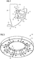
- Im Folgenden wird eine bevorzugte Ausführungsform eines erfindungsgemäßen Generators anhand der beigefügten schematischen Zeichnungen erläutert.
- Es zeigen:
- Figur 1
- einen Längsschnitt im Stirnseitenbereich des Generators,
- Figur 2
- ein Detail eines Profilkörperschnitts aus
Figur 1 , - Figur 3
- eine perspektivische Darstellung des Profilkörpers,
- Figuren 4, 5
- perspektivische Darstellungen von Segmentschalen des Profilkörpers und
- Figur 6
- einen Querschnittsausschnitt des Profilkörpers.
- Wie es aus
Figuren 1 bis 6 ersichtlich ist, weist ein Generator 1 einen Ständer 2 auf, der mit einer Ständerwicklung ausgestattet ist, die von einem luftdurchlässigen Wicklungsgeflecht 3 gebildet ist. Der Ständer 2 mit seiner Ständerwicklung ist rotationssymmetrisch um die Maschinenachse des Generators 1 ausgebildet, wobei stirnseitig das Wicklungsgeflecht 3 einen rotationssymmetrischen Wickelkopf 4 aufweist. Das Wicklungsgeflecht 3 ist von einem Wicklungsleiter 5 oder einer Mehrzahl an Wicklungsdrähten 5 gebildet, wobei der Wicklungsleiter 5 oder die Wicklungsdrähte 5 zu dem Wicklungsgeflecht 3 gewickelt sind. Der Wickelkopf 4 bildet eine Stirnseite 6 des Wicklungsgeflechts 3, an der eine Stirnscheitelverbindung 7 und eine Evolvente 8 der Ständerwicklung angeordnet sind. - Der Generator 1 ist luftgekühlt, wobei hierfür ein Lüfter 9 vorgesehen ist. Der Lüfter 9 weist ein um die Maschinenachse des Generators 1 rotierbares Schaufelrad auf, das von einer Mehrzahl gleichgeformten und über den Umfang äquidistant angeordneten Axialschaufeln gebildet ist. Die Axialschaufeln sind radial außenseitig von einem Lüftermantel 10 ummantelt, der stromauf des Lüfters 9 einen trompetenförmigen Einlauf 11 aufweist. Stromab des Lüfters 9 weist der Lüftermantel 10 eine umlaufende Abströmkante 12 auf, an der die von dem Lüfter 9 geförderte Kühlluft abströmt.
- Der Generator 1 weist ein Gehäuse 13 auf, in dem der Ständer 2 angeordnet ist. Der Stirnseite 6 des Wicklungsgeflechts 3 benachbart angeordnet weist das Gehäuse 13 eine Gehäusewand 14 auf, die radial außerhalb des Lüfters 9 diesen konzentrisch umgebend angeordnet ist. Die Gehäusewand 14 ist als eine um die Maschinenachse des Generators 1 angeordnete Wand ausgebildet, an der innenseitig mit Schrauben 15 ein Profilkörper 16 befestigt ist.
- Der Profilkörper 16 ist ringförmig ausgebildet und erstreckt sich von der Gehäusewand 14 axial und radial im Inneren des Gehäuses 13, wobei der Profilkörper 16 zwischen der Stirnseite 6 des Wickelkopfs 4 und der Gehäusewand 14 angeordnet ist. Der Profilkörper 16 ist in dem Gehäuse 13 zum Umlenken der von dem Lüfter 9 geförderten Kühlluft vorgesehen, wobei der Profilkörper 16 aus einem Kunststoff mit einer Temperaturbeständigkeit von über 80°C hergestellt ist.
- Ferner ist der Profilkörper 16 so geformt, dass mit ihm die aerodynamisch wirksame Kontur des Lüftermantels 10 an der Abströmkante 12 mit einem Einlaufprofilabschnitt 17 im Wesentlichen übergangsfrei fortgesetzt ist, wobei unmittelbar im Anschluss an die Abströmkante 12 des Lüftermantels 10 der Einlaufprofilabschnitt 17 einen Zuströmrand 18 aufweist. Der Einlaufprofilabschnitt 17 des Profilkörpers 16 erstreckt sich in Strömungsrichtung der von dem Lüfter 9 geförderten Kühlluft trompetenförmig radial nach außen zu dem Wickelkopf 4 hin, wobei mit dem Einlaufprofilabschnitt 17 eine Umlenkung der Kühlluft radial nach außen bewirkt ist. An der dem Zuströmrand 18 abgewandten Seite des Einlaufprofilabschnitts 17 weist der Profilkörper 16 eine Nase 19 auf, mit der der Profilkörper 16 in Richtung zu dem Wickelkopf 4 axial am weitesten vorsteht. Die Stirnseite 6 des Wickelkopfs 4 ist radial außerhalb der Nase 19 angeordnet.
- An die Nase 19 sich anschließend und die Kontur des Profilkörpers 16 bildend sind eine erste Leitwand 20 und eine zweite Leitwand 21 radial nach außen verlaufend angeordnet. Die erste Leitwand 20 und die zweite Leitwand 21 sind im Axialabstand von der Stirnseite 6 angeordnet und der Kontur der Stirnseite 6 nachempfunden. Im Radialschnitt steht der Wickelkopf 4 axial von der Evolvente 8 mit einer Rechteckform ab, wobei in der am weitesten vorstehenden Ecke der Rechteckform die Stirnscheitelverbindung 7 angeordnet ist. Um die Stirnscheitelverbindung 7 sind die erste Leitwand 20, die einem ersten Oberflächenabschnitt 36 der Stirnseite 6 gegenüberliegend angeordnet ist, und die zweite Leitwand 21, die einem zweiten Oberflächenabschnitt 37 der Stirnseite 6 gegenüberliegend angeordnet ist, herumgeführt, wodurch sich an der Stirnseite 6 und den Kanalwänden 21, 22 ein Umgehungsraum 22 ausbildet. Von der ersten Leitwand 20 ist ein erster Umgehungsraumabschnitt 23 des Umgehungsraums 22 und von dem zweiten Kanalabschnitt 21 ist ein zweiter Kanalumgehungsabschnitt 24 des Umgehungsraums 22 ausgebildet. Radial nach außen schließt sich an dem Profilkörper 16 ein Auslaufprofil 25 an, das als scheibenförmig und senkrecht zur Maschinenachse des Generators 1 ausgebildet ist. Ferner weist der Profilkörper 16 eine Rückseite 26 auf, die dem Zuströmrand 18, dem Einlaufprofilabschnitt 17, der Nase 19, den Kanalwänden 20, 21 sowie den Umgehungsraumabschnitten 23, 24 und dem Auslaufprofil 25 abgewandt angeordnet ist. An der Rückseite 26 ist der Profilkörper 16 an der Gehäusewand 14 mit den Schrauben 15 befestigt.
- Der erste Umgehungsraumabschnitt 23 definiert mit seinem Abstand von der Stirnseite 6 eine Breite 27 und der zweite Umgehungsraumabschnitt 24 definiert mit seinem Abstand zur Stirnseite 6 eine andere Breite 28. Die Breiten 27, 28 definieren somit die Breite des Umgehungsraums 22. Als Kühlluftstrom wird von dem Lüfter 9 ein Gesamtkühlluftstrom 32 in das Gehäuse 13 gefördert. Der Gesamtkühlluftstrom 32 wird am Einlauf 11 des Kühlermantels 10 angesaugt und strömt an der Abströmkante 12 des Lüftermantels 10 ab. An der Abströmkante 12 unmittelbar angeordnet ist der Zuströmrand 18 des Profilkörpers 16, der in Strömungsrichtung des Gesamtkühlluftstroms 32 in den Einlaufprofilabschnitt 17 übergeht. Dadurch, dass der Einlaufprofilabschnitt 17 nach außen sich aufweitet, wird der Gesamtkühlluftstrom 32 mit einer Radialgeschwindigkeitskomponente versehen.
- Ein Teil des Gesamtkühlluftstroms 32 durchdringt als ein Durchdringungsteilstrom 33 den Wickelkopf 4 und das Wicklungsgeflecht 3. Dadurch, dass das Wicklungsgeflecht 3 von der geflechtartigen Anordnung der Wicklungsdrähte 5 luftdurchlässig ausgebildet ist, kann der Durchdringungsteilstrom 33 das Wicklungsgeflecht 3 durchdringen. Dies geschieht jedoch unter der Entstehung von Strömungsverlusten, wodurch der Durchdringungsteilstrom 33 beim Durchströmen des Wicklungsgeflechts 3 einem Druckabfall unterworfen ist. Damit geht einher eine Erhöhung des statischen Drucks an der Stelle des Wickelkopfs 4, an der der Gesamtkühlluftstrom 32 auf den Wickelkopf 4 trifft. Dadurch bildet sich insbesondere ein Umgehungsteilstrom 34 als ein Teilstrom des Gesamtkühlluftstroms 32 aus, der an der Nase 19 in den Umgehungsraum 22 eintritt. Somit teilt sich der Gesamtkühlluftstrom 32 in den Durchdringungsteilstrom 33 und den Umgehungsteilstrom 34 auf.
- Der Umgehungsteilstrom 34 wird in dem ersten Umgehungsraumabschnitt 23 zu der Stirnscheitelverbindung 7 geführt, wohingegen in dem zweiten Umgehungsraumabschnitt 24 der Umgehungsteilstrom 34 von der Stirnscheitelverbindung 7 abströmt. Tritt der Umgehungsteilstrom 34 aus dem zweiten Umgehungsraumabschnitt 24 aus, so vereinigt sich der Umgehungsteilstrom 34 mit dem durch Durchdringungsteilstrom 33, der an der der Stirnseite 6 abgewandeten Seite des Wicklungsgeflechts 3 austritt. Diese Vereinigung des Durchdringungsteilstroms 33 und des Umgehungsteilstroms 34 geschieht rückströmfrei, wodurch an dem Wicklungsgeflecht 3 etwa Totwassergebiete unterbunden sind.
- Die Breite 27 des ersten Umgehungsraumabschnitts 23 und die Breite 28 des zweiten Umgehungsraumabschnitts 24 sind so gewählt, dass die Massenströme des Durchdringungsteilstroms 33 und des Umgehungsteilstroms 34 so gewählt sind, dass die Vereinigung dieser Teilströme 33, 34 rückströmfrei stattfindet. Wären etwa die Breiten 27, 28 nicht so gewählt, dass die Teilströme 33, 34 eine rückströmfreie Vereinigung erfahren, so würde sich etwa eine Rückströmung 35 am Wicklungsgeflecht 3 einstellen. Die Rückströmung 35 würde ein Totwassergebiet darstellen, durch das die Kühlung des Wicklungsgeflechts 3 von dem Gesamtkühlluftstrom 32 behindert ist.
- Durch das Vorbeiführen und Umströmen insbesondere der Stirnscheitelverbindung 7 durch den Umgehungsteilstrom 34 in dem Umgehungsraum 22 ist die Stirnscheitelverbindung 7 effektiv gekühlt. Außerdem ist das Wicklungsgeflecht 3 von dem Durchdringungsteilstrom 33 gleichmäßig durchdrungen, da etwa von dem Ausbleiben der Rückströmung 35, die erfindungsgemäß nicht auftritt, ein gleichmäßiges Abströmen des Durchdringungsteilstroms 33 von dem Wicklungsgeflecht 3 gegeben ist. Dadurch ist eine effektive Kühlung des Wicklungsgeflechts 3 erzielt.
- Der Profilkörper 16 ist über den Umfang gesehen segmentiert ausgeführt, wobei gemäß
Fig. 3 bis 5 der Profilkörper aus acht Segmenten 29 gebildet ist. Der Profilkörper 16 ist hohl ausgeführt und die einzelnen Segmente 29 sind von Segmentschalen 30, 31 gebildet. Die erste Segmentschale 30 bildet den Einlaufprofilabschnitt 17, den Zuströmrand 18, die Nase 19, die Kanalwände 20, 21 sowie das Auslaufprofil 25. Die zweite Segmentschale 31 bildet insbesondere die Rückseite 26. Die Ausbildung des Profilkörpers 16 mit den Segmenten 29, die mit dem Segmentschalen 30, 31 gebildet sind, erleichtert die Montage des Profilkörpers 16 in das Gehäuse 13.
Claims (11)
- Elektrische Maschine mit einer Kühleinrichtung zum Kühlen eines luftdurchlässigen Wicklungsgeflechts (3) der elektrischen Maschine (1),
mit einer Leitwand (20, 21) und einem Lüfter (9), der angeordnet ist, einen Kühlluftstrom (32) senkrecht auf einen ersten Oberflächenabschnitt (36) der Stirnseite (6) einer Seite des Wicklungsgeflechts (3) zu blasen,
wobei im Bereich eines neben dem ersten Oberflächenabschnitt (37) angeordneten zweiten Oberflächenabschnitts (37) der Stirnseite (6) der Seite des Wicklungsgeflechts (3) die Leitwand (20, 21) parallel und in einem derartigen Abstand (27, 28) zur Oberfläche des zweiten Oberflächenabschnitts (37) der Stirnseite (6) angeordnet ist, dass in dem von der Leitwand (20, 21) und dem zweiten Oberflächenabschnitt (37) der Stirnseite (6) gebildeten Kanal (22) ein Teilstrom (34) des Kühlluftstroms (32) ausgebildet ist, so dass an der der einen Seite abgewandten Seite des Wicklungsgeflechts (3) der andere das Wicklungsgeflecht (3) durchdringende Teilstrom (33) des Kühlluftstroms (32) rückströmfrei von dem Wicklungsgeflecht (3) abströmt,
dadurch gekennzeichnet, dass
das Wicklungsgeflecht (3) eine Stirnscheitelverbindung (7) aufweist und die Oberfläche der Leitwand (20) derart geformt ist, dass der Kanal im Bereich der Stirnscheitelverbindung (7) ein Querschnittsminimum (27) hat. - Elektrische Maschine gemäß Anspruch 1,
wobei die Kontur der dem Wicklungsgeflecht (3) zugewandten Oberfläche der Leitwand (20, 21) der Kontur des zweiten Oberflächenabschnitts (37) der Stirnseite (6) der einen Seite des Wicklungsgeflechts (3) nachempfunden ist. - Elektrische Maschine gemäß Anspruch 1 oder 2,
wobei der Lüfter (9) einen Lüftermantel (10), mit dem der Lüfter (9) ummantelt ist und in dem der Kühlluftstrom (32) von dem Lüfter (9) gefördert ist, und die Leitwand (20, 21) einen Einlaufprofilabschnitt (17) aufweist, der zwischen dem Lüftermantel (10) und der dem Wicklungsgeflecht (3) zugewandten Oberfläche der Leitwand (20, 21) so angeordnet ist, dass der eine Teilstrom (34) des Kühlluftstroms (32) ablösefrei in den Kanal (22) von dem Einlaufprofilabschnitt (17) umgelenkt ist. - Elektrische Maschine gemäß einem der Ansprüche 1 bis 3,
wobei die Kühleinrichtung einen Profilkörper (16) aufweist, der die Leitwand (20, 21) aufweist. - Elektrische Maschine gemäß Anspruch 4,
wobei der Profilkörper (16) ringförmig ist. - Elektrische Maschine gemäß Anspruch 5,
wobei der Profilkörper (16) über den Umfang segmentiert ausgebildet ist. - Elektrische Maschine gemäß Anspruch 5 oder 6,
wobei der Profilkörper (16) in seine Axialrichtung teilbar ausgebildet ist. - Elektrische Maschine gemäß einem der Ansprüche 4 bis 6,
wobei der Profilkörper (16) aus einem Kunststoff mit einer Temperaturbeständigkeit von über 80°C hergestellt ist. - Elektrische Maschine gemäß einem der Ansprüche 1 bis 8 mit einem Ständer
wobei der Wickelkopf (4) des Ständers (2) das Wicklungsgeflecht (3) aufweist. - Elektrische Maschine gemäß Anspruch 9,
wobei die elektrische Maschine (1) ein Gehäuse (13) mit der Leitwand (20, 21) aufweist. - Elektrische Maschine gemäß Anspruch 9 oder 10,
wobei die elektrische Maschine ein Generator (1) ist.
Priority Applications (1)
| Application Number | Priority Date | Filing Date | Title |
|---|---|---|---|
| EP12712613.4A EP2676357B1 (de) | 2011-04-15 | 2012-03-20 | Kühleinrichtung zum kühlen eines wicklungsgeflechts einer elektrischen maschine und verfahren zum nachrüsten der elektrischen maschine mit der kühleinrichtung |
Applications Claiming Priority (3)
| Application Number | Priority Date | Filing Date | Title |
|---|---|---|---|
| EP11162657A EP2512009A1 (de) | 2011-04-15 | 2011-04-15 | Kühleinrichtung zum Kühlen eines Wicklungsgeflechts einer elektrischen Maschine und Verfahren zum Nachrüsten der elektrischen Maschine mit der Kühleinrichtung |
| PCT/EP2012/054860 WO2012139858A2 (de) | 2011-04-15 | 2012-03-20 | Kühleinrichtung zum kühlen eines wicklungsgeflechts einer elektrischen maschine und verfahren zum nachrüsten der elektrischen maschine mit der kühleinrichtung |
| EP12712613.4A EP2676357B1 (de) | 2011-04-15 | 2012-03-20 | Kühleinrichtung zum kühlen eines wicklungsgeflechts einer elektrischen maschine und verfahren zum nachrüsten der elektrischen maschine mit der kühleinrichtung |
Publications (2)
| Publication Number | Publication Date |
|---|---|
| EP2676357A2 EP2676357A2 (de) | 2013-12-25 |
| EP2676357B1 true EP2676357B1 (de) | 2019-10-09 |
Family
ID=44885298
Family Applications (2)
| Application Number | Title | Priority Date | Filing Date |
|---|---|---|---|
| EP11162657A Withdrawn EP2512009A1 (de) | 2011-04-15 | 2011-04-15 | Kühleinrichtung zum Kühlen eines Wicklungsgeflechts einer elektrischen Maschine und Verfahren zum Nachrüsten der elektrischen Maschine mit der Kühleinrichtung |
| EP12712613.4A Active EP2676357B1 (de) | 2011-04-15 | 2012-03-20 | Kühleinrichtung zum kühlen eines wicklungsgeflechts einer elektrischen maschine und verfahren zum nachrüsten der elektrischen maschine mit der kühleinrichtung |
Family Applications Before (1)
| Application Number | Title | Priority Date | Filing Date |
|---|---|---|---|
| EP11162657A Withdrawn EP2512009A1 (de) | 2011-04-15 | 2011-04-15 | Kühleinrichtung zum Kühlen eines Wicklungsgeflechts einer elektrischen Maschine und Verfahren zum Nachrüsten der elektrischen Maschine mit der Kühleinrichtung |
Country Status (4)
| Country | Link |
|---|---|
| US (1) | US9601971B2 (de) |
| EP (2) | EP2512009A1 (de) |
| CN (1) | CN103534910B (de) |
| WO (1) | WO2012139858A2 (de) |
Families Citing this family (2)
| Publication number | Priority date | Publication date | Assignee | Title |
|---|---|---|---|---|
| DE102013207241A1 (de) * | 2013-04-22 | 2014-10-23 | Siemens Aktiengesellschaft | Elektrische Maschine mit einer verbesserten Kühlung des Wickelkopfs |
| WO2021195724A1 (pt) * | 2020-03-30 | 2021-10-07 | Weg Equipamentos Elétricos S/A | Máquina elétrica girante e defletor de ar para máquina elétrica girante |
Family Cites Families (11)
| Publication number | Priority date | Publication date | Assignee | Title |
|---|---|---|---|---|
| JPS5889046A (ja) * | 1981-11-24 | 1983-05-27 | Mitsubishi Electric Corp | 回転電機の冷却装置 |
| CH648439A5 (en) * | 1982-07-15 | 1985-03-15 | Bbc Brown Boveri & Cie | Rotating electrical machine having a stator with radially arranged cooling channels with spacer webs |
| DE19549204C2 (de) * | 1995-12-30 | 1999-08-05 | Bosch Gmbh Robert | Elektrische Maschine, insbesondere Drehstromgenerator |
| US6188153B1 (en) * | 1999-02-18 | 2001-02-13 | General Electric Company | Segmented stator end turn air deflector for force ventilated AC motor |
| US6392326B1 (en) | 2000-12-22 | 2002-05-21 | General Electric Company | Flow-through spaceblocks with deflectors and method for increased electric generator endwinding cooling |
| DE10247310A1 (de) * | 2002-10-10 | 2004-04-22 | Siemens Ag | Belüftung einer elektrischen Maschine |
| US7462962B2 (en) | 2005-06-13 | 2008-12-09 | General Electric Company | Cooling system for an electrical machine with center rotor cooling dusts |
| DE102005045491A1 (de) * | 2005-09-23 | 2007-04-12 | Robert Bosch Gmbh | Elektrische Maschine, insbesondere Drehstromgenerator für Fahrzeuge |
| JP4882346B2 (ja) * | 2005-11-10 | 2012-02-22 | 富士電機株式会社 | 永久磁石を備えた回転電気機械の冷却装置 |
| DE102006029220A1 (de) | 2006-06-26 | 2008-01-10 | Robert Bosch Gmbh | Elektrische Maschine, insbesondere Drehstromgenerator, sowie Kühlungsvorrichtung einer elektrischen Maschine |
| US8269383B2 (en) * | 2010-06-08 | 2012-09-18 | Remy Technologies, Llc | Electric machine cooling system and method |
-
2011
- 2011-04-15 EP EP11162657A patent/EP2512009A1/de not_active Withdrawn
-
2012
- 2012-03-20 US US14/009,384 patent/US9601971B2/en active Active
- 2012-03-20 EP EP12712613.4A patent/EP2676357B1/de active Active
- 2012-03-20 CN CN201280018657.XA patent/CN103534910B/zh active Active
- 2012-03-20 WO PCT/EP2012/054860 patent/WO2012139858A2/de not_active Ceased
Non-Patent Citations (1)
| Title |
|---|
| None * |
Also Published As
| Publication number | Publication date |
|---|---|
| US9601971B2 (en) | 2017-03-21 |
| EP2512009A1 (de) | 2012-10-17 |
| US20140054989A1 (en) | 2014-02-27 |
| EP2676357A2 (de) | 2013-12-25 |
| CN103534910A (zh) | 2014-01-22 |
| WO2012139858A2 (de) | 2012-10-18 |
| WO2012139858A3 (de) | 2013-11-07 |
| CN103534910B (zh) | 2016-03-16 |
Similar Documents
| Publication | Publication Date | Title |
|---|---|---|
| DE102007061597B4 (de) | Elektrische Maschine mit Doppelaxiallüfter | |
| EP2975742B1 (de) | Elektrische Maschine mit verbesserter Kühlung | |
| EP2109207B1 (de) | Flüssigkeitsgekühlte elektrische Maschine sowie Verfahren zur Kühlung einer solchen elektrischen Maschine | |
| EP2798726B1 (de) | Lüftermodul | |
| EP3775565B1 (de) | Kompakter diagonalventilator mit nachleiteinrichtung | |
| DE10355385A1 (de) | Dichtungseinrichtung für das Belüftungssystem eines elektrischen Generators | |
| DE102013020332A1 (de) | Elektrische Maschine, insbesondere Asynchronmaschine | |
| DE102011078791B4 (de) | Geschlossene elektrische Maschine mit Rotorwellenbelüftung | |
| EP3093447B1 (de) | Rotor einer turbine einer gasturbine mit verbesserter kühlluftführung | |
| EP2930827B1 (de) | Elektrische Maschine mit Strömungskühlung | |
| CH323433A (de) | Verfahren und Einrichtung zum Kühlen von elektrischen Leitern einer ganz gekapselten, dynamoelektrischen Maschine | |
| EP2973951B1 (de) | Elektrische maschine mit einer verbesserten kühlung des wickelkopfs | |
| WO2020127379A1 (de) | Elektromotor | |
| EP3033825B1 (de) | Einrichtung zum ablenken von zumindest einem teil eines axial in einem zwischen einem rotor und einem stator einer rotierenden elektrischen maschine angeordneten zwischenraum strömenden kühlfluids | |
| EP2512009A1 (de) | Kühleinrichtung zum Kühlen eines Wicklungsgeflechts einer elektrischen Maschine und Verfahren zum Nachrüsten der elektrischen Maschine mit der Kühleinrichtung | |
| EP3159487B1 (de) | Stator einer turbine einer gasturbine mit verbesserter kühlluftführung | |
| EP2591542A1 (de) | Elektrische maschine | |
| DE3424497A1 (de) | Geblaesediffusor- und kollektoranordnung fuer kuehlsysteme in dynamoelektrischen maschinen | |
| EP2888804B1 (de) | Elektrische maschine und verfahren zum kühlen einer elektrischen maschine | |
| DE4222131C2 (de) | Belüftungseinrichtung für die Druckbelüftung von oberflächenbelüfteten elektrischen Maschinen | |
| EP4264058B1 (de) | Impellermaschine | |
| EP3164931B1 (de) | Elektrodynamische maschine mit kühlströmungskanal | |
| DE102015015650B4 (de) | Kühlsystem eines Elektromotors mit Lüfter | |
| EP3587748B1 (de) | Gehäusestruktur für eine strömungsmaschine, strömungsmaschine und verfahren zum kühlen eines gehäuseabschnitts einer gehäusestruktur einer strömungsmaschine | |
| WO2016058854A1 (de) | Rotorballen für eine rotierende elektrische maschine |
Legal Events
| Date | Code | Title | Description |
|---|---|---|---|
| PUAI | Public reference made under article 153(3) epc to a published international application that has entered the european phase |
Free format text: ORIGINAL CODE: 0009012 |
|
| 17P | Request for examination filed |
Effective date: 20130829 |
|
| AK | Designated contracting states |
Kind code of ref document: A2 Designated state(s): AL AT BE BG CH CY CZ DE DK EE ES FI FR GB GR HR HU IE IS IT LI LT LU LV MC MK MT NL NO PL PT RO RS SE SI SK SM TR |
|
| DAX | Request for extension of the european patent (deleted) | ||
| RAP1 | Party data changed (applicant data changed or rights of an application transferred) |
Owner name: SIEMENS AKTIENGESELLSCHAFT |
|
| STAA | Information on the status of an ep patent application or granted ep patent |
Free format text: STATUS: EXAMINATION IS IN PROGRESS |
|
| 17Q | First examination report despatched |
Effective date: 20180829 |
|
| REG | Reference to a national code |
Ref country code: DE Ref legal event code: R079 Ref document number: 502012015373 Country of ref document: DE Free format text: PREVIOUS MAIN CLASS: H02K0009060000 Ipc: H02K0009040000 |
|
| GRAP | Despatch of communication of intention to grant a patent |
Free format text: ORIGINAL CODE: EPIDOSNIGR1 |
|
| STAA | Information on the status of an ep patent application or granted ep patent |
Free format text: STATUS: GRANT OF PATENT IS INTENDED |
|
| RIC1 | Information provided on ipc code assigned before grant |
Ipc: H02K 15/00 20060101ALN20190417BHEP Ipc: H02K 3/24 20060101ALN20190417BHEP Ipc: H02K 9/04 20060101AFI20190417BHEP Ipc: H02K 5/20 20060101ALI20190417BHEP |
|
| INTG | Intention to grant announced |
Effective date: 20190513 |
|
| GRAS | Grant fee paid |
Free format text: ORIGINAL CODE: EPIDOSNIGR3 |
|
| GRAA | (expected) grant |
Free format text: ORIGINAL CODE: 0009210 |
|
| STAA | Information on the status of an ep patent application or granted ep patent |
Free format text: STATUS: THE PATENT HAS BEEN GRANTED |
|
| AK | Designated contracting states |
Kind code of ref document: B1 Designated state(s): AL AT BE BG CH CY CZ DE DK EE ES FI FR GB GR HR HU IE IS IT LI LT LU LV MC MK MT NL NO PL PT RO RS SE SI SK SM TR |
|
| REG | Reference to a national code |
Ref country code: GB Ref legal event code: FG4D Free format text: NOT ENGLISH |
|
| REG | Reference to a national code |
Ref country code: CH Ref legal event code: EP |
|
| REG | Reference to a national code |
Ref country code: IE Ref legal event code: FG4D Free format text: LANGUAGE OF EP DOCUMENT: GERMAN |
|
| REG | Reference to a national code |
Ref country code: DE Ref legal event code: R096 Ref document number: 502012015373 Country of ref document: DE |
|
| REG | Reference to a national code |
Ref country code: AT Ref legal event code: REF Ref document number: 1189976 Country of ref document: AT Kind code of ref document: T Effective date: 20191115 |
|
| REG | Reference to a national code |
Ref country code: NL Ref legal event code: MP Effective date: 20191009 |
|
| REG | Reference to a national code |
Ref country code: LT Ref legal event code: MG4D |
|
| PG25 | Lapsed in a contracting state [announced via postgrant information from national office to epo] |
Ref country code: PT Free format text: LAPSE BECAUSE OF FAILURE TO SUBMIT A TRANSLATION OF THE DESCRIPTION OR TO PAY THE FEE WITHIN THE PRESCRIBED TIME-LIMIT Effective date: 20200210 Ref country code: GR Free format text: LAPSE BECAUSE OF FAILURE TO SUBMIT A TRANSLATION OF THE DESCRIPTION OR TO PAY THE FEE WITHIN THE PRESCRIBED TIME-LIMIT Effective date: 20200110 Ref country code: ES Free format text: LAPSE BECAUSE OF FAILURE TO SUBMIT A TRANSLATION OF THE DESCRIPTION OR TO PAY THE FEE WITHIN THE PRESCRIBED TIME-LIMIT Effective date: 20191009 Ref country code: PL Free format text: LAPSE BECAUSE OF FAILURE TO SUBMIT A TRANSLATION OF THE DESCRIPTION OR TO PAY THE FEE WITHIN THE PRESCRIBED TIME-LIMIT Effective date: 20191009 Ref country code: SE Free format text: LAPSE BECAUSE OF FAILURE TO SUBMIT A TRANSLATION OF THE DESCRIPTION OR TO PAY THE FEE WITHIN THE PRESCRIBED TIME-LIMIT Effective date: 20191009 Ref country code: LV Free format text: LAPSE BECAUSE OF FAILURE TO SUBMIT A TRANSLATION OF THE DESCRIPTION OR TO PAY THE FEE WITHIN THE PRESCRIBED TIME-LIMIT Effective date: 20191009 Ref country code: BG Free format text: LAPSE BECAUSE OF FAILURE TO SUBMIT A TRANSLATION OF THE DESCRIPTION OR TO PAY THE FEE WITHIN THE PRESCRIBED TIME-LIMIT Effective date: 20200109 Ref country code: FI Free format text: LAPSE BECAUSE OF FAILURE TO SUBMIT A TRANSLATION OF THE DESCRIPTION OR TO PAY THE FEE WITHIN THE PRESCRIBED TIME-LIMIT Effective date: 20191009 Ref country code: NO Free format text: LAPSE BECAUSE OF FAILURE TO SUBMIT A TRANSLATION OF THE DESCRIPTION OR TO PAY THE FEE WITHIN THE PRESCRIBED TIME-LIMIT Effective date: 20200109 Ref country code: LT Free format text: LAPSE BECAUSE OF FAILURE TO SUBMIT A TRANSLATION OF THE DESCRIPTION OR TO PAY THE FEE WITHIN THE PRESCRIBED TIME-LIMIT Effective date: 20191009 Ref country code: NL Free format text: LAPSE BECAUSE OF FAILURE TO SUBMIT A TRANSLATION OF THE DESCRIPTION OR TO PAY THE FEE WITHIN THE PRESCRIBED TIME-LIMIT Effective date: 20191009 |
|
| PG25 | Lapsed in a contracting state [announced via postgrant information from national office to epo] |
Ref country code: HR Free format text: LAPSE BECAUSE OF FAILURE TO SUBMIT A TRANSLATION OF THE DESCRIPTION OR TO PAY THE FEE WITHIN THE PRESCRIBED TIME-LIMIT Effective date: 20191009 Ref country code: IS Free format text: LAPSE BECAUSE OF FAILURE TO SUBMIT A TRANSLATION OF THE DESCRIPTION OR TO PAY THE FEE WITHIN THE PRESCRIBED TIME-LIMIT Effective date: 20200224 Ref country code: RS Free format text: LAPSE BECAUSE OF FAILURE TO SUBMIT A TRANSLATION OF THE DESCRIPTION OR TO PAY THE FEE WITHIN THE PRESCRIBED TIME-LIMIT Effective date: 20191009 |
|
| PG25 | Lapsed in a contracting state [announced via postgrant information from national office to epo] |
Ref country code: AL Free format text: LAPSE BECAUSE OF FAILURE TO SUBMIT A TRANSLATION OF THE DESCRIPTION OR TO PAY THE FEE WITHIN THE PRESCRIBED TIME-LIMIT Effective date: 20191009 |
|
| REG | Reference to a national code |
Ref country code: DE Ref legal event code: R097 Ref document number: 502012015373 Country of ref document: DE |
|
| PG2D | Information on lapse in contracting state deleted |
Ref country code: IS |
|
| PG25 | Lapsed in a contracting state [announced via postgrant information from national office to epo] |
Ref country code: RO Free format text: LAPSE BECAUSE OF FAILURE TO SUBMIT A TRANSLATION OF THE DESCRIPTION OR TO PAY THE FEE WITHIN THE PRESCRIBED TIME-LIMIT Effective date: 20191009 Ref country code: CZ Free format text: LAPSE BECAUSE OF FAILURE TO SUBMIT A TRANSLATION OF THE DESCRIPTION OR TO PAY THE FEE WITHIN THE PRESCRIBED TIME-LIMIT Effective date: 20191009 Ref country code: DK Free format text: LAPSE BECAUSE OF FAILURE TO SUBMIT A TRANSLATION OF THE DESCRIPTION OR TO PAY THE FEE WITHIN THE PRESCRIBED TIME-LIMIT Effective date: 20191009 Ref country code: EE Free format text: LAPSE BECAUSE OF FAILURE TO SUBMIT A TRANSLATION OF THE DESCRIPTION OR TO PAY THE FEE WITHIN THE PRESCRIBED TIME-LIMIT Effective date: 20191009 Ref country code: IS Free format text: LAPSE BECAUSE OF FAILURE TO SUBMIT A TRANSLATION OF THE DESCRIPTION OR TO PAY THE FEE WITHIN THE PRESCRIBED TIME-LIMIT Effective date: 20200209 |
|
| PLBE | No opposition filed within time limit |
Free format text: ORIGINAL CODE: 0009261 |
|
| STAA | Information on the status of an ep patent application or granted ep patent |
Free format text: STATUS: NO OPPOSITION FILED WITHIN TIME LIMIT |
|
| PG25 | Lapsed in a contracting state [announced via postgrant information from national office to epo] |
Ref country code: SK Free format text: LAPSE BECAUSE OF FAILURE TO SUBMIT A TRANSLATION OF THE DESCRIPTION OR TO PAY THE FEE WITHIN THE PRESCRIBED TIME-LIMIT Effective date: 20191009 Ref country code: SM Free format text: LAPSE BECAUSE OF FAILURE TO SUBMIT A TRANSLATION OF THE DESCRIPTION OR TO PAY THE FEE WITHIN THE PRESCRIBED TIME-LIMIT Effective date: 20191009 Ref country code: IT Free format text: LAPSE BECAUSE OF FAILURE TO SUBMIT A TRANSLATION OF THE DESCRIPTION OR TO PAY THE FEE WITHIN THE PRESCRIBED TIME-LIMIT Effective date: 20191009 |
|
| 26N | No opposition filed |
Effective date: 20200710 |
|
| PG25 | Lapsed in a contracting state [announced via postgrant information from national office to epo] |
Ref country code: MC Free format text: LAPSE BECAUSE OF FAILURE TO SUBMIT A TRANSLATION OF THE DESCRIPTION OR TO PAY THE FEE WITHIN THE PRESCRIBED TIME-LIMIT Effective date: 20191009 |
|
| REG | Reference to a national code |
Ref country code: CH Ref legal event code: PL |
|
| PG25 | Lapsed in a contracting state [announced via postgrant information from national office to epo] |
Ref country code: SI Free format text: LAPSE BECAUSE OF FAILURE TO SUBMIT A TRANSLATION OF THE DESCRIPTION OR TO PAY THE FEE WITHIN THE PRESCRIBED TIME-LIMIT Effective date: 20191009 |
|
| REG | Reference to a national code |
Ref country code: DE Ref legal event code: R081 Ref document number: 502012015373 Country of ref document: DE Owner name: SIEMENS ENERGY GLOBAL GMBH & CO. KG, DE Free format text: FORMER OWNER: SIEMENS AKTIENGESELLSCHAFT, 80333 MUENCHEN, DE |
|
| REG | Reference to a national code |
Ref country code: BE Ref legal event code: MM Effective date: 20200331 |
|
| PG25 | Lapsed in a contracting state [announced via postgrant information from national office to epo] |
Ref country code: LU Free format text: LAPSE BECAUSE OF NON-PAYMENT OF DUE FEES Effective date: 20200320 |
|
| PG25 | Lapsed in a contracting state [announced via postgrant information from national office to epo] |
Ref country code: IE Free format text: LAPSE BECAUSE OF NON-PAYMENT OF DUE FEES Effective date: 20200320 Ref country code: LI Free format text: LAPSE BECAUSE OF NON-PAYMENT OF DUE FEES Effective date: 20200331 Ref country code: CH Free format text: LAPSE BECAUSE OF NON-PAYMENT OF DUE FEES Effective date: 20200331 |
|
| PG25 | Lapsed in a contracting state [announced via postgrant information from national office to epo] |
Ref country code: BE Free format text: LAPSE BECAUSE OF NON-PAYMENT OF DUE FEES Effective date: 20200331 |
|
| REG | Reference to a national code |
Ref country code: AT Ref legal event code: MM01 Ref document number: 1189976 Country of ref document: AT Kind code of ref document: T Effective date: 20200320 |
|
| PG25 | Lapsed in a contracting state [announced via postgrant information from national office to epo] |
Ref country code: AT Free format text: LAPSE BECAUSE OF NON-PAYMENT OF DUE FEES Effective date: 20200320 |
|
| PG25 | Lapsed in a contracting state [announced via postgrant information from national office to epo] |
Ref country code: TR Free format text: LAPSE BECAUSE OF FAILURE TO SUBMIT A TRANSLATION OF THE DESCRIPTION OR TO PAY THE FEE WITHIN THE PRESCRIBED TIME-LIMIT Effective date: 20191009 Ref country code: MT Free format text: LAPSE BECAUSE OF FAILURE TO SUBMIT A TRANSLATION OF THE DESCRIPTION OR TO PAY THE FEE WITHIN THE PRESCRIBED TIME-LIMIT Effective date: 20191009 Ref country code: CY Free format text: LAPSE BECAUSE OF FAILURE TO SUBMIT A TRANSLATION OF THE DESCRIPTION OR TO PAY THE FEE WITHIN THE PRESCRIBED TIME-LIMIT Effective date: 20191009 |
|
| PG25 | Lapsed in a contracting state [announced via postgrant information from national office to epo] |
Ref country code: MK Free format text: LAPSE BECAUSE OF FAILURE TO SUBMIT A TRANSLATION OF THE DESCRIPTION OR TO PAY THE FEE WITHIN THE PRESCRIBED TIME-LIMIT Effective date: 20191009 |
|
| REG | Reference to a national code |
Ref country code: GB Ref legal event code: 732E Free format text: REGISTERED BETWEEN 20220908 AND 20220914 |
|
| PGFP | Annual fee paid to national office [announced via postgrant information from national office to epo] |
Ref country code: GB Payment date: 20260323 Year of fee payment: 15 |
|
| PGFP | Annual fee paid to national office [announced via postgrant information from national office to epo] |
Ref country code: DE Payment date: 20260320 Year of fee payment: 15 |
|
| PGFP | Annual fee paid to national office [announced via postgrant information from national office to epo] |
Ref country code: FR Payment date: 20260323 Year of fee payment: 15 |