EP2676319B1 - Integrated recirculating fuel cell system - Google Patents
Integrated recirculating fuel cell system Download PDFInfo
- Publication number
- EP2676319B1 EP2676319B1 EP11858633.8A EP11858633A EP2676319B1 EP 2676319 B1 EP2676319 B1 EP 2676319B1 EP 11858633 A EP11858633 A EP 11858633A EP 2676319 B1 EP2676319 B1 EP 2676319B1
- Authority
- EP
- European Patent Office
- Prior art keywords
- fuel cell
- air
- cell stack
- stack
- electrical load
- Prior art date
- Legal status (The legal status is an assumption and is not a legal conclusion. Google has not performed a legal analysis and makes no representation as to the accuracy of the status listed.)
- Not-in-force
Links
- 239000000446 fuel Substances 0.000 title claims description 306
- 230000003134 recirculating effect Effects 0.000 title description 4
- 239000003570 air Substances 0.000 claims description 181
- 238000010926 purge Methods 0.000 claims description 49
- 238000000034 method Methods 0.000 claims description 33
- 238000001816 cooling Methods 0.000 claims description 31
- 230000008569 process Effects 0.000 claims description 11
- 239000007800 oxidant agent Substances 0.000 claims description 7
- 238000006243 chemical reaction Methods 0.000 claims description 5
- 239000012080 ambient air Substances 0.000 claims description 4
- 238000001802 infusion Methods 0.000 claims description 3
- UFHFLCQGNIYNRP-UHFFFAOYSA-N Hydrogen Chemical compound [H][H] UFHFLCQGNIYNRP-UHFFFAOYSA-N 0.000 description 10
- 239000003054 catalyst Substances 0.000 description 10
- 239000001257 hydrogen Substances 0.000 description 10
- 229910052739 hydrogen Inorganic materials 0.000 description 10
- 239000007789 gas Substances 0.000 description 9
- IJGRMHOSHXDMSA-UHFFFAOYSA-N Atomic nitrogen Chemical compound N#N IJGRMHOSHXDMSA-UHFFFAOYSA-N 0.000 description 6
- 230000000737 periodic effect Effects 0.000 description 6
- QVGXLLKOCUKJST-UHFFFAOYSA-N atomic oxygen Chemical compound [O] QVGXLLKOCUKJST-UHFFFAOYSA-N 0.000 description 4
- 238000005260 corrosion Methods 0.000 description 4
- 230000007797 corrosion Effects 0.000 description 4
- 239000012528 membrane Substances 0.000 description 4
- 239000001301 oxygen Substances 0.000 description 4
- 229910052760 oxygen Inorganic materials 0.000 description 4
- 230000001105 regulatory effect Effects 0.000 description 4
- 230000002441 reversible effect Effects 0.000 description 4
- 238000007664 blowing Methods 0.000 description 3
- 238000010586 diagram Methods 0.000 description 3
- 238000004146 energy storage Methods 0.000 description 3
- 230000007613 environmental effect Effects 0.000 description 3
- 229910052757 nitrogen Inorganic materials 0.000 description 3
- XLYOFNOQVPJJNP-UHFFFAOYSA-N water Chemical compound O XLYOFNOQVPJJNP-UHFFFAOYSA-N 0.000 description 3
- 230000015556 catabolic process Effects 0.000 description 2
- 230000001276 controlling effect Effects 0.000 description 2
- 238000006731 degradation reaction Methods 0.000 description 2
- 238000003487 electrochemical reaction Methods 0.000 description 2
- 239000011261 inert gas Substances 0.000 description 2
- BASFCYQUMIYNBI-UHFFFAOYSA-N platinum Chemical compound [Pt] BASFCYQUMIYNBI-UHFFFAOYSA-N 0.000 description 2
- 230000001052 transient effect Effects 0.000 description 2
- OKTJSMMVPCPJKN-UHFFFAOYSA-N Carbon Chemical compound [C] OKTJSMMVPCPJKN-UHFFFAOYSA-N 0.000 description 1
- 238000009825 accumulation Methods 0.000 description 1
- 230000003190 augmentative effect Effects 0.000 description 1
- 229910052799 carbon Inorganic materials 0.000 description 1
- 230000003197 catalytic effect Effects 0.000 description 1
- 238000006555 catalytic reaction Methods 0.000 description 1
- 230000001143 conditioned effect Effects 0.000 description 1
- 238000010276 construction Methods 0.000 description 1
- 230000001627 detrimental effect Effects 0.000 description 1
- 238000006073 displacement reaction Methods 0.000 description 1
- 238000004090 dissolution Methods 0.000 description 1
- 230000000694 effects Effects 0.000 description 1
- 230000005611 electricity Effects 0.000 description 1
- 230000000977 initiatory effect Effects 0.000 description 1
- 238000004519 manufacturing process Methods 0.000 description 1
- 239000000463 material Substances 0.000 description 1
- 239000000203 mixture Substances 0.000 description 1
- 230000003647 oxidation Effects 0.000 description 1
- 238000007254 oxidation reaction Methods 0.000 description 1
- 229910052697 platinum Inorganic materials 0.000 description 1
- 230000009467 reduction Effects 0.000 description 1
- 230000007704 transition Effects 0.000 description 1
- 238000011144 upstream manufacturing Methods 0.000 description 1
Images





Classifications
-
- H—ELECTRICITY
- H01—ELECTRIC ELEMENTS
- H01M—PROCESSES OR MEANS, e.g. BATTERIES, FOR THE DIRECT CONVERSION OF CHEMICAL ENERGY INTO ELECTRICAL ENERGY
- H01M8/00—Fuel cells; Manufacture thereof
- H01M8/04—Auxiliary arrangements, e.g. for control of pressure or for circulation of fluids
- H01M8/04082—Arrangements for control of reactant parameters, e.g. pressure or concentration
- H01M8/04201—Reactant storage and supply, e.g. means for feeding, pipes
-
- H—ELECTRICITY
- H01—ELECTRIC ELEMENTS
- H01M—PROCESSES OR MEANS, e.g. BATTERIES, FOR THE DIRECT CONVERSION OF CHEMICAL ENERGY INTO ELECTRICAL ENERGY
- H01M8/00—Fuel cells; Manufacture thereof
- H01M8/10—Fuel cells with solid electrolytes
-
- H—ELECTRICITY
- H01—ELECTRIC ELEMENTS
- H01M—PROCESSES OR MEANS, e.g. BATTERIES, FOR THE DIRECT CONVERSION OF CHEMICAL ENERGY INTO ELECTRICAL ENERGY
- H01M8/00—Fuel cells; Manufacture thereof
- H01M8/04—Auxiliary arrangements, e.g. for control of pressure or for circulation of fluids
-
- H—ELECTRICITY
- H01—ELECTRIC ELEMENTS
- H01M—PROCESSES OR MEANS, e.g. BATTERIES, FOR THE DIRECT CONVERSION OF CHEMICAL ENERGY INTO ELECTRICAL ENERGY
- H01M8/00—Fuel cells; Manufacture thereof
- H01M8/04—Auxiliary arrangements, e.g. for control of pressure or for circulation of fluids
- H01M8/04007—Auxiliary arrangements, e.g. for control of pressure or for circulation of fluids related to heat exchange
- H01M8/04014—Heat exchange using gaseous fluids; Heat exchange by combustion of reactants
-
- H—ELECTRICITY
- H01—ELECTRIC ELEMENTS
- H01M—PROCESSES OR MEANS, e.g. BATTERIES, FOR THE DIRECT CONVERSION OF CHEMICAL ENERGY INTO ELECTRICAL ENERGY
- H01M8/00—Fuel cells; Manufacture thereof
- H01M8/04—Auxiliary arrangements, e.g. for control of pressure or for circulation of fluids
- H01M8/04082—Arrangements for control of reactant parameters, e.g. pressure or concentration
- H01M8/04089—Arrangements for control of reactant parameters, e.g. pressure or concentration of gaseous reactants
-
- H—ELECTRICITY
- H01—ELECTRIC ELEMENTS
- H01M—PROCESSES OR MEANS, e.g. BATTERIES, FOR THE DIRECT CONVERSION OF CHEMICAL ENERGY INTO ELECTRICAL ENERGY
- H01M8/00—Fuel cells; Manufacture thereof
- H01M8/04—Auxiliary arrangements, e.g. for control of pressure or for circulation of fluids
- H01M8/04082—Arrangements for control of reactant parameters, e.g. pressure or concentration
- H01M8/04089—Arrangements for control of reactant parameters, e.g. pressure or concentration of gaseous reactants
- H01M8/04097—Arrangements for control of reactant parameters, e.g. pressure or concentration of gaseous reactants with recycling of the reactants
-
- H—ELECTRICITY
- H01—ELECTRIC ELEMENTS
- H01M—PROCESSES OR MEANS, e.g. BATTERIES, FOR THE DIRECT CONVERSION OF CHEMICAL ENERGY INTO ELECTRICAL ENERGY
- H01M8/00—Fuel cells; Manufacture thereof
- H01M8/04—Auxiliary arrangements, e.g. for control of pressure or for circulation of fluids
- H01M8/04223—Auxiliary arrangements, e.g. for control of pressure or for circulation of fluids during start-up or shut-down; Depolarisation or activation, e.g. purging; Means for short-circuiting defective fuel cells
-
- H—ELECTRICITY
- H01—ELECTRIC ELEMENTS
- H01M—PROCESSES OR MEANS, e.g. BATTERIES, FOR THE DIRECT CONVERSION OF CHEMICAL ENERGY INTO ELECTRICAL ENERGY
- H01M8/00—Fuel cells; Manufacture thereof
- H01M8/04—Auxiliary arrangements, e.g. for control of pressure or for circulation of fluids
- H01M8/04223—Auxiliary arrangements, e.g. for control of pressure or for circulation of fluids during start-up or shut-down; Depolarisation or activation, e.g. purging; Means for short-circuiting defective fuel cells
- H01M8/04225—Auxiliary arrangements, e.g. for control of pressure or for circulation of fluids during start-up or shut-down; Depolarisation or activation, e.g. purging; Means for short-circuiting defective fuel cells during start-up
-
- H—ELECTRICITY
- H01—ELECTRIC ELEMENTS
- H01M—PROCESSES OR MEANS, e.g. BATTERIES, FOR THE DIRECT CONVERSION OF CHEMICAL ENERGY INTO ELECTRICAL ENERGY
- H01M8/00—Fuel cells; Manufacture thereof
- H01M8/04—Auxiliary arrangements, e.g. for control of pressure or for circulation of fluids
- H01M8/04223—Auxiliary arrangements, e.g. for control of pressure or for circulation of fluids during start-up or shut-down; Depolarisation or activation, e.g. purging; Means for short-circuiting defective fuel cells
- H01M8/04228—Auxiliary arrangements, e.g. for control of pressure or for circulation of fluids during start-up or shut-down; Depolarisation or activation, e.g. purging; Means for short-circuiting defective fuel cells during shut-down
-
- H—ELECTRICITY
- H01—ELECTRIC ELEMENTS
- H01M—PROCESSES OR MEANS, e.g. BATTERIES, FOR THE DIRECT CONVERSION OF CHEMICAL ENERGY INTO ELECTRICAL ENERGY
- H01M8/00—Fuel cells; Manufacture thereof
- H01M8/04—Auxiliary arrangements, e.g. for control of pressure or for circulation of fluids
- H01M8/04223—Auxiliary arrangements, e.g. for control of pressure or for circulation of fluids during start-up or shut-down; Depolarisation or activation, e.g. purging; Means for short-circuiting defective fuel cells
- H01M8/04238—Depolarisation
-
- H—ELECTRICITY
- H01—ELECTRIC ELEMENTS
- H01M—PROCESSES OR MEANS, e.g. BATTERIES, FOR THE DIRECT CONVERSION OF CHEMICAL ENERGY INTO ELECTRICAL ENERGY
- H01M8/00—Fuel cells; Manufacture thereof
- H01M8/04—Auxiliary arrangements, e.g. for control of pressure or for circulation of fluids
- H01M8/04298—Processes for controlling fuel cells or fuel cell systems
- H01M8/043—Processes for controlling fuel cells or fuel cell systems applied during specific periods
- H01M8/04302—Processes for controlling fuel cells or fuel cell systems applied during specific periods applied during start-up
-
- H—ELECTRICITY
- H01—ELECTRIC ELEMENTS
- H01M—PROCESSES OR MEANS, e.g. BATTERIES, FOR THE DIRECT CONVERSION OF CHEMICAL ENERGY INTO ELECTRICAL ENERGY
- H01M8/00—Fuel cells; Manufacture thereof
- H01M8/04—Auxiliary arrangements, e.g. for control of pressure or for circulation of fluids
- H01M8/04298—Processes for controlling fuel cells or fuel cell systems
- H01M8/043—Processes for controlling fuel cells or fuel cell systems applied during specific periods
- H01M8/04303—Processes for controlling fuel cells or fuel cell systems applied during specific periods applied during shut-down
-
- H—ELECTRICITY
- H01—ELECTRIC ELEMENTS
- H01M—PROCESSES OR MEANS, e.g. BATTERIES, FOR THE DIRECT CONVERSION OF CHEMICAL ENERGY INTO ELECTRICAL ENERGY
- H01M8/00—Fuel cells; Manufacture thereof
- H01M8/10—Fuel cells with solid electrolytes
- H01M8/1016—Fuel cells with solid electrolytes characterised by the electrolyte material
- H01M8/1018—Polymeric electrolyte materials
-
- H—ELECTRICITY
- H01—ELECTRIC ELEMENTS
- H01M—PROCESSES OR MEANS, e.g. BATTERIES, FOR THE DIRECT CONVERSION OF CHEMICAL ENERGY INTO ELECTRICAL ENERGY
- H01M8/00—Fuel cells; Manufacture thereof
- H01M8/10—Fuel cells with solid electrolytes
- H01M2008/1095—Fuel cells with polymeric electrolytes
-
- H—ELECTRICITY
- H01—ELECTRIC ELEMENTS
- H01M—PROCESSES OR MEANS, e.g. BATTERIES, FOR THE DIRECT CONVERSION OF CHEMICAL ENERGY INTO ELECTRICAL ENERGY
- H01M8/00—Fuel cells; Manufacture thereof
- H01M8/24—Grouping of fuel cells, e.g. stacking of fuel cells
- H01M8/2465—Details of groupings of fuel cells
- H01M8/247—Arrangements for tightening a stack, for accommodation of a stack in a tank or for assembling different tanks
- H01M8/2475—Enclosures, casings or containers of fuel cell stacks
-
- Y—GENERAL TAGGING OF NEW TECHNOLOGICAL DEVELOPMENTS; GENERAL TAGGING OF CROSS-SECTIONAL TECHNOLOGIES SPANNING OVER SEVERAL SECTIONS OF THE IPC; TECHNICAL SUBJECTS COVERED BY FORMER USPC CROSS-REFERENCE ART COLLECTIONS [XRACs] AND DIGESTS
- Y02—TECHNOLOGIES OR APPLICATIONS FOR MITIGATION OR ADAPTATION AGAINST CLIMATE CHANGE
- Y02E—REDUCTION OF GREENHOUSE GAS [GHG] EMISSIONS, RELATED TO ENERGY GENERATION, TRANSMISSION OR DISTRIBUTION
- Y02E60/00—Enabling technologies; Technologies with a potential or indirect contribution to GHG emissions mitigation
- Y02E60/30—Hydrogen technology
- Y02E60/50—Fuel cells
Definitions
- This invention pertains generally to a hydrogen fuel cell electrical power generating system, and more particularly to an open cathode proton exchange membrane (PEM) system.
- PEM proton exchange membrane
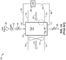
- FIG. 1A illustrates a prior art fuel cell system 10 having a fuel cell stack 12 comprised of a plurality of individual fuel cells 26 connected in series (shown in further detail in FIG. 1B ).
- a stack fan 15 is used to provide process oxidizer (air) and also perform a cooling function by either drawing air 22 through cooling features of the stack 12 and delivering air to the cathode, or by blowing air through the fuel cell stack 12 for cooling and delivering air to the cathode. Additionally, there may be ducting 14 to assist in directing the air flow 22 associated with the fuel cell stack 12.
- a fuel source 32 of hydrogen (or optionally reformate) is provided to stack 12.
- Inlet fuel pressure control can be provided by a pressure regulator 19. The fuel is fed into the fuel cell stack 12 through a fuel inlet valve 16 and exits the fuel cell stack 12 through fuel exit valve or purge valve 28.
- the fuel can be delivered by the pass through method or the periodic purge method.
- the fuel 32 is continuously bled through the fuel cell stack 12 by way of the fuel inlet valve 16 and the fuel exit valve 28 to prevent the accumulation of inert species such as nitrogen and water vapor in the anode chamber.
- the fuel exit valve 28 is held closed while fuel 32 is delivered to the fuel cell stack 12 thought the fuel inlet valve 16.
- inert species such as nitrogen and water vapor accumulate in the anode chamber and impede the electrochemical reaction due to the interference of the mass transport of hydrogen to the anode electrodes. This necessitates the periodic opening of the fuel exit valve 28 to purge the inert species from the anode chamber.
- This procedure leaves fuel within the anode volume, which allows the electrochemical reactions to continue within the fuel cell stack and creates a potential across the fuel cell stack, a potentially unsafe condition. Leaving the purge valve 28 open allows the anode volume to eventually fill with air, thus reducing the potential across the fuel cell stack 12 to zero, inerting the fuel cell stack 12 and eliminating the unsafe condition.
- PEM fuel cell 12 starts and stopping proton exchange membrane (PEM) fuel cell 12 is often detrimental to the platinum catalysts (not shown) used in PEM fuel cells, because high cathode potentials develop during the exchange of oxidizer (air) and hydrogen in the anode volume during the starting and stopping processes. These high cathode potentials cause the corrosion (oxidation) of the carbon catalyst support material on the cathode, leading to the degradation of catalyst itself and a resultant loss of performance.
- the anode volume is placed in a mixed gas condition for an extended period of time, leading to very rapid cathode catalyst degradation.
- US 2003/129462 discloses a procedure for starting up a fuel cell system that is disconnected from its primary load and that has air in both its cathode and anode flow fields; the procedure including: a) connecting an auxiliary resistive load across the cell to reduce the cell voltage; b) initiating a recirculation of the anode flow field exhaust through a recycle loop and providing a limited flow of hydrogen fuel into that recirculating exhaust; c) catalytically reacting the added fuel with oxygen present in the recirculating gases until substantially no oxygen remains within the recycle loop; disconnecting the auxiliary load; and then d) providing normal operating flow rates of fuel and air into respective anode and cathode flow fields and connecting the primary load across the cell.
- the catalytic reaction may take place on the anode or within a catalytic burner disposed within the recycle loop.
- the procedure allows start-up of the fuel cell system without the use of an inert gas purge while minimizing dissolution of the catalyst and corrosion of the catalyst support during the start-up process.
- US2003/134164 discloses a procedure for shutting down an operating fuel cell system; the procedure including: disconnecting the primary electricity using device and stopping the flow of hydrogen containing fuel to the anode, followed by quickly displacing the residual hydrogen with air by blowing air through the anode fuel flow field.
- a sufficiently fast purging of the anode flow field with air eliminates the need for purging with an inert gas such as nitrogen.
- an object of the present invention is a fuel cell system that reduces the residence time of the mixed gas condition at the anode, and reduces the potentials across the fuel cell during the starting and stopping of the fuel cell system, to thereby reduce the impact of mixed gas high cathode potentials.
- the present invention relates to a hydrogen fuel cell electrical power generating system having open cathode proton exchange membrane (PEM) system.
- PEM cathode proton exchange membrane
- accessories are added to control and regulate the fuel cell system such as control systems, safety systems, power conversation and management system and accessories to assist in the start up of the fuel cell stack from a non-operating condition to an operational state.
- the addition of air pumps or compressors are used for the inerting of the fuel cell stack during non-operational periods.
- modified air ducting is used to direct the path of the cooling and process air through the fuel cell stack, and, in some cases, re-circulate the air through the fuel cell stack in order to maintain a proper operating temperature.
- Other embodiments include the use of individual resistors across each fuel cell in the fuel cell stack and/or the inclusion of diodes across each fuel cell in the fuel cell stack.
- the aspect of the invention is a fuel cell system, comprising: a fuel cell stack and a fan configured to provide process air to supply oxidizer to said fuel cell stack; an air duct coupled to said fan and the fuel cell stack; an electrical service load coupled to the fuel cell stack, the electrical service load configured for receiving electrical power generated from reactions within the fuel cell stack; and an auxiliary electrical load coupled to the fuel cell stack; wherein the auxiliary is electrical load configured to reduce potentials across the fuel cell stack; and wherein the air duct is configured to direct the flow of air to the fuel cell stack to provide cooling air to the fuel cell stack; wherein the auxiliary electrical load is located within said air duct to provide cooling air to said auxiliary electrical load.
- the system includes one or more air dampers configured to control the flow of air within the air ducting.
- the system includes a second fan configured to provide cooling air to the auxiliary electrical load.
- the flow of air is re-circulated to force the air heated by fuel cell stack operation to be reintroduced into the fuel cell stack, thereby providing heat for proper operation of the fuel cell stack.
- the system includes resistor elements disposed between cells of the fuel cell stack, wherein the resistor elements are configured to equilibrate potentials across the individual fuel cells.
- Another aspect is a method of operating a fuel cell system having a fuel cell stack, comprising the steps of: from an inert state, engaging an auxiliary electrical load coupled to the fuel cell stack; directing fuel though the fuel cell stack to purge inerting air from the stack; operating a fan to direct air flow across the fuel cell stack; said air flow providing cooling air and process oxidizer to said fuel cell stack; and applying an electrical load across the stack to receive electrical power generated from reactions within the fuel cell stack.
- the inerting air is purged from the fuel cell stack while simultaneously engaging the auxiliary electrical load to lower potentials within the fuel cell stack.
- the method further includes directing cooling air across the auxiliary electrical load.
- the method further includes directing purge air through the fuel cell stack upon stopping of the fuel cell system.
- the method further includes controlling one or more air dampers coupled to the fuel cell stack to direct the airflow to the fuel cell stack and auxiliary electrical load; and operating the one or more air dampers to redirect air heated by the fuel cell stack back into the fuel cell stack, thereby providing heat for operation of the fuel cell stack.
- the method further includes controlling the opening and closing of the one or more air dampers to allow or limit infusion of ambient air into the air duct.
- FIG. 2A shows a PEM fuel cell system 40 configured to provide increased functionality and robustness in accordance with the present invention.
- purge air pump or compressor 52 to quickly move purge air 56 through the fuel cell stack 42 by way of the air purge inlet valve 54 upon stopping of the fuel cell system.
- An auxiliary or external electrical load 48 is used to reduce the potentials across the fuel cell stack 42 and consequently across the individual fuel cells 26 during the starting and stopping of the fuel cell system 40.
- Attendant with the auxiliary electrical load 48 is an external or auxiliary electrical load cooling fan 46 that is configured to force air 50 across or through the auxiliary electrical load 48 for cooling the auxiliary electrical load 48 during its operation.
- the auxiliary electrical load cooling fan 46 may draw air 50 the opposite direction (not shown) through the auxiliary electrical load 48.
- the auxiliary electrical load 48 and auxiliary electrical load cooling fan 46 are actuated by the closing of switch or relay 44, which causes the auxiliary electrical load 48 to be in electrical parallel with the fuel cell stack 42.
- fuel cell stack 42 may optionally include resistor elements 58 and or diodes 60 coupled to the individual fuel cells 26.
- the resistor elements 58 aid in equilibrating the potentials across the individual fuel cells 26, while the diodes 60 prevent the individual fuel cells 26 from reversing polarity.
- the fuel cell system 40 is started by first engaging the auxiliary electrical load 48 and the auxiliary electrical load cooling fan 46 by the closing of switch or relay 44.
- the exit purge valve 28 is opened to vent the fuel cell stack 42, followed by the opening of the inlet valve 16 to then allow the fuel to be purged though the fuel cell stack 42.
- the simultaneous purging of the inerting air 56 from the fuel cell stack 42 and the engagement of the auxiliary electrical load 48 lowers the potentials within the fuel cell stack 42, reducing cathode catalyst corrosion during the period when there is a mixed gas condition within the fuel cell stack 42.
- the fuel 32 is purged through the fuel cell stack 42 for a sufficient amount of time to assure the complete displacement of the inerting air from the fuel cell stack 42.
- the exit purge valve 28 is closed, the switch or relay 44 is opened, the stack fan 15 is engaged, and the main electrical load 20 is applied by the closing of relay or switch 24.
- the resistor elements 58 of FIG. 2B aid in providing more consistent potentials among the individual cells 26 within the fuel cell stack 42.
- the diodes 60 prevent the occurrence of reverse potentials among the individual cells 26 within the fuel cell stack 42.
- the fuel cell stack 42 (as well as fuel cell stack 102 shown in FIGS. 3A-C and 4A-C described below) and individual fuel cells 26 preferably comprise open-cathode proton exchange membrane (PEM) commonly available in the art.
- PEM open-cathode proton exchange membrane
- fuel e.g. hydrogen or reformate
- fuel source 32 is regulated to the proper operational pressure by pressure regulator 19 and is passed into the fuel cell stack 42 by way of fuel inlet valve 16.
- Fuel is removed from the stack through the exit or purge valve 28 using the periodic purge method or pass through method.
- air 22 is supplied to the open cathode by means of a stack fan 15 by drawing air through the fuel cell stack as shown in FIG. 2A , or optionally by blowing air 22 through the fuel cell stack, (e.g. air flow in opposite direction not shown).
- the stack fan 15 also serves to cool the fuel cell stack 42 during operation.
- the electrical power generated by the reactions within the fuel cell stack are delivered to the electrical load 20 through electrical leads (cathode lead 18 and anode lead 30), and preferably through switch or relay 24.
- the fuel cell system 40 ceases operation by disconnection of the electrical load 20 via opening the switch or relay 24, opening the purge valve 28 to purge the anode volume of water and other matter and providing a volume of fresh fuel 32 into the anode volume, continuing to run the stack fan 15 to cool the fuel cell stack 42, shutting off the stack fan 15 after the fuel cell stack has cooled satisfactorily, and engaging the auxiliary electrical load 48 and the auxiliary electrical load cooling fan 46 by the closing of switch or relay 44.
- the fuel inlet valve 16 is then closed, and the air purge inlet valve 54 is opened to force purge air 56 through the fuel cell stack 42 by means of the air purge pump 52 through the air purge inlet valve 54.
- Purge air 56 is forced through the fuel cell stack 42 for a sufficient period of time to allow the fuel remaining within the anode volume to be purged.
- the residence time of mixed gases is reduced and damage to cathode catalyst is reduced, as well as performance losses resulting from the degraded cathode catalyst.
- the simultaneous purging of the fuel from the fuel cell stack 42 and the engagement of the auxiliary electrical load 48 lowers the potentials within the fuel cell stack 42, reducing cathode catalyst corrosion during the periods when there is a mixed gas condition within the fuel cell stack 42.
- the resistor elements 58 aid in providing more consistent potentials among the individual cells 26 within the fuel cell stack 42 while the diodes 60, if used, prevent the occurrence of reverse potentials among the individual cells 26 within the fuel cell stack 42.
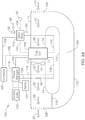
- FIGS. 3A , 3B and 3C show a fuel cell system 100 with consolidated features configured to improve the operation and extend the operational range of the fuel cell.
- System 100 includes a fuel cell stack 102 and cell stack fan 15, with augmented ducting 14 to allow for a recirculation return passage 104 by means of recirculation return ducting 112.
- the return ducting 112 may be a structural part the fuel cell system 100 or it may be realized by the placement of the fuel cell system 100 with in a cabinet or other enclosure (not shown), whereby the various walls, panels, divider or other structures of the cabinet or enclosure function as ducting for the fuel cell engine 100.
- the auxiliary electrical load 48 is placed within the ducting in such a location that the stack fan 15 provides cooling air 22 to auxiliary electrical load 48 as well as cooling air and process air to the fuel cell stack 102.
- the stack fan 15 draws air 22 through the fuel cell stack 102 and then blows the same air over or through the auxiliary electrical load 48 to providing cooling.
- the stack fan 15 may blow air 22 through the fuel cell stack 102 and draw air 22 over or through the auxiliary electrical load 48 (e.g. reverse to the flow of the air in FIG. 3A ).
- the placement of the fuel cell stack 102, stack fan 15 and the auxiliary electrical load 48 may be configured in different arrangements in which the air 22 is drawn or blown through the fuel cell stack 102 and the same air 22 is drawn or blown over or through the auxiliary electrical load 48 by means of different locations within the ducting 14, 112.
- the stack fan 15 may be positioned downstream from the auxiliary electrical load 48 or upstream from the fuel cell 102.
- System 100 may also comprise with a single integrated valve body 114 that incorporates the valve function of all or many of the individual valves of system 40. That is, rather than have separate valves and valve bodies such as the fuel inlet valve 16, the purge valve 28, the pressure regulation valve 19 and the purge air inlet valve 54 as separate components, the valve body 114 stands as a single component serving the various functions. While a single component valve body 114 may incorporate the assorted valve functions, all valve functions may not be built-in to the valve body 114. As an example, the purge valve 28 and or the pressure regulator 19 may remain as separate component for practical design reasons and not be incorporated into the valve body. Furthermore, any valve configurations shown in FIGS. 2A , 3A through 3C and 4A through 4C may be used interchangeably.
- Power is delivered from the fuel cell stack 102 though the stack power lead 120 to the fuel cell system power manger 116, and returned to the fuel cell stack 102 through the stack return power lead 118. Because the stack potential can vary significantly as the power drawn from the fuel cell stack 102 varies, and may not be suitable for the main service load 122, the power coming from the fuel cell stack 102 is preferably conditioned or managed in the power manager 116 to provide a constant potential to the main service load 122.
- a computer based fuel cell system controller 126 is provided to monitor the condition of the fuel cell stack, operate the valves of the valve body 114, as well as any other separate valves, and monitor and control the power manger 116.
- System 100 may also include a transient energy storage 124 capability in the form of batteries or supercapacitors.
- the fuel cell system 100 may serve as a back-up power generator that only operates when there is a grid power outage.
- the transient energy storage 124 can provide electrical power for the period of time required for the fuel cell system 100 to come to its operational state.
- Air flow 22 within the ducting is controlled by the use of vaned louvers or dampers 106, 108, 110 which are in turn regulated by the fuel cell system controller 126.
- the vaned louvers or dampers 106, 108, 110 may be comprised of single vanes (not shown) or multiple vanes as shown in FIGS. 3A through 3C .
- the air inlet damper 106 of system 100 is fully open and allows external air 21 to enter the fuel cell system 100 by means of being drawn in by the stack fan 15, the air 22 is then drawn through the fuel cell stack 102, cooling the fuel cell stack 102, and providing process air (oxygen) to the fuel cell stack 102.
- the air 22 is caused to exit the fuel cell system through the open air exit damper 108 and out to the external environment 23.
- the air 22 is caused to pass over or through the external/auxiliary electrical load 48 to facilitate cooling of the auxiliary electrical load 48.
- the recirculation air damper 110 is fully closed to ensure that the heated air 22 exiting the fuel cell stack 102 is not drawn back through the stack 102.
- the operational mode of FIG. 3A is used to effect maximum cooling of the fuel cell stack 102 during operation at higher environmental temperatures, and to reject to the outside environment 23 as much of the heat generated by the fuel cell stack 102 as possible.
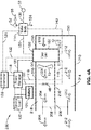
- FIG. 3B shows a second operational mode wherein the inlet air damper 106 and the exit air damper 108 are closed while the recirculation air damper 110 is fully open.
- the air 22 heated by the fuel cell stack 15 is caused to be recalculated back through the recirculation damper 110 and the recirculation return passage 104 by means of recirculation return ducting 112.
- the recirculated air 25 is reintroduced into the fuel cell stack 102 in order to heat the fuel cell stack 102 to promote higher performance operation at low environmental temperatures and or to bring the fuel cell stack 102 quickly up to the desired operating temperature.
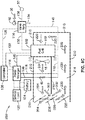
- FIG. 3C A third operational mode is shown in FIG. 3C .
- the inlet air damper 106, the outlet air damper 108, and the recirculation damper 110 are partially open allowing a portion of the air 22 to pass out of the fuel cell system 100 (external air flow 23) via the exit air damper 108, while allowing another portion of air 25 to be re-circulated by way the recirculation damper 110 and the recirculation return passage 104 by means of recirculation return ducting 112.
- the re-circulated air 25 is mixed with the air 21 entering through the inlet air damper 106 and reintroduced into the fuel cell stack 102 in order to heat the fuel cell stack 102 to a predetermined operating temperature.
- the operational mode of FIG. 3C is applied when the air 21 passing through the inlet air damper 106 is below the predetermined operating temperature of the fuel cell stack 102 and is to be warmed to maintain the fuel cell stack at the predetermined operating temperature.
- This operational mode is generally the nominal operating mode.
- fuel from a fuel source 32 is delivered through the fuel inlet line 136 to the valve body 114 and regulated to the predetermined operating pressure.
- the fuel may be delivered to an external fuel pressure regulator (not shown) and then to the valve body 114.
- the fuel cell system controller 126 provides a command signal to cause the fuel inlet valve incorporated within the valve body 114 to be in the open state allowing fuel to flow into the fuel cell stack 102 through the stack fuel inlet line 130.
- a purge valve within the valve body 114 or an external purge valve (not shown) is commanded to open by the fuel cell system controller 126, allowing fuel to pass through the fuel cell stack 102 and the stack purge line 140 and out the purge port 134.
- the fuel cell system controller 126 monitors the fuel cell stack 102 and the fuel cell system 100 through the stack and system monitor leads 132 (which may be coupled to temperature sensors, voltage taps, pressure sensors, etc., not shown). Parameters monitored by the fuel cell system controller 126 may include but are not limited to: fuel cell stack 102 temperature, individual fuel cell 26 potentials, inlet 21/outlet 23 air temperature, re-circulated air 25 temperature, humidity, and or pressure differential across the fuel cell stack 102, etc.
- the fuel cell system controller 126 determines and controls the state of valves within (or external to) the valve body 114, as well as the speed of the stack fan 15, positions of the inlet air damper 106, the exit air damper 108, and the recirculation air damper 110 in order to maintain the predetermined fuel cell stack 102 temperature.
- the air dampers 106, 108, and 100 preferably include, or are configured to operate with, actuation means (e.g. servo motor or other actuation device available in the art, not shown) to drive the position of the air dampers (e.g. open, closed, or partially closed) according to a set program, and/or via feedback from the monitored parameters).
- actuation means e.g. servo motor or other actuation device available in the art, not shown
- the fuel cell system controller 126 controls the output potential of the power manager 116 and monitors the current drawn by the main electrical or service load 122. Fuel cell system controller 126 also prevents overload conditions, and commands the power manager 116 (or alternatively an external switch or relay (not shown)) to cause the fuel cell stack power to be delivered to the auxiliary electrical load 48 through the auxiliary electrical load leads 138 and manages the charging of the transition energy storage device 124.
- FIGS. 4A , 4B and 4C illustrate an alternative system 200 comprising a single damper 206 which may be single or multi-vaned, and accompanying ducting 210.
- System 100 comprises a single folded duct 210 instead of the inlet damper 106, the outlet damper 108 and the recirculation damper 110 of system 100 ( FIGS 3A , 3B , and 3C ).
- the ducting 210 of system 200 has combination incoming/recirculating air section 214 and a return/outlet air section 208 separated by a duct divider 216.
- the ducting 210 and 216 may be a structural part the fuel cell system 200, or it may be realized by the placement of the fuel cell system 200 with in a cabinet or other enclosure (not shown) wherein the walls, panels, divider or other structures of the cabinet or enclosure function as ducting for the fuel cell engine 200.
- the stack fan 15 draws air through the fuel cell stack 102 and then blows the same air over or through the external/auxiliary electrical load 48 to provide cooling as shown in FIGS 4A-4C .
- the stack fan 15 may blow air through the fuel cell stack 102 and draw air over or through the auxiliary electrical load 48 in the reverse flow of the air as shown in the FIGS. 4A-4C .
- the placement of the fuel cell stack 102, stack fan 15 and the auxiliary electrical load 48 may be located in different positions within the ducting 210 such that air is drawn or blown through the fuel cell stack 102, or alternatively drawn or blown over or through the auxiliary electrical load 48 by means of different locations within the ducting 210.
- FIG. 4A illustrates a first operational mode of system 200, wherein the single air damper 206 is fully open and allows external air 212 to enter the fuel cell system 200 by means of being drawn into the inlet section 214 by the stack fan 15.
- the air 212 is then drawn through the fuel cell stack 102, thereby cooling the fuel cell stack 102, and providing process air (oxygen) to the fuel cell stack 102.
- the heated air 204 is caused to exit the fuel cell system through the open air damper 206 by way of the outlet section 218 and into the external environment.
- the air 204, 212 is caused to pass over or through the auxiliary electrical load 48 to facilitate cooling of the auxiliary electrical load 48.
- the operational mode of FIG. 4A is preferably used to affect maximum cooling of the fuel cell stack 102 during operation at higher environmental temperatures, and to reject to the outside environment as much of the heat generated by the fuel cell stack 102 as possible. It is also appreciated that the air flows 212, 204 may be reversed to cause the air to be blown through the fuel cell stack 102 (e.g. duct 218 becomes the air intake).
- FIG. 4B illustrates a second operational mode of system 200, wherein the single air damper 206 is fully closed.
- the air 204 heated by the fuel cell stack 15 is caused to be re-circulate back through the recirculation return passage 208 and re-circulating air section 214 and back into the fuel cell stack 102.
- the re-circulating air 202 is reintroduced into the fuel cell stack 102 in order to heat the fuel cell stack 102 to promote higher performance operation at low temperatures and/or to bring the fuel cell stack 102 quickly up to the desired operating temperature.
- the air 204 is caused to pass over or through the auxiliary external electrical load 48 to facilitate cooling of the auxiliary electrical load 48. It is also appreciated that the air flows 202, 204 may also be reversed, causing the air to be blown through the fuel cell stack 102.
- FIG. 4C illustrates a third operational mode of system 200, wherein the air damper 206 is partially open allowing a portion of the heated air 204 to pass to pass through and out of the fuel cell system 200 through the air damper 206 while allowing another portion of the air 202 to be re-circulated though the recirculation return passage 208.
- the re-circulated air 202 is mixed with the air 222 entering through the air damper 206 to form return air mixture 220, and is reintroduced into the fuel cell stack 102 in order to heat the fuel cell stack 102 to a predetermined operating temperature.
- This operational variation is applied when the air 222 passing through the air damper 206 is cooler than needed to maintain the predetermined operating temperature of the fuel cell stack 102 and is to be warmed to maintain the fuel cell stack at the predetermined operating temperature.
- the operational mode of FIG. 4C is typically the nominal operating mode. It is also appreciated that the air flows 202, 204, 220, and 222 may be reversed, causing the air to be blown through the fuel cell stack 102.
- fuel from a fuel source 32 is delivered through the fuel inlet line 136 to the valve body 114 and regulated to the predetermined operating pressure or delivered to an external fuel pressure regulator (not shown) and then to the valve body 114.
- the fuel cell system controller 126 provides a command signal to cause the fuel inlet valve incorporated within the valve body 114 to be in the open state allowing fuel to flow into the fuel cell stack through the stack fuel inlet line 130.
- a purge valve within the valve body 114 or an external purge valve (not shown) is commanded to open by the fuel cell system controller 126 allowing fuel to pass through the fuel cell stack 102 and the stack purge line 140 and out the purge port 134.
- the fuel cell system controller 126 monitors the fuel cell stack 102 and the fuel cell system 200 through the stack and system monitor leads 132.
Landscapes
- Engineering & Computer Science (AREA)
- Chemical & Material Sciences (AREA)
- Life Sciences & Earth Sciences (AREA)
- Sustainable Development (AREA)
- Manufacturing & Machinery (AREA)
- Sustainable Energy (AREA)
- Chemical Kinetics & Catalysis (AREA)
- Electrochemistry (AREA)
- General Chemical & Material Sciences (AREA)
- Combustion & Propulsion (AREA)
- Fuel Cell (AREA)
Description
- This application claims priority to
U.S. patent application serial number 13/196,837 filed on August 2, 2011 U.S. provisional patent application serial number 61/444,595 filed on February 18, 2011 - This invention pertains generally to a hydrogen fuel cell electrical power generating system, and more particularly to an open cathode proton exchange membrane (PEM) system.
-
FIG. 1A illustrates a prior artfuel cell system 10 having afuel cell stack 12 comprised of a plurality ofindividual fuel cells 26 connected in series (shown in further detail inFIG. 1B ). Astack fan 15 is used to provide process oxidizer (air) and also perform a cooling function by either drawingair 22 through cooling features of thestack 12 and delivering air to the cathode, or by blowing air through thefuel cell stack 12 for cooling and delivering air to the cathode. Additionally, there may be ducting 14 to assist in directing theair flow 22 associated with thefuel cell stack 12. In these systems, afuel source 32 of hydrogen (or optionally reformate) is provided to stack 12. Inlet fuel pressure control can be provided by apressure regulator 19. The fuel is fed into thefuel cell stack 12 through afuel inlet valve 16 and exits thefuel cell stack 12 through fuel exit valve orpurge valve 28. - The fuel can be delivered by the pass through method or the periodic purge method. In the pass through method, the
fuel 32 is continuously bled through thefuel cell stack 12 by way of thefuel inlet valve 16 and thefuel exit valve 28 to prevent the accumulation of inert species such as nitrogen and water vapor in the anode chamber. - In the periodic purge method, the
fuel exit valve 28 is held closed whilefuel 32 is delivered to thefuel cell stack 12 thought thefuel inlet valve 16. Over time, inert species such as nitrogen and water vapor accumulate in the anode chamber and impede the electrochemical reaction due to the interference of the mass transport of hydrogen to the anode electrodes. This necessitates the periodic opening of thefuel exit valve 28 to purge the inert species from the anode chamber. - Electrical power is taken from the
fuel cell stack 12 throughelectrical leads switch 24 to anelectrical service load 20. Shutting down the system may simply entail disconnecting theelectrical service load 20 by opening the switch orrelay 24, or discontinuing the supply of fuel to the fuel cell stack by closing thefuel supply valve 16 and opening thepurge valve 28 to allow the pressure within the anode volume to equilibrate and then turning off thestack fan 15, stopping the flow ofair 22. - This procedure leaves fuel within the anode volume, which allows the electrochemical reactions to continue within the fuel cell stack and creates a potential across the fuel cell stack, a potentially unsafe condition. Leaving the
purge valve 28 open allows the anode volume to eventually fill with air, thus reducing the potential across thefuel cell stack 12 to zero, inerting thefuel cell stack 12 and eliminating the unsafe condition. - However, starting and stopping proton exchange membrane (PEM)
fuel cell 12 is often detrimental to the platinum catalysts (not shown) used in PEM fuel cells, because high cathode potentials develop during the exchange of oxidizer (air) and hydrogen in the anode volume during the starting and stopping processes. These high cathode potentials cause the corrosion (oxidation) of the carbon catalyst support material on the cathode, leading to the degradation of catalyst itself and a resultant loss of performance. - In addition, when simply opening the purge valve and allowing air to be drawn into and through the fuel cell stack, the anode volume is placed in a mixed gas condition for an extended period of time, leading to very rapid cathode catalyst degradation.
-
US 2003/129462 discloses a procedure for starting up a fuel cell system that is disconnected from its primary load and that has air in both its cathode and anode flow fields; the procedure including: a) connecting an auxiliary resistive load across the cell to reduce the cell voltage; b) initiating a recirculation of the anode flow field exhaust through a recycle loop and providing a limited flow of hydrogen fuel into that recirculating exhaust; c) catalytically reacting the added fuel with oxygen present in the recirculating gases until substantially no oxygen remains within the recycle loop; disconnecting the auxiliary load; and then d) providing normal operating flow rates of fuel and air into respective anode and cathode flow fields and connecting the primary load across the cell. The catalytic reaction may take place on the anode or within a catalytic burner disposed within the recycle loop. The procedure allows start-up of the fuel cell system without the use of an inert gas purge while minimizing dissolution of the catalyst and corrosion of the catalyst support during the start-up process. -
US2003/134164 discloses a procedure for shutting down an operating fuel cell system; the procedure including: disconnecting the primary electricity using device and stopping the flow of hydrogen containing fuel to the anode, followed by quickly displacing the residual hydrogen with air by blowing air through the anode fuel flow field. A sufficiently fast purging of the anode flow field with air eliminates the need for purging with an inert gas such as nitrogen. - Accordingly, an object of the present invention is a fuel cell system that reduces the residence time of the mixed gas condition at the anode, and reduces the potentials across the fuel cell during the starting and stopping of the fuel cell system, to thereby reduce the impact of mixed gas high cathode potentials. At least some of these objectives will be met in the description provided below.
- The present invention relates to a hydrogen fuel cell electrical power generating system having open cathode proton exchange membrane (PEM) system. The present invention simplifies operation and fabrication of the fuel cell system.
- In some embodiments, accessories are added to control and regulate the fuel cell system such as control systems, safety systems, power conversation and management system and accessories to assist in the start up of the fuel cell stack from a non-operating condition to an operational state.
- Also, to assist in the shut down from the operational state to a non-operating condition such as the addition of auxiliary electrical loads, the addition of air pumps or compressors are used for the inerting of the fuel cell stack during non-operational periods.
- In addition, in some embodiments, modified air ducting is used to direct the path of the cooling and process air through the fuel cell stack, and, in some cases, re-circulate the air through the fuel cell stack in order to maintain a proper operating temperature.
- Other embodiments include the use of individual resistors across each fuel cell in the fuel cell stack and/or the inclusion of diodes across each fuel cell in the fuel cell stack.
- Further embodiments consolidate the aforementioned accessories in a simplification of the fuel cell power system for cost reduction and ease of operation.
- The aspect of the invention is a fuel cell system, comprising: a fuel cell stack and a fan configured to provide process air to supply oxidizer to said fuel cell stack; an air duct coupled to said fan and the fuel cell stack; an electrical service load coupled to the fuel cell stack, the electrical service load configured for receiving electrical power generated from reactions within the fuel cell stack; and an auxiliary electrical load coupled to the fuel cell stack; wherein the auxiliary is electrical load configured to reduce potentials across the fuel cell stack; and wherein the air duct is configured to direct the flow of air to the fuel cell stack to provide cooling air to the fuel cell stack; wherein the auxiliary electrical load is located within said air duct to provide cooling air to said auxiliary electrical load.
- In one embodiment, the system includes one or more air dampers configured to control the flow of air within the air ducting.
- In another embodiment, the system includes a second fan configured to provide cooling air to the auxiliary electrical load.
- In one embodiment, the flow of air is re-circulated to force the air heated by fuel cell stack operation to be reintroduced into the fuel cell stack, thereby providing heat for proper operation of the fuel cell stack.
- In a further embodiment, the system includes resistor elements disposed between cells of the fuel cell stack, wherein the resistor elements are configured to equilibrate potentials across the individual fuel cells.
- Another aspect is a method of operating a fuel cell system having a fuel cell stack, comprising the steps of: from an inert state, engaging an auxiliary electrical load coupled to the fuel cell stack; directing fuel though the fuel cell stack to purge inerting air from the stack; operating a fan to direct air flow across the fuel cell stack; said air flow providing cooling air and process oxidizer to said fuel cell stack; and applying an electrical load across the stack to receive electrical power generated from reactions within the fuel cell stack.
- In one embodiment of the current aspect, the inerting air is purged from the fuel cell stack while simultaneously engaging the auxiliary electrical load to lower potentials within the fuel cell stack.
- In another embodiment the method further includes directing cooling air across the auxiliary electrical load.
- In another embodiment the method further includes directing purge air through the fuel cell stack upon stopping of the fuel cell system.
- In a further embodiment the method further includes controlling one or more air dampers coupled to the fuel cell stack to direct the airflow to the fuel cell stack and auxiliary electrical load; and operating the one or more air dampers to redirect air heated by the fuel cell stack back into the fuel cell stack, thereby providing heat for operation of the fuel cell stack.
- In yet a further embodiment the method further includes controlling the opening and closing of the one or more air dampers to allow or limit infusion of ambient air into the air duct.
- Further aspects of the invention will be brought out in the following portions of the specification, wherein the detailed description is for the purpose of fully disclosing preferred embodiments of the invention without placing limitations thereon.
- The invention will be more fully understood by reference to the following drawings which are for illustrative purposes only:
-
FIG. 1A is a schematic depiction of a prior art open cathode fuel cell system. -
FIG. 1B is a schematic depiction of a detail of the fuel cell stack ofFIG. 1A showing the arrangement of individual fuel cells. -
FIG. 2A is a schematic depiction of a first fuel cell system of the present invention. -
FIG. 2B is a schematic diagram of a detail of the fuel cell stack ofFIG. 2A showing the arrangement of individual fuel cells parallel resister elements and diodes. -
FIGS. 3A ,3B , and3C are schematic diagrams of a second embodiment of the invention showing three operational variations.FIG. 3A shows a pass through mode,FIG. 3B shows a full recirculation mode, andFIG. 3C shows a partial recirculation mode. -
FIGS. 4A ,4B , and4C are schematic diagrams of a third embodiment of the invention showing three operational variations:FIG. 4A shows a pass through mode,FIG. 4B shows a full recirculation mode, andFIG. 3C shows a partial recirculation mode. - The following is a discussion of the embodiments of the invention on the improvements of an open cathode fuel cell system making use of auxiliary accessories, simplifications and improvements in methods of construction to achieve the improvements.
-
FIG. 2A shows a PEMfuel cell system 40 configured to provide increased functionality and robustness in accordance with the present invention. To reduce the impact of mixed gas high cathode potentials, it is advantageous to reduce the residence time of the mixed gas condition at the anode. This is accomplished insystem 40 by implementation of purge air pump orcompressor 52 to quickly movepurge air 56 through thefuel cell stack 42 by way of the airpurge inlet valve 54 upon stopping of the fuel cell system. - An auxiliary or external
electrical load 48 is used to reduce the potentials across thefuel cell stack 42 and consequently across theindividual fuel cells 26 during the starting and stopping of thefuel cell system 40. Attendant with the auxiliaryelectrical load 48 is an external or auxiliary electricalload cooling fan 46 that is configured to forceair 50 across or through the auxiliaryelectrical load 48 for cooling the auxiliaryelectrical load 48 during its operation. Optionally, the auxiliary electricalload cooling fan 46 may drawair 50 the opposite direction (not shown) through the auxiliaryelectrical load 48. The auxiliaryelectrical load 48 and auxiliary electricalload cooling fan 46 are actuated by the closing of switch orrelay 44, which causes the auxiliaryelectrical load 48 to be in electrical parallel with thefuel cell stack 42. - As shown in
FIG. 2B ,fuel cell stack 42 may optionally includeresistor elements 58 and ordiodes 60 coupled to theindividual fuel cells 26. Theresistor elements 58 aid in equilibrating the potentials across theindividual fuel cells 26, while thediodes 60 prevent theindividual fuel cells 26 from reversing polarity. - From the inert state, i.e., ambient temperature and air residing on both the anode and cathode and no fuel within the system, the
fuel cell system 40 is started by first engaging the auxiliaryelectrical load 48 and the auxiliary electricalload cooling fan 46 by the closing of switch orrelay 44. Theexit purge valve 28 is opened to vent thefuel cell stack 42, followed by the opening of theinlet valve 16 to then allow the fuel to be purged though thefuel cell stack 42. The simultaneous purging of theinerting air 56 from thefuel cell stack 42 and the engagement of the auxiliaryelectrical load 48 lowers the potentials within thefuel cell stack 42, reducing cathode catalyst corrosion during the period when there is a mixed gas condition within thefuel cell stack 42. Thefuel 32 is purged through thefuel cell stack 42 for a sufficient amount of time to assure the complete displacement of the inerting air from thefuel cell stack 42. After this, theexit purge valve 28 is closed, the switch orrelay 44 is opened, thestack fan 15 is engaged, and the mainelectrical load 20 is applied by the closing of relay orswitch 24. - During the purging of the inerting air from the
stack 42, theresistor elements 58 ofFIG. 2B , if used, aid in providing more consistent potentials among theindividual cells 26 within thefuel cell stack 42. Furthermore, thediodes 60, if used, prevent the occurrence of reverse potentials among theindividual cells 26 within thefuel cell stack 42. - In a preferred embodiment, the fuel cell stack 42 (as well as
fuel cell stack 102 shown inFIGS. 3A-C and4A-C described below) andindividual fuel cells 26 preferably comprise open-cathode proton exchange membrane (PEM) commonly available in the art. - During normal operation, fuel (e.g. hydrogen or reformate) delivered from a
fuel source 32 is regulated to the proper operational pressure bypressure regulator 19 and is passed into thefuel cell stack 42 by way offuel inlet valve 16. Fuel is removed from the stack through the exit or purgevalve 28 using the periodic purge method or pass through method. Concurrently,air 22 is supplied to the open cathode by means of astack fan 15 by drawing air through the fuel cell stack as shown inFIG. 2A , or optionally by blowingair 22 through the fuel cell stack, (e.g. air flow in opposite direction not shown). Thestack fan 15 also serves to cool thefuel cell stack 42 during operation. The electrical power generated by the reactions within the fuel cell stack are delivered to theelectrical load 20 through electrical leads (cathode lead 18 and anode lead 30), and preferably through switch orrelay 24. - The
fuel cell system 40 ceases operation by disconnection of theelectrical load 20 via opening the switch orrelay 24, opening thepurge valve 28 to purge the anode volume of water and other matter and providing a volume offresh fuel 32 into the anode volume, continuing to run thestack fan 15 to cool thefuel cell stack 42, shutting off thestack fan 15 after the fuel cell stack has cooled satisfactorily, and engaging the auxiliaryelectrical load 48 and the auxiliary electricalload cooling fan 46 by the closing of switch orrelay 44. - The
fuel inlet valve 16 is then closed, and the airpurge inlet valve 54 is opened to forcepurge air 56 through thefuel cell stack 42 by means of theair purge pump 52 through the airpurge inlet valve 54.Purge air 56 is forced through thefuel cell stack 42 for a sufficient period of time to allow the fuel remaining within the anode volume to be purged. - By forcing the
purge air 56 through the anode volume, the residence time of mixed gases is reduced and damage to cathode catalyst is reduced, as well as performance losses resulting from the degraded cathode catalyst. - In addition, the simultaneous purging of the fuel from the
fuel cell stack 42 and the engagement of the auxiliaryelectrical load 48 lowers the potentials within thefuel cell stack 42, reducing cathode catalyst corrosion during the periods when there is a mixed gas condition within thefuel cell stack 42. During the purging of the fuel from thestack 42, theresistor elements 58, if used, aid in providing more consistent potentials among theindividual cells 26 within thefuel cell stack 42 while thediodes 60, if used, prevent the occurrence of reverse potentials among theindividual cells 26 within thefuel cell stack 42. -
FIGS. 3A ,3B and3C show afuel cell system 100 with consolidated features configured to improve the operation and extend the operational range of the fuel cell.System 100 includes afuel cell stack 102 andcell stack fan 15, withaugmented ducting 14 to allow for arecirculation return passage 104 by means ofrecirculation return ducting 112. Thereturn ducting 112 may be a structural part thefuel cell system 100 or it may be realized by the placement of thefuel cell system 100 with in a cabinet or other enclosure (not shown), whereby the various walls, panels, divider or other structures of the cabinet or enclosure function as ducting for thefuel cell engine 100. The auxiliaryelectrical load 48 is placed within the ducting in such a location that thestack fan 15 providescooling air 22 to auxiliaryelectrical load 48 as well as cooling air and process air to thefuel cell stack 102. - In a preferred embodiment of
system 100, thestack fan 15 drawsair 22 through thefuel cell stack 102 and then blows the same air over or through the auxiliaryelectrical load 48 to providing cooling. In an alternative embodiment (not shown), thestack fan 15 may blowair 22 through thefuel cell stack 102 and drawair 22 over or through the auxiliary electrical load 48 (e.g. reverse to the flow of the air inFIG. 3A ). - In further alternative embodiments (not shown), the placement of the
fuel cell stack 102, stackfan 15 and the auxiliaryelectrical load 48 may be configured in different arrangements in which theair 22 is drawn or blown through thefuel cell stack 102 and thesame air 22 is drawn or blown over or through the auxiliaryelectrical load 48 by means of different locations within theducting stack fan 15 may be positioned downstream from the auxiliaryelectrical load 48 or upstream from thefuel cell 102. -
System 100 may also comprise with a singleintegrated valve body 114 that incorporates the valve function of all or many of the individual valves ofsystem 40. That is, rather than have separate valves and valve bodies such as thefuel inlet valve 16, thepurge valve 28, thepressure regulation valve 19 and the purgeair inlet valve 54 as separate components, thevalve body 114 stands as a single component serving the various functions. While a singlecomponent valve body 114 may incorporate the assorted valve functions, all valve functions may not be built-in to thevalve body 114. As an example, thepurge valve 28 and or thepressure regulator 19 may remain as separate component for practical design reasons and not be incorporated into the valve body. Furthermore, any valve configurations shown inFIGS. 2A ,3A through 3C and 4A through 4C may be used interchangeably. - Power is delivered from the
fuel cell stack 102 though thestack power lead 120 to the fuel cellsystem power manger 116, and returned to thefuel cell stack 102 through the stackreturn power lead 118. Because the stack potential can vary significantly as the power drawn from thefuel cell stack 102 varies, and may not be suitable for themain service load 122, the power coming from thefuel cell stack 102 is preferably conditioned or managed in thepower manager 116 to provide a constant potential to themain service load 122. - A computer based fuel
cell system controller 126 is provided to monitor the condition of the fuel cell stack, operate the valves of thevalve body 114, as well as any other separate valves, and monitor and control thepower manger 116. -
System 100 may also include atransient energy storage 124 capability in the form of batteries or supercapacitors. In one embodiment, thefuel cell system 100 may serve as a back-up power generator that only operates when there is a grid power outage. Thus, thetransient energy storage 124 can provide electrical power for the period of time required for thefuel cell system 100 to come to its operational state. -
Air flow 22 within the ducting is controlled by the use of vaned louvers ordampers cell system controller 126. The vaned louvers ordampers FIGS. 3A through 3C . - In a first operational mode shown in
FIG. 3A , theair inlet damper 106 ofsystem 100 is fully open and allowsexternal air 21 to enter thefuel cell system 100 by means of being drawn in by thestack fan 15, theair 22 is then drawn through thefuel cell stack 102, cooling thefuel cell stack 102, and providing process air (oxygen) to thefuel cell stack 102. Theair 22 is caused to exit the fuel cell system through the openair exit damper 108 and out to theexternal environment 23. As needed, theair 22 is caused to pass over or through the external/auxiliaryelectrical load 48 to facilitate cooling of the auxiliaryelectrical load 48. During this operational mode, therecirculation air damper 110 is fully closed to ensure that theheated air 22 exiting thefuel cell stack 102 is not drawn back through thestack 102. - The operational mode of
FIG. 3A is used to effect maximum cooling of thefuel cell stack 102 during operation at higher environmental temperatures, and to reject to theoutside environment 23 as much of the heat generated by thefuel cell stack 102 as possible. -
FIG. 3B shows a second operational mode wherein theinlet air damper 106 and theexit air damper 108 are closed while therecirculation air damper 110 is fully open. In this operational mode, theair 22 heated by thefuel cell stack 15 is caused to be recalculated back through therecirculation damper 110 and therecirculation return passage 104 by means ofrecirculation return ducting 112. The recirculatedair 25 is reintroduced into thefuel cell stack 102 in order to heat thefuel cell stack 102 to promote higher performance operation at low environmental temperatures and or to bring thefuel cell stack 102 quickly up to the desired operating temperature. - A third operational mode is shown in
FIG. 3C . In this mode, theinlet air damper 106, theoutlet air damper 108, and therecirculation damper 110 are partially open allowing a portion of theair 22 to pass out of the fuel cell system 100 (external air flow 23) via theexit air damper 108, while allowing another portion ofair 25 to be re-circulated by way therecirculation damper 110 and therecirculation return passage 104 by means ofrecirculation return ducting 112. There-circulated air 25 is mixed with theair 21 entering through theinlet air damper 106 and reintroduced into thefuel cell stack 102 in order to heat thefuel cell stack 102 to a predetermined operating temperature. - The operational mode of
FIG. 3C is applied when theair 21 passing through theinlet air damper 106 is below the predetermined operating temperature of thefuel cell stack 102 and is to be warmed to maintain the fuel cell stack at the predetermined operating temperature. This operational mode is generally the nominal operating mode. - During the operation of the
fuel cells system 100, fuel from afuel source 32 is delivered through thefuel inlet line 136 to thevalve body 114 and regulated to the predetermined operating pressure. In an alternative embodiment, the fuel may be delivered to an external fuel pressure regulator (not shown) and then to thevalve body 114. The fuelcell system controller 126 provides a command signal to cause the fuel inlet valve incorporated within thevalve body 114 to be in the open state allowing fuel to flow into thefuel cell stack 102 through the stackfuel inlet line 130. Periodically, when thefuel cell system 100 is operating in a periodic purge mode described above, a purge valve within thevalve body 114 or an external purge valve (not shown) is commanded to open by the fuelcell system controller 126, allowing fuel to pass through thefuel cell stack 102 and thestack purge line 140 and out thepurge port 134. - The fuel
cell system controller 126 monitors thefuel cell stack 102 and thefuel cell system 100 through the stack and system monitor leads 132 (which may be coupled to temperature sensors, voltage taps, pressure sensors, etc., not shown). Parameters monitored by the fuelcell system controller 126 may include but are not limited to:fuel cell stack 102 temperature,individual fuel cell 26 potentials,inlet 21/outlet 23 air temperature,re-circulated air 25 temperature, humidity, and or pressure differential across thefuel cell stack 102, etc. - Using the data collected from the
fuel cell stack 102 andfuel cell system 100, the fuelcell system controller 126 determines and controls the state of valves within (or external to) thevalve body 114, as well as the speed of thestack fan 15, positions of theinlet air damper 106, theexit air damper 108, and therecirculation air damper 110 in order to maintain the predeterminedfuel cell stack 102 temperature. Theair dampers - In addition, the fuel
cell system controller 126 controls the output potential of thepower manager 116 and monitors the current drawn by the main electrical orservice load 122. Fuelcell system controller 126 also prevents overload conditions, and commands the power manager 116 (or alternatively an external switch or relay (not shown)) to cause the fuel cell stack power to be delivered to the auxiliaryelectrical load 48 through the auxiliary electrical load leads 138 and manages the charging of the transitionenergy storage device 124. -
FIGS. 4A ,4B and4C illustrate analternative system 200 comprising asingle damper 206 which may be single or multi-vaned, and accompanyingducting 210.System 100 comprises a single foldedduct 210 instead of theinlet damper 106, theoutlet damper 108 and therecirculation damper 110 of system 100 (FIGS 3A ,3B , and3C ). Theducting 210 ofsystem 200 has combination incoming/recirculating air section 214 and a return/outlet air section 208 separated by aduct divider 216. Theducting fuel cell system 200, or it may be realized by the placement of thefuel cell system 200 with in a cabinet or other enclosure (not shown) wherein the walls, panels, divider or other structures of the cabinet or enclosure function as ducting for thefuel cell engine 200. - In a preferred variation of
system 200, thestack fan 15 draws air through thefuel cell stack 102 and then blows the same air over or through the external/auxiliaryelectrical load 48 to provide cooling as shown inFIGS 4A-4C . In another variation, not shown, thestack fan 15 may blow air through thefuel cell stack 102 and draw air over or through the auxiliaryelectrical load 48 in the reverse flow of the air as shown in theFIGS. 4A-4C . In further variations, also not shown, the placement of thefuel cell stack 102, stackfan 15 and the auxiliaryelectrical load 48 may be located in different positions within theducting 210 such that air is drawn or blown through thefuel cell stack 102, or alternatively drawn or blown over or through the auxiliaryelectrical load 48 by means of different locations within theducting 210. -
FIG. 4A illustrates a first operational mode ofsystem 200, wherein thesingle air damper 206 is fully open and allowsexternal air 212 to enter thefuel cell system 200 by means of being drawn into theinlet section 214 by thestack fan 15. Theair 212 is then drawn through thefuel cell stack 102, thereby cooling thefuel cell stack 102, and providing process air (oxygen) to thefuel cell stack 102. Theheated air 204 is caused to exit the fuel cell system through theopen air damper 206 by way of theoutlet section 218 and into the external environment. As needed, theair electrical load 48 to facilitate cooling of the auxiliaryelectrical load 48. - The operational mode of
FIG. 4A is preferably used to affect maximum cooling of thefuel cell stack 102 during operation at higher environmental temperatures, and to reject to the outside environment as much of the heat generated by thefuel cell stack 102 as possible. It is also appreciated that the air flows 212, 204 may be reversed to cause the air to be blown through the fuel cell stack 102 (e.g. duct 218 becomes the air intake). -
FIG. 4B illustrates a second operational mode ofsystem 200, wherein thesingle air damper 206 is fully closed. In this operational mode, theair 204 heated by thefuel cell stack 15 is caused to be re-circulate back through therecirculation return passage 208 andre-circulating air section 214 and back into thefuel cell stack 102. There-circulating air 202 is reintroduced into thefuel cell stack 102 in order to heat thefuel cell stack 102 to promote higher performance operation at low temperatures and/or to bring thefuel cell stack 102 quickly up to the desired operating temperature. As needed, theair 204 is caused to pass over or through the auxiliary externalelectrical load 48 to facilitate cooling of the auxiliaryelectrical load 48. It is also appreciated that the air flows 202, 204 may also be reversed, causing the air to be blown through thefuel cell stack 102. -
FIG. 4C illustrates a third operational mode ofsystem 200, wherein theair damper 206 is partially open allowing a portion of theheated air 204 to pass to pass through and out of thefuel cell system 200 through theair damper 206 while allowing another portion of theair 202 to be re-circulated though therecirculation return passage 208. There-circulated air 202 is mixed with the air 222 entering through theair damper 206 to formreturn air mixture 220, and is reintroduced into thefuel cell stack 102 in order to heat thefuel cell stack 102 to a predetermined operating temperature. This operational variation is applied when the air 222 passing through theair damper 206 is cooler than needed to maintain the predetermined operating temperature of thefuel cell stack 102 and is to be warmed to maintain the fuel cell stack at the predetermined operating temperature. The operational mode ofFIG. 4C is typically the nominal operating mode. It is also appreciated that the air flows 202, 204, 220, and 222 may be reversed, causing the air to be blown through thefuel cell stack 102. - During the operation of the
fuel cells system 200, fuel from afuel source 32 is delivered through thefuel inlet line 136 to thevalve body 114 and regulated to the predetermined operating pressure or delivered to an external fuel pressure regulator (not shown) and then to thevalve body 114. The fuelcell system controller 126 provides a command signal to cause the fuel inlet valve incorporated within thevalve body 114 to be in the open state allowing fuel to flow into the fuel cell stack through the stackfuel inlet line 130. Periodically, when thefuel cell system 200 is operating in a periodic purge mode described above, a purge valve within thevalve body 114 or an external purge valve (not shown) is commanded to open by the fuelcell system controller 126 allowing fuel to pass through thefuel cell stack 102 and thestack purge line 140 and out thepurge port 134. The fuelcell system controller 126 monitors thefuel cell stack 102 and thefuel cell system 200 through the stack and system monitor leads 132. - Those skilled in the art will appreciate that larger systems may employ multiple fans, auxiliary loads, and other additional components readily apparent from the description above. It will further be appreciated by those skilled in the art, that, along with using air as an oxidizer, various fuels can be used such as, for example, hydrogen or reformate.
Claims (13)
- A fuel cell system (100), comprising:a fuel cell stack (42; 102);a fan (15);the fan configured to provide process air to supply oxidizer (22) to said fuel cell stack;an air duct (14) coupled to said fan and said fuel cell stack;an electrical service load (122) coupled to the fuel cell stack, said electrical service load configured for receiving electrical power generated from reactions within the fuel cell stack; andan auxiliary electrical load (48) coupled to the fuel cell stack;wherein the auxiliary electrical load is configured to reduce potentials across the fuel cell stack; andwherein said air duct is configured to direct the flow of air (22) to said fuel cell stack to provide cooling air to said fuel cell stack; characterized in that the auxiliary electrical load is located within said air duct to provide cooling air to said auxiliary electrical load.
- A fuel cell system as recited in claim 1, further comprising:a purge air pump (52) coupled to the fuel cell stack;wherein the a purge air pump is configured to provide purge air to the fuel cell stack upon stopping of the fuel cell system.
- A fuel cell system as recited in claim 1 or 2, wherein the auxiliary electrical load (48) and the auxiliary electrical load cooling fan are actuated by the closing of a switch or relay (44) which causes the auxiliary electrical load (48) to be in electrical parallel with the fuel cell stack (42).
- A fuel cell system as recited in claim [[3]] 1, further comprising:one or more air dampers (106, 108, 110) configured to control the flow of air within said air ducting.
- A fuel cell system as recited in claim 4, further comprising:a recirculation return passage (104) coupled to said fuel cell stack;wherein the recirculation return passage is configured to redirect air heated by the fuel cell stack back into the fuel cell stack, thereby providing heat for operation of the fuel cell stack.
- A fuel cell system as recited in claim 5, further comprising:a controller (106) coupled to the one or more air dampers;wherein the controller is configured to control the opening and closing of the one or more air dampers to allow or limit infusion of ambient air (21) into the air duct.
- A fuel cell system as recited in claim 6, wherein said one or more dampers are configured to provide multiple modes of operation, said modes of operation comprising:a first mode wherein the air only passes through the duct once;a second mode wherein the heated air re-circulates within the duct; anda third mode wherein a portion of the heated air re-circulates within the duct and a portion of the heated air is directed out of the duct.
- A fuel cell system as recited in claim 7, wherein said one or more dampers comprise a single damper (206) that operates over an intake and outtake of the air duct.
- A fuel cell system as recited in claim 7, wherein said one or more dampers comprise:a first damper (106) configured to allow ambient air into the duct;a second damper (108) configured to direct the heated air out of the duct; anda third damper (110) configured to allow recirculation of the heated air;wherein in the first mode, the first and second dampers are open while the third damper is closed; andwherein in the second mode, the third damper is open while the first and second dampers are closed;wherein in the third mode, the first, second and third dampers are at least partially open.
- A method of operating a fuel cell system (100) having a fuel cell stack (102), comprising the steps of:from an inert state, engaging an auxiliary electrical load (48) coupled to the fuel cell stack;directing fuel (32) though the fuel cell stack to purge inerting air (56) from the stack;subsequently operating a fan (15) to direct air flow (22) across the fuel cell stack;said air flow providing cooling air and process oxidizer to said fuel cell stack;applying an electrical service load (122) across the stack to receive electrical power generated from reactions within the fuel cell stack;wherein the inerting air is purged from the fuel cell stack while simultaneously engaging the auxiliary electrical load to lower potentials within the fuel cell stack; anddirecting cooling air across the auxiliary electrical load.
- A method as recited in claim 10, further comprising:controlling one or more air dampers (106, 108, 110) coupled to the fuel cell stack to direct the airflow to the fuel cell stack and auxiliary electrical load; andoperating said one or more air dampers to redirect air heated by the fuel cell stack back into the fuel cell stack, thereby providing heat for operation of the fuel cell stack.
- A method as recited in claim 11, further comprising controlling the opening and closing of the one or more air dampers to allow or limit infusion of ambient air into the air duct.
- A method as recited in any of claims 10 to 12, further comprising directing purge air through the fuel cell stack upon stopping of the fuel cell system.
Applications Claiming Priority (3)
| Application Number | Priority Date | Filing Date | Title |
|---|---|---|---|
| US201161444595P | 2011-02-18 | 2011-02-18 | |
| US13/196,837 US9029034B2 (en) | 2011-02-18 | 2011-08-02 | Integrated recirculating fuel cell system |
| PCT/US2011/054710 WO2012112193A1 (en) | 2011-02-18 | 2011-10-04 | Integrated recirculating fuel cell system |
Publications (3)
| Publication Number | Publication Date |
|---|---|
| EP2676319A1 EP2676319A1 (en) | 2013-12-25 |
| EP2676319A4 EP2676319A4 (en) | 2016-09-28 |
| EP2676319B1 true EP2676319B1 (en) | 2017-11-22 |
Family
ID=46653011
Family Applications (1)
| Application Number | Title | Priority Date | Filing Date |
|---|---|---|---|
| EP11858633.8A Not-in-force EP2676319B1 (en) | 2011-02-18 | 2011-10-04 | Integrated recirculating fuel cell system |
Country Status (12)
| Country | Link |
|---|---|
| US (3) | US9029034B2 (en) |
| EP (1) | EP2676319B1 (en) |
| KR (1) | KR101562446B1 (en) |
| CN (1) | CN103430369A (en) |
| BR (1) | BR112013020689A8 (en) |
| ES (1) | ES2657541T3 (en) |
| MX (1) | MX2013009411A (en) |
| MY (1) | MY163608A (en) |
| SG (1) | SG192278A1 (en) |
| TW (2) | TWI594492B (en) |
| WO (1) | WO2012112193A1 (en) |
| ZA (1) | ZA201306004B (en) |
Families Citing this family (19)
| Publication number | Priority date | Publication date | Assignee | Title |
|---|---|---|---|---|
| US9029034B2 (en) | 2011-02-18 | 2015-05-12 | Altergy Systems | Integrated recirculating fuel cell system |
| JP5994376B2 (en) * | 2012-05-09 | 2016-09-21 | スズキ株式会社 | Fuel cell supply / exhaust structure |
| ITTO20130565A1 (en) * | 2013-07-05 | 2015-01-06 | Denso Thermal Systems Spa | SYSTEM FOR ACTIVE CONDITIONING OF A GASEOUS SUCTION FLUID OF AN INTERNAL COMBUSTION ENGINE |
| FR3014248B1 (en) * | 2013-11-29 | 2020-06-12 | Symbiofcell | RECIRCULATION DEVICE FOR A FUEL CELL |
| CN103700871B (en) * | 2013-12-07 | 2015-09-09 | 西南交通大学 | Optimal Efficiency Control Method for Locomotive Proton Exchange Membrane Fuel Cell System |
| DE102014215855A1 (en) * | 2014-08-11 | 2016-02-11 | Volkswagen Ag | Method for operating a fuel cell device, fuel cell device and motor vehicle with fuel cell device |
| JP6160597B2 (en) * | 2014-11-14 | 2017-07-12 | トヨタ自動車株式会社 | Fuel cell drainage device, fuel cell system, mobile unit |
| KR20170139007A (en) * | 2015-03-02 | 2017-12-18 | 알터지 시스템즈 | Integrated Recirculating Fuel Cell System |
| CN106898847B (en) * | 2015-12-18 | 2019-05-07 | 中国科学院大连化学物理研究所 | A metal/air battery system and its temperature control method |
| DE102018201056A1 (en) | 2018-01-24 | 2019-07-25 | Robert Bosch Gmbh | Fuel cell and fuel cell stack |
| DE102018119758A1 (en) * | 2018-08-14 | 2020-02-20 | Airbus Operations Gmbh | Fuel cell system for an aircraft |
| WO2021158944A1 (en) * | 2020-02-07 | 2021-08-12 | HyPoint Inc. | Electric power generation system based on pressurized fuel cell power system with air cooling and recirculation and method for electric power generation by the system |
| JP7459840B2 (en) * | 2021-06-02 | 2024-04-02 | トヨタ自動車株式会社 | Air-cooled fuel cell system |
| US20230031077A1 (en) * | 2021-07-29 | 2023-02-02 | Rivian Ip Holdings, Llc | Heating, ventilation, and air conditioning case with multi-position door for case recirculation |
| KR20230060126A (en) * | 2021-10-27 | 2023-05-04 | 현대자동차주식회사 | Mehtod and system for preventing deterioration of feul cell by controling operation thereof |
| KR102729564B1 (en) * | 2022-02-17 | 2024-11-13 | 테라릭스 주식회사 | An Air-cooled Fuel Cell Capable of Recycling Air |
| CN115411301B (en) * | 2022-08-29 | 2025-06-17 | 北京航天石化技术装备工程有限公司 | A constant pressure oxygen supply system and method for cathode open air-cooled fuel cell |
| FR3153473A1 (en) * | 2023-09-21 | 2025-03-28 | Safran | METHOD FOR ADJUSTING A FUEL CELL COOLING SYSTEM |
| FR3167000A1 (en) * | 2024-09-30 | 2026-04-03 | Symbio France | Fuel cell control method, fuel cell and associated vehicle |
Family Cites Families (16)
| Publication number | Priority date | Publication date | Assignee | Title |
|---|---|---|---|---|
| JPH0665054B2 (en) | 1983-10-05 | 1994-08-22 | 三洋電機株式会社 | Air-cooled fuel cell |
| US6858336B2 (en) | 2000-12-20 | 2005-02-22 | Utc Fuel Cells, Llc | Procedure for shutting down a fuel cell system using air purge |
| US6783882B2 (en) * | 2001-02-14 | 2004-08-31 | Ball Aerospace & Technologies Corp. | Method and apparatus for maintenance of fuel cell cathode air quality with breathable hydrophobic membrane air filter |
| AU2002243456A1 (en) | 2002-01-04 | 2003-07-30 | International Fuel Cells, Llc | Procedure for starting up a fuel cell system having an anode exhaust recycle loop |
| US20090325012A1 (en) | 2004-12-17 | 2009-12-31 | Astris Energi Inc. | Alkaline fuel cell system |
| JP5425358B2 (en) * | 2005-10-20 | 2014-02-26 | 株式会社日立製作所 | Method of stopping polymer electrolyte fuel cell system and polymer electrolyte fuel cell system |
| KR20070048486A (en) | 2005-11-04 | 2007-05-09 | 삼성에스디아이 주식회사 | Semi Passive Fuel Cell System |
| WO2007064317A1 (en) | 2005-11-29 | 2007-06-07 | Utc Power Corporation | Fuel cell power plant diverting air in response to low demand |
| US20070154752A1 (en) | 2005-12-29 | 2007-07-05 | Mcelroy James F | Starting up and shutting down a fuel cell stack |
| JP5162840B2 (en) | 2006-03-31 | 2013-03-13 | 株式会社エクォス・リサーチ | Fuel cell stack |
| US7883813B2 (en) * | 2006-04-03 | 2011-02-08 | Bloom Energy Corporation | Fuel cell system ventilation scheme |
| US20080184892A1 (en) * | 2007-02-06 | 2008-08-07 | Ctp Hydrogen Corporation | Architectures for electrochemical systems |
| CN100595963C (en) * | 2008-06-03 | 2010-03-24 | 大连工业大学 | Cooling airflow control method for direct air-cooled hydrogen stack |
| US8088523B2 (en) * | 2008-06-06 | 2012-01-03 | GM Global Technology Operations LLC | Startup reliability using HFR measurement |
| CN101694946A (en) * | 2009-10-15 | 2010-04-14 | 新源动力股份有限公司 | Fuel cell type standby power supply |
| US9029034B2 (en) | 2011-02-18 | 2015-05-12 | Altergy Systems | Integrated recirculating fuel cell system |
-
2011
- 2011-08-02 US US13/196,837 patent/US9029034B2/en active Active
- 2011-10-04 SG SG2013059886A patent/SG192278A1/en unknown
- 2011-10-04 MX MX2013009411A patent/MX2013009411A/en active IP Right Grant
- 2011-10-04 CN CN2011800678118A patent/CN103430369A/en active Pending
- 2011-10-04 BR BR112013020689A patent/BR112013020689A8/en not_active Application Discontinuation
- 2011-10-04 EP EP11858633.8A patent/EP2676319B1/en not_active Not-in-force
- 2011-10-04 ES ES11858633.8T patent/ES2657541T3/en active Active
- 2011-10-04 MY MYPI2013701419A patent/MY163608A/en unknown
- 2011-10-04 WO PCT/US2011/054710 patent/WO2012112193A1/en not_active Ceased
- 2011-10-04 KR KR1020137021537A patent/KR101562446B1/en not_active Expired - Fee Related
-
2012
- 2012-02-01 TW TW105119727A patent/TWI594492B/en not_active IP Right Cessation
- 2012-02-01 TW TW101103251A patent/TWI550943B/en not_active IP Right Cessation
-
2013
- 2013-08-08 ZA ZA2013/06004A patent/ZA201306004B/en unknown
-
2015
- 2015-04-21 US US14/692,568 patent/US10115984B2/en active Active
- 2015-04-21 US US14/692,576 patent/US9466847B2/en not_active Expired - Fee Related
Non-Patent Citations (1)
| Title |
|---|
| None * |
Also Published As
| Publication number | Publication date |
|---|---|
| US20150311548A1 (en) | 2015-10-29 |
| BR112013020689A2 (en) | 2016-10-25 |
| TW201236254A (en) | 2012-09-01 |
| US20120214077A1 (en) | 2012-08-23 |
| US9466847B2 (en) | 2016-10-11 |
| WO2012112193A1 (en) | 2012-08-23 |
| KR101562446B1 (en) | 2015-10-21 |
| ZA201306004B (en) | 2016-07-27 |
| EP2676319A1 (en) | 2013-12-25 |
| TWI594492B (en) | 2017-08-01 |
| TWI550943B (en) | 2016-09-21 |
| SG192278A1 (en) | 2013-09-30 |
| BR112013020689A8 (en) | 2018-09-18 |
| US10115984B2 (en) | 2018-10-30 |
| TW201705596A (en) | 2017-02-01 |
| CN103430369A (en) | 2013-12-04 |
| US20150295257A1 (en) | 2015-10-15 |
| MX2013009411A (en) | 2014-03-27 |
| ES2657541T3 (en) | 2018-03-05 |
| MY163608A (en) | 2017-10-13 |
| US9029034B2 (en) | 2015-05-12 |
| EP2676319A4 (en) | 2016-09-28 |
| KR20130112943A (en) | 2013-10-14 |
Similar Documents
| Publication | Publication Date | Title |
|---|---|---|
| US9466847B2 (en) | Integrated recirculating fuel cell methods | |
| US7456517B2 (en) | Methods and apparatus for controlled solid oxide fuel cell (SOFC)/turbine hybrid power generation | |
| KR101795195B1 (en) | Power generation system and method for operating power generation system | |
| US9806358B2 (en) | Power generation system, and methods for starting and operating fuel cell in power generation system | |
| US8192881B2 (en) | Control method for cold fuel cell system operation | |
| US20210066732A1 (en) | Fuel cell system having a medium pressure tap associated with the compressor and use of such a fuel cell system | |
| US7205058B2 (en) | Residual stack shutdown energy storage and usage for a fuel cell power system | |
| CN114914478A (en) | Air storage tank and variable geometry air handling in hydrogen fuel cells | |
| US20170012304A1 (en) | Integrated recirculating fuel cell system | |
| JP6071428B2 (en) | Power generation system and method for starting fuel cell in power generation system | |
| US20230039759A1 (en) | Integrated fuel cell and combustor assembly | |
| WO2014073547A1 (en) | Power generation system and method for cooling fuel cell exhaust in power generation system | |
| GB2545246A (en) | Fuel cell ventilation system | |
| JP2023072676A (en) | Fuel cell system including anode exhaust diversion and method of operating same | |
| JP2005158554A (en) | Fuel cell system | |
| JP2009140872A (en) | FUEL CELL SYSTEM AND FUEL CELL CAR HAVING THE SAME | |
| Suh et al. | Effects of control strategy and calibration on hybridization level and fuel economy in fuel cell hybrid electric vehicle | |
| US20070184321A1 (en) | Compression device for a fuel cell stack | |
| JP6057670B2 (en) | Power generation system and method of operating fuel cell in power generation system | |
| JP2008091266A (en) | Operation method of fuel cell system |
Legal Events
| Date | Code | Title | Description |
|---|---|---|---|
| PUAI | Public reference made under article 153(3) epc to a published international application that has entered the european phase |
Free format text: ORIGINAL CODE: 0009012 |
|
| 17P | Request for examination filed |
Effective date: 20130913 |
|
| AK | Designated contracting states |
Kind code of ref document: A1 Designated state(s): AL AT BE BG CH CY CZ DE DK EE ES FI FR GB GR HR HU IE IS IT LI LT LU LV MC MK MT NL NO PL PT RO RS SE SI SK SM TR |
|
| DAX | Request for extension of the european patent (deleted) | ||
| RA4 | Supplementary search report drawn up and despatched (corrected) |
Effective date: 20160825 |
|
| RIC1 | Information provided on ipc code assigned before grant |
Ipc: G05D 7/06 20060101ALI20160819BHEP Ipc: H01M 8/04 20060101AFI20160819BHEP Ipc: H01M 8/10 20060101ALI20160819BHEP |
|
| GRAP | Despatch of communication of intention to grant a patent |
Free format text: ORIGINAL CODE: EPIDOSNIGR1 |
|
| INTG | Intention to grant announced |
Effective date: 20170609 |
|
| GRAS | Grant fee paid |
Free format text: ORIGINAL CODE: EPIDOSNIGR3 |
|
| GRAA | (expected) grant |
Free format text: ORIGINAL CODE: 0009210 |
|
| AK | Designated contracting states |
Kind code of ref document: B1 Designated state(s): AL AT BE BG CH CY CZ DE DK EE ES FI FR GB GR HR HU IE IS IT LI LT LU LV MC MK MT NL NO PL PT RO RS SE SI SK SM TR |
|
| REG | Reference to a national code |
Ref country code: GB Ref legal event code: FG4D |
|
| REG | Reference to a national code |
Ref country code: CH Ref legal event code: EP |
|
| REG | Reference to a national code |
Ref country code: IE Ref legal event code: FG4D |
|
| REG | Reference to a national code |
Ref country code: AT Ref legal event code: REF Ref document number: 949193 Country of ref document: AT Kind code of ref document: T Effective date: 20171215 |
|
| REG | Reference to a national code |
Ref country code: DE Ref legal event code: R096 Ref document number: 602011043674 Country of ref document: DE |
|
| REG | Reference to a national code |
Ref country code: CH Ref legal event code: NV Representative=s name: DR. LUSUARDI AG, CH |
|
| REG | Reference to a national code |
Ref country code: ES Ref legal event code: FG2A Ref document number: 2657541 Country of ref document: ES Kind code of ref document: T3 Effective date: 20180305 |
|
| REG | Reference to a national code |
Ref country code: NL Ref legal event code: MP Effective date: 20171122 |
|
| REG | Reference to a national code |
Ref country code: LT Ref legal event code: MG4D |
|
| REG | Reference to a national code |
Ref country code: AT Ref legal event code: MK05 Ref document number: 949193 Country of ref document: AT Kind code of ref document: T Effective date: 20171122 |
|
| PG25 | Lapsed in a contracting state [announced via postgrant information from national office to epo] |
Ref country code: SE Free format text: LAPSE BECAUSE OF FAILURE TO SUBMIT A TRANSLATION OF THE DESCRIPTION OR TO PAY THE FEE WITHIN THE PRESCRIBED TIME-LIMIT Effective date: 20171122 Ref country code: NL Free format text: LAPSE BECAUSE OF FAILURE TO SUBMIT A TRANSLATION OF THE DESCRIPTION OR TO PAY THE FEE WITHIN THE PRESCRIBED TIME-LIMIT Effective date: 20171122 Ref country code: FI Free format text: LAPSE BECAUSE OF FAILURE TO SUBMIT A TRANSLATION OF THE DESCRIPTION OR TO PAY THE FEE WITHIN THE PRESCRIBED TIME-LIMIT Effective date: 20171122 Ref country code: LT Free format text: LAPSE BECAUSE OF FAILURE TO SUBMIT A TRANSLATION OF THE DESCRIPTION OR TO PAY THE FEE WITHIN THE PRESCRIBED TIME-LIMIT Effective date: 20171122 Ref country code: NO Free format text: LAPSE BECAUSE OF FAILURE TO SUBMIT A TRANSLATION OF THE DESCRIPTION OR TO PAY THE FEE WITHIN THE PRESCRIBED TIME-LIMIT Effective date: 20180222 |
|
| PG25 | Lapsed in a contracting state [announced via postgrant information from national office to epo] |
Ref country code: AT Free format text: LAPSE BECAUSE OF FAILURE TO SUBMIT A TRANSLATION OF THE DESCRIPTION OR TO PAY THE FEE WITHIN THE PRESCRIBED TIME-LIMIT Effective date: 20171122 Ref country code: RS Free format text: LAPSE BECAUSE OF FAILURE TO SUBMIT A TRANSLATION OF THE DESCRIPTION OR TO PAY THE FEE WITHIN THE PRESCRIBED TIME-LIMIT Effective date: 20171122 Ref country code: LV Free format text: LAPSE BECAUSE OF FAILURE TO SUBMIT A TRANSLATION OF THE DESCRIPTION OR TO PAY THE FEE WITHIN THE PRESCRIBED TIME-LIMIT Effective date: 20171122 Ref country code: BG Free format text: LAPSE BECAUSE OF FAILURE TO SUBMIT A TRANSLATION OF THE DESCRIPTION OR TO PAY THE FEE WITHIN THE PRESCRIBED TIME-LIMIT Effective date: 20180222 Ref country code: HR Free format text: LAPSE BECAUSE OF FAILURE TO SUBMIT A TRANSLATION OF THE DESCRIPTION OR TO PAY THE FEE WITHIN THE PRESCRIBED TIME-LIMIT Effective date: 20171122 Ref country code: GR Free format text: LAPSE BECAUSE OF FAILURE TO SUBMIT A TRANSLATION OF THE DESCRIPTION OR TO PAY THE FEE WITHIN THE PRESCRIBED TIME-LIMIT Effective date: 20180223 |
|
| PG25 | Lapsed in a contracting state [announced via postgrant information from national office to epo] |
Ref country code: DK Free format text: LAPSE BECAUSE OF FAILURE TO SUBMIT A TRANSLATION OF THE DESCRIPTION OR TO PAY THE FEE WITHIN THE PRESCRIBED TIME-LIMIT Effective date: 20171122 Ref country code: SK Free format text: LAPSE BECAUSE OF FAILURE TO SUBMIT A TRANSLATION OF THE DESCRIPTION OR TO PAY THE FEE WITHIN THE PRESCRIBED TIME-LIMIT Effective date: 20171122 Ref country code: EE Free format text: LAPSE BECAUSE OF FAILURE TO SUBMIT A TRANSLATION OF THE DESCRIPTION OR TO PAY THE FEE WITHIN THE PRESCRIBED TIME-LIMIT Effective date: 20171122 Ref country code: CY Free format text: LAPSE BECAUSE OF FAILURE TO SUBMIT A TRANSLATION OF THE DESCRIPTION OR TO PAY THE FEE WITHIN THE PRESCRIBED TIME-LIMIT Effective date: 20171122 Ref country code: CZ Free format text: LAPSE BECAUSE OF FAILURE TO SUBMIT A TRANSLATION OF THE DESCRIPTION OR TO PAY THE FEE WITHIN THE PRESCRIBED TIME-LIMIT Effective date: 20171122 |
|
| REG | Reference to a national code |
Ref country code: DE Ref legal event code: R097 Ref document number: 602011043674 Country of ref document: DE |
|
| PG25 | Lapsed in a contracting state [announced via postgrant information from national office to epo] |
Ref country code: SM Free format text: LAPSE BECAUSE OF FAILURE TO SUBMIT A TRANSLATION OF THE DESCRIPTION OR TO PAY THE FEE WITHIN THE PRESCRIBED TIME-LIMIT Effective date: 20171122 Ref country code: PL Free format text: LAPSE BECAUSE OF FAILURE TO SUBMIT A TRANSLATION OF THE DESCRIPTION OR TO PAY THE FEE WITHIN THE PRESCRIBED TIME-LIMIT Effective date: 20171122 Ref country code: RO Free format text: LAPSE BECAUSE OF FAILURE TO SUBMIT A TRANSLATION OF THE DESCRIPTION OR TO PAY THE FEE WITHIN THE PRESCRIBED TIME-LIMIT Effective date: 20171122 |
|
| PLBE | No opposition filed within time limit |
Free format text: ORIGINAL CODE: 0009261 |
|
| STAA | Information on the status of an ep patent application or granted ep patent |
Free format text: STATUS: NO OPPOSITION FILED WITHIN TIME LIMIT |
|
| 26N | No opposition filed |
Effective date: 20180823 |
|
| PG25 | Lapsed in a contracting state [announced via postgrant information from national office to epo] |
Ref country code: SI Free format text: LAPSE BECAUSE OF FAILURE TO SUBMIT A TRANSLATION OF THE DESCRIPTION OR TO PAY THE FEE WITHIN THE PRESCRIBED TIME-LIMIT Effective date: 20171122 |
|
| REG | Reference to a national code |
Ref country code: BE Ref legal event code: MM Effective date: 20181031 |
|
| PG25 | Lapsed in a contracting state [announced via postgrant information from national office to epo] |
Ref country code: LU Free format text: LAPSE BECAUSE OF NON-PAYMENT OF DUE FEES Effective date: 20181004 Ref country code: MC Free format text: LAPSE BECAUSE OF FAILURE TO SUBMIT A TRANSLATION OF THE DESCRIPTION OR TO PAY THE FEE WITHIN THE PRESCRIBED TIME-LIMIT Effective date: 20171122 |
|
| REG | Reference to a national code |
Ref country code: IE Ref legal event code: MM4A |
|
| PG25 | Lapsed in a contracting state [announced via postgrant information from national office to epo] |
Ref country code: FR Free format text: LAPSE BECAUSE OF NON-PAYMENT OF DUE FEES Effective date: 20181031 Ref country code: BE Free format text: LAPSE BECAUSE OF NON-PAYMENT OF DUE FEES Effective date: 20181031 |
|
| PG25 | Lapsed in a contracting state [announced via postgrant information from national office to epo] |
Ref country code: IE Free format text: LAPSE BECAUSE OF NON-PAYMENT OF DUE FEES Effective date: 20181004 |
|
| PG25 | Lapsed in a contracting state [announced via postgrant information from national office to epo] |
Ref country code: MT Free format text: LAPSE BECAUSE OF NON-PAYMENT OF DUE FEES Effective date: 20181004 |
|
| PG25 | Lapsed in a contracting state [announced via postgrant information from national office to epo] |
Ref country code: TR Free format text: LAPSE BECAUSE OF FAILURE TO SUBMIT A TRANSLATION OF THE DESCRIPTION OR TO PAY THE FEE WITHIN THE PRESCRIBED TIME-LIMIT Effective date: 20171122 |
|
| PG25 | Lapsed in a contracting state [announced via postgrant information from national office to epo] |
Ref country code: PT Free format text: LAPSE BECAUSE OF FAILURE TO SUBMIT A TRANSLATION OF THE DESCRIPTION OR TO PAY THE FEE WITHIN THE PRESCRIBED TIME-LIMIT Effective date: 20171122 |
|
| PG25 | Lapsed in a contracting state [announced via postgrant information from national office to epo] |
Ref country code: HU Free format text: LAPSE BECAUSE OF FAILURE TO SUBMIT A TRANSLATION OF THE DESCRIPTION OR TO PAY THE FEE WITHIN THE PRESCRIBED TIME-LIMIT; INVALID AB INITIO Effective date: 20111004 Ref country code: MK Free format text: LAPSE BECAUSE OF NON-PAYMENT OF DUE FEES Effective date: 20171122 |
|
| PG25 | Lapsed in a contracting state [announced via postgrant information from national office to epo] |
Ref country code: AL Free format text: LAPSE BECAUSE OF FAILURE TO SUBMIT A TRANSLATION OF THE DESCRIPTION OR TO PAY THE FEE WITHIN THE PRESCRIBED TIME-LIMIT Effective date: 20171122 Ref country code: IS Free format text: LAPSE BECAUSE OF FAILURE TO SUBMIT A TRANSLATION OF THE DESCRIPTION OR TO PAY THE FEE WITHIN THE PRESCRIBED TIME-LIMIT Effective date: 20180322 |
|
| PGFP | Annual fee paid to national office [announced via postgrant information from national office to epo] |
Ref country code: ES Payment date: 20211108 Year of fee payment: 11 |
|
| PGFP | Annual fee paid to national office [announced via postgrant information from national office to epo] |
Ref country code: IT Payment date: 20211012 Year of fee payment: 11 Ref country code: CH Payment date: 20211014 Year of fee payment: 11 |
|
| PGFP | Annual fee paid to national office [announced via postgrant information from national office to epo] |
Ref country code: GB Payment date: 20230126 Year of fee payment: 12 Ref country code: DE Payment date: 20230131 Year of fee payment: 12 |
|
| REG | Reference to a national code |
Ref country code: CH Ref legal event code: PL |
|
| PG25 | Lapsed in a contracting state [announced via postgrant information from national office to epo] |
Ref country code: LI Free format text: LAPSE BECAUSE OF NON-PAYMENT OF DUE FEES Effective date: 20221031 Ref country code: CH Free format text: LAPSE BECAUSE OF NON-PAYMENT OF DUE FEES Effective date: 20221031 |
|
| PG25 | Lapsed in a contracting state [announced via postgrant information from national office to epo] |
Ref country code: IT Free format text: LAPSE BECAUSE OF NON-PAYMENT OF DUE FEES Effective date: 20221004 |
|
| REG | Reference to a national code |
Ref country code: ES Ref legal event code: FD2A Effective date: 20231124 |
|
| PG25 | Lapsed in a contracting state [announced via postgrant information from national office to epo] |
Ref country code: ES Free format text: LAPSE BECAUSE OF NON-PAYMENT OF DUE FEES Effective date: 20221005 |
|
| PG25 | Lapsed in a contracting state [announced via postgrant information from national office to epo] |
Ref country code: ES Free format text: LAPSE BECAUSE OF NON-PAYMENT OF DUE FEES Effective date: 20221005 |
|
| REG | Reference to a national code |
Ref country code: DE Ref legal event code: R119 Ref document number: 602011043674 Country of ref document: DE |
|
| GBPC | Gb: european patent ceased through non-payment of renewal fee |
Effective date: 20231004 |
|
| PG25 | Lapsed in a contracting state [announced via postgrant information from national office to epo] |
Ref country code: GB Free format text: LAPSE BECAUSE OF NON-PAYMENT OF DUE FEES Effective date: 20231004 |
|
| PG25 | Lapsed in a contracting state [announced via postgrant information from national office to epo] |
Ref country code: GB Free format text: LAPSE BECAUSE OF NON-PAYMENT OF DUE FEES Effective date: 20231004 Ref country code: DE Free format text: LAPSE BECAUSE OF NON-PAYMENT OF DUE FEES Effective date: 20240501 |