EP2676136B1 - Devices, systems and methods for evaluation of hemostasis - Google Patents
Devices, systems and methods for evaluation of hemostasis Download PDFInfo
- Publication number
- EP2676136B1 EP2676136B1 EP12865280.7A EP12865280A EP2676136B1 EP 2676136 B1 EP2676136 B1 EP 2676136B1 EP 12865280 A EP12865280 A EP 12865280A EP 2676136 B1 EP2676136 B1 EP 2676136B1
- Authority
- EP
- European Patent Office
- Prior art keywords
- test
- cartridge
- sample
- hemostasis
- blood
- Prior art date
- Legal status (The legal status is an assumption and is not a legal conclusion. Google has not performed a legal analysis and makes no representation as to the accuracy of the status listed.)
- Active
Links
- 230000023597 hemostasis Effects 0.000 title claims description 50
- 238000000034 method Methods 0.000 title claims description 50
- 238000011156 evaluation Methods 0.000 title claims description 7
- 238000012360 testing method Methods 0.000 claims description 121
- 239000008280 blood Substances 0.000 claims description 76
- 210000004369 blood Anatomy 0.000 claims description 76
- 239000003153 chemical reaction reagent Substances 0.000 claims description 41
- 238000002604 ultrasonography Methods 0.000 claims description 31
- 239000012530 fluid Substances 0.000 claims description 28
- 102000015081 Blood Coagulation Factors Human genes 0.000 claims description 23
- 108010039209 Blood Coagulation Factors Proteins 0.000 claims description 23
- 239000003114 blood coagulation factor Substances 0.000 claims description 23
- 238000004891 communication Methods 0.000 claims description 19
- 239000000758 substrate Substances 0.000 claims description 18
- 238000005259 measurement Methods 0.000 claims description 16
- 108010049003 Fibrinogen Proteins 0.000 claims description 11
- 102000008946 Fibrinogen Human genes 0.000 claims description 11
- 229940012952 fibrinogen Drugs 0.000 claims description 11
- 230000020764 fibrinolysis Effects 0.000 claims description 11
- 230000035602 clotting Effects 0.000 claims description 10
- 230000006624 extrinsic pathway Effects 0.000 claims description 5
- 230000006623 intrinsic pathway Effects 0.000 claims description 5
- 230000037361 pathway Effects 0.000 claims description 4
- 230000001419 dependent effect Effects 0.000 claims description 3
- 239000013536 elastomeric material Substances 0.000 claims description 3
- 239000000523 sample Substances 0.000 description 69
- 238000006073 displacement reaction Methods 0.000 description 26
- 239000012472 biological sample Substances 0.000 description 25
- 230000015271 coagulation Effects 0.000 description 23
- 238000005345 coagulation Methods 0.000 description 23
- 230000008569 process Effects 0.000 description 21
- 239000013060 biological fluid Substances 0.000 description 19
- 239000000463 material Substances 0.000 description 18
- 230000006870 function Effects 0.000 description 16
- PPBRXRYQALVLMV-UHFFFAOYSA-N Styrene Chemical compound C=CC1=CC=CC=C1 PPBRXRYQALVLMV-UHFFFAOYSA-N 0.000 description 15
- 238000004458 analytical method Methods 0.000 description 14
- 230000002439 hemostatic effect Effects 0.000 description 13
- 102000009123 Fibrin Human genes 0.000 description 12
- 108010073385 Fibrin Proteins 0.000 description 12
- BWGVNKXGVNDBDI-UHFFFAOYSA-N Fibrin monomer Chemical compound CNC(=O)CNC(=O)CN BWGVNKXGVNDBDI-UHFFFAOYSA-N 0.000 description 12
- 229950003499 fibrin Drugs 0.000 description 12
- 238000002156 mixing Methods 0.000 description 12
- 230000015654 memory Effects 0.000 description 11
- 102000004169 proteins and genes Human genes 0.000 description 11
- 108090000623 proteins and genes Proteins 0.000 description 11
- 238000003860 storage Methods 0.000 description 11
- YBJHBAHKTGYVGT-ZKWXMUAHSA-N (+)-Biotin Chemical compound N1C(=O)N[C@@H]2[C@H](CCCCC(=O)O)SC[C@@H]21 YBJHBAHKTGYVGT-ZKWXMUAHSA-N 0.000 description 10
- 238000012545 processing Methods 0.000 description 10
- 239000004793 Polystyrene Substances 0.000 description 9
- 238000010438 heat treatment Methods 0.000 description 9
- 229920002223 polystyrene Polymers 0.000 description 9
- 239000011324 bead Substances 0.000 description 8
- 230000005855 radiation Effects 0.000 description 8
- 230000003068 static effect Effects 0.000 description 7
- XLYOFNOQVPJJNP-UHFFFAOYSA-N water Substances O XLYOFNOQVPJJNP-UHFFFAOYSA-N 0.000 description 7
- 239000003527 fibrinolytic agent Substances 0.000 description 6
- 230000003480 fibrinolytic effect Effects 0.000 description 6
- 230000007246 mechanism Effects 0.000 description 6
- 239000004033 plastic Substances 0.000 description 6
- 229920003023 plastic Polymers 0.000 description 6
- 229960000446 abciximab Drugs 0.000 description 5
- 238000003556 assay Methods 0.000 description 5
- 229960002685 biotin Drugs 0.000 description 5
- 235000020958 biotin Nutrition 0.000 description 5
- 239000011616 biotin Substances 0.000 description 5
- 238000002592 echocardiography Methods 0.000 description 5
- 230000003993 interaction Effects 0.000 description 5
- 229920000642 polymer Polymers 0.000 description 5
- RYGMFSIKBFXOCR-UHFFFAOYSA-N Copper Chemical compound [Cu] RYGMFSIKBFXOCR-UHFFFAOYSA-N 0.000 description 4
- 208000032843 Hemorrhage Diseases 0.000 description 4
- 108090000190 Thrombin Proteins 0.000 description 4
- -1 abciximab Chemical compound 0.000 description 4
- 230000004913 activation Effects 0.000 description 4
- YZXBAPSDXZZRGB-DOFZRALJSA-N arachidonic acid Chemical compound CCCCC\C=C/C\C=C/C\C=C/C\C=C/CCCC(O)=O YZXBAPSDXZZRGB-DOFZRALJSA-N 0.000 description 4
- 230000004888 barrier function Effects 0.000 description 4
- 238000010256 biochemical assay Methods 0.000 description 4
- 208000034158 bleeding Diseases 0.000 description 4
- 230000000740 bleeding effect Effects 0.000 description 4
- 239000000872 buffer Substances 0.000 description 4
- 230000008859 change Effects 0.000 description 4
- 229910052802 copper Inorganic materials 0.000 description 4
- 239000010949 copper Substances 0.000 description 4
- 230000009089 cytolysis Effects 0.000 description 4
- 230000000670 limiting effect Effects 0.000 description 4
- 230000003287 optical effect Effects 0.000 description 4
- 239000000243 solution Substances 0.000 description 4
- 238000001179 sorption measurement Methods 0.000 description 4
- 208000010110 spontaneous platelet aggregation Diseases 0.000 description 4
- 239000003381 stabilizer Substances 0.000 description 4
- 229960004072 thrombin Drugs 0.000 description 4
- 108010047303 von Willebrand Factor Proteins 0.000 description 4
- 102100036537 von Willebrand factor Human genes 0.000 description 4
- 229960001134 von willebrand factor Drugs 0.000 description 4
- 239000005995 Aluminium silicate Substances 0.000 description 3
- 108090001008 Avidin Proteins 0.000 description 3
- 206010053567 Coagulopathies Diseases 0.000 description 3
- 108010035532 Collagen Proteins 0.000 description 3
- 102000008186 Collagen Human genes 0.000 description 3
- 241000282414 Homo sapiens Species 0.000 description 3
- 102000018697 Membrane Proteins Human genes 0.000 description 3
- 108010052285 Membrane Proteins Proteins 0.000 description 3
- 108010090804 Streptavidin Proteins 0.000 description 3
- 108010000499 Thromboplastin Proteins 0.000 description 3
- 102000002262 Thromboplastin Human genes 0.000 description 3
- 235000012211 aluminium silicate Nutrition 0.000 description 3
- 238000013459 approach Methods 0.000 description 3
- 230000005540 biological transmission Effects 0.000 description 3
- 230000036760 body temperature Effects 0.000 description 3
- 238000000576 coating method Methods 0.000 description 3
- 229920001436 collagen Polymers 0.000 description 3
- 238000001816 cooling Methods 0.000 description 3
- 238000004090 dissolution Methods 0.000 description 3
- 230000000694 effects Effects 0.000 description 3
- 239000006260 foam Substances 0.000 description 3
- 238000005534 hematocrit Methods 0.000 description 3
- NLYAJNPCOHFWQQ-UHFFFAOYSA-N kaolin Chemical compound O.O.O=[Al]O[Si](=O)O[Si](=O)O[Al]=O NLYAJNPCOHFWQQ-UHFFFAOYSA-N 0.000 description 3
- 239000007788 liquid Substances 0.000 description 3
- 230000033001 locomotion Effects 0.000 description 3
- 238000006116 polymerization reaction Methods 0.000 description 3
- 229920002725 thermoplastic elastomer Polymers 0.000 description 3
- 238000003466 welding Methods 0.000 description 3
- XTWYTFMLZFPYCI-KQYNXXCUSA-N 5'-adenylphosphoric acid Chemical compound C1=NC=2C(N)=NC=NC=2N1[C@@H]1O[C@H](COP(O)(=O)OP(O)(O)=O)[C@@H](O)[C@H]1O XTWYTFMLZFPYCI-KQYNXXCUSA-N 0.000 description 2
- XTWYTFMLZFPYCI-UHFFFAOYSA-N Adenosine diphosphate Natural products C1=NC=2C(N)=NC=NC=2N1C1OC(COP(O)(=O)OP(O)(O)=O)C(O)C1O XTWYTFMLZFPYCI-UHFFFAOYSA-N 0.000 description 2
- 102100037362 Fibronectin Human genes 0.000 description 2
- 108010067306 Fibronectins Proteins 0.000 description 2
- 230000009471 action Effects 0.000 description 2
- 229940114079 arachidonic acid Drugs 0.000 description 2
- 235000021342 arachidonic acid Nutrition 0.000 description 2
- 230000008901 benefit Effects 0.000 description 2
- 238000006243 chemical reaction Methods 0.000 description 2
- 239000011248 coating agent Substances 0.000 description 2
- 229920001940 conductive polymer Polymers 0.000 description 2
- SDZRWUKZFQQKKV-JHADDHBZSA-N cytochalasin D Chemical compound C([C@H]1[C@@H]2[C@@H](C([C@@H](O)[C@H]\3[C@]2([C@@H](/C=C/[C@@](C)(O)C(=O)[C@@H](C)C/C=C/3)OC(C)=O)C(=O)N1)=C)C)C1=CC=CC=C1 SDZRWUKZFQQKKV-JHADDHBZSA-N 0.000 description 2
- 230000001934 delay Effects 0.000 description 2
- 238000010586 diagram Methods 0.000 description 2
- 239000011521 glass Substances 0.000 description 2
- 238000003384 imaging method Methods 0.000 description 2
- 238000001746 injection moulding Methods 0.000 description 2
- 239000012528 membrane Substances 0.000 description 2
- 239000000203 mixture Substances 0.000 description 2
- 239000001267 polyvinylpyrrolidone Substances 0.000 description 2
- 230000001902 propagating effect Effects 0.000 description 2
- 239000012460 protein solution Substances 0.000 description 2
- 239000007787 solid Substances 0.000 description 2
- 239000007921 spray Substances 0.000 description 2
- 238000000859 sublimation Methods 0.000 description 2
- 230000008022 sublimation Effects 0.000 description 2
- 239000000126 substance Substances 0.000 description 2
- 238000012546 transfer Methods 0.000 description 2
- PGOHTUIFYSHAQG-LJSDBVFPSA-N (2S)-6-amino-2-[[(2S)-5-amino-2-[[(2S)-2-[[(2S)-2-[[(2S)-2-[[(2S)-4-amino-2-[[(2S)-2-[[(2S)-2-[[(2S)-2-[[(2S)-2-[[(2S)-5-amino-2-[[(2S)-5-amino-2-[[(2S)-2-[[(2S)-2-[[(2S)-2-[[(2S,3R)-2-[[(2S)-5-amino-2-[[(2S)-2-[[(2S)-2-[[(2S,3R)-2-[[(2S)-2-[[(2S)-2-[[(2S)-2-[[(2S)-2-[[(2S)-5-amino-2-[[(2S)-1-[(2S,3R)-2-[[(2S)-2-[[(2S)-2-[[(2R)-2-[[(2S)-2-[[(2S)-2-[[2-[[(2S)-2-[[(2S)-2-[[(2S)-2-[[(2S)-1-[(2S)-2-[[(2S)-2-[[(2S)-2-[[(2S)-2-amino-4-methylsulfanylbutanoyl]amino]-3-(1H-indol-3-yl)propanoyl]amino]-5-carbamimidamidopentanoyl]amino]propanoyl]pyrrolidine-2-carbonyl]amino]-3-methylbutanoyl]amino]-4-methylpentanoyl]amino]-4-methylpentanoyl]amino]acetyl]amino]-3-hydroxypropanoyl]amino]-4-methylpentanoyl]amino]-3-sulfanylpropanoyl]amino]-4-methylsulfanylbutanoyl]amino]-5-carbamimidamidopentanoyl]amino]-3-hydroxybutanoyl]pyrrolidine-2-carbonyl]amino]-5-oxopentanoyl]amino]-3-hydroxypropanoyl]amino]-3-hydroxypropanoyl]amino]-3-(1H-imidazol-5-yl)propanoyl]amino]-4-methylpentanoyl]amino]-3-hydroxybutanoyl]amino]-3-(1H-indol-3-yl)propanoyl]amino]-5-carbamimidamidopentanoyl]amino]-5-oxopentanoyl]amino]-3-hydroxybutanoyl]amino]-3-hydroxypropanoyl]amino]-3-carboxypropanoyl]amino]-3-hydroxypropanoyl]amino]-5-oxopentanoyl]amino]-5-oxopentanoyl]amino]-3-phenylpropanoyl]amino]-5-carbamimidamidopentanoyl]amino]-3-methylbutanoyl]amino]-4-methylpentanoyl]amino]-4-oxobutanoyl]amino]-5-carbamimidamidopentanoyl]amino]-3-(1H-indol-3-yl)propanoyl]amino]-4-carboxybutanoyl]amino]-5-oxopentanoyl]amino]hexanoic acid Chemical compound CSCC[C@H](N)C(=O)N[C@@H](Cc1c[nH]c2ccccc12)C(=O)N[C@@H](CCCNC(N)=N)C(=O)N[C@@H](C)C(=O)N1CCC[C@H]1C(=O)N[C@@H](C(C)C)C(=O)N[C@@H](CC(C)C)C(=O)N[C@@H](CC(C)C)C(=O)NCC(=O)N[C@@H](CO)C(=O)N[C@@H](CC(C)C)C(=O)N[C@@H](CS)C(=O)N[C@@H](CCSC)C(=O)N[C@@H](CCCNC(N)=N)C(=O)N[C@@H]([C@@H](C)O)C(=O)N1CCC[C@H]1C(=O)N[C@@H](CCC(N)=O)C(=O)N[C@@H](CO)C(=O)N[C@@H](CO)C(=O)N[C@@H](Cc1cnc[nH]1)C(=O)N[C@@H](CC(C)C)C(=O)N[C@@H]([C@@H](C)O)C(=O)N[C@@H](Cc1c[nH]c2ccccc12)C(=O)N[C@@H](CCCNC(N)=N)C(=O)N[C@@H](CCC(N)=O)C(=O)N[C@@H]([C@@H](C)O)C(=O)N[C@@H](CO)C(=O)N[C@@H](CC(O)=O)C(=O)N[C@@H](CO)C(=O)N[C@@H](CCC(N)=O)C(=O)N[C@@H](CCC(N)=O)C(=O)N[C@@H](Cc1ccccc1)C(=O)N[C@@H](CCCNC(N)=N)C(=O)N[C@@H](C(C)C)C(=O)N[C@@H](CC(C)C)C(=O)N[C@@H](CC(N)=O)C(=O)N[C@@H](CCCNC(N)=N)C(=O)N[C@@H](Cc1c[nH]c2ccccc12)C(=O)N[C@@H](CCC(O)=O)C(=O)N[C@@H](CCC(N)=O)C(=O)N[C@@H](CCCCN)C(O)=O PGOHTUIFYSHAQG-LJSDBVFPSA-N 0.000 description 1
- MCSXGCZMEPXKIW-UHFFFAOYSA-N 3-hydroxy-4-[(4-methyl-2-nitrophenyl)diazenyl]-N-(3-nitrophenyl)naphthalene-2-carboxamide Chemical compound Cc1ccc(N=Nc2c(O)c(cc3ccccc23)C(=O)Nc2cccc(c2)[N+]([O-])=O)c(c1)[N+]([O-])=O MCSXGCZMEPXKIW-UHFFFAOYSA-N 0.000 description 1
- 241000251468 Actinopterygii Species 0.000 description 1
- 206010060964 Arterial haemorrhage Diseases 0.000 description 1
- 108010027612 Batroxobin Proteins 0.000 description 1
- 102000004506 Blood Proteins Human genes 0.000 description 1
- 108010017384 Blood Proteins Proteins 0.000 description 1
- 241000283690 Bos taurus Species 0.000 description 1
- 241000283707 Capra Species 0.000 description 1
- 241000700199 Cavia porcellus Species 0.000 description 1
- 206010051055 Deep vein thrombosis Diseases 0.000 description 1
- 108090000790 Enzymes Proteins 0.000 description 1
- 102000004190 Enzymes Human genes 0.000 description 1
- 241000283073 Equus caballus Species 0.000 description 1
- 241000282326 Felis catus Species 0.000 description 1
- 102100025392 Isovaleryl-CoA dehydrogenase, mitochondrial Human genes 0.000 description 1
- 241000270322 Lepidosauria Species 0.000 description 1
- 241000124008 Mammalia Species 0.000 description 1
- 241000283973 Oryctolagus cuniculus Species 0.000 description 1
- 241001494479 Pecora Species 0.000 description 1
- 241000009328 Perro Species 0.000 description 1
- 239000004698 Polyethylene Substances 0.000 description 1
- 239000004743 Polypropylene Substances 0.000 description 1
- 206010051077 Post procedural haemorrhage Diseases 0.000 description 1
- 102000007327 Protamines Human genes 0.000 description 1
- 108010007568 Protamines Proteins 0.000 description 1
- 108010094028 Prothrombin Proteins 0.000 description 1
- 102100027378 Prothrombin Human genes 0.000 description 1
- 208000010378 Pulmonary Embolism Diseases 0.000 description 1
- 206010037660 Pyrexia Diseases 0.000 description 1
- 241000283984 Rodentia Species 0.000 description 1
- VYPSYNLAJGMNEJ-UHFFFAOYSA-N Silicium dioxide Chemical compound O=[Si]=O VYPSYNLAJGMNEJ-UHFFFAOYSA-N 0.000 description 1
- FAPWRFPIFSIZLT-UHFFFAOYSA-M Sodium chloride Chemical compound [Na+].[Cl-] FAPWRFPIFSIZLT-UHFFFAOYSA-M 0.000 description 1
- 208000006011 Stroke Diseases 0.000 description 1
- 241000282898 Sus scrofa Species 0.000 description 1
- 208000007536 Thrombosis Diseases 0.000 description 1
- 206010047249 Venous thrombosis Diseases 0.000 description 1
- 241000251539 Vertebrata <Metazoa> Species 0.000 description 1
- 230000001154 acute effect Effects 0.000 description 1
- 230000003044 adaptive effect Effects 0.000 description 1
- 230000002411 adverse Effects 0.000 description 1
- 239000000556 agonist Substances 0.000 description 1
- WYTGDNHDOZPMIW-RCBQFDQVSA-N alstonine Natural products C1=CC2=C3C=CC=CC3=NC2=C2N1C[C@H]1[C@H](C)OC=C(C(=O)OC)[C@H]1C2 WYTGDNHDOZPMIW-RCBQFDQVSA-N 0.000 description 1
- 239000005557 antagonist Substances 0.000 description 1
- 239000012620 biological material Substances 0.000 description 1
- 230000015572 biosynthetic process Effects 0.000 description 1
- 108091006004 biotinylated proteins Proteins 0.000 description 1
- 239000010836 blood and blood product Substances 0.000 description 1
- 239000003130 blood coagulation factor inhibitor Substances 0.000 description 1
- 229940125691 blood product Drugs 0.000 description 1
- 210000004204 blood vessel Anatomy 0.000 description 1
- 230000001680 brushing effect Effects 0.000 description 1
- 230000000747 cardiac effect Effects 0.000 description 1
- 238000007675 cardiac surgery Methods 0.000 description 1
- 230000002612 cardiopulmonary effect Effects 0.000 description 1
- 210000004027 cell Anatomy 0.000 description 1
- 238000012512 characterization method Methods 0.000 description 1
- 239000003795 chemical substances by application Substances 0.000 description 1
- 210000004081 cilia Anatomy 0.000 description 1
- 238000007820 coagulation assay Methods 0.000 description 1
- 230000002301 combined effect Effects 0.000 description 1
- 150000001875 compounds Chemical class 0.000 description 1
- 239000004020 conductor Substances 0.000 description 1
- 238000010276 construction Methods 0.000 description 1
- 230000008878 coupling Effects 0.000 description 1
- 238000010168 coupling process Methods 0.000 description 1
- 238000005859 coupling reaction Methods 0.000 description 1
- 238000013016 damping Methods 0.000 description 1
- 238000007405 data analysis Methods 0.000 description 1
- 230000007423 decrease Effects 0.000 description 1
- 230000003247 decreasing effect Effects 0.000 description 1
- 238000001514 detection method Methods 0.000 description 1
- 238000007598 dipping method Methods 0.000 description 1
- 239000006185 dispersion Substances 0.000 description 1
- 230000009977 dual effect Effects 0.000 description 1
- 229920001971 elastomer Polymers 0.000 description 1
- 239000000806 elastomer Substances 0.000 description 1
- 238000010292 electrical insulation Methods 0.000 description 1
- 239000012777 electrically insulating material Substances 0.000 description 1
- 238000003366 endpoint assay Methods 0.000 description 1
- 238000005516 engineering process Methods 0.000 description 1
- 230000002255 enzymatic effect Effects 0.000 description 1
- 229940088598 enzyme Drugs 0.000 description 1
- 229920006335 epoxy glue Polymers 0.000 description 1
- 230000001747 exhibiting effect Effects 0.000 description 1
- 238000011049 filling Methods 0.000 description 1
- 239000011888 foil Substances 0.000 description 1
- 230000005484 gravity Effects 0.000 description 1
- 230000006881 hemostatic dysfunction Effects 0.000 description 1
- 230000002209 hydrophobic effect Effects 0.000 description 1
- 230000000984 immunochemical effect Effects 0.000 description 1
- 238000000338 in vitro Methods 0.000 description 1
- 230000000977 initiatory effect Effects 0.000 description 1
- 208000014674 injury Diseases 0.000 description 1
- 238000001990 intravenous administration Methods 0.000 description 1
- 239000003446 ligand Substances 0.000 description 1
- 239000004973 liquid crystal related substance Substances 0.000 description 1
- 238000011068 loading method Methods 0.000 description 1
- 238000011326 mechanical measurement Methods 0.000 description 1
- 238000002844 melting Methods 0.000 description 1
- 230000008018 melting Effects 0.000 description 1
- 239000012778 molding material Substances 0.000 description 1
- 208000010125 myocardial infarction Diseases 0.000 description 1
- 210000002445 nipple Anatomy 0.000 description 1
- 239000000615 nonconductor Substances 0.000 description 1
- 230000036961 partial effect Effects 0.000 description 1
- 239000008188 pellet Substances 0.000 description 1
- 230000000704 physical effect Effects 0.000 description 1
- 230000004962 physiological condition Effects 0.000 description 1
- 230000035479 physiological effects, processes and functions Effects 0.000 description 1
- 229920003223 poly(pyromellitimide-1,4-diphenyl ether) Polymers 0.000 description 1
- 229920000573 polyethylene Polymers 0.000 description 1
- 229920001155 polypropylene Polymers 0.000 description 1
- 229920001296 polysiloxane Polymers 0.000 description 1
- 230000032361 posttranscriptional gene silencing Effects 0.000 description 1
- 238000003825 pressing Methods 0.000 description 1
- 238000004886 process control Methods 0.000 description 1
- 229940048914 protamine Drugs 0.000 description 1
- 229940039716 prothrombin Drugs 0.000 description 1
- 230000009467 reduction Effects 0.000 description 1
- 230000002829 reductive effect Effects 0.000 description 1
- 230000035945 sensitivity Effects 0.000 description 1
- 239000011780 sodium chloride Substances 0.000 description 1
- 239000007779 soft material Substances 0.000 description 1
- 239000012899 standard injection Substances 0.000 description 1
- 238000001356 surgical procedure Methods 0.000 description 1
- 239000013077 target material Substances 0.000 description 1
- 230000008733 trauma Effects 0.000 description 1
- 238000012285 ultrasound imaging Methods 0.000 description 1
- 238000011144 upstream manufacturing Methods 0.000 description 1
- 210000005166 vasculature Anatomy 0.000 description 1
- 230000000007 visual effect Effects 0.000 description 1
Images


Classifications
-
- B—PERFORMING OPERATIONS; TRANSPORTING
- B01—PHYSICAL OR CHEMICAL PROCESSES OR APPARATUS IN GENERAL
- B01L—CHEMICAL OR PHYSICAL LABORATORY APPARATUS FOR GENERAL USE
- B01L3/00—Containers or dishes for laboratory use, e.g. laboratory glassware; Droppers
- B01L3/52—Containers specially adapted for storing or dispensing a reagent
- B01L3/527—Containers specially adapted for storing or dispensing a reagent for a plurality of reagents
-
- B—PERFORMING OPERATIONS; TRANSPORTING
- B01—PHYSICAL OR CHEMICAL PROCESSES OR APPARATUS IN GENERAL
- B01L—CHEMICAL OR PHYSICAL LABORATORY APPARATUS FOR GENERAL USE
- B01L3/00—Containers or dishes for laboratory use, e.g. laboratory glassware; Droppers
- B01L3/50—Containers for the purpose of retaining a material to be analysed, e.g. test tubes
- B01L3/502—Containers for the purpose of retaining a material to be analysed, e.g. test tubes with fluid transport, e.g. in multi-compartment structures
- B01L3/5027—Containers for the purpose of retaining a material to be analysed, e.g. test tubes with fluid transport, e.g. in multi-compartment structures by integrated microfluidic structures, i.e. dimensions of channels and chambers are such that surface tension forces are important, e.g. lab-on-a-chip
- B01L3/502761—Containers for the purpose of retaining a material to be analysed, e.g. test tubes with fluid transport, e.g. in multi-compartment structures by integrated microfluidic structures, i.e. dimensions of channels and chambers are such that surface tension forces are important, e.g. lab-on-a-chip specially adapted for handling suspended solids or molecules independently from the bulk fluid flow, e.g. for trapping or sorting beads, for physically stretching molecules
-
- G—PHYSICS
- G01—MEASURING; TESTING
- G01N—INVESTIGATING OR ANALYSING MATERIALS BY DETERMINING THEIR CHEMICAL OR PHYSICAL PROPERTIES
- G01N29/00—Investigating or analysing materials by the use of ultrasonic, sonic or infrasonic waves; Visualisation of the interior of objects by transmitting ultrasonic or sonic waves through the object
- G01N29/02—Analysing fluids
- G01N29/024—Analysing fluids by measuring propagation velocity or propagation time of acoustic waves
-
- G—PHYSICS
- G01—MEASURING; TESTING
- G01N—INVESTIGATING OR ANALYSING MATERIALS BY DETERMINING THEIR CHEMICAL OR PHYSICAL PROPERTIES
- G01N29/00—Investigating or analysing materials by the use of ultrasonic, sonic or infrasonic waves; Visualisation of the interior of objects by transmitting ultrasonic or sonic waves through the object
- G01N29/22—Details, e.g. general constructional or apparatus details
- G01N29/222—Constructional or flow details for analysing fluids
-
- G—PHYSICS
- G01—MEASURING; TESTING
- G01N—INVESTIGATING OR ANALYSING MATERIALS BY DETERMINING THEIR CHEMICAL OR PHYSICAL PROPERTIES
- G01N33/00—Investigating or analysing materials by specific methods not covered by groups G01N1/00 - G01N31/00
- G01N33/48—Biological material, e.g. blood, urine; Haemocytometers
- G01N33/50—Chemical analysis of biological material, e.g. blood, urine; Testing involving biospecific ligand binding methods; Immunological testing
- G01N33/86—Chemical analysis of biological material, e.g. blood, urine; Testing involving biospecific ligand binding methods; Immunological testing involving blood coagulating time or factors, or their receptors
-
- G—PHYSICS
- G01—MEASURING; TESTING
- G01N—INVESTIGATING OR ANALYSING MATERIALS BY DETERMINING THEIR CHEMICAL OR PHYSICAL PROPERTIES
- G01N35/00—Automatic analysis not limited to methods or materials provided for in any single one of groups G01N1/00 - G01N33/00; Handling materials therefor
-
- B—PERFORMING OPERATIONS; TRANSPORTING
- B01—PHYSICAL OR CHEMICAL PROCESSES OR APPARATUS IN GENERAL
- B01L—CHEMICAL OR PHYSICAL LABORATORY APPARATUS FOR GENERAL USE
- B01L2200/00—Solutions for specific problems relating to chemical or physical laboratory apparatus
- B01L2200/04—Exchange or ejection of cartridges, containers or reservoirs
-
- B—PERFORMING OPERATIONS; TRANSPORTING
- B01—PHYSICAL OR CHEMICAL PROCESSES OR APPARATUS IN GENERAL
- B01L—CHEMICAL OR PHYSICAL LABORATORY APPARATUS FOR GENERAL USE
- B01L2200/00—Solutions for specific problems relating to chemical or physical laboratory apparatus
- B01L2200/06—Fluid handling related problems
- B01L2200/0647—Handling flowable solids, e.g. microscopic beads, cells, particles
-
- B—PERFORMING OPERATIONS; TRANSPORTING
- B01—PHYSICAL OR CHEMICAL PROCESSES OR APPARATUS IN GENERAL
- B01L—CHEMICAL OR PHYSICAL LABORATORY APPARATUS FOR GENERAL USE
- B01L2300/00—Additional constructional details
- B01L2300/02—Identification, exchange or storage of information
-
- B—PERFORMING OPERATIONS; TRANSPORTING
- B01—PHYSICAL OR CHEMICAL PROCESSES OR APPARATUS IN GENERAL
- B01L—CHEMICAL OR PHYSICAL LABORATORY APPARATUS FOR GENERAL USE
- B01L2300/00—Additional constructional details
- B01L2300/02—Identification, exchange or storage of information
- B01L2300/024—Storing results with means integrated into the container
-
- B—PERFORMING OPERATIONS; TRANSPORTING
- B01—PHYSICAL OR CHEMICAL PROCESSES OR APPARATUS IN GENERAL
- B01L—CHEMICAL OR PHYSICAL LABORATORY APPARATUS FOR GENERAL USE
- B01L2300/00—Additional constructional details
- B01L2300/02—Identification, exchange or storage of information
- B01L2300/025—Displaying results or values with integrated means
- B01L2300/027—Digital display, e.g. LCD, LED
-
- B—PERFORMING OPERATIONS; TRANSPORTING
- B01—PHYSICAL OR CHEMICAL PROCESSES OR APPARATUS IN GENERAL
- B01L—CHEMICAL OR PHYSICAL LABORATORY APPARATUS FOR GENERAL USE
- B01L2300/00—Additional constructional details
- B01L2300/06—Auxiliary integrated devices, integrated components
- B01L2300/0627—Sensor or part of a sensor is integrated
- B01L2300/0654—Lenses; Optical fibres
-
- B—PERFORMING OPERATIONS; TRANSPORTING
- B01—PHYSICAL OR CHEMICAL PROCESSES OR APPARATUS IN GENERAL
- B01L—CHEMICAL OR PHYSICAL LABORATORY APPARATUS FOR GENERAL USE
- B01L2300/00—Additional constructional details
- B01L2300/06—Auxiliary integrated devices, integrated components
- B01L2300/0681—Filter
-
- B—PERFORMING OPERATIONS; TRANSPORTING
- B01—PHYSICAL OR CHEMICAL PROCESSES OR APPARATUS IN GENERAL
- B01L—CHEMICAL OR PHYSICAL LABORATORY APPARATUS FOR GENERAL USE
- B01L2300/00—Additional constructional details
- B01L2300/08—Geometry, shape and general structure
- B01L2300/0809—Geometry, shape and general structure rectangular shaped
- B01L2300/0816—Cards, e.g. flat sample carriers usually with flow in two horizontal directions
-
- B—PERFORMING OPERATIONS; TRANSPORTING
- B01—PHYSICAL OR CHEMICAL PROCESSES OR APPARATUS IN GENERAL
- B01L—CHEMICAL OR PHYSICAL LABORATORY APPARATUS FOR GENERAL USE
- B01L2300/00—Additional constructional details
- B01L2300/08—Geometry, shape and general structure
- B01L2300/0809—Geometry, shape and general structure rectangular shaped
- B01L2300/0829—Multi-well plates; Microtitration plates
-
- B—PERFORMING OPERATIONS; TRANSPORTING
- B01—PHYSICAL OR CHEMICAL PROCESSES OR APPARATUS IN GENERAL
- B01L—CHEMICAL OR PHYSICAL LABORATORY APPARATUS FOR GENERAL USE
- B01L2300/00—Additional constructional details
- B01L2300/08—Geometry, shape and general structure
- B01L2300/0861—Configuration of multiple channels and/or chambers in a single devices
- B01L2300/0864—Configuration of multiple channels and/or chambers in a single devices comprising only one inlet and multiple receiving wells, e.g. for separation, splitting
-
- B—PERFORMING OPERATIONS; TRANSPORTING
- B01—PHYSICAL OR CHEMICAL PROCESSES OR APPARATUS IN GENERAL
- B01L—CHEMICAL OR PHYSICAL LABORATORY APPARATUS FOR GENERAL USE
- B01L2300/00—Additional constructional details
- B01L2300/08—Geometry, shape and general structure
- B01L2300/0861—Configuration of multiple channels and/or chambers in a single devices
- B01L2300/0867—Multiple inlets and one sample wells, e.g. mixing, dilution
-
- B—PERFORMING OPERATIONS; TRANSPORTING
- B01—PHYSICAL OR CHEMICAL PROCESSES OR APPARATUS IN GENERAL
- B01L—CHEMICAL OR PHYSICAL LABORATORY APPARATUS FOR GENERAL USE
- B01L2300/00—Additional constructional details
- B01L2300/12—Specific details about materials
- B01L2300/123—Flexible; Elastomeric
-
- B—PERFORMING OPERATIONS; TRANSPORTING
- B01—PHYSICAL OR CHEMICAL PROCESSES OR APPARATUS IN GENERAL
- B01L—CHEMICAL OR PHYSICAL LABORATORY APPARATUS FOR GENERAL USE
- B01L2300/00—Additional constructional details
- B01L2300/14—Means for pressure control
-
- B—PERFORMING OPERATIONS; TRANSPORTING
- B01—PHYSICAL OR CHEMICAL PROCESSES OR APPARATUS IN GENERAL
- B01L—CHEMICAL OR PHYSICAL LABORATORY APPARATUS FOR GENERAL USE
- B01L2300/00—Additional constructional details
- B01L2300/16—Surface properties and coatings
-
- B—PERFORMING OPERATIONS; TRANSPORTING
- B01—PHYSICAL OR CHEMICAL PROCESSES OR APPARATUS IN GENERAL
- B01L—CHEMICAL OR PHYSICAL LABORATORY APPARATUS FOR GENERAL USE
- B01L2300/00—Additional constructional details
- B01L2300/18—Means for temperature control
- B01L2300/1805—Conductive heating, heat from thermostatted solids is conducted to receptacles, e.g. heating plates, blocks
-
- B—PERFORMING OPERATIONS; TRANSPORTING
- B01—PHYSICAL OR CHEMICAL PROCESSES OR APPARATUS IN GENERAL
- B01L—CHEMICAL OR PHYSICAL LABORATORY APPARATUS FOR GENERAL USE
- B01L2400/00—Moving or stopping fluids
- B01L2400/04—Moving fluids with specific forces or mechanical means
- B01L2400/0403—Moving fluids with specific forces or mechanical means specific forces
- B01L2400/0433—Moving fluids with specific forces or mechanical means specific forces vibrational forces
- B01L2400/0436—Moving fluids with specific forces or mechanical means specific forces vibrational forces acoustic forces, e.g. surface acoustic waves [SAW]
-
- B—PERFORMING OPERATIONS; TRANSPORTING
- B01—PHYSICAL OR CHEMICAL PROCESSES OR APPARATUS IN GENERAL
- B01L—CHEMICAL OR PHYSICAL LABORATORY APPARATUS FOR GENERAL USE
- B01L2400/00—Moving or stopping fluids
- B01L2400/04—Moving fluids with specific forces or mechanical means
- B01L2400/0403—Moving fluids with specific forces or mechanical means specific forces
- B01L2400/0433—Moving fluids with specific forces or mechanical means specific forces vibrational forces
- B01L2400/0439—Moving fluids with specific forces or mechanical means specific forces vibrational forces ultrasonic vibrations, vibrating piezo elements
-
- B—PERFORMING OPERATIONS; TRANSPORTING
- B01—PHYSICAL OR CHEMICAL PROCESSES OR APPARATUS IN GENERAL
- B01L—CHEMICAL OR PHYSICAL LABORATORY APPARATUS FOR GENERAL USE
- B01L2400/00—Moving or stopping fluids
- B01L2400/04—Moving fluids with specific forces or mechanical means
- B01L2400/0475—Moving fluids with specific forces or mechanical means specific mechanical means and fluid pressure
- B01L2400/0487—Moving fluids with specific forces or mechanical means specific mechanical means and fluid pressure fluid pressure, pneumatics
- B01L2400/049—Moving fluids with specific forces or mechanical means specific mechanical means and fluid pressure fluid pressure, pneumatics vacuum
-
- B—PERFORMING OPERATIONS; TRANSPORTING
- B01—PHYSICAL OR CHEMICAL PROCESSES OR APPARATUS IN GENERAL
- B01L—CHEMICAL OR PHYSICAL LABORATORY APPARATUS FOR GENERAL USE
- B01L2400/00—Moving or stopping fluids
- B01L2400/06—Valves, specific forms thereof
- B01L2400/0633—Valves, specific forms thereof with moving parts
- B01L2400/0666—Solenoid valves
-
- G—PHYSICS
- G01—MEASURING; TESTING
- G01N—INVESTIGATING OR ANALYSING MATERIALS BY DETERMINING THEIR CHEMICAL OR PHYSICAL PROPERTIES
- G01N2800/00—Detection or diagnosis of diseases
- G01N2800/22—Haematology
- G01N2800/224—Haemostasis or coagulation
Definitions
- the present application relates to devices, systems and methods for evaluating hemostasis in a subject by analysis of a test sample from the subject to determine one or more indices of hemostasis.
- Hemostasis the physiological control of bleeding, is a complex process incorporating the vasculature, platelets, coagulation factors (FI-FXIII), fibrinolytic proteins, and coagulation inhibitors.
- Disruption of hemostasis plays a central role in the onset of myocardial infarction, stroke, pulmonary embolism, deep vein thrombosis and excessive bleeding. Consequently, in vitro diagnostics (IVD) are critically needed to quantify hemostatic dysfunction and direct appropriate treatment. This need is particularly acute during cardiac surgeries requiring cardiopulmonary bypass (CPB), where post-surgical bleeding is a common complication requiring transfusion of blood products.
- CPB cardiopulmonary bypass
- IVDs include endpoint biochemical assays, platelet aggregation assays, and clot viscoelastic measurement systems.
- Endpoint biochemical assays such as the prothrombin time (PT) and the partial thromboplastin time (PTT) are widely used to assess coagulation.
- PT prothrombin time
- PTT partial thromboplastin time
- Activated clotting time is an endpoint assay that is most often applied in support of CPB. This assay applies strong initiation of the surface activation (intrinsic) pathway to quantify heparinization. Limitations of the ACT include its disregard for platelet function, lysis, and coagulation kinetics along with the use of large aliquots of whole blood (WB) (generally 2 mL) and moving mechanical parts. For these reasons, the ACT is used for rapid assessment of heparinization and associated protamine reversal with limited utility for additional applications.
- WB whole blood
- TEG thromboelastography
- ROTEM rotational thromboelastometer
- US 5,629,209 discloses apparatus for detecting changes in the viscosity of a fluid, comprising a cartridge having a fluid receiving/dispensing reservoir, one or more fluid-receiving chambers, and a conduit that permits fluid communication between the fluid receiving/dispensing reservoir and the fluid-receiving chamber.
- US2011034805 discloses methods, apparatus and systems for characterizing at least one physical property of blood, by generating a series of acoustic pulses and directing the series of pulses into the blood such that at least one of the pulses is of sufficiently high intensity to induce physical displacement of the blood. Acoustic pulses and/or optical waves reflected from the blood, or a flexible member in contact with the blood that moves with the blood, are received and measured to estimate at least one characteristic of the physical displacement induced thereby.
- WO2011127436 discloses a system for displaying a plurality of hemostatic indexes.
- the system includes a communication receiver configured to receive the hemostatic indexes and a graphical user interface (GUI) connected to the communication receiver and to simultaneously display the hemostatic indexes.
- GUI graphical user interface
- the hemostatic indexes are derived from a plurality of independent measurements, such as the mechanical measurements determined using the sonorheometry systems and processes.
- the reagents are selected from the group consisting of kaolin, celite, glass, abciximab, cytochalasin D, thrombin, recombinant tissue factor, reptilase, arachidonic acid (AA), adenosine diphosphate (ADP), and combinations thereof.
- the reagents are lyophilized prior to interacting with the test samples.
- the system comprises a transducer for transmitting ultrasound into one or more chamber and for receiving reflected sound from the chamber and the test sample therein.
- the system further comprises at least one processor configured to determine a hemostasis parameter from the received sound.
- the parameters are optionally selected from the group consisting of TC1, TC2, clot stiffness, clot formation rate (CFR), TL1 and TL2.
- the processor is optionally further configured to determine an intrinsic pathway coagulation factors index, an extrinsic pathway coagulation factors index, a platelets index, a fibrinogen index, and a fibrinolysis index value.
- the intrinsic and extrinsic coagulation factors are optionally combined to form a coagulation factors index.
- a method as claimed in claim 11 The parameters are optionally selected from the group consisting of TC1, TC2, clot stiffness, clot formation rate (CFR), TL1 and TL2.
- the disclosed methods can further include determining an intrinsic pathway coagulation factors index, an extrinsic pathway coagulation factors index, a platelets index, a fibrinogen index, and a fibrinolysis index value.
- the intrinsic and extrinsic coagulation factors are optionally combined to form a coagulation factors index.
- the reagents or combinations thereof are optionally lyophilized prior to mixing with the blood.
- a "subject” is meant an individual.
- the subject may be a vertebrate, more specifically a mammal (e.g., a human, horse, pig, rabbit, dog, sheep, goat, non-human primate, cow, cat, guinea pig or rodent), a fish, a bird or a reptile or an amphibian.
- a mammal e.g., a human, horse, pig, rabbit, dog, sheep, goat, non-human primate, cow, cat, guinea pig or rodent
- the term does not denote a particular age or sex.
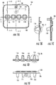
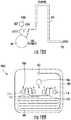
- Figures 1A-G illustrate an example cartridge 100 for use in evaluation of hemostasis in a subject.
- the cartridge 100 includes a front surface 101 and a rear surface 126.
- Figure 1A shows a front view of the cartridge 100 and the corresponding front surface 101.
- the cartridge includes an inlet 102, also referred to herein as an inlet port or entry port, such as a nipple, thought which a biological sample from the subject can be introduced into the cartridge.
- a blood sample from the subject is introduced into the cartridge at the inlet 102.
- Another biological sample that may be introduced for analysis is plasma.
- the inlet 102 is in fluid communication with a channel 202, which is shown in Figure 2 , and which directs the biological sample to other portions of the cartridge as described herein.
- the cartridge further includes a port 106 for applying a vacuum to the cartridge.
- a vacuum is applied at the port 106, the biological fluid introduced at the inlet 102 into the channel 202 the fluid is propelled along the channel 202 towards the port 106.
- channels 208, 210, 212 and 214 are in fluid communication with a test chamber, also referred to herein, for example, as a, chamber, well or test well or the like.
- a test chamber also referred to herein, for example, as a, chamber, well or test well or the like.
- channel 208 is in fluid communication with a test chamber 116
- channel 210 is in fluid communication with a test chamber 114
- channel 212 is in fluid communication with a test chamber 112
- channel 214 is in fluid communication with a test chamber 110.
- each test chamber comprises an open space 124 defined by a portion of the rear surface 126.
- Figure 1B shows a cross-sectional illustration through test chamber 116 taken across the line B-B of Figure 1A.
- Figure 1C shows a cross-sectional illustration taken across the line C-C of Figure 1A .
- Figure IF shows an expanded view of the circled portion of Figure 1B .
- Figure 1D shows a cross-sectional illustration across the line D-D of Figure 1A , which illustrates the open space of each of the four test chambers.
- Each test chamber is configured to accept a quantity of the biological fluid into the open space.
- a portion of the biological fluid introduced at the inlet 102 moves through the channels 202, 204 and 214 and into the open space 124 of the test chamber 116.
- the biological fluid can also exit each respective test chamber and continue along an exit channel 130 towards the port 106.
- fluid introduced at the inlet 102 flows under vacuum through the device channels and into the test chambers. From each test chamber (110, 112, 114, 116), the biological fluid continues to flow along exit channels towards the vacuum.
- each exit channel may direct the flowing biological fluid into a hydrophobic filter at location 222, 220, 218 and 216 respectively.
- the filters or filter prevents movement of the biological fluid out of the cartridge 100 at the port 106. Because the volume of the channels and the test chamber are fixed, the vacuum can pull the biological fluid into the cartridge until the channels and each test chamber is filled with the biological fluid.
- Pressure can be controlled within the cartridge 100 to, for example, manage flow rate within the consumable 100 and to mitigate reliability issues related to possible user misuse.
- a user of the hemostasis system optionally attaches a blood filled syringe to the cartridge 100 unit.
- the user of the hemostasis system 300 could attempt to inject the contents of the applied syringe into the cartridge 100 manually, instead of allowing the device to automatically aspirate the sample. This action may lead to measurement or system error.
- a pressure management device in the consumable flow path is used to prevent this user action.
- Rapidly aspirating the blood sample is optionally used to provide increased mixing of the reagents with the biological sample, such as a blood sample. This is optionally achieved by creating a pressure differential between the cartridge and the aspirating mechanism of the hemostasis system.
- Figures 9A-C illustrate three example configurations that can be used to control the pressure differential between the cartridge and the aspirating mechanism and can therefore be used to achieve desired levels of mixing and reduce user errors.
- FIG. 9A schematically illustrates an example system 900 for controlling pressure in a cartridge 100.
- the cartridge includes four test chambers (110, 112, 114 and 116). Each test chamber optionally includes a reagent and operation of the system causes a biological sample to enter one or more test chamber.
- the example system 900 includes a two way pump 908 which operates to aspirate a biological sample, such as a blood sample. For example, a blood sample can be aspirated into the cartridge from a sample container 902.
- the pump 908 is in fluid communication with the cartridge 100 and therefore activation of the pump can be used to move the biological sample through the cartridge 100.
- a pressure transducer 904 is in communication with the pump that measures the gauge pressure drawn by the pump 908.
- a solenoid actuated valve 906 operates to block flow downstream of the pump allowing gauge pressure to build.
- the solenoid may be selectively actuated to rapidly expose the pressure gradient to the cartridge.
- the sample is allowed to progress through the cartridge and is optionally collected in a sample container 910.
- FIG. 9B schematically illustrates another example system 920 for controlling pressure in a cartridge 100.
- the cartridge includes four test chambers (110, 112, 114 and 116). Each test chamber optionally includes a reagent and operation of the system causes a biological sample to enter one or more test chamber.
- the example system 920 includes a two way pump 908 which operates to aspirate a biological sample, such as a blood sample.
- a biological sample can be aspirated into the cartridge from a sample container 902.
- the pump 908 is in fluid communication with the cartridge 100 and therefore activation of the pump can be used to move the biological sample through the cartridge 100.
- a pressure activated membrane 912 is positioned either upstream or downstream of the cartridge 100 from the pump 908.
- the membrane 912 is configured to rupture at a predetermined cartridge gauge pressure thereby controlling the pressure at which the sample is drawn through the cartridge.
- the sample is allowed to progress through the cartridge and is optionally collected in a sample container 910.
- FIG 9C schematically illustrates another example system 930 for controlling pressure in a cartridge 100.
- the cartridge includes four test chambers (110, 112, 114 and 116). Each test chamber optionally includes a reagent and operation of the system causes a biological sample to enter one or more test chamber.
- the example system 930 includes a two way pump 908 which operates to aspirate a biological sample, such as a blood sample.
- a biological sample can be aspirated into the cartridge from a sample container 902.
- the pump 908 is in fluid communication with the cartridge 100 and therefore activation of the pump can be used to move the biological sample through the cartridge 100.
- a closed loop actuated valve 916 contains an internal pressure control mechanism and is used to block flow downstream from the pump allowing gauge pressure to build until a valve pressure setpoint. Once gauge pressure setpoint is reached the valve 916 deploys thereby exposing the cartridge to a desired pressure gradient.
- the sample is allowed to progress through the cartridge and is optionally collected in a sample container 910.
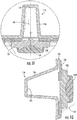
- FIG. 8A is a schematic illustration of an example consumable cartridge placed in an example hemostasis evaluation system.
- Figure 8B is a schematic illustration of a cross section taken across line B-B of Figure 8A.
- Figure 8C is an expanded schematic illustration of the circled portion of Figure 8B.
- Figure 8D is a schematic illustration of an example consumable cartridge.
- Whether a desired level has been reached in a given chamber can be indicated by a LED or other visual indicator.
- Employing a single light beam from an LED emitter 802 reflecting off the chamber at a blood detection target reservoir 224, which is then detected by a detector 800 can be optionally used to optically monitor chamber fluid level.
- blood entering a test chamber reduces reflection of light originating from an emitter 802 located alongside the detector 800, and pointed at the test chamber.
- a dual beam approach can be used whereby two sources of different wavelengths were reflected off the test chamber.
- Blood has a deep red color that can be differentiated by comparing the red wavelength reflection to that of another colour.
- the difference in intensity of the reflected red light alone is sufficient to determine when blood has entered a chamber.
- the red light intensity reflected from the test chamber containing blood was about one-half that of the well containing air, and about two-thirds of that from the well containing water.
- the cartridge 100 can comprise a heat exchanger in communication with the channel 204.
- the heat exchanger can be used to maintain, elevate or lower the temperature of the biological fluid before analysis in each test chamber.
- the temperature of biological fluid for analysis in each test chamber is the same such that common portion of the channel system, as shown in Figure 2 , is subject to temperature manipulation by the heat exchanger.
- the temperature of biological fluid entering each test chamber can be separately controlled.
- the biological fluid it can be passed through the channel 204 through a polystyrene labyrinth held against a copper block.
- the copper block can be thin (for example under 2 mm) and sized just larger than the labyrinth to minimize the thermal mass.
- a thermistor can be embedded in the block so that a control circuit could maintain a steady set temperature in the block.
- a heater is used that optionally comprises two Watlow® (St. Louis, MO) serpentine foil heating elements bonded to a flexible kapton plastic substrate, and the interface between the block and the heater can be a thin layer of silicone heatsink compound.
- Various flow rates for example, up to and including 5.99 ml/min or 6.0 ml/min can be used, and power input to the heater can be varied optionally between 8 and 16 Watts.
- Blood or other biological fluid can be heated in the cartridge from ambient temperature (approximately 20°C) to 37°C at a nominal flow rate of 6 ml/min, which is fast enough to fill the cartridge in 20 seconds.
- the surface area of the labyrinth used was less than 8 cm 2 .
- coagulation occurs at body temperature (37°C), which is optimal for the proper enzymatic action of the clotting factors in the cascade.
- Blood can be warmed from its incoming temperature, ranging between 18°C and 37°C, to an arbitrary or desired temperature, such as body temperature, of 37°C by passing through a serpentine channel in close proximity to a heater block. To accomplish the heating in a short time over a short path the block can be warmed to almost 60°C when the incoming blood is at the lower end of its temperature range.
- the temperature of the blood can also be measured and the heater block can optionally be adjusted to a temperature, ranging from 40°C to 58°C.
- a sensor can be incorporated in the system 300 ( Figure 5 ) or in the cartridge.
- a thermistor or thermocouple placed in physical contact with the cartridge or blood and an IR thermometer is pointed at the cartridge or blood.
- the cartridge may incorporate a small well through which the incoming blood passes, rather than having direct contact with the blood.
- the cartridge's material polystyrene
- the larger heat capacity of the blood ensures the well's wall temperature is close to that of the blood.
- a window allowing the passage of IR is used.
- the window can comprise a thin layer (e.g. 20um or less) of polyethylene or polystyrene.
- Temperature changes can occur in the body due to fever or in hospital settings such as the emergency room (ER) or operating room (OR). Trauma patients arriving at the ER are treated with large volumes of intravenous saline, which lowers body temperature to as much as 17°C. In the OR, patients undergoing cardiac bypass surgeries (CPB) have their entire blood volume pass through a lung-heart machine, which also lowers blood temperature and can adversely affect coagulation. Also, if there is a lag of time between the time of blood draw and the measurement, the temperature of blood is given time to change.
- CPB cardiac bypass surgeries
- Styron® 666 (Styron Inc. Berwyn, PA) polystyrene and the microfluidic heat exchanger channel 204 allows a blood sample to be warmed by a copper block outside of the cartridge that is kept at a constant 37°C.
- a sample enters the cartridge at temperatures substantially lower than 37°C, it is optionally desirable to use a cartridge modified to allow for more rapid heating of the biological sample.
- Styron® 666 was found to reduce ability to heat blood and the blood exiting the heat exchanger did not reach 37°C .
- the cartridge can include materials with higher thermal conductivity than Styron® 666.
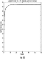
- a thermally conductive polymer (E1201®) from Cool Polymers Inc. (North Kingstown, RI) with improved thermal conductivity properties can be used.
- This polymer can form a portion of the cartridge between the heating block and the channel 204.
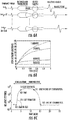
- FIG. 11 shows that in a cartridge comprising this material blood entering the heat exchanger at 17°C reaches 37°C within 15 seconds.
- Cartridges optionally include both materials, EI 201® and Styron® 666, in order to improve the heat transfer to the sample with El 201® on the heated side while maintaining flow visibility on the other side of the consumable with the Styron® 666.
- EI 201® and Styron® 666 Another alternative is to use El 201® as an insert that fits over the copper heater and into a chassis made out of Styron® 666. This is optionally accomplished by overmolding the separate pieces into one single piece or affixing the El 201® to the Styron® chassis by means such as laser, ultrasonic or RF welding. Changing the geometry of the El 201® insert to fit into the larger chassis as a puzzle piece can further improve assembly of the separate parts and help seal the micro fluidic flow chambers.
- the cartridge can include materials with higher thermal conductivity than Styron® 666.
- the thermally conductive polymer E1201®
- This polymer can form a portion of the cartridge between a cooling device, such as a peltier cooling device, and the channel 204. Using this polymer in a portion of the cartridge between the cooling device and sample, the sample can be efficiently cooled.
- Each test chamber comprises one or more reagents useful in the analysis of one or more indices of hemostasis.
- the reagents are lyophilized.
- one or more lyophilized bead type reagent is used.
- the lyophilized bead can be a LyoSphere® produced by BioLyph (Minnetonka, MN).
- a self-contained lyophilized bead is a format that allows for immunochemical and clinical chemistry reagents requiring two or three components that are incompatible as liquids because of their pH level or reaction to one another to coexist compatibly. Because such lyophilized beads are stable and nonreactive, chemicals can be packaged together in the same test chamber.
- a lyophilizer device can be used.
- the reagent for a given test chamber can be frozen to solidify all of its water molecules. Once frozen, the product is placed in a vacuum and gradually heated without melting the product. This process, called sublimation, transforms the ice directly into water vapor, without first passing through the liquid state.
- the water vapor given off by the product in the sublimation phase condenses as ice on a collection trap, known as a condenser, within the lyophilizer's vacuum chamber.
- the lyophilized product contains 3% or less of its original moisture content.
- the lyophilized product which may be a pellet, can then be positioned in each test chamber. Once placed in a test chamber, the test chamber can be sealed to prevent unwanted rehydration of the product.
- the components can first be lyophilized and then the resulting lyophilized product can be placed in the test chambers. Using UV cure epoxy glue or a welding process (such as ultrasound or RF welding), the lens assembly is sealed over each of the test chambers.
- the assembled cartridge can be sealed in a vapor proof barrier (e.g. a bag) and the vapor barrier can be sealed to preserve the dehydrated nature of the product in the test chambers.
- the cartridge can be removed from the bag or vapor barrier and placed into an analysis system 300, which is described in further detail below.
- Lyophilized reagents are inherently devoid of water, granting them significant electrical insulation.
- Air ionization is a method that passes directed, ionized air over a target material to neutralize residual static charge on the material surface. Directing ionized air at one or more cartridge test chamber and/or the reagents during the assembly process improves manufacturability by reducing the adherence of the reagent bead to the cartridge test chambers.
- a second method implements cartridge construction using a plastic material that exhibits significantly more conductivity than standard injection molding materials.
- RTP PermaStat® (Winona, MA) plastics are an example of such materials.
- the use of this material for the cartridge reduces the adhesion of the lyophilized reagents to the cartridge test chamber walls.
- Third anti-static, liquid sprays are used to temporarily create a dust-free coating on optical lenses and equipment. These sprays reduce static charge on the target surface and are useful for static reduction during the cartridge assembly process.
- the consumable cartridge 1002 optionally comprises a fluidic circuit 202 that delivers the sample from an external vessel, such as a syringe or vacutainer, into one or more test chambers (110, 112, 114, 116) were measurements are performed.
- an external vessel such as a syringe or vacutainer
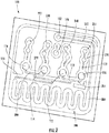
- FIG. 10A shows an example fluidic circuit that can be implemented in a consumable cartridge 1002.
- This circuit includes an entry port 102, a channel 202, four test chambers (110, 112, 114, 116), a filter 1004 and an exit port 1006.
- the biological sample can be delivered within the chamber by applying a vacuum at the exit port, with the filter allowing air to escape but stopping the fluid.
- a variety of different reagents can be placed within the test chamber, for example, as described throughout. In order to generate accurate measurements, the reagents are mixed within the sample before testing is initiated. For example, ultrasound emitted into the test chambers can be used to mix the reagents with the sample as described below.
- a biological fluid sample can flow through the channel 202, which enters the test chamber at the side on a tangent to the chamber. Furthermore, the change in channel diameter from large to small increases the flow velocity (conservation of flow rate) at the entrance to the test chamber. This high flow velocity, in collaboration with gravity, helps generate a re-circulating rotational flow pattern that improves mixing and reagent dispersion with the sample. As the flow enters from the side, it causes any formed foam to be pulled into the flow stream and pushed below the surface.
- FIG. 10B shows a flow pattern implemented in a consumable cartridge designed for injection molding.
- the fluidic circuit has been repeated four times in order to deliver the sample and mix reagents in four different test chambers.
- the circuit presented in FIG. 10B also includes a serpentine heat exchanger to adjust the temperature of the incoming sample to a desired level.
- Reagents are mixed with the sample before testing is initiated.
- Mixing of the reagents can be accomplished using passive and/or active mechanisms.
- Passive methods include, for example, the use of serpentine channels and embedded barriers to create flow turbulence.
- Active methods include, for example, magnetic beads, pressure perturbation, and artificial cilia.
- the consumable cartridge contains a lens that focuses ultrasound energy within the sample that can be used to generate streaming and mixing.
- the lens also referred to herein as a lens assembly, or sound focusing assembly, is designed using a soft material, such as a thermoplastic elastomer 134, in conjunction with a rigid substrate 132, such as polystyrene. This combination provides a dry ultrasound coupling that does not require the use of any fluid or gel couplant. Note that the same lens and ultrasound driver used for hemostasis measurement can be used in this matter to provide mixing. Increasing acoustic energy for mixing can be delivered by, for example, increasing pulse length, pulse amplitude or pulse repetition frequency.
- Mixing can also be provided by a variable magnetic field applied by a series of coils placed outside a test chamber or each test chamber.
- a small magnetic bead or magnetic stirrer can be placed within a test chamber and when the fluid sample enter the chamber, the current across the coils can be modulated in order to generate a variable magnetic field. This generates motion of the magnetic bead or magnetic stirrer which in turns generates mixing of the sample with the reagent.
- test well(s) and/or channel(s) of a consumable cartridge are coated with such surface proteins for the measurement of coagulation within a POC medical device.
- surface protein coatings includes collagen, vWF, fibronectin and any other molecule that modulates coagulation such as fibrinogen and thrombin.
- a layer of protein on a substrate creates binding sites that allow the mediation of receptor-ligand interactions between the substrate and other biological materials such as blood in a manner that improves the assessment of coagulation or provides new testing information.
- the interior surfaces of a consumable cartridge can be coated using for example: (1) a layer of such proteins by covalent binding using linker molecules, (2) covalent binding using photochemistries or (3) simple protein adsorption.
- Linker molecules such as streptavidin or avidin and biotin can be used for this purpose.
- the surface of any interior portion of the cartage that will be exposed to the biological sample is biotinylated (coated with a layer of biotin) using commercially available biotin that is conjugated to a reactive group that non-specifically and covalently binds with the substrate.
- a solution with a high concentration of streptavidin or avidin, which have high affinity for biotin is added to create a layer of streptavidin/avidin bound biotin.
- Addition of biotinylated protein (collagen, vWF, fibronectin, thrombin, fibrinogen) then creates a layer of protein bound to the test well surface that specifically affects coagulation through interactions with plasma proteins and
- Protein adsorption can be accomplished by filling the wells with a highly concentrated protein solution. Adsorption to the plastic surface takes place almost immediately depending on temperature, ph, surface charges, surface morphology and chemical composition. The solution can then be removed and the surface air dried. Brushing a highly concentrated protein solution on the surface of the wells or dipping the wells into such a solution will accomplish the same purpose.
- the concentration of molecules in the solutions used for coating can be changed to modulate the amount of protein that binds the substrate and, thus, modulate the effects on the coagulation cascade in a way that is relevant to physiology and hemostasis.
- a lens assembly 131 includes a rigid substrate 132 and a couplant 134 that can be positioned at the back end of each test chamber.
- Each couplant 134 comprises an elastomeric material.
- the elastomeric material is a thermoplastic elastomer (TPE).
- TPE thermoplastic elastomer
- Example elastomeric materials optionally include, Dynaflex D3202, Versaflex OM 9-802CL, Maxelast S4740, RTP 6035.
- the couplant is over-molded to the rigid substrate.
- each couplant 134 and the open space of each test chamber is a rigid substrate 132.
- the rigid substrate and the couplant form an interface that focuses ultrasound transmitted (e.g. lens assembly) by an ultrasonic transducer into the chamber's open space and onto any biological fluid and/or reagents in the chamber.
- the rigid substrate of the lens can comprise a material which allows sound to pass and that can act to focus ultrasound at some level within the space.
- the rigid substrate comprises a styrene, such as, for example Styrene® 666.
- the lens assembly may be glued or welded to the surface 101 to secure the lens in place in an orientation that allows the desired focusing of sound.
- the lens assembly is optionally manufactured together with the surface 101.
- the rigid substrate 132 can be molded with the surface 101 and the couplant 134 can be overmolded on the rigid substrate.
- materials can be used to construct the device. For example, plastics can be used for single use, disposable cartridges.
- Each test chamber (116, 114, 112 and 110) can have a lens assembly positioned over the large opening of each chamber's open space. In this way, each chamber can be separately interrogated by focused ultrasound.
- the couplant 134 When placed in the analysis system 300, the couplant 134 can be placed in acoustic communication with a transducer for supplying ultrasound through the lens assembly and into a test chamber.
- an intermediate layer of an acoustically permeable material is positioned between an ultrasonic transducer and the couplant.
- intermediate layer or block of Rexolite® can be used. The intermediate layer can be forced against the couplant and can be in acoustic contact with the transducer.
- Sound generated by a transducer passes through the intermediate layer, through the couplant, through the rigid substrate, and is focused within the biological sample and reagent in the test chamber.
- Some of the sound directed into chamber contacts the distal interior surface 111 of the test chamber, which is defined by the surface 126.
- the surface is polystyrene.
- the distal interior surface has a know geometry and is positioned at a know distance from the ultrasound source.
- the distal interior surface 111 is used as a calibrated reflector, which is used to estimate the speed of sound and attenuation of sound in a test chamber at base line and during the process of clot formation and clot dissolution.
- the sound generated by the transducer can be focused within the biological sample in a test chamber using a parabolic mirror that is coupled to the biological sample using an elastomer.
- Figure 12A illustrates an example geometry for a parabolic mirror that can be used to focus sound into one or more test chamber, wherein f(x,y) is the shape of the focusing reflector, z 0 is the height of the reflector above the active element at the origin, and (x f , y f , z f ) is the coordinate of the focal point.
- the focusing reflector is defined by a curve which is equidistant from the emitting point on the active acoustic element and the focal point.
- d f x y + x f ⁇ x 2 + y f ⁇ y 2 + z f ⁇ f x y 2
- d the total distance from the face of the acoustic source to the focus.
- Equation 2 above can be evaluated and substituted into equation 10 above to yield an equation for the surface of the reflector.
- the reflector is a parabolic section.
- Example parameters are optionally an 8mm aperture with a focus at 16 mm laterally, 4mm in range and with an offset between the mirror and aperture of 0.5mm.
- a diagram of this geometry is shown in Figure 12B . This geometry is useful where the focusing mirror is placed within the system. The mirror can also be placed within the cartridge. In this case, the focus is optionally moved closer in the axial dimension, but further in the lateral dimension as shown in Figure 12C .
- the cartridge 100 can be positioned into pocket 302 of an analysis system 300.
- the pocket includes an actuator system 402 for pressing the intermediate layer, such as Rexolite®, that is acoustically coupled to a transducer into contact with the couplant 134.
- the pocket holds the cartridge in securely in place and in an orientation such that ultrasound can be focused into each testing chamber.
- FIG. 5 shows further aspects of the cartridge 100 positioned in the analysis system.
- the cartridge is positioned such that the intermediate layer 504 is pushed into the couplant 134, which is in communication with the rigid substrate 132 of the lens assembly 131.
- Ultrasonic generating means 502, including at least one ultrasonic transducer are positioned such that ultrasound is transmitted through the intermediate layer, lens assembly, and into the test chamber.
- At least a portion of the sound is reflected by the biological sample positioned therein the chamber, and a portion of the sound transmitted into the chamber can also be reflected from the chamber distal surface 111.
- the reflected ultrasound can be received by the ultrasonic transducer and transmitted to the system for processing.
- the cartridge and the analysis system 300 may be in communication such that data and other operational or processing signals may be communicated between the cartridge and the analysis system.
- a suitable analysis system 300 can therefore comprise one or more processing devices.
- the processing of the disclosed methods, devices and systems can be performed by software components.
- the disclosed systems, devices, and methods, including the analysis system 300 can be described in the general context of computer-executable instructions, such as program modules, being executed by one or more computers or other devices.
- program modules comprise computer code, routines, programs, objects, components, data structures, etc. that perform particular tasks or implement particular abstract data types.
- the program modules can be used to cause the transmission of ultrasound having desired transmit parameters and to receive and process ultrasound to evaluate hemostasis indices of a sample from the subject.
- the software can also be used to control the heating of the biological sample using the heat exchanger and to monitor and indicate the fill level of a given chamber.
- the processor can also be used to perform algorithms, to determine hemostatic indices and hematocrit.
- the software can be used to back-out determined hematocrit from determined hemostatic indices.
- the determined hemostatic indices and hematocit can be displayed to a medical professional or medical agent for the purpose of making medical decisions for a subject.
- the systems, devices, and methods disclosed herein can be implemented via a general-purpose computing device in the form of a computer.
- the computer or portions thereof, may be located in the analysis system 300.
- the components of the computer can comprise, but are not limited to, one or more processors or processing units, a system memory, and a system bus that couples various system components including the processor to the system memory.
- the system can utilize parallel computing.
- the computer typically comprises a variety of computer readable media. Exemplary readable media can be any available media that is accessible by the computer and comprises, for example and not meant to be limiting, both volatile and non-volatile media, removable and non-removable media.
- the system memory comprises computer readable media in the form of volatile memory, such as random access memory (RAM), and/or non-volatile memory, such as read only memory (ROM).
- RAM random access memory
- ROM read only memory
- the system memory typically contains data such as data and/or program modules such as operating system and software that are immediately accessible to and/or are presently operated on by the processing unit.
- the computer can also comprise other removable/non-removable, volatile/non-volatile computer storage media.
- a mass storage device which can provide non-volatile storage of computer code, computer readable instructions, data structures, program modules, and other data for the computer.
- a mass storage device can be a hard disk, a removable magnetic disk, a removable optical disk, magnetic cassettes or other magnetic storage devices, flash memory cards, CD-ROM, digital versatile disks (DVD) or other optical storage, random access memories (RAM), read only memories (ROM), electrically erasable programmable read-only memory (EEPROM), and the like.
- any number of program modules can be stored on the mass storage device, including by way of example, an operating system and software.
- Each of the operating system and software, or some combination thereof, can comprise elements of the programming and the software.
- Data can also be stored on the mass storage device.
- Data can be stored in any of one or more databases known in the art. Examples of such databases comprise, DB2®, Microsoft® Access, Microsoft® SQL Server, Oracle®, mySQL, PostgreSQL, and the like.
- the databases can be centralized or distributed across multiple systems.
- the user can enter commands and information into the computer via an input device.
- input devices comprise, but are not limited to, a keyboard, pointing device (e.g., a "mouse"), a touch screen, a scanner, and the like.
- pointing device e.g., a "mouse”
- touch screen e.g., a scanner
- input devices can be connected to the processing unit via a human machine interface that is coupled to the system bus, but can be connected by other interface and bus structures, such as a parallel port, game port, an IEEE 1394 Port (also known as a Firewire port), a serial port, or a universal serial bus (USB).
- USB universal serial bus
- a display device 304 such as a touch screen
- a display adapter can also be connected to the system bus via an interface, such as a display adapter.
- the computer can have more than one display adapter and the computer can have more than one display device.
- a display device can be a monitor, an LCD (Liquid Crystal Display), or a projector.
- Computer readable media can be any available media that can be accessed by a computer.
- Computer readable media can comprise computer storage media and communications media.
- Computer storage media comprise volatile and non-volatile, removable and non-removable media implemented in any method or technology for storage of information such as computer readable instructions, data structures, program modules, or other data.
- the reagents in each test chamber can include all the reagents needed for evaluating one or more indices of hemostasis.
- the cartridge is a single use, disposable cartridge with pre-loaded lyophilized reagents.
- the cartridge can be used with whole blood from a subject.
- the cartridge or assay components include the following for fresh whole blood samples. Four separate wells containing lyophilized reagents to which 1.6 ml of fresh whole blood is added.
- test well utilizes around 300 ⁇ l of fresh whole blood along with the following reagents: Table 1: Test We ll 1 Test Well 2 Test Well 3 Test Well 4 0.15 mg of kaolin 0.15 mg of kaolin 0.3 U of thrombin recombinant tissue factor buffers and stabilizers buffers and stabilizers buffers and stabilizers buffers and stabilizers buffers and stabilizers 0 ⁇ l of 2mg/ml abciximab 12 ⁇ l of 2mg/ml abciximab 12 ⁇ l of 2mg/ml abciximab 0 ⁇ l of 2mg/ml abciximab
- the devices systems and methods use the phenomenon of acoustic radiation force to measure changes in mechanical properties (e.g. stiffness) of a blood sample during the processes of coagulation and fibrinolysis. These changes are representative of the role of the four key components of hemostasis: (i) plasma coagulation factors, (ii) platelets, (iii) fibrinogen, and (iv) fibrinolytic factors of the plasma.
- the basic approach is shown in Figures 6A-C .
- a series of N focused ultrasound pulses are sent into a blood sample at short intervals ⁇ T ( ⁇ T is on the order of microseconds), as shown schematically in panel A.
- ⁇ T is on the order of microseconds
- Each pulse generates a small and localized force within the blood as acoustic energy is absorbed and reflected during propagation. This force, which is concentrated around the focus of the ultrasound beam, induces a small displacement within the blood sample that depends upon the local mechanical properties. These displacements are on the order of 40 micrometers or less at the focus of the ultrasound beam.
- Each pulse also returns an echo, as a portion of its energy is reflected from within the blood sample. Because the sample moves slightly from one pulse transmission to the next, the path length between the fixed ultrasound emitter and any given region within the target increases with pulse number. This change in path length can be estimated from differences in the arrival times of echoes from the same region.
- the ensemble of these delays forms a time- displacement curve that holds combined information about viscoelastic properties of the sample. These time-displacement curves are shown in Figure 6B . These time-displacement curves are measured every 6 seconds to fully characterize the dynamics of coagulation and fibrinolysis, representing the entire hemostatic process.
- the application of the acoustic force When the blood sample is in a viscous fluid state, the application of the acoustic force generates large displacements. As coagulation is activated and fibrinogen is cross-linked into fibrin strands, the sample behaves as viscoelastic solid and the induced displacement reduce as the stiffness of the sample increases. The interaction of platelets and the fibrin mesh also further reduce the induced displacements as the clot's stiffness increases. As the clot progresses into the phase of fibrinolysis, the fibrin mesh is dissolved by the fibrinolytic enzymes and the sample returns to viscous fluid, exhibiting increasing displacements.
- Acoustic radiation force results from the transfer of momentum that occurs when a propagating acoustic wave is either absorbed or reflected.
- the acoustic energy used by the instrument to generate acoustic radiation force is comparable with the acoustic energy typically used for common medical ultrasound procedures such as color Doppler imaging.
- the estimated maximum acoustic intensity is on the order of 2.5 W/cm 2 (time average), which results in a temperature increase of the blood sample of 0.01°C for each measurement ensemble (performed roughly every 6 seconds).
- the applied acoustic radiation force is adaptively changed to induce displacements above the noise threshold, but below levels that could induce mechanical disruption (typically below 40 micrometers).
- the magnitude of the force is adjusted to follow the changes in mechanical properties of the blood sample by varying the time interval ⁇ T between successive pulses, as shown in equation 1.
- the maximum displacement induced during the (m-1)th acquisition is used to determine whether the force should be increased or decreased for the mth acquisition, based on predetermined threshold values. This adaptive process allows characterization of five orders of magnitude in stiffness without generating high strain within the blood sample that could alter the dynamics of coagulation and fibrinolysis.
- the applied acoustic radiation force changes as a function of acoustic attenuation and speed of sound, both of which change as a function of coagulation.
- the system uses the echoes returning from within the cartridge to estimate changes in these parameters and normalize the acoustic radiation force.
- Acoustic radiation force is generated using conventional piezoelectric materials that act as acoustic emitters and receivers. These materials deform when a voltage is applied across them, and conversely generate a voltage when they are deformed. Similar to optics, an acoustic lens can be placed in front of the piezoelectric material to focus acoustic energy on a single focal point.
- piezoelectric disks are used that have an active diameter of 7.5 mm.
- the acoustic lens is provided by the curved shape of the disposable cartridge.
- Four disks are placed side by side to send sound in the four test wells in a disposable cartridge.
- the frequency of vibration of these piezoelectric disks is centered at 10 MHz, well within the range of frequencies used in conventional ultrasound imaging.
- Ultrasound echo signals returning to the transducers from the blood samples are first filtered to remove electronic noise, digitized, and further processed within an embedded processor in the system.
- a flow chart of the data analysis steps performed by the system is shown in Figure 7 where a test starts at block 700. Ultrasound pulses are transmitted into a target sample in a test well at 702. Echoes are received, filtered and digitized at 704. After a short wait 706, steps 702 to 704 can be repeated. A time delay estimation is applied at 708 and an curve fitting at 710. The system then determines if enough data has been acquired to estimated the desired indexes of hemostasis at 712. If there is enough data to estimate a hemostasis index, the hemostasis index is estimated and 714 and displayed at 716.
- the system determines if the test should be stopped at 718 and, if so, an output summary is generated at 722. If the test is to continue, after a long wait 770, one or more steps 702-770 are optionally repeated.
- time delay estimation is performed to estimate a local time- displacement curve, similar to that shown in Figure 6B .
- TDE entails measuring the relative time shift from one received echo to the next; the known value of the speed of sound in blood allows conversion of the time shifts into displacements.
- TDE is performed around the focus of the ultrasound beam. This process is repeated every 6 seconds (arbitrary fixed wait) to obtain time- displacement curves throughout the process of coagulation and fibrinolysis.
- TDE is a common signal processing step in application fields ranging from RADAR, SONAR, and medical ultrasound imaging (Doppler).
- the viscoelastic properties of the blood sample during hemostasis are modeled using a modified model consisting of the well-known Voigt-Kelvin mechanical model with the addition of inertia. While the dynamic changes in viscoelasticity of blood during hemostasis are certainly complex, the modified Voigt-Kelvin model is simple and robust, and it has been well validated in the past.
- Each time-displacement curve is fitted to the characteristic equation of the modified Voigt-Kelvin model to estimate a variety of parameters relating to the viscoelastic properties of the sample. These parameters include relative elasticity, relative viscosity, time constant, and maximum displacement.
- the system uses the estimated displacement magnitude at 1 second as a qualitative measure of the stiffness of the sample.
- the displacement at 1 second is high.
- the blood coagulates this displacement decreases proportionally to the generation of the fibrin mesh and activity of platelets. The value increases again during the process of fibrinolysis.
- Indices of hemostasis are calculated by fitting a sigmoidal curve to the stiffness-time curve ( Figure 6C ) and evaluating the first derivative of the curve.
- the times to clot TC1 and TC2 are calculated based on a threshold value of the derivative curve (20% of the minimum value), and are indicative of the beginning and ending phase of fibrin polymerization.
- the clotting slope CFR is the maximum of the derivative curve and is indicative of the rate of fibrin polymerization.
- the stiffness S is estimated from the stiffness curve 3 minutes after TC2. S depends upon platelet function and the final stiffness of the fibrin network. Identical methods and indices are calculated for the fibrinolytic process.
- the times TL1 and TL2 can be defined to represent the initial and final phases of the fibrinolytic process and the consequent dissolution of the fibrin network (time to lysis).
Description
- This application claims the benefit of
U.S. Provisional Application Nos. 61/443,088, filed on February 15, 2011 - The present application relates to devices, systems and methods for evaluating hemostasis in a subject by analysis of a test sample from the subject to determine one or more indices of hemostasis.
- Hemostasis, the physiological control of bleeding, is a complex process incorporating the vasculature, platelets, coagulation factors (FI-FXIII), fibrinolytic proteins, and coagulation inhibitors. Disruption of hemostasis plays a central role in the onset of myocardial infarction, stroke, pulmonary embolism, deep vein thrombosis and excessive bleeding. Consequently, in vitro diagnostics (IVD) are critically needed to quantify hemostatic dysfunction and direct appropriate treatment. This need is particularly acute during cardiac surgeries requiring cardiopulmonary bypass (CPB), where post-surgical bleeding is a common complication requiring transfusion of blood products.
- Existing IVDs include endpoint biochemical assays, platelet aggregation assays, and clot viscoelastic measurement systems. Endpoint biochemical assays such as the prothrombin time (PT) and the partial thromboplastin time (PTT) are widely used to assess coagulation. However, these tests measure only a part of the hemostatic process and operate under non-physiological conditions incorporating only the function of plasma. As a result of these limitations, complications such as postoperative bleeding often occur despite normal perioperative PT and PTT measurements.
- Activated clotting time (ACT) is an endpoint assay that is most often applied in support of CPB. This assay applies strong initiation of the surface activation (intrinsic) pathway to quantify heparinization. Limitations of the ACT include its disregard for platelet function, lysis, and coagulation kinetics along with the use of large aliquots of whole blood (WB) (generally 2 mL) and moving mechanical parts. For these reasons, the ACT is used for rapid assessment of heparinization and associated protamine reversal with limited utility for additional applications.
- Platelets play a crucial role in the progression of coagulation and quelling arterial bleeding. Furthermore, the modern cell-based theory of hemostasis recognizes that platelets play a modulating role in coagulation. Platelet function is monitored clinically via both central lab assays and point of care (POC) tests, which use anticoagulated WB. Both approaches are limited in that they use platelet aggregation as a proxy for overall platelet function. Furthermore, disabling coagulation, these methods neglect the interaction between platelets and the coagulation cascade.
- Techniques that monitor the viscoelastic properties of WB, such as thromboelastography (TEG) and rotational thromboelastometer (ROTEM), circumvent many of the limitations of endpoint biochemical assays and platelet aggregation assays by measuring the combined effects of all components of hemostasis. TEG has been shown to diagnose hyperfibrinolysis in bleeding patients, indicate transfusion requirements better than standard biochemical assays, and reduce transfusion requirements during CPB when used with transfusion algorithms. While these tests offer valuable clinical information, the devices are typically complex to operate and difficult to interpret. Moreover, the TEG applies relatively large shear strains, which transgress the non-linear viscoelastic regime, thereby disrupting clot formation. For these reasons, the TEG sees very limited utility as a POC test.
- "A novel ultrasound-based method to evaluate hemostatic function of whole blood", Clinica Chimica Acta 411 (2010) 106-113 , Francesco Viola, F. William Mauldin Jr., Xiefan Lin-Schmidt, Doris M. Haverstick, Michael B. Lawrence, William F. Walker, discloses sonorheometry, which can assess hemostasis function from a small sample of blood. Sonorheometry uses the phenomenon of acoustic radiation force to measure the dynamic changes in bood viscoelasticity during clot formation and clot dissolution.
-
US 5,629,209 discloses apparatus for detecting changes in the viscosity of a fluid, comprising a cartridge having a fluid receiving/dispensing reservoir, one or more fluid-receiving chambers, and a conduit that permits fluid communication between the fluid receiving/dispensing reservoir and the fluid-receiving chamber. -
US2011034805 discloses methods, apparatus and systems for characterizing at least one physical property of blood, by generating a series of acoustic pulses and directing the series of pulses into the blood such that at least one of the pulses is of sufficiently high intensity to induce physical displacement of the blood. Acoustic pulses and/or optical waves reflected from the blood, or a flexible member in contact with the blood that moves with the blood, are received and measured to estimate at least one characteristic of the physical displacement induced thereby. -
WO2011127436 discloses a system for displaying a plurality of hemostatic indexes. The system includes a communication receiver configured to receive the hemostatic indexes and a graphical user interface (GUI) connected to the communication receiver and to simultaneously display the hemostatic indexes. The hemostatic indexes are derived from a plurality of independent measurements, such as the mechanical measurements determined using the sonorheometry systems and processes. - Provided are systems and methods for evaluation of hemostasis. According to an aspect of the invention there is provided a device for evaluation of hemostatis as claimed in
claim 1. In an embodiment, the reagents are selected from the group consisting of kaolin, celite, glass, abciximab, cytochalasin D, thrombin, recombinant tissue factor, reptilase, arachidonic acid (AA), adenosine diphosphate (ADP), and combinations thereof. Optionally, the reagents are lyophilized prior to interacting with the test samples. - The system comprises a transducer for transmitting ultrasound into one or more chamber and for receiving reflected sound from the chamber and the test sample therein. The system further comprises at least one processor configured to determine a hemostasis parameter from the received sound. The parameters are optionally selected from the group consisting of TC1, TC2, clot stiffness, clot formation rate (CFR), TL1 and TL2. The processor is optionally further configured to determine an intrinsic pathway coagulation factors index, an extrinsic pathway coagulation factors index, a platelets index, a fibrinogen index, and a fibrinolysis index value. The intrinsic and extrinsic coagulation factors are optionally combined to form a coagulation factors index.
- According to another aspect of the invention there is provided a method as claimed in claim 11. The parameters are optionally selected from the group consisting of TC1, TC2, clot stiffness, clot formation rate (CFR), TL1 and TL2. The disclosed methods can further include determining an intrinsic pathway coagulation factors index, an extrinsic pathway coagulation factors index, a platelets index, a fibrinogen index, and a fibrinolysis index value. The intrinsic and extrinsic coagulation factors are optionally combined to form a coagulation factors index. The reagents or combinations thereof are optionally lyophilized prior to mixing with the blood.
- These and other features and advantages of the present invention will become more readily apparent to those skilled in the art upon consideration of the following detailed description and accompanying drawings, which describe both the preferred and alternative embodiments of the present invention.
-
-
FIGs. 1A-G are schematic illustrations of an example cartridge for evaluating hemostasis. -
FIG. 2 is a schematic illustration of biological fluid pathways of the example cartridge ofFIGs. 1A-G . -
FIG. 3 is a schematic illustration of an example processing system for use with the example cartridge ofFIGs. 1A-G . -
FIG. 4 is a schematic illustration of a portion of a system for evaluating hemostasis. -
FIG. 5 is a schematic illustration of a portion of a system for evaluating hemostasis. -
FIG. 6A is a schematic illustration showing N acoustic pulses are sent into a blood sample to generate a force. The resulting deformation can be estimated from the relative time delays between the N returning echoes. -
FIG. 6B is a graph showing example displacement curves generated within a blood sample. As blood clots, reduced displacement is observed. -
FIG. 6C is a graph showing displacements combined to form graphs of relative stiffness, which characterize the hemostatic process. The parameters described in panel are estimated from parameters found by fitting a sigmoidal curve. -
FIG. 7 is a flow diagram illustrating an example method to estimate hemostasis parameters. -
FIGs. 8A-D are schematic illustrations of an example cartridge for evaluating hemostasis. -
FIGs. 9A-C are schematic illustrations of portions of a system for evaluating hemostasis including pressure control mechanisms. -
FIGs. 10A and 10B are schematic illustrations of an example sample flow pattern for use with the described devices and systems and of an example cartridge for evaluating hemostasis. -
FIG. 11 is a graph showing data of heating of blood within an example cartridge for evaluating hemostasis. -
FIGs. 12A-C are schematic illustrations of example sound focusing mechanisms. - The present invention now will be described more fully hereinafter with reference to specific embodiments of the invention. Indeed, the invention can be embodied in many different forms and should not be construed as limited to the embodiments set forth herein; rather, these embodiments are provided so that this disclosure will satisfy applicable legal requirements.
- As used in the specification, and in the appended claims, the singular forms "a," "an," "the," include plural referents unless the context clearly dictates otherwise.
- The term "comprising" and variations thereof as used herein are used synonymously with the term "including" and variations thereof and are open, non-limiting terms.
- As used throughout, by a "subject" is meant an individual. The subject may be a vertebrate, more specifically a mammal (e.g., a human, horse, pig, rabbit, dog, sheep, goat, non-human primate, cow, cat, guinea pig or rodent), a fish, a bird or a reptile or an amphibian. The term does not denote a particular age or sex.
-
Figures 1A-G illustrate anexample cartridge 100 for use in evaluation of hemostasis in a subject. Thecartridge 100 includes afront surface 101 and arear surface 126.Figure 1A shows a front view of thecartridge 100 and the correspondingfront surface 101. The cartridge includes aninlet 102, also referred to herein as an inlet port or entry port, such as a nipple, thought which a biological sample from the subject can be introduced into the cartridge. Optionally, a blood sample from the subject is introduced into the cartridge at theinlet 102. Another biological sample that may be introduced for analysis is plasma. Theinlet 102 is in fluid communication with achannel 202, which is shown inFigure 2 , and which directs the biological sample to other portions of the cartridge as described herein. - The cartridge further includes a
port 106 for applying a vacuum to the cartridge. When a vacuum is applied at theport 106, the biological fluid introduced at theinlet 102 into thechannel 202 the fluid is propelled along thechannel 202 towards theport 106. - As shown in
Figure 2 , in moving between theinlet 102 and theport 106, the biological fluid, or a portion thereof, moves along thechannel 202, into thechannel 204, thechannel 206, and along thechannels channels Figure 2 ,channel 208 is in fluid communication with atest chamber 116,channel 210 is in fluid communication with atest chamber 114,channel 212 is in fluid communication with atest chamber 112, andchannel 214 is in fluid communication with atest chamber 110. - Referring again to
Figure 1 , each test chamber comprises anopen space 124 defined by a portion of therear surface 126.Figure 1B shows a cross-sectional illustration throughtest chamber 116 taken across the line B-B ofFigure 1A. Figure 1C shows a cross-sectional illustration taken across the line C-C ofFigure 1A . Figure IF shows an expanded view of the circled portion ofFigure 1B . Moreover,Figure 1D shows a cross-sectional illustration across the line D-D ofFigure 1A , which illustrates the open space of each of the four test chambers. - Each test chamber is configured to accept a quantity of the biological fluid into the open space. In reference to test
chamber 116, illustrated in detail in Figure IF, a portion of the biological fluid introduced at theinlet 102 moves through thechannels open space 124 of thetest chamber 116. - The biological fluid can also exit each respective test chamber and continue along an
exit channel 130 towards theport 106. Thus, fluid introduced at theinlet 102 flows under vacuum through the device channels and into the test chambers. From each test chamber (110, 112, 114, 116), the biological fluid continues to flow along exit channels towards the vacuum. - Proximate the
port 106 each exit channel may direct the flowing biological fluid into a hydrophobic filter atlocation cartridge 100 at theport 106. Because the volume of the channels and the test chamber are fixed, the vacuum can pull the biological fluid into the cartridge until the channels and each test chamber is filled with the biological fluid. - Pressure can be controlled within the
cartridge 100 to, for example, manage flow rate within the consumable 100 and to mitigate reliability issues related to possible user misuse. To measure the properties of a target biological sample, such as a blood sample, a user of the hemostasis system optionally attaches a blood filled syringe to thecartridge 100 unit. There exists the possibility that the user of the hemostasis system 300 (seeFIG. 3 ) could attempt to inject the contents of the applied syringe into thecartridge 100 manually, instead of allowing the device to automatically aspirate the sample. This action may lead to measurement or system error. A pressure management device in the consumable flow path is used to prevent this user action. - Inadequate mixing of the biological sample with the reagents described herein may result in variation of hemostasis measurements. Rapidly aspirating the blood sample is optionally used to provide increased mixing of the reagents with the biological sample, such as a blood sample. This is optionally achieved by creating a pressure differential between the cartridge and the aspirating mechanism of the hemostasis system.
- In this regard,
Figures 9A-C illustrate three example configurations that can be used to control the pressure differential between the cartridge and the aspirating mechanism and can therefore be used to achieve desired levels of mixing and reduce user errors. -
Figure 9A schematically illustrates anexample system 900 for controlling pressure in acartridge 100. The cartridge includes four test chambers (110, 112, 114 and 116). Each test chamber optionally includes a reagent and operation of the system causes a biological sample to enter one or more test chamber. Theexample system 900 includes a twoway pump 908 which operates to aspirate a biological sample, such as a blood sample. For example, a blood sample can be aspirated into the cartridge from asample container 902. Thepump 908 is in fluid communication with thecartridge 100 and therefore activation of the pump can be used to move the biological sample through thecartridge 100. Apressure transducer 904 is in communication with the pump that measures the gauge pressure drawn by thepump 908. A solenoid actuatedvalve 906 operates to block flow downstream of the pump allowing gauge pressure to build. The solenoid may be selectively actuated to rapidly expose the pressure gradient to the cartridge. The sample is allowed to progress through the cartridge and is optionally collected in asample container 910. -
Figure 9B schematically illustrates anotherexample system 920 for controlling pressure in acartridge 100. The cartridge includes four test chambers (110, 112, 114 and 116). Each test chamber optionally includes a reagent and operation of the system causes a biological sample to enter one or more test chamber. Theexample system 920 includes a twoway pump 908 which operates to aspirate a biological sample, such as a blood sample. For example, a blood sample can be aspirated into the cartridge from asample container 902. Thepump 908 is in fluid communication with thecartridge 100 and therefore activation of the pump can be used to move the biological sample through thecartridge 100. A pressure activatedmembrane 912 is positioned either upstream or downstream of thecartridge 100 from thepump 908. Themembrane 912 is configured to rupture at a predetermined cartridge gauge pressure thereby controlling the pressure at which the sample is drawn through the cartridge. The sample is allowed to progress through the cartridge and is optionally collected in asample container 910. -
Figure 9C schematically illustrates anotherexample system 930 for controlling pressure in acartridge 100. The cartridge includes four test chambers (110, 112, 114 and 116). Each test chamber optionally includes a reagent and operation of the system causes a biological sample to enter one or more test chamber. Theexample system 930 includes a twoway pump 908 which operates to aspirate a biological sample, such as a blood sample. For example, a blood sample can be aspirated into the cartridge from asample container 902. Thepump 908 is in fluid communication with thecartridge 100 and therefore activation of the pump can be used to move the biological sample through thecartridge 100. A closed loop actuatedvalve 916 contains an internal pressure control mechanism and is used to block flow downstream from the pump allowing gauge pressure to build until a valve pressure setpoint. Once gauge pressure setpoint is reached thevalve 916 deploys thereby exposing the cartridge to a desired pressure gradient. The sample is allowed to progress through the cartridge and is optionally collected in asample container 910. - The level of sample in each chamber can also be monitored. For example, as shown in
Figures 8A-8D , the level of fluid in each chamber can be monitored optically.Figure 8A is a schematic illustration of an example consumable cartridge placed in an example hemostasis evaluation system.Figure 8B is a schematic illustration of a cross section taken across line B-B ofFigure 8A. Figure 8C is an expanded schematic illustration of the circled portion ofFigure 8B. Figure 8D is a schematic illustration of an example consumable cartridge. - Whether a desired level has been reached in a given chamber can be indicated by a LED or other visual indicator. Employing a single light beam from an
LED emitter 802 reflecting off the chamber at a blooddetection target reservoir 224, which is then detected by adetector 800 can be optionally used to optically monitor chamber fluid level. - For example, blood entering a test chamber reduces reflection of light originating from an
emitter 802 located alongside thedetector 800, and pointed at the test chamber. A dual beam approach can be used whereby two sources of different wavelengths were reflected off the test chamber. Blood has a deep red color that can be differentiated by comparing the red wavelength reflection to that of another colour. - The difference in intensity of the reflected red light alone is sufficient to determine when blood has entered a chamber. The red light intensity reflected from the test chamber containing blood was about one-half that of the well containing air, and about two-thirds of that from the well containing water.
- To control the temperature of the biological sample entering the test chambers the
cartridge 100 can comprise a heat exchanger in communication with thechannel 204. The heat exchanger can be used to maintain, elevate or lower the temperature of the biological fluid before analysis in each test chamber. Optionally, the temperature of biological fluid for analysis in each test chamber is the same such that common portion of the channel system, as shown inFigure 2 , is subject to temperature manipulation by the heat exchanger. Optionally, in non-pictured embodiments, the temperature of biological fluid entering each test chamber can be separately controlled. - For example, to heat the biological fluid, it can be passed through the
channel 204 through a polystyrene labyrinth held against a copper block. The copper block can be thin (for example under 2 mm) and sized just larger than the labyrinth to minimize the thermal mass. A thermistor can be embedded in the block so that a control circuit could maintain a steady set temperature in the block. A heater is used that optionally comprises two Watlow® (St. Louis, MO) serpentine foil heating elements bonded to a flexible kapton plastic substrate, and the interface between the block and the heater can be a thin layer of silicone heatsink compound. - Various flow rates, for example, up to and including 5.99 ml/min or 6.0 ml/min can be used, and power input to the heater can be varied optionally between 8 and 16 Watts. Blood or other biological fluid can be heated in the cartridge from ambient temperature (approximately 20°C) to 37°C at a nominal flow rate of 6 ml/min, which is fast enough to fill the cartridge in 20 seconds. The surface area of the labyrinth used was less than 8 cm2.
- Physiologically, the process of coagulation is highly dependent on the temperature at which it takes place. Under normal conditions, coagulation occurs at body temperature (37°C), which is optimal for the proper enzymatic action of the clotting factors in the cascade.
- Blood can be warmed from its incoming temperature, ranging between 18°C and 37°C, to an arbitrary or desired temperature, such as body temperature, of 37°C by passing through a serpentine channel in close proximity to a heater block. To accomplish the heating in a short time over a short path the block can be warmed to almost 60°C when the incoming blood is at the lower end of its temperature range. The temperature of the blood can also be measured and the heater block can optionally be adjusted to a temperature, ranging from 40°C to 58°C.
- To measure the temperature a sensor can be incorporated in the system 300 (
Figure 5 ) or in the cartridge. Optionally, a thermistor or thermocouple placed in physical contact with the cartridge or blood and an IR thermometer is pointed at the cartridge or blood. In either case the cartridge may incorporate a small well through which the incoming blood passes, rather than having direct contact with the blood. When the cartridge's material (polystyrene) is thin and the blood is kept moving through the well, then the larger heat capacity of the blood ensures the well's wall temperature is close to that of the blood. Optionally, a window allowing the passage of IR is used. The window can comprise a thin layer (e.g. 20um or less) of polyethylene or polystyrene. - Temperature changes can occur in the body due to fever or in hospital settings such as the emergency room (ER) or operating room (OR). Trauma patients arriving at the ER are treated with large volumes of intravenous saline, which lowers body temperature to as much as 17°C. In the OR, patients undergoing cardiac bypass surgeries (CPB) have their entire blood volume pass through a lung-heart machine, which also lowers blood temperature and can adversely affect coagulation. Also, if there is a lag of time between the time of blood draw and the measurement, the temperature of blood is given time to change.
- Styron® 666 (Styron Inc. Berwyn, PA) polystyrene and the microfluidic
heat exchanger channel 204 allows a blood sample to be warmed by a copper block outside of the cartridge that is kept at a constant 37°C. When a sample enters the cartridge at temperatures substantially lower than 37°C, it is optionally desirable to use a cartridge modified to allow for more rapid heating of the biological sample. For example, in a model that simulates the temperature changes over time of blood entering the polystyrene cartridge at 17°C, Styron® 666 was found to reduce ability to heat blood and the blood exiting the heat exchanger did not reach 37°C . These shortcomings of Styron® 666 are due to its relatively low thermal conductivity. When more rapid or efficient heating of the biological sample is desired that is possible through Styron® 666, the cartridge can include materials with higher thermal conductivity than Styron® 666. For example, a thermally conductive polymer (E1201®) from Cool Polymers Inc. (North Kingstown, RI) with improved thermal conductivity properties can be used. This polymer can form a portion of the cartridge between the heating block and thechannel 204. By using this polymer in a portion of the cartridge between the heating block and sample, the sample can be more efficiently heated. For example,FIG. 11 shows that in a cartridge comprising this material blood entering the heat exchanger at 17°C reaches 37°C within 15 seconds. - Cartridges optionally include both materials, EI 201® and Styron® 666, in order to improve the heat transfer to the sample with El 201® on the heated side while maintaining flow visibility on the other side of the consumable with the Styron® 666. Another alternative is to use El 201® as an insert that fits over the copper heater and into a chassis made out of Styron® 666. This is optionally accomplished by overmolding the separate pieces into one single piece or affixing the El 201® to the Styron® chassis by means such as laser, ultrasonic or RF welding. Changing the geometry of the El 201® insert to fit into the larger chassis as a puzzle piece can further improve assembly of the separate parts and help seal the micro fluidic flow chambers.
- It may also be desirable to cool the biological fluid in the cartridge. In these example, and similar to when heating is desired, the cartridge can include materials with higher thermal conductivity than Styron® 666. For example, the thermally conductive polymer (E1201®), described above, with improved thermal conductivity properties can be used. This polymer can form a portion of the cartridge between a cooling device, such as a peltier cooling device, and the
channel 204. Using this polymer in a portion of the cartridge between the cooling device and sample, the sample can be efficiently cooled. - Each test chamber comprises one or more reagents useful in the analysis of one or more indices of hemostasis. Optionally, the reagents are lyophilized. Optionally, one or more lyophilized bead type reagent is used. For example, the lyophilized bead can be a LyoSphere® produced by BioLyph (Minnetonka, MN). A self-contained lyophilized bead is a format that allows for immunochemical and clinical chemistry reagents requiring two or three components that are incompatible as liquids because of their pH level or reaction to one another to coexist compatibly. Because such lyophilized beads are stable and nonreactive, chemicals can be packaged together in the same test chamber.
- To produce lyophilized reagents, a lyophilizer device can be used. For example, the reagent for a given test chamber can be frozen to solidify all of its water molecules. Once frozen, the product is placed in a vacuum and gradually heated without melting the product. This process, called sublimation, transforms the ice directly into water vapor, without first passing through the liquid state. The water vapor given off by the product in the sublimation phase condenses as ice on a collection trap, known as a condenser, within the lyophilizer's vacuum chamber. Optionally, the lyophilized product contains 3% or less of its original moisture content. The lyophilized product, which may be a pellet, can then be positioned in each test chamber. Once placed in a test chamber, the test chamber can be sealed to prevent unwanted rehydration of the product.
- To locate the lyophilized reagents in the test chambers, the components can first be lyophilized and then the resulting lyophilized product can be placed in the test chambers. Using UV cure epoxy glue or a welding process (such as ultrasound or RF welding), the lens assembly is sealed over each of the test chambers. The assembled cartridge can be sealed in a vapor proof barrier (e.g. a bag) and the vapor barrier can be sealed to preserve the dehydrated nature of the product in the test chambers. When ready for use, the cartridge can be removed from the bag or vapor barrier and placed into an
analysis system 300, which is described in further detail below. - Anti-static treatment of plastic cartridges is optionally used with the lyophilized reagents. Lyophilized reagents are inherently devoid of water, granting them significant electrical insulation.
- Materials that are electrical insulators more readily build up static charge than materials that act as electrical conductors. This can create problems with process control when assembling the cartridges and loading the reagents. Since the cartridges are optionally made from an electrically insulating material (polystyrene, for example), it is not likely to dissipate a static charge build up within the lyophilized reagents. As a result, lyophilized reagents can statically adhere to the interior walls of the consumable. In order to prevent this from occurring, three techniques are optionally implemented to remove static build-up.
- Air ionization is a method that passes directed, ionized air over a target material to neutralize residual static charge on the material surface. Directing ionized air at one or more cartridge test chamber and/or the reagents during the assembly process improves manufacturability by reducing the adherence of the reagent bead to the cartridge test chambers.
- A second method implements cartridge construction using a plastic material that exhibits significantly more conductivity than standard injection molding materials. RTP PermaStat® (Winona, MA) plastics are an example of such materials. The use of this material for the cartridge reduces the adhesion of the lyophilized reagents to the cartridge test chamber walls.
- Third anti-static, liquid sprays are used to temporarily create a dust-free coating on optical lenses and equipment. These sprays reduce static charge on the target surface and are useful for static reduction during the cartridge assembly process.
- When the lyophilized reagents are exposed to the fluid sample, they can generate foam that floats at the surface of the sample in the test chambers. As illustrated in
FIGs. 10A and B , theconsumable cartridge 1002 optionally comprises afluidic circuit 202 that delivers the sample from an external vessel, such as a syringe or vacutainer, into one or more test chambers (110, 112, 114, 116) were measurements are performed. -
FIG. 10A shows an example fluidic circuit that can be implemented in aconsumable cartridge 1002. This circuit includes anentry port 102, achannel 202, four test chambers (110, 112, 114, 116), afilter 1004 and anexit port 1006. The biological sample can be delivered within the chamber by applying a vacuum at the exit port, with the filter allowing air to escape but stopping the fluid. A variety of different reagents can be placed within the test chamber, for example, as described throughout. In order to generate accurate measurements, the reagents are mixed within the sample before testing is initiated. For example, ultrasound emitted into the test chambers can be used to mix the reagents with the sample as described below. - As shown in
FIGs. 10A and 10B , to improve mixing of the foam, a biological fluid sample can flow through thechannel 202, which enters the test chamber at the side on a tangent to the chamber. Furthermore, the change in channel diameter from large to small increases the flow velocity (conservation of flow rate) at the entrance to the test chamber. This high flow velocity, in collaboration with gravity, helps generate a re-circulating rotational flow pattern that improves mixing and reagent dispersion with the sample. As the flow enters from the side, it causes any formed foam to be pulled into the flow stream and pushed below the surface. -
FIG. 10B shows a flow pattern implemented in a consumable cartridge designed for injection molding. The fluidic circuit has been repeated four times in order to deliver the sample and mix reagents in four different test chambers. The circuit presented inFIG. 10B also includes a serpentine heat exchanger to adjust the temperature of the incoming sample to a desired level. - Reagents are mixed with the sample before testing is initiated. Mixing of the reagents can be accomplished using passive and/or active mechanisms. Passive methods include, for example, the use of serpentine channels and embedded barriers to create flow turbulence. Active methods include, for example, magnetic beads, pressure perturbation, and artificial cilia. The consumable cartridge contains a lens that focuses ultrasound energy within the sample that can be used to generate streaming and mixing. The lens, also referred to herein as a lens assembly, or sound focusing assembly, is designed using a soft material, such as a
thermoplastic elastomer 134, in conjunction with arigid substrate 132, such as polystyrene. This combination provides a dry ultrasound coupling that does not require the use of any fluid or gel couplant. Note that the same lens and ultrasound driver used for hemostasis measurement can be used in this matter to provide mixing. Increasing acoustic energy for mixing can be delivered by, for example, increasing pulse length, pulse amplitude or pulse repetition frequency. - Mixing can also be provided by a variable magnetic field applied by a series of coils placed outside a test chamber or each test chamber. A small magnetic bead or magnetic stirrer can be placed within a test chamber and when the fluid sample enter the chamber, the current across the coils can be modulated in order to generate a variable magnetic field. This generates motion of the magnetic bead or magnetic stirrer which in turns generates mixing of the sample with the reagent.
- The exposure of blood to surface proteins, such as in the case of collagen or von Willebrand factor (vWF) on damaged blood vessel walls is an essential part of the coagulation process. These proteins not only contribute to the clotting cascade but also modulate several steps leading to clot formation and hemostasis.
- Although exposure to these proteins is essential to the coagulation cascade, standard point-of-care (POC) coagulation assays and devices fail to take this interaction into account. Optionally, the test well(s) and/or channel(s) of a consumable cartridge, such as those described herein, are coated with such surface proteins for the measurement of coagulation within a POC medical device.
- The use of surface protein coatings includes collagen, vWF, fibronectin and any other molecule that modulates coagulation such as fibrinogen and thrombin. A layer of protein on a substrate (glass, polystyrene, polypropylene) creates binding sites that allow the mediation of receptor-ligand interactions between the substrate and other biological materials such as blood in a manner that improves the assessment of coagulation or provides new testing information.
- The interior surfaces of a consumable cartridge can be coated using for example: (1) a layer of such proteins by covalent binding using linker molecules, (2) covalent binding using photochemistries or (3) simple protein adsorption. Linker molecules such as streptavidin or avidin and biotin can be used for this purpose. With linker molecules, the surface of any interior portion of the cartage that will be exposed to the biological sample is biotinylated (coated with a layer of biotin) using commercially available biotin that is conjugated to a reactive group that non-specifically and covalently binds with the substrate. A solution with a high concentration of streptavidin or avidin, which have high affinity for biotin, is added to create a layer of streptavidin/avidin bound biotin. Addition of biotinylated protein (collagen, vWF, fibronectin, thrombin, fibrinogen) then creates a layer of protein bound to the test well surface that specifically affects coagulation through interactions with plasma proteins and platelets.
- Protein adsorption can be accomplished by filling the wells with a highly concentrated protein solution. Adsorption to the plastic surface takes place almost immediately depending on temperature, ph, surface charges, surface morphology and chemical composition. The solution can then be removed and the surface air dried. Brushing a highly concentrated protein solution on the surface of the wells or dipping the wells into such a solution will accomplish the same purpose.
- The concentration of molecules in the solutions used for coating, whether using linker proteins or adsorption, can be changed to modulate the amount of protein that binds the substrate and, thus, modulate the effects on the coagulation cascade in a way that is relevant to physiology and hemostasis.
- Referring again to Figure IF, to seal each test chamber,
e.g. test chamber 116, alens assembly 131 includes arigid substrate 132 and acouplant 134 that can be positioned at the back end of each test chamber. Eachcouplant 134 comprises an elastomeric material. Optionally, the elastomeric material is a thermoplastic elastomer (TPE). Example elastomeric materials optionally include, Dynaflex D3202, Versaflex OM 9-802CL, Maxelast S4740, RTP 6035. Optionally the couplant is over-molded to the rigid substrate. - Between each
couplant 134 and the open space of each test chamber is arigid substrate 132. The rigid substrate and the couplant form an interface that focuses ultrasound transmitted (e.g. lens assembly) by an ultrasonic transducer into the chamber's open space and onto any biological fluid and/or reagents in the chamber. The rigid substrate of the lens can comprise a material which allows sound to pass and that can act to focus ultrasound at some level within the space. Optionally, the rigid substrate comprises a styrene, such as, for example Styrene® 666. - The lens assembly may be glued or welded to the
surface 101 to secure the lens in place in an orientation that allows the desired focusing of sound. Alternatively, the lens assembly is optionally manufactured together with thesurface 101. In this regard, therigid substrate 132 can be molded with thesurface 101 and thecouplant 134 can be overmolded on the rigid substrate. A wide variety of materials can be used to construct the device. For example, plastics can be used for single use, disposable cartridges. - Each test chamber (116, 114, 112 and 110) can have a lens assembly positioned over the large opening of each chamber's open space. In this way, each chamber can be separately interrogated by focused ultrasound.
- When placed in the
analysis system 300, thecouplant 134 can be placed in acoustic communication with a transducer for supplying ultrasound through the lens assembly and into a test chamber. Optionally, an intermediate layer of an acoustically permeable material is positioned between an ultrasonic transducer and the couplant. For example, and intermediate layer or block of Rexolite® can be used. The intermediate layer can be forced against the couplant and can be in acoustic contact with the transducer. - Sound generated by a transducer passes through the intermediate layer, through the couplant, through the rigid substrate, and is focused within the biological sample and reagent in the test chamber. Some of the sound directed into chamber contacts the distal
interior surface 111 of the test chamber, which is defined by thesurface 126. Optionally, the surface is polystyrene. The distal interior surface has a know geometry and is positioned at a know distance from the ultrasound source. The distalinterior surface 111 is used as a calibrated reflector, which is used to estimate the speed of sound and attenuation of sound in a test chamber at base line and during the process of clot formation and clot dissolution. These measurements can be used, for example, to estimate hematocrit of the subject along with the indexes of hemostasis. The sound generated by the transducer can be focused within the biological sample in a test chamber using a parabolic mirror that is coupled to the biological sample using an elastomer. -
Figure 12A illustrates an example geometry for a parabolic mirror that can be used to focus sound into one or more test chamber, wherein f(x,y) is the shape of the focusing reflector, z0 is the height of the reflector above the active element at the origin, and (xf, yf, zf) is the coordinate of the focal point. The focusing reflector is defined by a curve which is equidistant from the emitting point on the active acoustic element and the focal point. This can be expressed as:


- If z0 is set, then the
equation 2 above can be evaluated and substituted intoequation 10 above to yield an equation for the surface of the reflector. The reflector is a parabolic section. Example parameters are optionally an 8mm aperture with a focus at 16 mm laterally, 4mm in range and with an offset between the mirror and aperture of 0.5mm. A diagram of this geometry is shown inFigure 12B . This geometry is useful where the focusing mirror is placed within the system. The mirror can also be placed within the cartridge. In this case, the focus is optionally moved closer in the axial dimension, but further in the lateral dimension as shown inFigure 12C . - The
cartridge 100 can be positioned intopocket 302 of ananalysis system 300. As shown inFigure 4 , the pocket includes anactuator system 402 for pressing the intermediate layer, such as Rexolite®, that is acoustically coupled to a transducer into contact with thecouplant 134. In this way the pocket holds the cartridge in securely in place and in an orientation such that ultrasound can be focused into each testing chamber. -
Figure 5 shows further aspects of thecartridge 100 positioned in the analysis system. The cartridge is positioned such that theintermediate layer 504 is pushed into thecouplant 134, which is in communication with therigid substrate 132 of thelens assembly 131. Ultrasonic generating means 502, including at least one ultrasonic transducer are positioned such that ultrasound is transmitted through the intermediate layer, lens assembly, and into the test chamber. - At least a portion of the sound is reflected by the biological sample positioned therein the chamber, and a portion of the sound transmitted into the chamber can also be reflected from the chamber
distal surface 111. The reflected ultrasound can be received by the ultrasonic transducer and transmitted to the system for processing. Thus the cartridge and theanalysis system 300 may be in communication such that data and other operational or processing signals may be communicated between the cartridge and the analysis system. - A
suitable analysis system 300 can therefore comprise one or more processing devices. The processing of the disclosed methods, devices and systems can be performed by software components. Thus, the disclosed systems, devices, and methods, including theanalysis system 300, can be described in the general context of computer-executable instructions, such as program modules, being executed by one or more computers or other devices. Generally, program modules comprise computer code, routines, programs, objects, components, data structures, etc. that perform particular tasks or implement particular abstract data types. For example, the program modules can be used to cause the transmission of ultrasound having desired transmit parameters and to receive and process ultrasound to evaluate hemostasis indices of a sample from the subject. The software can also be used to control the heating of the biological sample using the heat exchanger and to monitor and indicate the fill level of a given chamber. The processor can also be used to perform algorithms, to determine hemostatic indices and hematocrit. In some examples, the software can be used to back-out determined hematocrit from determined hemostatic indices. The determined hemostatic indices and hematocit can be displayed to a medical professional or medical agent for the purpose of making medical decisions for a subject. - Thus, one skilled in the art will appreciate that the systems, devices, and methods disclosed herein can be implemented via a general-purpose computing device in the form of a computer. The computer, or portions thereof, may be located in the
analysis system 300. The components of the computer can comprise, but are not limited to, one or more processors or processing units, a system memory, and a system bus that couples various system components including the processor to the system memory. In the case of multiple processing units, the system can utilize parallel computing. - The computer typically comprises a variety of computer readable media. Exemplary readable media can be any available media that is accessible by the computer and comprises, for example and not meant to be limiting, both volatile and non-volatile media, removable and non-removable media. The system memory comprises computer readable media in the form of volatile memory, such as random access memory (RAM), and/or non-volatile memory, such as read only memory (ROM). The system memory typically contains data such as data and/or program modules such as operating system and software that are immediately accessible to and/or are presently operated on by the processing unit.
- In another aspect, the computer can also comprise other removable/non-removable, volatile/non-volatile computer storage media. By way of example, a mass storage device, which can provide non-volatile storage of computer code, computer readable instructions, data structures, program modules, and other data for the computer. For example and not meant to be limiting, a mass storage device can be a hard disk, a removable magnetic disk, a removable optical disk, magnetic cassettes or other magnetic storage devices, flash memory cards, CD-ROM, digital versatile disks (DVD) or other optical storage, random access memories (RAM), read only memories (ROM), electrically erasable programmable read-only memory (EEPROM), and the like.
- Optionally, any number of program modules can be stored on the mass storage device, including by way of example, an operating system and software. Each of the operating system and software, or some combination thereof, can comprise elements of the programming and the software. Data can also be stored on the mass storage device. Data can be stored in any of one or more databases known in the art. Examples of such databases comprise, DB2®, Microsoft® Access, Microsoft® SQL Server, Oracle®, mySQL, PostgreSQL, and the like. The databases can be centralized or distributed across multiple systems.
- In another aspect, the user can enter commands and information into the computer via an input device. Examples of such input devices comprise, but are not limited to, a keyboard, pointing device (e.g., a "mouse"), a touch screen, a scanner, and the like. These and other input devices can be connected to the processing unit via a human machine interface that is coupled to the system bus, but can be connected by other interface and bus structures, such as a parallel port, game port, an IEEE 1394 Port (also known as a Firewire port), a serial port, or a universal serial bus (USB).
- In yet another aspect, a
display device 304, such as a touch screen, can also be connected to the system bus via an interface, such as a display adapter. It is contemplated that the computer can have more than one display adapter and the computer can have more than one display device. For example, a display device can be a monitor, an LCD (Liquid Crystal Display), or a projector. - Any of the disclosed methods can be performed by computer readable instructions embodied on computer readable media. Computer readable media can be any available media that can be accessed by a computer. By way of example and not meant to be limiting, computer readable media can comprise computer storage media and communications media. Computer storage media comprise volatile and non-volatile, removable and non-removable media implemented in any method or technology for storage of information such as computer readable instructions, data structures, program modules, or other data.
- The reagents in each test chamber, also referred to as a test well, can include all the reagents needed for evaluating one or more indices of hemostasis.
- Optionally the cartridge is a single use, disposable cartridge with pre-loaded lyophilized reagents. The cartridge can be used with whole blood from a subject. The cartridge or assay components include the following for fresh whole blood samples. Four separate wells containing lyophilized reagents to which 1.6 ml of fresh whole blood is added. Each test well utilizes around 300 µl of fresh whole blood along with the following reagents:
Table 1: Test We ll 1 Test Well 2Test Well 3 Test Well 40.15 mg of kaolin 0.15 mg of kaolin 0.3 U of thrombin recombinant tissue factor buffers and stabilizers buffers and stabilizers buffers and stabilizers buffers and stabilizers 0 µl of 2mg/ml abciximab 12 µl of 2mg/ml abciximab 12 µl of 2mg/ ml abciximab 0 µl of 2mg/ml abciximab - The devices systems and methods use the phenomenon of acoustic radiation force to measure changes in mechanical properties (e.g. stiffness) of a blood sample during the processes of coagulation and fibrinolysis. These changes are representative of the role of the four key components of hemostasis: (i) plasma coagulation factors, (ii) platelets, (iii) fibrinogen, and (iv) fibrinolytic factors of the plasma. The basic approach is shown in
Figures 6A-C . - A series of N focused ultrasound pulses are sent into a blood sample at short intervals ΔT (ΔT is on the order of microseconds), as shown schematically in panel A. Each pulse generates a small and localized force within the blood as acoustic energy is absorbed and reflected during propagation. This force, which is concentrated around the focus of the ultrasound beam, induces a small displacement within the blood sample that depends upon the local mechanical properties. These displacements are on the order of 40 micrometers or less at the focus of the ultrasound beam.
- Each pulse also returns an echo, as a portion of its energy is reflected from within the blood sample. Because the sample moves slightly from one pulse transmission to the next, the path length between the fixed ultrasound emitter and any given region within the target increases with pulse number. This change in path length can be estimated from differences in the arrival times of echoes from the same region. The ensemble of these delays forms a time- displacement curve that holds combined information about viscoelastic properties of the sample. These time-displacement curves are shown in
Figure 6B . These time-displacement curves are measured every 6 seconds to fully characterize the dynamics of coagulation and fibrinolysis, representing the entire hemostatic process. - When the blood sample is in a viscous fluid state, the application of the acoustic force generates large displacements. As coagulation is activated and fibrinogen is cross-linked into fibrin strands, the sample behaves as viscoelastic solid and the induced displacement reduce as the stiffness of the sample increases. The interaction of platelets and the fibrin mesh also further reduce the induced displacements as the clot's stiffness increases. As the clot progresses into the phase of fibrinolysis, the fibrin mesh is dissolved by the fibrinolytic enzymes and the sample returns to viscous fluid, exhibiting increasing displacements.
- The evolution of the magnitude of the induced displacements over time is therefore directly related to the changes in mechanical properties of the blood sample during hemostasis. A curve obtained with this method is shown in
Figure 6 . Functional data, which highlights the role of coagulation factors, platelets, fibrinogen, and fibrinolysis can be extracted from the curve, as labeled in theFigure 6 . - Acoustic radiation force results from the transfer of momentum that occurs when a propagating acoustic wave is either absorbed or reflected. This body force acts in the direction of the propagating wave, and can be approximated by the following expression:

where a [m-1] is the acoustic attenuation coefficient, c [m/s] is the speed of sound, l(t) [W/m2] is the instantaneous intensity of the ultrasound beam, PII is the pulse intensity integral, ΔT [s] is the time interval between successive ultrasound pulse transmissions, and< > indicates a time averaged quantity. - The acoustic energy used by the instrument to generate acoustic radiation force is comparable with the acoustic energy typically used for common medical ultrasound procedures such as color Doppler imaging. The estimated maximum acoustic intensity is on the order of 2.5 W/cm2 (time average), which results in a temperature increase of the blood sample of 0.01°C for each measurement ensemble (performed roughly every 6 seconds).
- As the blood sample rapidly changes from viscous fluid to viscoelastic solid during coagulation and back to viscous fluid after clot lysis, the applied acoustic radiation force is adaptively changed to induce displacements above the noise threshold, but below levels that could induce mechanical disruption (typically below 40 micrometers).
- The magnitude of the force is adjusted to follow the changes in mechanical properties of the blood sample by varying the time interval ΔT between successive pulses, as shown in
equation 1. The maximum displacement induced during the (m-1)th acquisition is used to determine whether the force should be increased or decreased for the mth acquisition, based on predetermined threshold values. This adaptive process allows characterization of five orders of magnitude in stiffness without generating high strain within the blood sample that could alter the dynamics of coagulation and fibrinolysis. - As shown in equation (1), the applied acoustic radiation force changes as a function of acoustic attenuation and speed of sound, both of which change as a function of coagulation. The system uses the echoes returning from within the cartridge to estimate changes in these parameters and normalize the acoustic radiation force.
- Acoustic radiation force is generated using conventional piezoelectric materials that act as acoustic emitters and receivers. These materials deform when a voltage is applied across them, and conversely generate a voltage when they are deformed. Similar to optics, an acoustic lens can be placed in front of the piezoelectric material to focus acoustic energy on a single focal point.
- In the example systems, method, and devices piezoelectric disks are used that have an active diameter of 7.5 mm. The acoustic lens is provided by the curved shape of the disposable cartridge. Four disks are placed side by side to send sound in the four test wells in a disposable cartridge. The frequency of vibration of these piezoelectric disks is centered at 10 MHz, well within the range of frequencies used in conventional ultrasound imaging.
- Ultrasound echo signals returning to the transducers from the blood samples are first filtered to remove electronic noise, digitized, and further processed within an embedded processor in the system. A flow chart of the data analysis steps performed by the system is shown in
Figure 7 where a test starts at block 700. Ultrasound pulses are transmitted into a target sample in a test well at 702. Echoes are received, filtered and digitized at 704. After ashort wait 706,steps 702 to 704 can be repeated. A time delay estimation is applied at 708 and an curve fitting at 710. The system then determines if enough data has been acquired to estimated the desired indexes of hemostasis at 712. If there is enough data to estimate a hemostasis index, the hemostasis index is estimated and 714 and displayed at 716. If at 712 it is determined that not enough data has been acquired to estimated a hemostasis index, the system determines if the test should be stopped at 718 and, if so, an output summary is generated at 722. If the test is to continue, after along wait 770, one or more steps 702-770 are optionally repeated. - Once an ensemble of N pulses is sent into the blood sample and the returning echoes are obtained, time delay estimation (TDE) is performed to estimate a local time- displacement curve, similar to that shown in
Figure 6B . TDE entails measuring the relative time shift from one received echo to the next; the known value of the speed of sound in blood allows conversion of the time shifts into displacements. TDE is performed around the focus of the ultrasound beam. This process is repeated every 6 seconds (arbitrary fixed wait) to obtain time- displacement curves throughout the process of coagulation and fibrinolysis. - A variety of "off-the-shelf' algorithms are available to perform this operation. TDE is a common signal processing step in application fields ranging from RADAR, SONAR, and medical ultrasound imaging (Doppler).
- The viscoelastic properties of the blood sample during hemostasis are modeled using a modified model consisting of the well-known Voigt-Kelvin mechanical model with the addition of inertia. While the dynamic changes in viscoelasticity of blood during hemostasis are certainly complex, the modified Voigt-Kelvin model is simple and robust, and it has been well validated in the past.
- Each time-displacement curve is fitted to the characteristic equation of the modified Voigt-Kelvin model to estimate a variety of parameters relating to the viscoelastic properties of the sample. These parameters include relative elasticity, relative viscosity, time constant, and maximum displacement. The mathematical expression of the equation of motion for the modified Voigt-Kelvin model is

where ξ is the damping ratio, ω is the natural frequency, and s is the static sensitivity. - Among the parameters obtained by the curve fitting, the system uses the estimated displacement magnitude at 1 second as a qualitative measure of the stiffness of the sample. When blood is in viscous fluid state, the displacement at 1 second is high. As the blood coagulates this displacement decreases proportionally to the generation of the fibrin mesh and activity of platelets. The value increases again during the process of fibrinolysis.
- The displacement values obtained at 1 second for each data acquisition are compiled to form a curve showing relative stiffness as a function of time (
Figure 6C ). This curve, previously shown, fully characterizes hemostasis and can be further processed to estimate direct indices of hemostatic function. - Indices of hemostasis are calculated by fitting a sigmoidal curve to the stiffness-time curve (
Figure 6C ) and evaluating the first derivative of the curve. The times to clot TC1 and TC2 are calculated based on a threshold value of the derivative curve (20% of the minimum value), and are indicative of the beginning and ending phase of fibrin polymerization. The clotting slope CFR is the maximum of the derivative curve and is indicative of the rate of fibrin polymerization. The stiffness S is estimated from the stiffness curve 3 minutes after TC2. S depends upon platelet function and the final stiffness of the fibrin network. Identical methods and indices are calculated for the fibrinolytic process. In particular the times TL1 and TL2 can be defined to represent the initial and final phases of the fibrinolytic process and the consequent dissolution of the fibrin network (time to lysis). - A summary of the parameters generated for each test chamber is presented in the table 2:
Parameter Information provided Dependent upon TC1, TC2 Measure initial and final fibrin formation Function of fibrinogen and other coagulation factors S Fibrin and platelet activity Function of fibrin network and platelet aggregation CFR Rate of fibrin polymerization Function of fibrinogen and other coagulation factors TL1, TL2 Clot dissolving process Function of fibrinolytic proteins of the plasma - In order to isolate the four main components of hemostasis, four measurements are performed in parallel within the disposable cartridge using a combination of agonists and antagonists in each of four wells. The measurements in each well are combined to form indices of hemostasis as shown in the table 3:
Output Method Coagulation factors Index (Intrinsic Pathway) Time to clot TC1 in well # 1Coagulation factors Index (Extrinsic Pathway) Time to clot TC1 in well # 4Platelets Index Stiffness S differential between well # 1 andwell # 2Fibrinogen Index Stiffness S in well #3 Output Method Fibrinolysis Index Time to lysis TL1 in well # 4
Claims (11)
- A device (100) for evaluation of hemostasis, comprising:first, second, third, and fourth test chambers (110, 112, 114, 116) each configured to receive a test sample of blood, each test chamber comprising a respective reagent or combination of reagents that interact with the test sample of blood received therein; andwherein each test chamber further comprises a respective sound focusing apparatus positioned to focus sound into the test chamber, wherein each sound focusing apparatus is a lens assembly (131) sealed over each of the test chambers, such that each of the first, second, third and fourth test chambers is configured to be interrogated to determine a hemostasis parameter of the test samples, and wherein the interrogation comprises measurement of at least one viscoelastic property of the respective test sample.
- The device of claim 1 , further comprising a fluid pathway having an inlet for receiving the test sample, wherein the fluid pathway (202) is in communication with the first, second, third, and fourth test chambers to deliver the test sample, or a portion thereof, to the first, second, third, and fourth test chambers.
- The device of claim 1, wherein each lens assembly comprises a rigid substrate (132) and a couplant (134) positioned at an end of the respective test chamber, wherein each couplant comprises an elastomeric material.
- A system comprising the device of any one of claims 1-3, and further comprising a transducer for transmitting ultrasound into the first, second, third and fourth test chambers and for receiving reflected sound from the respective chamber and the test samples therein, and at least one processor configured to determine a hemostasis parameter from the received sound.
- The system of claim 4 where dependent through claim 3, wherein the rigid substrate and the couplant form an interface that focuses ultrasound transmitted by the transducer into the chamber.
- The system of claim 4, wherein the hemostasis parameter is selected from the group consisting of TCI, TC2, clot stiffness, clot formation rate (CFR), TLI, and TL2.
- The system of claim 4, wherein the processor is further configured to determine a coagulation factors index.
- The system of claim 7, wherein the coagulation factors index is an intrinsic pathway coagulation factors index.
- The system of claim 7, wherein the coagulation factors index is an extrinsic pathway coagulation factors index.
- The system of claim 4, wherein the processor is further configured to determine an intrinsic pathway coagulation factors index, an extrinsic pathway coagulation factors index, a platelets index, a fibrinogen index, and a fibrinolysis index.
- A method of evaluation of hemostasis using the system of claim 4, the method comprising:receiving a test sample of blood within each of the first, second, third and fourth test chambers (110, 112, 114, 116);transmitting, using the transducer, ultrasound into the first, second, third and fourth test chambers and receiving reflected sound from the chambers and the test samples therein; anddetermining, using the processor, a hemostasis parameter from the received sound,wherein:each of the first, second, third and fourth test chambers is configured to be interrogated to determine a hemostasis parameter of the test samples;the interrogation comprises measurement of at least one viscoelastic property of the respective test sample; andthe sound is transmitted into each test chamber via the respective lens assembly (131).
Priority Applications (1)
| Application Number | Priority Date | Filing Date | Title |
|---|---|---|---|
| EP20206750.0A EP3795998A1 (en) | 2011-02-15 | 2012-02-15 | Method for evaluation of hemostasis |
Applications Claiming Priority (2)
| Application Number | Priority Date | Filing Date | Title |
|---|---|---|---|
| US201161443088P | 2011-02-15 | 2011-02-15 | |
| PCT/US2012/025270 WO2013105986A2 (en) | 2011-02-15 | 2012-02-15 | Devices, systems and methods for evaluation of hemostasis |
Related Child Applications (2)
| Application Number | Title | Priority Date | Filing Date |
|---|---|---|---|
| EP20206750.0A Division-Into EP3795998A1 (en) | 2011-02-15 | 2012-02-15 | Method for evaluation of hemostasis |
| EP20206750.0A Division EP3795998A1 (en) | 2011-02-15 | 2012-02-15 | Method for evaluation of hemostasis |
Publications (3)
| Publication Number | Publication Date |
|---|---|
| EP2676136A2 EP2676136A2 (en) | 2013-12-25 |
| EP2676136A4 EP2676136A4 (en) | 2016-11-23 |
| EP2676136B1 true EP2676136B1 (en) | 2020-12-23 |
Family
ID=47362195
Family Applications (2)
| Application Number | Title | Priority Date | Filing Date |
|---|---|---|---|
| EP12865280.7A Active EP2676136B1 (en) | 2011-02-15 | 2012-02-15 | Devices, systems and methods for evaluation of hemostasis |
| EP20206750.0A Pending EP3795998A1 (en) | 2011-02-15 | 2012-02-15 | Method for evaluation of hemostasis |
Family Applications After (1)
| Application Number | Title | Priority Date | Filing Date |
|---|---|---|---|
| EP20206750.0A Pending EP3795998A1 (en) | 2011-02-15 | 2012-02-15 | Method for evaluation of hemostasis |
Country Status (10)
| Country | Link |
|---|---|
| US (7) | US9272280B2 (en) |
| EP (2) | EP2676136B1 (en) |
| CN (2) | CN103649751B (en) |
| AU (4) | AU2012364908B2 (en) |
| BR (1) | BR112013020675B1 (en) |
| CA (1) | CA2823729C (en) |
| DK (1) | DK2676136T3 (en) |
| ES (1) | ES2854873T3 (en) |
| PT (1) | PT2676136T (en) |
| WO (1) | WO2013105986A2 (en) |
Cited By (1)
| Publication number | Priority date | Publication date | Assignee | Title |
|---|---|---|---|---|
| US20220276330A1 (en) * | 2021-02-24 | 2022-09-01 | Bluehalo, Llc | System and method for a digitally beamformed phased array feed |
Families Citing this family (51)
| Publication number | Priority date | Publication date | Assignee | Title |
|---|---|---|---|---|
| US8448499B2 (en) | 2008-12-23 | 2013-05-28 | C A Casyso Ag | Cartridge device for a measuring system for measuring viscoelastic characteristics of a sample liquid, a corresponding measuring system, and a corresponding method |
| DK2555704T3 (en) | 2010-04-08 | 2019-08-05 | Hemosonics Llc | VIEW OF HEMOSTATIC PARAMETERS |
| PT2676136T (en) | 2011-02-15 | 2021-03-25 | Hemosonics Llc | Devices, systems and methods for evaluation of hemostasis |
| EP2676143B1 (en) | 2011-02-15 | 2023-11-01 | Hemosonics, Llc | Characterization of blood hemostasis and oxygen transport parameters |
| US20120294767A1 (en) | 2011-05-19 | 2012-11-22 | Hemosonics Llc | Portable hemostasis analyzer |
| WO2014004573A1 (en) * | 2012-06-25 | 2014-01-03 | T2 Biosystems, Inc. | Portable device for nmr based analysis of rheological changes in liquid samples |
| WO2014071255A1 (en) * | 2012-11-01 | 2014-05-08 | The Charles Stark Draper Labortatory, Inc. | Ex vivo microfluidic analysis of biologic samples |
| WO2014100725A1 (en) | 2012-12-21 | 2014-06-26 | Micronics, Inc. | Portable fluorescence detection system and microassay cartridge |
| CN107824233B (en) | 2012-12-21 | 2020-06-30 | 珀金埃尔默健康科学有限公司 | Low elasticity membranes for microfluidic applications |
| US8921115B2 (en) | 2013-03-07 | 2014-12-30 | Medtronic, Inc. | Apparatus and method for analyzing blood clotting |
| KR20150133716A (en) * | 2013-03-29 | 2015-11-30 | 소니 주식회사 | Blood state evaluation device, blood state evaluation system, blood state evaluation method, and program |
| US10379128B2 (en) * | 2013-04-23 | 2019-08-13 | Medtronic, Inc. | Apparatus and method for analyzing blood clotting |
| EP2799137A1 (en) | 2013-04-30 | 2014-11-05 | Koninklijke Philips N.V. | Fluidic system for processing a sample fluid |
| WO2014182844A1 (en) | 2013-05-07 | 2014-11-13 | Micronics, Inc. | Microfluidic devices and methods for performing serum separation and blood cross-matching |
| CA2911303C (en) | 2013-05-07 | 2021-02-16 | Micronics, Inc. | Methods for preparation of nucleic acid-containing samples using clay minerals and alkaline solutions |
| CN105189784B (en) * | 2013-05-07 | 2020-06-30 | 珀金埃尔默健康科学有限公司 | Device for preparing and analyzing nucleic acids |
| CA2944909A1 (en) | 2014-04-04 | 2015-10-08 | Bloodworks | Routine laboratory and point-of-care (poc) testing for hemostasis |
| EP3130920B1 (en) * | 2014-04-08 | 2020-02-12 | Fujimori Kogyo Co., Ltd. | Microchip for assay of blood properties, and device for assay of blood properties |
| EP3140650B1 (en) * | 2014-05-05 | 2022-07-20 | Haemonetics Corporation | Methodologies and reagents for detecting fibrinolysis and hyperfibrinolysis |
| US10539579B2 (en) | 2014-09-29 | 2020-01-21 | C A Casyso Gmbh | Blood testing system and method |
| US10175225B2 (en) | 2014-09-29 | 2019-01-08 | C A Casyso Ag | Blood testing system and method |
| US9897618B2 (en) | 2014-09-29 | 2018-02-20 | C A Casyso Gmbh | Blood testing system |
| US10288630B2 (en) | 2014-09-29 | 2019-05-14 | C A Casyso Gmbh | Blood testing system and method |
| US10816559B2 (en) | 2014-09-29 | 2020-10-27 | Ca Casyso Ag | Blood testing system and method |
| US9726647B2 (en) | 2015-03-17 | 2017-08-08 | Hemosonics, Llc | Determining mechanical properties via ultrasound-induced resonance |
| US10295554B2 (en) | 2015-06-29 | 2019-05-21 | C A Casyso Gmbh | Blood testing system and method |
| EP3383473A4 (en) * | 2015-12-03 | 2019-06-26 | Ca Casyso Gmbh | Blood testing system and method |
| CN105717263B (en) * | 2016-03-04 | 2018-01-26 | 北京乐普医疗科技有限责任公司 | A kind of reagent card for detecting Thienopyridines antiplatelet drug curative effect and its application method and application |
| US10473674B2 (en) | 2016-08-31 | 2019-11-12 | C A Casyso Gmbh | Controlled blood delivery to mixing chamber of a blood testing cartridge |
| DK3552015T3 (en) | 2016-12-07 | 2023-04-03 | Radiometer Medical Aps | SYSTEM AND METHOD FOR ESTIMATING A TEMPERATURE OF A LIQUID SAMPLE |
| WO2018138701A1 (en) * | 2017-01-30 | 2018-08-02 | Reza Kalantarinejad | An integrated patient monitor system |
| CN106885895B (en) * | 2017-02-27 | 2019-04-05 | 常熟常江生物技术有限公司 | Platelet function assay method |
| ES2833934T3 (en) * | 2017-03-27 | 2021-06-16 | Echosens | Device and procedure for measuring the viscoelastic properties of a viscoelastic medium |
| EP3606669A1 (en) | 2017-04-03 | 2020-02-12 | The Charles Stark Draper Laboratory, Inc. | Microfluidic system for evaluation of chemotherapeutic and immunotherapeutic drugs |
| USD839447S1 (en) * | 2017-04-20 | 2019-01-29 | Hemosonics Llc | Hemostasis measurement cartridge |
| CN110691972B (en) * | 2017-04-20 | 2022-11-04 | 海默索尼克斯有限公司 | Disposable system for hemostatic function analysis |
| USD841184S1 (en) * | 2017-06-06 | 2019-02-19 | Hemosonics Llc | Transparent hemostasis measurement cartridge |
| US10843185B2 (en) | 2017-07-12 | 2020-11-24 | Ca Casyso Gmbh | Autoplatelet cartridge device |
| WO2019047042A1 (en) * | 2017-09-05 | 2019-03-14 | 深圳迈瑞生物医疗电子股份有限公司 | Alarming method for platelet aggregation sample, blood cell analyzer and storage medium |
| JP7110360B2 (en) | 2017-10-09 | 2022-08-01 | テルモ ビーシーティー バイオテクノロジーズ,エルエルシー | Freeze-drying method |
| CN108761104A (en) * | 2018-05-21 | 2018-11-06 | 深圳优迪生物技术有限公司 | Coagulation activation agent and its application |
| DE102018210069A1 (en) * | 2018-06-21 | 2019-12-24 | Robert Bosch Gmbh | Microfluidic device, process for its manufacture and use |
| CN109596845A (en) * | 2018-12-27 | 2019-04-09 | 贵州金玖生物技术有限公司 | A kind of thrombelastogram instrument quality-control product and preparation method thereof |
| WO2020185916A1 (en) | 2019-03-14 | 2020-09-17 | Terumo Bct Biotechnologies, Llc | Lyophilization container fill fixture, system and method of use |
| US10429377B1 (en) | 2019-03-15 | 2019-10-01 | Coagulation Sciences Llc | Coagulation test device, system, and method of use |
| JP7333824B2 (en) * | 2019-03-15 | 2023-08-25 | コアギュレイション・サイエンシーズ・エルエルシー | Coagulation test device, system and method of use |
| WO2020247757A1 (en) * | 2019-06-05 | 2020-12-10 | The Brigham And Women's Hospital, Inc. | System and method for unbinding of plasma protein-bound active agents using an ultrasound system |
| CN110596239A (en) * | 2019-10-22 | 2019-12-20 | 世纪亿康(天津)医疗科技发展有限公司 | Blood coagulation function detection device and method |
| CN110596241A (en) * | 2019-10-22 | 2019-12-20 | 世纪亿康(天津)医疗科技发展有限公司 | Blood coagulation function test box of convenient sampling |
| DE102020211697A1 (en) * | 2020-09-18 | 2022-03-24 | Robert Bosch Gesellschaft mit beschränkter Haftung | Microfluidic Device |
| CN114324753A (en) * | 2021-12-21 | 2022-04-12 | 广州万孚生物技术股份有限公司 | Reagent card |
Citations (8)
| Publication number | Priority date | Publication date | Assignee | Title |
|---|---|---|---|---|
| US5629209A (en) * | 1995-10-19 | 1997-05-13 | Braun, Sr.; Walter J. | Method and apparatus for detecting viscosity changes in fluids |
| US6016712A (en) * | 1997-09-18 | 2000-01-25 | Accumetrics | Device for receiving and processing a sample |
| US6046051A (en) * | 1997-06-27 | 2000-04-04 | Hemosense, Inc. | Method and device for measuring blood coagulation or lysis by viscosity changes |
| US6232127B1 (en) * | 1997-04-30 | 2001-05-15 | Medtronic, Inc. | Platelet function evaluation technique for citrated whole blood |
| US20020081741A1 (en) * | 2000-12-21 | 2002-06-27 | Walter J. Braun, Sr. | Apparatus for testing liquid/reagent mixtures |
| US20080194967A1 (en) * | 2007-02-08 | 2008-08-14 | Sliwa John W | High intensity focused ultrasound transducer with acoustic lens |
| US20110034805A1 (en) * | 2003-10-22 | 2011-02-10 | Walker William F | Method and apparatus for characterization of clot formation |
| EP2555704A2 (en) * | 2010-04-08 | 2013-02-13 | Hemosonics, Llc | Hemostatic parameter display |
Family Cites Families (136)
| Publication number | Priority date | Publication date | Assignee | Title |
|---|---|---|---|---|
| CH610111A5 (en) | 1977-01-13 | 1979-03-30 | Contraves Ag | |
| US4814247A (en) | 1983-01-26 | 1989-03-21 | University Of Medicine And Dentistry Of New Jersey | Method for determining the existance and/or the monitoring of a pathological condition in a mammal |
| US4705756A (en) | 1983-01-26 | 1987-11-10 | University Of Medicine And Dentistry Of New Jersey | Method of determining the existence and/or the monitoring of a pathological condition in a mammal |
| US4900679A (en) | 1983-01-26 | 1990-02-13 | University Of Medicine And Dentistry Of New Jersey | Method for determining the existence and/or the monitoring of a pathological condition in a mammal and a test kit therefor |
| US4558589A (en) | 1984-10-09 | 1985-12-17 | Miles Laboratories, Inc. | Ultrasonic coagulation monitor and method |
| US4695956A (en) | 1984-11-01 | 1987-09-22 | Leveen Eric G | Apparatus and method of quantifying hemostasis using oscillations from a transducer immersed in the blood sample |
| US5204525A (en) | 1985-08-05 | 1993-04-20 | Biotrack | Capillary flow device |
| US4756884A (en) | 1985-08-05 | 1988-07-12 | Biotrack, Inc. | Capillary flow device |
| US4849340A (en) | 1987-04-03 | 1989-07-18 | Cardiovascular Diagnostics, Inc. | Reaction system element and method for performing prothrombin time assay |
| SE8704255L (en) | 1987-11-02 | 1989-05-03 | Hans W Persson | ACOUSTIC METHOD FOR SEATING CHARACTERISTICS OF A MOVABLE MEDIUM |
| US4944409A (en) | 1988-02-10 | 1990-07-31 | Curwood, Inc. | Easy open package |
| US4852577A (en) | 1988-04-07 | 1989-08-01 | The United States Of America As Represented By The Department Of Health And Human Services | High speed adaptive ultrasonic phased array imaging system |
| US5234839A (en) | 1988-07-08 | 1993-08-10 | Cetus Oncology Corporation | Compositions for detecting ras gene proteins and cancer therapeutics |
| US5104975A (en) | 1988-07-08 | 1992-04-14 | Cetus Corporation | Compositions for detecting ras gene proteins and cancer therapeutics |
| US5104813A (en) * | 1989-04-13 | 1992-04-14 | Biotrack, Inc. | Dilution and mixing cartridge |
| US5091304A (en) | 1989-08-21 | 1992-02-25 | International Technidyne Corporation | Whole blood activated partial thromboplastin time test and associated apparatus |
| US5016469A (en) | 1989-09-29 | 1991-05-21 | Sienco, Inc. | Fluid viscoelastic test apparatus and method |
| US5273517A (en) | 1991-07-09 | 1993-12-28 | Haemonetics Corporation | Blood processing method and apparatus with disposable cassette |
| US6114135A (en) | 1991-11-08 | 2000-09-05 | Goldstein; Sheldon | Multiple coagulation test system and method of using a multiple coagulation test system |
| US5205159A (en) | 1992-01-17 | 1993-04-27 | Virginia Commonwealth University | Apparatus and method for measuring clot elastic modulus and force development on the same blood sample |
| US5993389A (en) | 1995-05-22 | 1999-11-30 | Ths International, Inc. | Devices for providing acoustic hemostasis |
| US5744898A (en) | 1992-05-14 | 1998-04-28 | Duke University | Ultrasound transducer array with transmitter/receiver integrated circuitry |
| US5331964A (en) | 1993-05-14 | 1994-07-26 | Duke University | Ultrasonic phased array imaging system with high speed adaptive processing using selected elements |
| US5473536A (en) | 1994-04-04 | 1995-12-05 | Spacelabs Medical, Inc. | Method and system for customizing the display of patient physiological parameters on a medical monitor |
| WO1995029737A1 (en) | 1994-05-03 | 1995-11-09 | Board Of Regents, The University Of Texas System | Apparatus and method for noninvasive doppler ultrasound-guided real-time control of tissue damage in thermal therapy |
| US5487387A (en) | 1994-06-03 | 1996-01-30 | Duke University | Method and apparatus for distinguishing between solid masses and fluid-filled cysts |
| US5888826A (en) | 1994-06-30 | 1999-03-30 | Dade Behring Inc. | Combination reagent holding and test device |
| DE59500255D1 (en) | 1994-10-19 | 1997-06-26 | Andreas Calatzis | DEVICE FOR MEASURING THE COAGULATION PROPERTIES OF TEST LIQUIDS |
| US5504011A (en) | 1994-10-21 | 1996-04-02 | International Technidyne Corporation | Portable test apparatus and associated method of performing a blood coagulation test |
| AUPM934994A0 (en) | 1994-11-09 | 1994-12-01 | Commonwealth Scientific And Industrial Research Organisation | Particle property measurement |
| US5655535A (en) | 1996-03-29 | 1997-08-12 | Siemens Medical Systems, Inc. | 3-Dimensional compound ultrasound field of view |
| US5899861A (en) | 1995-03-31 | 1999-05-04 | Siemens Medical Systems, Inc. | 3-dimensional volume by aggregating ultrasound fields of view |
| US5605154A (en) | 1995-06-06 | 1997-02-25 | Duke University | Two-dimensional phase correction using a deformable ultrasonic transducer array |
| US5606971A (en) | 1995-11-13 | 1997-03-04 | Artann Corporation, A Nj Corp. | Method and device for shear wave elasticity imaging |
| US5810731A (en) | 1995-11-13 | 1998-09-22 | Artann Laboratories | Method and apparatus for elasticity imaging using remotely induced shear wave |
| US5854423A (en) | 1996-03-20 | 1998-12-29 | Venegas; Jose G. | Apparatus and method for assessment of visco-elasticity and shear adherence strength properties of blood clots |
| US6221672B1 (en) * | 1996-04-30 | 2001-04-24 | Medtronic, Inc. | Method for determining platelet inhibitor response |
| US5673699A (en) | 1996-05-31 | 1997-10-07 | Duke University | Method and apparatus for abberation correction in the presence of a distributed aberrator |
| EP0839497A1 (en) | 1996-11-01 | 1998-05-06 | EndoSonics Corporation | A method for measuring volumetric fluid flow and its velocity profile in a lumen or other body cavity |
| US5921928A (en) | 1996-12-05 | 1999-07-13 | Mayo Foundation For Medical Education And Research | Acoustic force generation by amplitude modulating a sonic beam |
| US6039691A (en) | 1997-06-02 | 2000-03-21 | Duke University | Kinetic acoustic ocular examination apparatus and method |
| GB9800813D0 (en) | 1998-01-16 | 1998-03-11 | Andaris Ltd | Improved ultrasound contrast imaging method and apparatus |
| US6135957A (en) | 1998-01-23 | 2000-10-24 | U.S. Philips Corporation | Method of and apparatus for echographic determination of the viscosity and the pressure gradient in a blood vessel |
| US6270459B1 (en) | 1998-05-26 | 2001-08-07 | The Board Of Regents Of The University Of Texas System | Method for estimating and imaging of transverse displacements, transverse strains and strain ratios |
| JP4321738B2 (en) | 1998-06-24 | 2009-08-26 | チェン アンド チェン エルエルシー | Liquid sample test system |
| US6283917B1 (en) | 1998-10-01 | 2001-09-04 | Atl Ultrasound | Ultrasonic diagnostic imaging system with blurring corrected spatial compounding |
| US6117081A (en) | 1998-10-01 | 2000-09-12 | Atl Ultrasound, Inc. | Method for correcting blurring of spatially compounded ultrasonic diagnostic images |
| US6277074B1 (en) | 1998-10-02 | 2001-08-21 | University Of Kansas Medical Center | Method and apparatus for motion estimation within biological tissue |
| DE102004033595A1 (en) | 2004-07-07 | 2006-02-16 | Celon Ag Medical Instruments | Bipolar coagulation electrode |
| US6787363B2 (en) | 1999-02-22 | 2004-09-07 | Haemoscope Corporation | Method and apparatus for hemostasis and blood management |
| US6225126B1 (en) | 1999-02-22 | 2001-05-01 | Haemoscope Corporation | Method and apparatus for measuring hemostasis |
| US7179652B2 (en) | 1999-02-22 | 2007-02-20 | Haemoscope Corporation | Protocol for monitoring platelet inhibition |
| US6613573B1 (en) | 1999-02-22 | 2003-09-02 | Haemoscope Corporation | Method and apparatus for monitoring anti-platelet agents |
| US8008086B2 (en) | 1999-02-22 | 2011-08-30 | Cora Healthcare, Inc. | Protocol for monitoring direct thrombin inhibition |
| US7732213B2 (en) | 1999-02-22 | 2010-06-08 | Coramed Healthcare, Inc. | Method of evaluating patient hemostasis |
| US6797519B2 (en) | 2001-10-10 | 2004-09-28 | Haemoscope Corporation | Method and apparatus for diagnosing hemostasis |
| US6451610B1 (en) | 1999-04-14 | 2002-09-17 | International Technidyne Corporation | Method and apparatus for coagulation based assays |
| US6692439B1 (en) | 1999-07-07 | 2004-02-17 | University Of Virginia Patent Foundation | Angular scatter imaging system using translating apertures and method thereof |
| US7192726B1 (en) | 1999-08-13 | 2007-03-20 | Hemodyne, Inc. | Method of using platelet contractile force and whole blood clot elastic modulus as clinical markers |
| US6264609B1 (en) | 1999-09-15 | 2001-07-24 | Wake Forest University | Ultrasound apparatus and method for tissue characterization |
| US6412344B1 (en) * | 1999-11-15 | 2002-07-02 | Rosemount Aerospace Inc. | Fluid level sensor with dry couplant |
| US6535835B1 (en) | 2000-01-31 | 2003-03-18 | Ge Medical Systems Global Technology Company, Llc | Angle independent ultrasound volume flow measurement |
| US6494834B2 (en) | 2000-03-17 | 2002-12-17 | The Board Of Regents Of The University Of Texas System | Power spectral strain estimators in elastography |
| US6371912B1 (en) | 2000-04-05 | 2002-04-16 | Duke University | Method and apparatus for the identification and characterization of regions of altered stiffness |
| US7374538B2 (en) | 2000-04-05 | 2008-05-20 | Duke University | Methods, systems, and computer program products for ultrasound measurements using receive mode parallel processing |
| US6402704B1 (en) | 2000-04-18 | 2002-06-11 | Sonexxus Incorporated | Prothrombin test apparatus for home use |
| US6436722B1 (en) | 2000-04-18 | 2002-08-20 | Idexx Laboratories, Inc. | Device and method for integrated diagnostics with multiple independent flow paths |
| US6541262B1 (en) * | 2000-04-28 | 2003-04-01 | Medtronic, Inc. | Method and device for testing a sample of fresh whole blood |
| AU5182601A (en) | 2000-06-09 | 2001-12-13 | Sheldon Dr. Goldstein | Multiple coagulation test system and method of using a multiple coagulation test system |
| US6514204B2 (en) | 2000-07-20 | 2003-02-04 | Riverside Research Institute | Methods for estimating tissue strain |
| US6454714B1 (en) | 2000-10-20 | 2002-09-24 | Koninklijke Philips Electronics N.V. | Ultrasonic harmonic flash suppression |
| US6508768B1 (en) | 2000-11-22 | 2003-01-21 | University Of Kansas Medical Center | Ultrasonic elasticity imaging |
| GB0030929D0 (en) | 2000-12-19 | 2001-01-31 | Inverness Medical Ltd | Analyte measurement |
| US6632678B2 (en) | 2001-01-03 | 2003-10-14 | Sienco, Inc. | Method for performing activated clotting time test with reduced sensitivity to the presence of aprotinin and for assessing aprotinin sensitivity |
| US6573104B2 (en) | 2001-05-10 | 2003-06-03 | Hemodyne, Incorporated | Disposable cup and cone used in blood analysis instrumentation |
| US7025774B2 (en) * | 2001-06-12 | 2006-04-11 | Pelikan Technologies, Inc. | Tissue penetration device |
| US6773402B2 (en) | 2001-07-10 | 2004-08-10 | Biosense, Inc. | Location sensing with real-time ultrasound imaging |
| US6790180B2 (en) | 2001-12-03 | 2004-09-14 | Insightec-Txsonics Ltd. | Apparatus, systems, and methods for measuring power output of an ultrasound transducer |
| US20030170883A1 (en) * | 2002-03-11 | 2003-09-11 | Corning Incorporated | Microplate manufactured from a thermally conductive material and methods for making and using such microplates |
| US6866758B2 (en) | 2002-03-21 | 2005-03-15 | Roche Diagnostics Corporation | Biosensor |
| US7202048B2 (en) | 2002-04-04 | 2007-04-10 | Hemodyne, Inc. | Onset of force development as a marker of thrombin generation |
| EP1499442A4 (en) | 2002-04-15 | 2006-06-07 | Cool Options Inc | Thermally-conductive biological assay trays |
| US6687625B2 (en) | 2002-04-22 | 2004-02-03 | The Board Of Regents Of The University Of Texas System | Method and apparatus for feature tracking strain estimation for elastography |
| US6716168B2 (en) | 2002-04-30 | 2004-04-06 | Siemens Medical Solutions Usa, Inc. | Ultrasound drug delivery enhancement and imaging systems and methods |
| US20040088317A1 (en) | 2002-07-12 | 2004-05-06 | Allan Fabrick | Methods, system, software and graphical user interface for presenting medical information |
| US7207939B2 (en) | 2002-10-03 | 2007-04-24 | Coulter International Corp. | Apparatus and method for analyzing a liquid in a capillary tube of a hematology instrument |
| US6764448B2 (en) | 2002-10-07 | 2004-07-20 | Duke University | Methods, systems, and computer program products for imaging using virtual extended shear wave sources |
| AU2003264805A1 (en) | 2002-10-18 | 2004-05-04 | Brian David Bissett | Automated kinetci solubility assay apparatus and method |
| US6843771B2 (en) * | 2003-01-15 | 2005-01-18 | Salutron, Inc. | Ultrasonic monitor for measuring heart rate and blood flow rate |
| US8828226B2 (en) * | 2003-03-01 | 2014-09-09 | The Trustees Of Boston University | System for assessing the efficacy of stored red blood cells using microvascular networks |
| US6890299B2 (en) | 2003-04-08 | 2005-05-10 | Haemoscope Corporation | Method and apparatus for monitoring hemostasis in connection with artificial surface devices |
| US7713201B2 (en) | 2003-04-09 | 2010-05-11 | Mayo Foundation For Medical Education | Method and apparatus for shear property characterization from resonance induced by oscillatory radiation force |
| AU2004231988B2 (en) * | 2003-04-16 | 2010-04-15 | Drexel University | Acoustic blood analyzer for assessing blood properties |
| US7261861B2 (en) | 2003-04-24 | 2007-08-28 | Haemoscope Corporation | Hemostasis analyzer and method |
| US7247488B2 (en) | 2003-05-06 | 2007-07-24 | Medtronic, Inc. | Method and kit for testing a multi-channel blood assay cartridge |
| US7524670B2 (en) | 2003-08-05 | 2009-04-28 | Haemoscope Corporation | Protocol and apparatus for determining heparin-induced thrombocytopenia |
| US20050053305A1 (en) | 2003-09-10 | 2005-03-10 | Yadong Li | Systems and methods for implementing a speckle reduction filter |
| WO2005030033A2 (en) * | 2003-09-22 | 2005-04-07 | Battelle Memorial Institute | Fluid sample test device |
| US7753847B2 (en) | 2003-10-03 | 2010-07-13 | Mayo Foundation For Medical Education And Research | Ultrasound vibrometry |
| US7972271B2 (en) | 2003-10-28 | 2011-07-05 | The Board Of Trustees Of The Leland Stanford Junior University | Apparatus and method for phased subarray imaging |
| US7523649B2 (en) | 2003-11-26 | 2009-04-28 | Separation Technology, Inc. | Method and apparatus for ultrasonic determination of hematocrit and hemoglobin concentrations |
| JP2007513726A (en) | 2003-12-16 | 2007-05-31 | コーニンクレッカ フィリップス エレクトロニクス エヌ ヴィ | Ultrasound imaging system with automatic control of penetration, resolution and frame rate |
| US20050215901A1 (en) * | 2004-01-20 | 2005-09-29 | Anderson Thomas L | Interface for use between medical instrumentation and a patient |
| US20050164373A1 (en) | 2004-01-22 | 2005-07-28 | Oldham Mark F. | Diffusion-aided loading system for microfluidic devices |
| US7422905B2 (en) | 2004-02-27 | 2008-09-09 | Medtronic, Inc. | Blood coagulation test cartridge, system, and method |
| US7439069B2 (en) | 2004-02-27 | 2008-10-21 | Nippoldt Douglas D | Blood coagulation test cartridge, system, and method |
| USPP16447P3 (en) * | 2004-03-26 | 2006-04-18 | Suntory Flowers Limited | Calibrachoa plant named ‘Sunbelhopi’ |
| US7399637B2 (en) | 2004-04-19 | 2008-07-15 | Medtronic, Inc. | Blood coagulation test cartridge, system, and method |
| US7381536B2 (en) | 2005-03-01 | 2008-06-03 | Gurbel Paul A | Assessment of cardiac health and thrombotic risk in a patient |
| US20070259348A1 (en) | 2005-05-03 | 2007-11-08 | Handylab, Inc. | Lyophilized pellets |
| WO2006125057A1 (en) | 2005-05-16 | 2006-11-23 | Haemoscope Corporation | Hemostasis analysis device and method |
| JP4755874B2 (en) | 2005-09-27 | 2011-08-24 | シスメックス株式会社 | SAMPLE ANALYZER, SAMPLE ANALYSIS PROCESSING COMPUTER, METHOD FOR DISPLAYING OPERATION SCREEN IN SAMPLE ANALYZER, AND COMPUTER PROGRAM FOR SAMPLE ANALYZER PROCESSING COMPUTER |
| WO2008002462A2 (en) | 2006-06-23 | 2008-01-03 | Micronics, Inc. | Methods and devices for microfluidic point-of-care immunoassays |
| SG134186A1 (en) * | 2006-01-12 | 2007-08-29 | Nanyang Polytechnic | Smart nano-integrated system assembly |
| US7912661B2 (en) | 2006-03-31 | 2011-03-22 | Kmg2 Sensors Corporation | Impedance analysis technique for frequency domain characterization of magnetoelastic sensor element by measuring steady-state vibration of element while undergoing constant sine-wave excitation |
| US20080261261A1 (en) * | 2006-03-31 | 2008-10-23 | Kmg2 Sensors Corporation | System/unit and method employing a plurality of magnetoelastic sensor elements for automatically quantifying parameters of whole blood and platelet-rich plasma |
| US7674616B2 (en) | 2006-09-14 | 2010-03-09 | Hemosense, Inc. | Device and method for measuring properties of a sample |
| GB0701821D0 (en) | 2007-02-01 | 2007-03-14 | Pentapharm Ag | Diagnostic composition and its use in the determination of coagulation characteristics of a test liquid |
| US8118744B2 (en) | 2007-02-09 | 2012-02-21 | Duke University | Methods, systems and computer program products for ultrasound shear wave velocity estimation and shear modulus reconstruction |
| WO2008101196A1 (en) * | 2007-02-15 | 2008-08-21 | Osmetech Molecular Diagnostics | Fluidics devices |
| JP5214723B2 (en) * | 2007-04-30 | 2013-06-19 | ナノゲン・インコーポレイテッド | Multi-analyte assay |
| US20080297169A1 (en) * | 2007-05-31 | 2008-12-04 | Greenquist Alfred C | Particle Fraction Determination of A Sample |
| EP2063273A1 (en) | 2007-11-21 | 2009-05-27 | Pentapharm GmbH | Method for assessing the fibrinogen contribution in coagulation |
| US8372343B2 (en) | 2007-12-07 | 2013-02-12 | Sheldon Goldstein | Multiple coagulation test cartridge and method of using same |
| EP2240081A1 (en) * | 2007-12-21 | 2010-10-20 | Koninklijke Philips Electronics N.V. | Systems and methods for tracking and guiding high intensity focused ultrasound beams |
| JP2011523078A (en) | 2008-06-09 | 2011-08-04 | アキュメトリックス インコーポレイテッド | Dual cannula type instrument with hub for closed container sample collection system |
| US8448499B2 (en) | 2008-12-23 | 2013-05-28 | C A Casyso Ag | Cartridge device for a measuring system for measuring viscoelastic characteristics of a sample liquid, a corresponding measuring system, and a corresponding method |
| CA2774680A1 (en) | 2009-09-17 | 2011-03-24 | University Of Virginia Patent Foundation | Ultrasound-based method and related system to evaluate hemostatic function of whole blood |
| US8548759B2 (en) | 2009-11-06 | 2013-10-01 | University Of Virginia Patent Foundation | Methods, apparatus, or systems for characterizing physical property in non-biomaterial or bio-material |
| CN102687009B (en) | 2009-12-18 | 2014-07-16 | 恩特格利昂公司 | Portable coagulation monitoring device and method of assessing coagulation response |
| PT2676136T (en) | 2011-02-15 | 2021-03-25 | Hemosonics Llc | Devices, systems and methods for evaluation of hemostasis |
| EP2676143B1 (en) | 2011-02-15 | 2023-11-01 | Hemosonics, Llc | Characterization of blood hemostasis and oxygen transport parameters |
| US8852780B2 (en) * | 2011-03-22 | 2014-10-07 | Enerdel, Inc. | Battery pack support with thermal control |
| US8697449B2 (en) | 2011-04-01 | 2014-04-15 | Spectral Sciences, Inc. | Optical blood coagulation monitor and method |
| US20120294767A1 (en) | 2011-05-19 | 2012-11-22 | Hemosonics Llc | Portable hemostasis analyzer |
| US9538740B2 (en) | 2011-11-25 | 2017-01-10 | United Arab Emirates University | Red palm weevil sensing and control system |
-
2012
- 2012-02-15 PT PT128652807T patent/PT2676136T/en unknown
- 2012-02-15 BR BR112013020675-6A patent/BR112013020675B1/en active IP Right Grant
- 2012-02-15 AU AU2012364908A patent/AU2012364908B2/en active Active
- 2012-02-15 WO PCT/US2012/025270 patent/WO2013105986A2/en active Application Filing
- 2012-02-15 CA CA2823729A patent/CA2823729C/en active Active
- 2012-02-15 CN CN201280008804.5A patent/CN103649751B/en active Active
- 2012-02-15 ES ES12865280T patent/ES2854873T3/en active Active
- 2012-02-15 US US13/397,398 patent/US9272280B2/en not_active Expired - Fee Related
- 2012-02-15 EP EP12865280.7A patent/EP2676136B1/en active Active
- 2012-02-15 EP EP20206750.0A patent/EP3795998A1/en active Pending
- 2012-02-15 DK DK12865280.7T patent/DK2676136T3/en active
- 2012-02-15 CN CN201710163595.6A patent/CN106902903B/en active Active
-
2016
- 2016-01-21 US US15/003,325 patent/US9410971B2/en active Active
- 2016-07-05 US US15/202,059 patent/US10031144B2/en active Active
-
2017
- 2017-07-07 US US15/644,124 patent/US9977039B2/en active Active
- 2017-10-20 AU AU2017248548A patent/AU2017248548B2/en active Active
-
2018
- 2018-02-26 US US15/904,984 patent/US10481168B2/en active Active
- 2018-05-29 US US15/991,677 patent/US10161944B2/en active Active
-
2019
- 2019-03-08 AU AU2019201621A patent/AU2019201621B2/en active Active
- 2019-10-21 US US16/658,863 patent/US20200132701A1/en active Pending
-
2022
- 2022-01-21 AU AU2022200407A patent/AU2022200407A1/en active Pending
Patent Citations (8)
| Publication number | Priority date | Publication date | Assignee | Title |
|---|---|---|---|---|
| US5629209A (en) * | 1995-10-19 | 1997-05-13 | Braun, Sr.; Walter J. | Method and apparatus for detecting viscosity changes in fluids |
| US6232127B1 (en) * | 1997-04-30 | 2001-05-15 | Medtronic, Inc. | Platelet function evaluation technique for citrated whole blood |
| US6046051A (en) * | 1997-06-27 | 2000-04-04 | Hemosense, Inc. | Method and device for measuring blood coagulation or lysis by viscosity changes |
| US6016712A (en) * | 1997-09-18 | 2000-01-25 | Accumetrics | Device for receiving and processing a sample |
| US20020081741A1 (en) * | 2000-12-21 | 2002-06-27 | Walter J. Braun, Sr. | Apparatus for testing liquid/reagent mixtures |
| US20110034805A1 (en) * | 2003-10-22 | 2011-02-10 | Walker William F | Method and apparatus for characterization of clot formation |
| US20080194967A1 (en) * | 2007-02-08 | 2008-08-14 | Sliwa John W | High intensity focused ultrasound transducer with acoustic lens |
| EP2555704A2 (en) * | 2010-04-08 | 2013-02-13 | Hemosonics, Llc | Hemostatic parameter display |
Non-Patent Citations (3)
| Title |
|---|
| "Platelet-Vessel Wall Interactions in Hemostasis and Thrombosis", 1 January 2010, MORGAN & CLAYPOOL LIFE SCIENCES, article RUMBAUL R.E. ET AL: "Chapter 4 Platelet Aggregation", XP055327342 * |
| F. WILLIAM MAULDIN ET AL: "Adaptive force sonorheometry for assessment of whole blood coagulation", CLINICA CHIMICA ACTA, vol. 411, no. 9-10, 1 May 2010 (2010-05-01), pages 638 - 644, XP055126680, ISSN: 0009-8981, DOI: 10.1016/j.cca.2010.01.018 * |
| LANG T. ET AL: "Different effects of abciximab and cytochalasin D on clot strength in thrombelastography", J THROMB HAEMOST., vol. 2, no. 1, 9 January 2004 (2004-01-09), pages 147 - 153, XP055327333, DOI: 10.1111/j.1538-7836.2004.00555.x * |
Cited By (17)
| Publication number | Priority date | Publication date | Assignee | Title |
|---|---|---|---|---|
| US20220276330A1 (en) * | 2021-02-24 | 2022-09-01 | Bluehalo, Llc | System and method for a digitally beamformed phased array feed |
| US11664594B2 (en) * | 2021-02-24 | 2023-05-30 | Bluehalo, Llc | System and method for a digitally beamformed phased array feed |
| US11670855B2 (en) | 2021-02-24 | 2023-06-06 | Bluehalo, Llc | System and method for a digitally beamformed phased array feed |
| US20230187828A1 (en) * | 2021-02-24 | 2023-06-15 | Bluehalo, Llc | System and method for a digitally beamformed phased array feed |
| US11695209B2 (en) | 2021-02-24 | 2023-07-04 | Bluehalo, Llc | System and method for a digitally beamformed phased array feed |
| US11721900B2 (en) | 2021-02-24 | 2023-08-08 | Bluehalo, Llc | System and method for a digitally beamformed phased array feed |
| US11742578B2 (en) | 2021-02-24 | 2023-08-29 | Bluehalo, Llc | System and method for a digitally beamformed phased array feed |
| US11742579B2 (en) | 2021-02-24 | 2023-08-29 | Bluehalo, Llc | System and method for a digitally beamformed phased array feed |
| US11777215B2 (en) | 2021-02-24 | 2023-10-03 | Bluehalo, Llc | System and method for a digitally beamformed phased array feed |
| US11784412B2 (en) | 2021-02-24 | 2023-10-10 | Bluehalo, Llc | System and method for a digitally beamformed phased array feed |
| US11791557B2 (en) | 2021-02-24 | 2023-10-17 | Bluehalo, Llc | System and method for a digitally beamformed phased array feed |
| US11817636B2 (en) | 2021-02-24 | 2023-11-14 | Bluehalo, Llc | System and method for a digitally beamformed phased array feed |
| US11824279B2 (en) | 2021-02-24 | 2023-11-21 | Bluehalo, Llc | System and method for a digitally beamformed phased array feed |
| US11824280B2 (en) | 2021-02-24 | 2023-11-21 | Bluehalo, Llc | System and method for a digitally beamformed phased array feed |
| US11843188B2 (en) | 2021-02-24 | 2023-12-12 | Bluehalo, Llc | System and method for a digitally beamformed phased array feed |
| US11870159B2 (en) | 2021-02-24 | 2024-01-09 | Bluehalo, Llc | System and method for a digitally beamformed phased array feed |
| US11955727B2 (en) | 2021-02-24 | 2024-04-09 | Bluehalo, Llc | System and method for a digitally beamformed phased array feed |
Also Published As
Similar Documents
| Publication | Publication Date | Title |
|---|---|---|
| US10161944B2 (en) | Methods for evaluation of hemostasis | |
| US11054396B2 (en) | Hemostasis analyzer | |
| US11680940B2 (en) | Characterization of blood hemostasis and oxygen transport parameters | |
| JP7432500B2 (en) | Disposable system for analysis of hemostatic function | |
| Hansen et al. | TOMATONTA TUTTA LA ULICA NO DI TUTTI |
Legal Events
| Date | Code | Title | Description |
|---|---|---|---|
| PUAI | Public reference made under article 153(3) epc to a published international application that has entered the european phase |
Free format text: ORIGINAL CODE: 0009012 |
|
| 17P | Request for examination filed |
Effective date: 20130913 |
|
| AK | Designated contracting states |
Kind code of ref document: A2 Designated state(s): AL AT BE BG CH CY CZ DE DK EE ES FI FR GB GR HR HU IE IS IT LI LT LU LV MC MK MT NL NO PL PT RO RS SE SI SK SM TR |
|
| DAX | Request for extension of the european patent (deleted) | ||
| A4 | Supplementary search report drawn up and despatched |
Effective date: 20161024 |
|
| RIC1 | Information provided on ipc code assigned before grant |
Ipc: B01L 3/00 20060101ALI20161018BHEP Ipc: G01N 33/48 20060101ALI20161018BHEP Ipc: G01N 33/50 20060101AFI20161018BHEP |
|
| TPAC | Observations filed by third parties |
Free format text: ORIGINAL CODE: EPIDOSNTIPA |
|
| STAA | Information on the status of an ep patent application or granted ep patent |
Free format text: STATUS: EXAMINATION IS IN PROGRESS |
|
| 17Q | First examination report despatched |
Effective date: 20170703 |
|
| REG | Reference to a national code |
Ref country code: DE Ref legal event code: R079 Ref document number: 602012073881 Country of ref document: DE Free format text: PREVIOUS MAIN CLASS: G01N0033500000 Ipc: G01N0035000000 |
|
| GRAP | Despatch of communication of intention to grant a patent |
Free format text: ORIGINAL CODE: EPIDOSNIGR1 |
|
| STAA | Information on the status of an ep patent application or granted ep patent |
Free format text: STATUS: GRANT OF PATENT IS INTENDED |
|
| RIC1 | Information provided on ipc code assigned before grant |
Ipc: G01N 35/00 20060101AFI20200622BHEP Ipc: B01L 3/00 20060101ALI20200622BHEP |
|
| INTG | Intention to grant announced |
Effective date: 20200707 |
|
| GRAS | Grant fee paid |
Free format text: ORIGINAL CODE: EPIDOSNIGR3 |
|
| GRAA | (expected) grant |
Free format text: ORIGINAL CODE: 0009210 |
|
| STAA | Information on the status of an ep patent application or granted ep patent |
Free format text: STATUS: THE PATENT HAS BEEN GRANTED |
|
| AK | Designated contracting states |
Kind code of ref document: B1 Designated state(s): AL AT BE BG CH CY CZ DE DK EE ES FI FR GB GR HR HU IE IS IT LI LT LU LV MC MK MT NL NO PL PT RO RS SE SI SK SM TR |
|
| REG | Reference to a national code |
Ref country code: GB Ref legal event code: FG4D |
|
| REG | Reference to a national code |
Ref country code: DE Ref legal event code: R096 Ref document number: 602012073881 Country of ref document: DE |
|
| REG | Reference to a national code |
Ref country code: AT Ref legal event code: REF Ref document number: 1348240 Country of ref document: AT Kind code of ref document: T Effective date: 20210115 |
|
| REG | Reference to a national code |
Ref country code: IE Ref legal event code: FG4D |
|
| REG | Reference to a national code |
Ref country code: DK Ref legal event code: T3 Effective date: 20210311 Ref country code: CH Ref legal event code: PK Free format text: BERICHTIGUNGEN |
|
| REG | Reference to a national code |
Ref country code: PT Ref legal event code: SC4A Ref document number: 2676136 Country of ref document: PT Date of ref document: 20210325 Kind code of ref document: T Free format text: AVAILABILITY OF NATIONAL TRANSLATION Effective date: 20210318 |
|
| REG | Reference to a national code |
Ref country code: FI Ref legal event code: FGE |
|
| REG | Reference to a national code |
Ref country code: SE Ref legal event code: TRGR |
|
| REG | Reference to a national code |
Ref country code: CH Ref legal event code: NV Representative=s name: HGF GMBH, CH |
|
| RIN2 | Information on inventor provided after grant (corrected) |
Inventor name: DENNY, CHRISTOPHER G. Inventor name: HANSEN, BJARNE Inventor name: BROWNE, GREGORY V. Inventor name: MAGYAR, ROBERT S. Inventor name: VIOLA, FRANCESCO Inventor name: WALKER, WILLIAM H. |
|
| REG | Reference to a national code |
Ref country code: NL Ref legal event code: FP |
|
| PG25 | Lapsed in a contracting state [announced via postgrant information from national office to epo] |
Ref country code: GR Free format text: LAPSE BECAUSE OF FAILURE TO SUBMIT A TRANSLATION OF THE DESCRIPTION OR TO PAY THE FEE WITHIN THE PRESCRIBED TIME-LIMIT Effective date: 20210324 Ref country code: RS Free format text: LAPSE BECAUSE OF FAILURE TO SUBMIT A TRANSLATION OF THE DESCRIPTION OR TO PAY THE FEE WITHIN THE PRESCRIBED TIME-LIMIT Effective date: 20201223 Ref country code: NO Free format text: LAPSE BECAUSE OF FAILURE TO SUBMIT A TRANSLATION OF THE DESCRIPTION OR TO PAY THE FEE WITHIN THE PRESCRIBED TIME-LIMIT Effective date: 20210323 |
|
| PG25 | Lapsed in a contracting state [announced via postgrant information from national office to epo] |
Ref country code: LV Free format text: LAPSE BECAUSE OF FAILURE TO SUBMIT A TRANSLATION OF THE DESCRIPTION OR TO PAY THE FEE WITHIN THE PRESCRIBED TIME-LIMIT Effective date: 20201223 Ref country code: BG Free format text: LAPSE BECAUSE OF FAILURE TO SUBMIT A TRANSLATION OF THE DESCRIPTION OR TO PAY THE FEE WITHIN THE PRESCRIBED TIME-LIMIT Effective date: 20210323 |
|
| PG25 | Lapsed in a contracting state [announced via postgrant information from national office to epo] |
Ref country code: HR Free format text: LAPSE BECAUSE OF FAILURE TO SUBMIT A TRANSLATION OF THE DESCRIPTION OR TO PAY THE FEE WITHIN THE PRESCRIBED TIME-LIMIT Effective date: 20201223 |
|
| REG | Reference to a national code |
Ref country code: LT Ref legal event code: MG9D |
|
| PG25 | Lapsed in a contracting state [announced via postgrant information from national office to epo] |
Ref country code: LT Free format text: LAPSE BECAUSE OF FAILURE TO SUBMIT A TRANSLATION OF THE DESCRIPTION OR TO PAY THE FEE WITHIN THE PRESCRIBED TIME-LIMIT Effective date: 20201223 Ref country code: RO Free format text: LAPSE BECAUSE OF FAILURE TO SUBMIT A TRANSLATION OF THE DESCRIPTION OR TO PAY THE FEE WITHIN THE PRESCRIBED TIME-LIMIT Effective date: 20201223 Ref country code: SK Free format text: LAPSE BECAUSE OF FAILURE TO SUBMIT A TRANSLATION OF THE DESCRIPTION OR TO PAY THE FEE WITHIN THE PRESCRIBED TIME-LIMIT Effective date: 20201223 Ref country code: EE Free format text: LAPSE BECAUSE OF FAILURE TO SUBMIT A TRANSLATION OF THE DESCRIPTION OR TO PAY THE FEE WITHIN THE PRESCRIBED TIME-LIMIT Effective date: 20201223 Ref country code: CZ Free format text: LAPSE BECAUSE OF FAILURE TO SUBMIT A TRANSLATION OF THE DESCRIPTION OR TO PAY THE FEE WITHIN THE PRESCRIBED TIME-LIMIT Effective date: 20201223 Ref country code: SM Free format text: LAPSE BECAUSE OF FAILURE TO SUBMIT A TRANSLATION OF THE DESCRIPTION OR TO PAY THE FEE WITHIN THE PRESCRIBED TIME-LIMIT Effective date: 20201223 |
|
| PG25 | Lapsed in a contracting state [announced via postgrant information from national office to epo] |
Ref country code: PL Free format text: LAPSE BECAUSE OF FAILURE TO SUBMIT A TRANSLATION OF THE DESCRIPTION OR TO PAY THE FEE WITHIN THE PRESCRIBED TIME-LIMIT Effective date: 20201223 |
|
| REG | Reference to a national code |
Ref country code: ES Ref legal event code: FG2A Ref document number: 2854873 Country of ref document: ES Kind code of ref document: T3 Effective date: 20210923 |
|
| REG | Reference to a national code |
Ref country code: DE Ref legal event code: R097 Ref document number: 602012073881 Country of ref document: DE |
|
| PG25 | Lapsed in a contracting state [announced via postgrant information from national office to epo] |
Ref country code: IS Free format text: LAPSE BECAUSE OF FAILURE TO SUBMIT A TRANSLATION OF THE DESCRIPTION OR TO PAY THE FEE WITHIN THE PRESCRIBED TIME-LIMIT Effective date: 20210423 Ref country code: MC Free format text: LAPSE BECAUSE OF FAILURE TO SUBMIT A TRANSLATION OF THE DESCRIPTION OR TO PAY THE FEE WITHIN THE PRESCRIBED TIME-LIMIT Effective date: 20201223 |
|
| PG25 | Lapsed in a contracting state [announced via postgrant information from national office to epo] |
Ref country code: LU Free format text: LAPSE BECAUSE OF NON-PAYMENT OF DUE FEES Effective date: 20210215 Ref country code: AL Free format text: LAPSE BECAUSE OF FAILURE TO SUBMIT A TRANSLATION OF THE DESCRIPTION OR TO PAY THE FEE WITHIN THE PRESCRIBED TIME-LIMIT Effective date: 20201223 |
|
| PLBE | No opposition filed within time limit |
Free format text: ORIGINAL CODE: 0009261 |
|
| STAA | Information on the status of an ep patent application or granted ep patent |
Free format text: STATUS: NO OPPOSITION FILED WITHIN TIME LIMIT |
|
| 26N | No opposition filed |
Effective date: 20210924 |
|
| PG25 | Lapsed in a contracting state [announced via postgrant information from national office to epo] |
Ref country code: IE Free format text: LAPSE BECAUSE OF NON-PAYMENT OF DUE FEES Effective date: 20210215 |
|
| PG25 | Lapsed in a contracting state [announced via postgrant information from national office to epo] |
Ref country code: SI Free format text: LAPSE BECAUSE OF FAILURE TO SUBMIT A TRANSLATION OF THE DESCRIPTION OR TO PAY THE FEE WITHIN THE PRESCRIBED TIME-LIMIT Effective date: 20201223 |
|
| REG | Reference to a national code |
Ref country code: AT Ref legal event code: UEP Ref document number: 1348240 Country of ref document: AT Kind code of ref document: T Effective date: 20201223 |
|
| PGFP | Annual fee paid to national office [announced via postgrant information from national office to epo] |
Ref country code: FR Payment date: 20230110 Year of fee payment: 12 Ref country code: FI Payment date: 20230220 Year of fee payment: 12 Ref country code: ES Payment date: 20230310 Year of fee payment: 12 Ref country code: DK Payment date: 20230213 Year of fee payment: 12 Ref country code: CH Payment date: 20230307 Year of fee payment: 12 Ref country code: AT Payment date: 20230125 Year of fee payment: 12 |
|
| PG25 | Lapsed in a contracting state [announced via postgrant information from national office to epo] |
Ref country code: HU Free format text: LAPSE BECAUSE OF FAILURE TO SUBMIT A TRANSLATION OF THE DESCRIPTION OR TO PAY THE FEE WITHIN THE PRESCRIBED TIME-LIMIT; INVALID AB INITIO Effective date: 20120215 Ref country code: CY Free format text: LAPSE BECAUSE OF FAILURE TO SUBMIT A TRANSLATION OF THE DESCRIPTION OR TO PAY THE FEE WITHIN THE PRESCRIBED TIME-LIMIT Effective date: 20201223 |
|
| PGFP | Annual fee paid to national office [announced via postgrant information from national office to epo] |
Ref country code: SE Payment date: 20230110 Year of fee payment: 12 Ref country code: PT Payment date: 20230214 Year of fee payment: 12 Ref country code: IT Payment date: 20230110 Year of fee payment: 12 Ref country code: GB Payment date: 20230112 Year of fee payment: 12 Ref country code: DE Payment date: 20230110 Year of fee payment: 12 Ref country code: BE Payment date: 20230117 Year of fee payment: 12 |
|
| P01 | Opt-out of the competence of the unified patent court (upc) registered |
Effective date: 20230412 |
|
| PGFP | Annual fee paid to national office [announced via postgrant information from national office to epo] |
Ref country code: NL Payment date: 20230113 Year of fee payment: 12 |
|
| PGFP | Annual fee paid to national office [announced via postgrant information from national office to epo] |
Ref country code: NL Payment date: 20240129 Year of fee payment: 13 |
|
| PGFP | Annual fee paid to national office [announced via postgrant information from national office to epo] |
Ref country code: ES Payment date: 20240306 Year of fee payment: 13 |