EP2675209A1 - Wireless data transmission method, communication system, wireless terminal device and wireless base station device - Google Patents
Wireless data transmission method, communication system, wireless terminal device and wireless base station device Download PDFInfo
- Publication number
- EP2675209A1 EP2675209A1 EP11858261.8A EP11858261A EP2675209A1 EP 2675209 A1 EP2675209 A1 EP 2675209A1 EP 11858261 A EP11858261 A EP 11858261A EP 2675209 A1 EP2675209 A1 EP 2675209A1
- Authority
- EP
- European Patent Office
- Prior art keywords
- base station
- data
- radio
- station apparatus
- radio base
- Prior art date
- Legal status (The legal status is an assumption and is not a legal conclusion. Google has not performed a legal analysis and makes no representation as to the accuracy of the status listed.)
- Granted
Links
- 238000004891 communication Methods 0.000 title claims description 269
- 230000005540 biological transmission Effects 0.000 title claims description 109
- 238000000034 method Methods 0.000 title claims description 46
- 230000001360 synchronised effect Effects 0.000 claims abstract description 95
- 230000008569 process Effects 0.000 claims description 17
- 108010076504 Protein Sorting Signals Proteins 0.000 description 80
- 238000012545 processing Methods 0.000 description 54
- 238000010586 diagram Methods 0.000 description 33
- 238000012937 correction Methods 0.000 description 29
- 230000007274 generation of a signal involved in cell-cell signaling Effects 0.000 description 14
- 230000010365 information processing Effects 0.000 description 8
- 230000006870 function Effects 0.000 description 7
- 238000005259 measurement Methods 0.000 description 5
- 230000008054 signal transmission Effects 0.000 description 5
- 230000003321 amplification Effects 0.000 description 4
- 238000003199 nucleic acid amplification method Methods 0.000 description 4
- 238000006243 chemical reaction Methods 0.000 description 3
- 230000007547 defect Effects 0.000 description 2
- 230000001934 delay Effects 0.000 description 2
- 230000002452 interceptive effect Effects 0.000 description 2
- 230000007774 longterm Effects 0.000 description 2
- 238000012423 maintenance Methods 0.000 description 2
- 230000004075 alteration Effects 0.000 description 1
- 125000004122 cyclic group Chemical group 0.000 description 1
- 238000010295 mobile communication Methods 0.000 description 1
- 230000008520 organization Effects 0.000 description 1
- 238000003672 processing method Methods 0.000 description 1
- 238000011084 recovery Methods 0.000 description 1
- 238000006467 substitution reaction Methods 0.000 description 1
- 230000002123 temporal effect Effects 0.000 description 1
Images


Classifications
-
- H—ELECTRICITY
- H04—ELECTRIC COMMUNICATION TECHNIQUE
- H04W—WIRELESS COMMUNICATION NETWORKS
- H04W56/00—Synchronisation arrangements
- H04W56/004—Synchronisation arrangements compensating for timing error of reception due to propagation delay
-
- H—ELECTRICITY
- H04—ELECTRIC COMMUNICATION TECHNIQUE
- H04L—TRANSMISSION OF DIGITAL INFORMATION, e.g. TELEGRAPHIC COMMUNICATION
- H04L1/00—Arrangements for detecting or preventing errors in the information received
- H04L1/004—Arrangements for detecting or preventing errors in the information received by using forward error control
- H04L1/0045—Arrangements at the receiver end
-
- H—ELECTRICITY
- H04—ELECTRIC COMMUNICATION TECHNIQUE
- H04W—WIRELESS COMMUNICATION NETWORKS
- H04W72/00—Local resource management
- H04W72/04—Wireless resource allocation
-
- H—ELECTRICITY
- H04—ELECTRIC COMMUNICATION TECHNIQUE
- H04L—TRANSMISSION OF DIGITAL INFORMATION, e.g. TELEGRAPHIC COMMUNICATION
- H04L1/00—Arrangements for detecting or preventing errors in the information received
- H04L1/12—Arrangements for detecting or preventing errors in the information received by using return channel
- H04L1/16—Arrangements for detecting or preventing errors in the information received by using return channel in which the return channel carries supervisory signals, e.g. repetition request signals
- H04L1/18—Automatic repetition systems, e.g. Van Duuren systems
- H04L1/1829—Arrangements specially adapted for the receiver end
-
- H—ELECTRICITY
- H04—ELECTRIC COMMUNICATION TECHNIQUE
- H04W—WIRELESS COMMUNICATION NETWORKS
- H04W56/00—Synchronisation arrangements
- H04W56/001—Synchronization between nodes
-
- H—ELECTRICITY
- H04—ELECTRIC COMMUNICATION TECHNIQUE
- H04W—WIRELESS COMMUNICATION NETWORKS
- H04W74/00—Wireless channel access, e.g. scheduled or random access
- H04W74/08—Non-scheduled or contention based access, e.g. random access, ALOHA, CSMA [Carrier Sense Multiple Access]
-
- H—ELECTRICITY
- H04—ELECTRIC COMMUNICATION TECHNIQUE
- H04W—WIRELESS COMMUNICATION NETWORKS
- H04W74/00—Wireless channel access, e.g. scheduled or random access
- H04W74/08—Non-scheduled or contention based access, e.g. random access, ALOHA, CSMA [Carrier Sense Multiple Access]
- H04W74/0866—Non-scheduled or contention based access, e.g. random access, ALOHA, CSMA [Carrier Sense Multiple Access] using a dedicated channel for access
-
- H—ELECTRICITY
- H04—ELECTRIC COMMUNICATION TECHNIQUE
- H04W—WIRELESS COMMUNICATION NETWORKS
- H04W88/00—Devices specially adapted for wireless communication networks, e.g. terminals, base stations or access point devices
- H04W88/08—Access point devices
-
- H—ELECTRICITY
- H04—ELECTRIC COMMUNICATION TECHNIQUE
- H04W—WIRELESS COMMUNICATION NETWORKS
- H04W74/00—Wireless channel access, e.g. scheduled or random access
- H04W74/08—Non-scheduled or contention based access, e.g. random access, ALOHA, CSMA [Carrier Sense Multiple Access]
- H04W74/0833—Non-scheduled or contention based access, e.g. random access, ALOHA, CSMA [Carrier Sense Multiple Access] using a random access procedure
Landscapes
- Engineering & Computer Science (AREA)
- Computer Networks & Wireless Communication (AREA)
- Signal Processing (AREA)
- Mobile Radio Communication Systems (AREA)
Abstract
Description
- Embodiments discussed herein relate to radio data transmission between a radio terminal apparatus and a radio base station apparatus.
- A technique is known by which a reply signal indicating whether or not a received signal has been successfully decoded is transmitted to a transmission-side communication apparatus. An example of such a reply signal is an acknowledgement (ACK) signal/negative acknowledgement (NACK) signal.
- An apparatus which transmits a signal is referred to as a first communication apparatus. An apparatus which receives the signal is referred to as a second communication apparatus. Furthermore, a radio link which transmits signals from the first communication apparatus to the second communication apparatus is referred to as a first link. A radio signal link which transmits signals from the second communication apparatus to the first communication apparatus is referred to as a second link.
- When a signal is transmitted on the first link from the first communication apparatus to the second communication apparatus, the second communication apparatus receives and decodes the signal. When the second communication apparatus successfully decodes the signal, i.e., when the signal has been correctly transmitted, the second communication apparatus transmits an acknowledgement signal to the first communication apparatus via the second link. Upon failing to decode the signal, the second communication apparatus transmits a negative acknowledgement signal to the first communication apparatus via the second link.
- A base station apparatus is known which includes an uplink synchronization management unit which manages an uplink synchronization maintenance state of a mobile station apparatus and a transmission unit which transmits a synchronization recovery request to the mobile station apparatus in the uplink synchronization maintenance state.
- A connection processing method has been proposed which involves preparing two types of random access channels, i.e., a synchronous random access channel and an asynchronous random access channel and determining the status of a mobile station in each case depending on whether or not temporal synchronization of the mobile station has been established and whether or not any resource has been assigned to the mobile station. According to this method, a connection process is carried out for each case by adaptively selecting one of the synchronous random access channels, the asynchronous random access channel, and an uplink shared control channel. The synchronous random access channel is permitted to be used only when synchronization is established in a time region of a radio link. The asynchronous random access channel is permitted to be used regardless of the status of the synchronization of the radio link in the time region.
- Furthermore, a method and an apparatus for detecting a defect (or radio link failure) in the radio link on the uplink and downlink in a radio communication system have been proposed. The method and apparatus determine whether the radio link has a synchronized status or a synchronization loss status, and when the synchronization loss status is detected, declare a defect in the radio link.
- In an LTE (Long-Term Evolution) system to which the present invention is applicable and for which 3GPP has been developing specifications, the synchronization of radio transmit signals on the radio uplink is maintained in the time region. In this case, the difference between a certain time reference point and timing when a radio signal transmitted by a mobile station is received by a reception unit of a base station is set to fall within a predetermined range. When the difference from the reception timing is equal to or less than a certain value, possible interference with transmit signals between mobile stations can be reduced, thus improving radio uplink characteristics. Synchronization is maintained by a base station by notifying a mobile station of the amount by which timing when the mobile station transmits a signal is adjusted. The synchronization status is determined using a timer provided both in the mobile station and in the base station. When the mobile station receives a control signal indicating the transmission timing amount, the value of the timer (elapsed time) is initialized. When the counter of the timer (elapsed time) exceeds a certain value, the base station determines that the radio synchronization on the uplink has been lost. The base station constantly measures the timing when the base station receives a signal transmitted by the mobile station. When the difference between the reception timing and the time reference point increases, the base station transmits the control signal for transmission timing adjustment to the mobile station. However, when the amount of data transmitted by the mobile station and thus the amount of data generated by the mobile station decrease, the base station may intentionally interrupt the transmission of the control signal for transmission timing adjustment and leave the uplink for the mobile station asynchronous. In the radio uplink in the LTE system, when the radio synchronization for the uplink is lost, the terminal is permitted to carry out transmission only on the asynchronous random access channel.
-
- Patent document 1: International Publication Pamphlet No.
2008/155935 - Patent document 2: International Publication Pamphlet No.
2007/139188 - Patent document 3: Japanese National Publication of International Patent Application No.
2009-536502 - In a communication system in which reply signals are transmitted in the synchronous channel on the above-described second link, a failure to synchronize the synchronous channel precludes transmission by the second communication apparatus of reply signals. In this case, the first communication apparatus delays the start of the transmission of the signals for the second communication apparatus until synchronization is established in the synchronous channel on the second link for the second communication apparatus. This may disadvantageously delay the transmission of signals from the first communication apparatus to the second communication apparatus. The synchronous channel as used herein refers to a radio channel used only when radio synchronization is established and does not refer to a radio channel used to acquire synchronization.
- An object of an apparatus and a method disclosed herein is to reduce a possible delay in signal transmission resulting from a failure to establish the synchronization of the synchronous channel, on which a notification indicating whether or not a signal has been successfully decoded is transmitted.
- According to an aspect of a method, there is provided a method for radio data transmission in a radio communication system including a radio terminal apparatus and a radio base station apparatus, the method including transmitting, by the radio base station apparatus, data and a signal indicating a pattern for random access to an asynchronous radio terminal apparatus which is the radio terminal apparatus not synchronized with the radio base station apparatus on an uplink, and transmitting, by the asynchronous radio terminal apparatus to the radio base station apparatus via a random access channel, a reply signal generated based on whether or not the data has been correctly received and on a signal received from the radio base station apparatus and indicating the pattern.
- According to another aspect of a method, there is provided a method for radio data transmission in a radio communication system including a radio terminal apparatus and a radio base station apparatus, the method including transmitting, by the radio base station apparatus, data to an asynchronous radio terminal apparatus which is the radio terminal apparatus not synchronized with the radio base station apparatus on an uplink, and transmitting timing adjustment information for synchronization simultaneously with or after the transmission of the data, and establishing a synchronous channel with the radio base station apparatus based on the timing adjustment information and transmitting a reply signal indicating whether or not the data has been correctly received, to the radio base station apparatus via the synchronous channel, by the asynchronous radio terminal apparatus.
- According to an aspect of an apparatus, there is provided a communication system including a radio base station apparatus and a radio terminal apparatus, wherein the radio base station apparatus includes a transmission unit which transmits data and a signal indicating a pattern for random access to an asynchronous radio terminal apparatus which is the radio terminal apparatus not synchronized with the radio base station apparatus on an uplink, the data and the signal being transmitted by the radio base station apparatus; and the radio terminal apparatus includes a transmission unit which transmits, to the radio base station apparatus via a random access channel, a reply signal generated based on whether or not the data has been correctly received and on the signal indicating the pattern which has been received from the radio base station apparatus.
- According to another aspect of an apparatus, there is provided a communication system including a radio base station apparatus and a radio terminal apparatus, wherein the radio base station apparatus includes a transmission unit which transmits data to an asynchronous radio terminal apparatus which is the radio terminal apparatus not synchronized with the radio base station apparatus on an uplink and which transmits timing adjustment information for synchronization simultaneously with or after the transmission of the data, and the radio terminal apparatus includes a synchronization establishment unit which establishes a synchronous channel with the radio base station apparatus based on the timing adjustment information, and a transmission unit which transmits a reply signal indicating whether or not the data has been correctly received, to the radio base station apparatus via the synchronous channel.
- The apparatus and method disclosed herein reduce a possible delay in signal transmission resulting from a failure to establish the synchronization of the synchronous channel, on which a notification indicating whether or not a signal has been successfully decoded is transmitted.
- The object and advantages of the invention will be realized and attained by means of the elements and combinations particularly pointed out in the claims. It is to be understood that both the foregoing general description and the following detailed description are exemplary and explanatory and are not restrictive of the invention, as claimed.
-
FIG. 1 is a diagram depicting an example of configuration of a communication system. -
FIG. 2 is a diagram depicting an example of a channel structure of a second link. -
FIG. 3 is a diagram illustrating an example of hardware configuration of a first communication apparatus. -
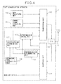
FIG. 4 is a diagram of configuration of a first example of the first communication apparatus. -
FIG. 5 is a diagram of configuration of a first example of a second communication apparatus. -
FIG. 6 is a diagram illustrating a first example of processing carried out in the communication system. -
FIG. 7 is a diagram of configuration of an example of processing carried out in the first communication apparatus. -
FIG. 8 is a diagram of configuration of an example of processing carried out in the second communication apparatus. -
FIG. 9 is a diagram of configuration of a second example of the first communication apparatus. -
FIG. 10 is a diagram of configuration of an example of a synchronization establishment unit of the first communication apparatus. -
FIG. 11 is a diagram of configuration of a second example of the second communication apparatus. -
FIG. 12 is a diagram of configuration of an example of a synchronization establishment unit of the second communication apparatus. -
FIG. 13 is a diagram illustrating a second example of processing carried out in the communication system. -
FIG. 14 is a diagram of configuration of a third example of the first communication apparatus. -
FIG. 15 is a diagram of configuration of a third example of the second communication apparatus. -
FIG. 16 is a diagram illustrating a third example of processing carried out in the communication system. -
FIG. 17 is a diagram illustrating a fourth example of processing carried out in the communication system. - Preferred embodiments will be illustrated below with reference to the attached drawings.
FIG. 1 is a diagram depicting an example of configuration of a communication system. Acommunication system 100 includes afirst communication apparatus 1 and asecond communication apparatus 2. A first link is formed between thefirst communication apparatus 1 and thesecond communication apparatus 2 so that, on the first link, signals are transmitted from thefirst communication apparatus 1 to thesecond communication apparatus 2 by radio communication. Furthermore, a second link is formed between thefirst communication apparatus 1 and thesecond communication apparatus 2 so that, on the second link, signals are transmitted from thesecond communication apparatus 2 to thefirst communication apparatus 1 by radio communication. - For example, the
first communication apparatus 1 and thesecond communication apparatus 2 may be a radio base station apparatus and a radio terminal apparatus, respectively, in a mobile communication system. In this case, the first link is a downlink, i.e., a radio link from the radio base station apparatus to the radio terminal apparatus, and the second link is an uplink, i.e., a radio link from the radio terminal apparatus to the radio base station apparatus. For example, thefirst communication apparatus 1 and thesecond communication apparatus 2 may be a radio terminal apparatus and a radio base station apparatus, respectively. In this case, the first link is an uplink, and the second link is a downlink. However, the description herein is not intended to limit thefirst communication apparatus 1 and thesecond communication apparatus 2 to the radio base station apparatus and the radio terminal apparatus. Thecommunication system 100 disclosed herein is applicable to various communication systems. - The
communication system 100 is designed such that the channel structure of the second link includes at least a synchronous channel and an asynchronous random access channel. On the synchronous channel, thesecond communication apparatus 2 transmits signals to thefirst communication apparatus 1 within the ranges of frequency bands and time frames pre-assigned to thesecond communication apparatus 2. - On the asynchronous random access channel, the
second communication apparatus 2 can transmit signals to thefirst communication apparatus 1 as needed within the ranges of frequency bands and time frames preliminarily secured for the random access channel from the radio resources of the second link. The radio resources for the asynchronous random access channel are separated from the radio resources for the synchronous channel on the second link. This prevents signals on the asynchronous random access channel from conflicting with signals on the synchronous channel. -
FIG. 2 is a diagram depicting an example of the channel structure of the second link. The channel structure of the second link has atime frame 3 with a system bandwidth Bwf. Predetermined frequency bands are assigned toradio resources 4 and 5 of the asynchronous random access channel in a predetermined subframe in aframe 3 repeated at a constant period. In an example depicted inFIG. 2 , frequency bands BW1 and BW2 in the nth subframe are assigned to theradio resources 4 and 5 of the asynchronous random access channel. Furthermore, regions other than theradio resources 4 and 5 are assigned to the synchronous channel. -
FIG. 3 is a diagram illustrating an example of hardware configuration of thefirst communication apparatus 1. The first communication apparatus includes amicroprocessor 10, astorage unit 11, adigital signal processor 12, and abus 13. Furthermore, thefirst communication apparatus 1 includesfrequency conversion units amplification units duplexer 16, and anantenna 17. In the following description and drawings, the microprocessor, the digital signal processor, and the duplexer are sometimes referred to as an "MPU", a "DSP", and a "DUX", respectively. - The
MPU 10, thestorage unit 11, and theDSP 12 are connected together by thebus 13. Thestorage unit 11 stores various programs and data for controlling operation of thefirst communication apparatus 1. Thestorage unit 11 may include a memory, a hard disk, or a nonvolatile memory. - The
MPU 10 carries out processes for controlling the operation of thefirst communication apparatus 1 by executing a program stored in thestorage unit 11. Furthermore, theDSP 12 carries out processes mainly regarding radio communication with thesecond communication apparatus 2 by executing a program stored in thestorage unit 11. Thestorage unit 11 stores the programs executed by theMPU 10 and theDSP 12 and data temporarily used by the programs. - When the
first communication apparatus 1 is a radio base station apparatus, thefirst communication apparatus 1 may include a higher apparatus which controls thefirst communication apparatus 1, a higher node apparatus which connects thefirst communication apparatus 1 to a core network, and a network processor which carries out processes of transmitting and receiving signals to and from other radio base station apparatuses. - The
frequency conversion unit 14 converts a signal generated by theDSP 12 and transmitted from thefirst communication apparatus 1 to thesecond communication apparatus 2, into a radio frequency. Theamplification unit 15 amplifies the radio frequency signal. The amplified signal is transmitted via theDUX 16 and theantenna 17. - The radio signal transmitted by the
second communication apparatus 2 is received at theantenna 17. The received signal is input to theamplification unit 18 via theDUX 16. Theamplification unit 18 amplifies the received signal. Thefrequency conversion unit 19 converts the amplified received signal with the radio frequency into a baseband signal. The baseband signal is processed by theDSP 12. - The
second communication apparatus 2 may also have a configuration similar to a configuration depicted inFIG. 3 . The hardware configuration depicted inFIG. 3 is only an example of a hardware configuration that implements thefirst communication apparatus 1 and thesecond communication apparatus 2. Any other hardware configuration may be adopted provided that the configuration carries out processing described herein. -
FIG. 4 is a diagram of a configuration of a first example of the first communication apparatus. TheMPU 10 andDSP 12 inFIG. 3 carry out information processing using components depicted inFIG. 4 by executing the programs stored in thestorage unit 11. This also applies to other embodiments of thefirst communication apparatus 1.FIG. 4 mainly depicts functions regarding the following description. Thus, thefirst communication apparatus 1 may include components other than the depicted components. - The
first communication apparatus 1 includes adata processing unit 100, a controlinformation processing unit 101, atransmission unit 102, theDUX 16, theantenna 17, and areception unit 104. Thefirst communication apparatus 1 includes asynchronization determination unit 105, an orthogonal-code acquisition unit 106, a success/failure determination unit 107, and aretransmission control unit 108. - The
data processing unit 100 processes data to be transmitted from thefirst communication apparatus 1 to thesecond communication apparatus 2. Thedata processing unit 100 encodes the data and outputs the encoded data. For example, when thefirst communication apparatus 1 is a radio base station apparatus, thefirst communication apparatus 1 may receive data to be transmitted to thesecond communication apparatus 2, from a higher node apparatus, encode the data, and output the encoded data. For example, when thefirst communication apparatus 1 is a radio terminal apparatus, thedata processing unit 100 may generate data to be transmitted to thesecond communication apparatus 2, encode the data, and output the encoded data. - The control
information processing unit 101 generates a control signal to be transmitted to thesecond communication apparatus 2, encodes the control signal in accordance with a predetermined rule, and outputs the encoded control signal. The control signal may be information that allows thesecond communication apparatus 2 to demodulate and decode transmit data transmitted by thefirst communication apparatus 1. Such information may specify a data coding scheme and radio resources for use in data transmission, for example. - The
transmission unit 102 modulates and multiplexes data output by thedata processing unit 100 and control information output by the controlinformation processing unit 101. Thetransmission unit 102 then transmits the modulated and multiplexed data and control information via theDUX 16 and theantenna 17. - A received signal received from the
second communication apparatus 2 via theantenna 17 is input to thereception unit 104 via theDUX 16. Thereception unit 104 demodulates and decodes the received signal from thesecond communication apparatus 2 which are assigned to the respective radio resources in the second link. - A transmit signal from the
second communication apparatus 2 contains an orthogonal code. The transmit signal is transmitted on the asynchronous random access channel in the second link, and may be referred to as a random access signal. The orthogonal code is an example of a pattern for random access. Thesecond communication apparatus 2 determines whether or not a signal received from thefirst communication apparatus 1 via the first link has been successfully decoded. Thesecond communication apparatus 2 modulates the orthogonal signal sequence depending on whether or not decoding has been successful, and transmits the modulated orthogonal signal via the asynchronous random access channel. Thereception unit 104 outputs the orthogonal code received from thesecond communication apparatus 2 to the success/failure determination unit 107. - In the description herein, the data output by the
data processing unit 100 is taken as an example of a signal transmitted from thefirst communication apparatus 1 to thesecond communication apparatus 2 and for which thesecond communication apparatus 2 determines whether or not decoding has been successful. The signal for which thesecond communication apparatus 2 determines whether or not decoding has been successful is sometimes referred to as "transmit data" in order to be distinguished from other signals. However, the description herein is not intended to limit the signal for which thesecond communication apparatus 2 determines whether or not decoding has been successful, to a particular type of signal. - Transmit signals from the
second communication apparatus 2 include reply signals transmitted on the synchronous channel in the second link. The reply signals are an acknowledgement (ACK) signal and a negative acknowledgement (NACK) signal which indicate whether or not the transmit data received from thefirst communication apparatus 1 via the first link has been successfully decoded by thesecond communication apparatus 2. Thereception unit 104 outputs the reply signal received from thesecond communication apparatus 2, to theretransmission control unit 108. - The
synchronization determination unit 105 determines whether or not the synchronization of the synchronous channel on the second link between thefirst communication apparatus 1 and thesecond communication apparatus 2 has been established. For example, thesynchronization determination unit 105 may determine the establishment of synchronization based on whether or not thesecond communication apparatus 2 is continuously transmitting data via the synchronous channel on the second link. However, a method for synchronization determination carried out by thesynchronization determination unit 105 need not be the above-described method. Thesynchronization determination unit 105 may use another method to determine whether or not the synchronization of the synchronous channel has been established. Thesynchronization determination unit 105 outputs the result of the determination to the success/failure determination unit 107. - The orthogonal-
code acquisition unit 106 acquires information on an orthogonal signal sequence which is identical to the orthogonal signal sequence transmitted by thesecond communication apparatus 2 and which have not been modulated by thesecond communication apparatus 2 yet. For example, the orthogonal-code acquisition unit 106 may identify the orthogonal signal sequence in accordance with orthogonal-code specification information shared with thesecond communication apparatus 2. - The orthogonal-code specification information may be, for example, sequence indication information indicating a code sequence corresponding to an orthogonal code. For example, the orthogonal code may be a CAZAC (Constant Amplitude Zero Auto-Correlation) sequence. When the orthogonal code is a CAZAC sequence, the sequence indication information may be, for example, a sequence number and a cyclic shift amount.
- The orthogonal-
code acquisition unit 106 may generate an orthogonal signal sequence in accordance with the orthogonal-code specification information. Furthermore, a plurality of orthogonal signal sequences may be stored in a storage apparatus so that an orthogonal signal sequence specified by the orthogonal-code specification information can be read from the storage apparatus. The orthogonal-code specification information may be the orthogonal code itself. - The orthogonal-
code acquisition unit 106 may transmit the orthogonal-code specification information to thesecond communication apparatus 2 via thetransmission unit 102 so that thesecond communication apparatus 2 can acquire the same code as the orthogonal code acquired by the orthogonal-code acquisition unit 106. The orthogonal-code acquisition unit 106 outputs the acquired orthogonal code to the success/failure determination unit 107. The orthogonal-code specification information is an example of a signal indicating a pattern for random access. Thefirst communication apparatus 1 may transmit the orthogonal-code specification information to thesecond communication apparatus 2 before transmitting data. Thefirst communication apparatus 1 may transmit the orthogonal-code specification information to thesecond communication apparatus 2 while simultaneously transmitting data. - When the synchronization of the synchronous channel on the second link has not been established, the success/
failure determination unit 107 determines whether or not transmit data transmitted from thefirst communication apparatus 1 to thesecond communication apparatus 2 via the first link has been successfully decoded, based on the modulated orthogonal signal sequence in the signal received from thesecond communication apparatus 2 and the non-modulated orthogonal code acquired by the orthogonal-code acquisition unit 106. - For example, the
second communication apparatus 2 may modulate the orthogonal signal sequence by multiplying the orthogonal signal sequence by a code with a value varying depending on whether or not decoding has been successful. Thus, the orthogonal signal sequence transmitted by thesecond communication apparatus 2 is generated based on whether or not decoding has been successful and the orthogonal-code specification information. The success/failure determination unit 107 can determine whether or not the decoding has been successful by multiplying the modulated orthogonal signal sequence by the original orthogonal signal sequence to detect one of two code sequences depending on whether or not decoding has been successful. Thus, the modulated orthogonal signal sequence is used as a reply signal indicating whether or not decoding has been successful. For example, thesecond communication apparatus 2 multiplies the original orthogonal signal sequence by a code bit "1" when decoding has been successful or by a code bit "-1" when decoding has failed. Multiplying the modulated orthogonal signal sequence by the original orthogonal signal sequence results in a multiplied code sequence "1, 1... 1" when decoding has been successful or in a multiplied code sequence "-1, -1... -1" when decoding has failed. - The success/
failure determination unit 107 notifies thetransmission unit 102 of the result of the determination. For example, thetransmission unit 102 may retransmit the data having failed to be decoded, to thesecond communication apparatus 2. - When the synchronization of the synchronous channel on the second link has been established, the
retransmission control unit 108 receives, from thereception unit 104, one of the acknowledgement (ACK) signal and the negative acknowledgement (NACK) signal which has been transmitted by thesecond communication apparatus 2. When the reply signal transmitted by thesecond communication apparatus 2 is the negative acknowledgment (NACK) signal, theretransmission control unit 108 may instruct thetransmission unit 102 to retransmit the data having failed to be decoded, to thesecond communication apparatus 2. - The configuration and functions of the
second communication apparatus 2 will now be illustrated.FIG. 5 is a diagram of configuration of a first example of thesecond communication apparatus 2. TheMPU 10 andDSP 12 inFIG. 3 carry out information processing using components depicted inFIG. 5 by executing the programs stored in thestorage unit 11. This also applies to other embodiments of thesecond communication apparatus 2.FIG. 5 mainly depicts functions regarding the following description. Thus, thesecond communication apparatus 2 may include components other than the depicted components. - The
second communication apparatus 2 includes adata processing unit 200, atransmission unit 201, aDUX 202, anantenna 203, and areception unit 204. Thesecond communication apparatus 2 includes asynchronization determination unit 205, a success/failure determination unit 206, an orthogonal-code acquisition unit 207, amodulation unit 208, aswitch 209, and aretransmission control unit 210. In the attached drawings, the switch is sometimes denoted as "SW". - The
data processing unit 200 processes data to be transmitted from thesecond communication apparatus 2 to thefirst communication apparatus 1. Thedata processing unit 200 encodes the data and outputs the encoded data. For example, when thesecond communication apparatus 2 is a radio terminal apparatus, thedata processing unit 200 may generate data to be transmitted to thefirst communication apparatus 1, encode the data, and output the encoded data. For example, when thesecond communication apparatus 2 is a radio base station apparatus, thesecond communication apparatus 2 may receive data to be transmitted to thefirst communication apparatus 1, from a higher node apparatus, encode the data, and output the encoded data. - The
transmission unit 201 modulates and multiplexes data output by thedata processing unit 200, an orthogonal code selected by theswitch 209, illustrated below, and reply signals output by theretransmission control unit 210, illustrated below. At this time, thetransmission unit 201 assigns the radio resources of the asynchronous random access channel on the second link for the transmission of an orthogonal signal sequence. Thetransmission unit 201 assigns the radio resources of the synchronous channel on the second link for the transmission of reply signals. Thetransmission unit 201 transmits multiplexed signals via theDUX 202 and theantenna 203. - A received signal received from the
first communication apparatus 1 via theantenna 203 is input to thereception unit 204 via theDUX 202. Thereception unit 204 demodulates and decodes the received signals from thefirst communication apparatus 1 which are assigned to the respective radio resources in the first link, in accordance with control information transmitted by thefirst communication apparatus 1. - The success/
failure determination unit 206 determines whether or not thereception unit 204 has successfully decoded the received data from thefirst communication apparatus 1. The success/failure determination unit 206 outputs the result of the determination to theswitch 209 and theretransmission control unit 210. - The
synchronization determination unit 205 determines whether or not the synchronization of the synchronous channel between thefirst communication apparatus 1 and thesecond communication apparatus 2 on the second link has been established. For example, thesynchronization determination unit 205 may determine a loss of synchronization based on whether or not the reception of a signal for correction of transmission timing on the synchronous channel has been stopped, the signal being transmitted by thefirst communication apparatus 1. However, a method for synchronization determination carried out by thesynchronization determination unit 205 need not be the above-described method. Thesynchronization determination unit 205 may use another method to determine whether or not the synchronization of the synchronous channel has been established. Thesynchronization determination unit 205 outputs the result of the determination to themodulation unit 208 and theretransmission control unit 210. - The orthogonal-
code acquisition unit 207 acquires an orthogonal signal sequence to be transmitted to thefirst communication apparatus 1 via the asynchronous random access channel. For example, the orthogonal-code acquisition unit 207 may identify the orthogonal signal sequence in accordance with the orthogonal-code specification information shared with thefirst communication apparatus 1. The orthogonal-code acquisition unit 207 may share the orthogonal-code specification information with thefirst communication apparatus 1 by acquiring the orthogonal-code specification information transmitted by thefirst communication apparatus 1. - The orthogonal-
code acquisition unit 207 may generate an orthogonal signal sequence in accordance with the orthogonal-code specification information. Furthermore, a plurality of orthogonal codes may be stored in a storage apparatus so that an orthogonal code specified by the orthogonal-code specification information can be read from the storage apparatus. Additionally, the orthogonal-code specification information may be the orthogonal code itself. The orthogonal-code acquisition unit 207 outputs the acquired orthogonal signal sequence to themodulation unit 208 and theswitch 209. - The
modulation unit 208 modulates the orthogonal signal sequence, depending on whether or not the transmit data from thefirst communication apparatus 1 has been successfully decoded. For example, themodulation unit 208 may modulate the orthogonal signal sequence by multiplying the original orthogonal signal sequence by a code with a value varying depending on whether or not decoding has been successful. For example, thesecond communication apparatus 2 multiplies the original orthogonal signal sequence by the code bit "1" when decoding has been successful or by the code bit "-1" when decoding has failed. - The
modulation unit 208 outputs the modulated orthogonal signal sequence to theswitch 209. Themodulation unit 208 may be configured so as to modulate the orthogonal signal sequence only when the synchronization of the synchronous channel on the second link has not been established and to avoid modulating the orthogonal signal sequence when the synchronization has been established. - When the synchronization of the synchronous channel on the second link has not been established, the
switch 209 selects the orthogonal signal sequence modulated by themodulation unit 208. When the synchronization of the synchronous channel on the second link has been established, theswitch 209 selects the non-modulated orthogonal signal sequence output by the orthogonal-code acquisition unit 207. Theswitch 209 inputs the selected orthogonal signal sequence to thetransmission unit 201. - The
second communication apparatus 2 may be configured to transmit the orthogonal signal sequence modulated depending on whether or not the transmit data from thefirst communication apparatus 1 has been successfully decoded, regardless of whether or not the synchronization of the synchronous channel on the second link has been established. In this case, theswitch 209 may be omitted. - The
retransmission control unit 210 generates a reply signal depending on whether or not the transmit data from thefirst communication apparatus 1 has been successfully decoded. Theretransmission control unit 210 inputs the reply signal to thetransmission unit 201. - General processing carried out in the
communication system 100 will now be illustrated.FIG. 6 is a diagram illustrating a first example of processing carried out in thecommunication system 100. In other embodiments, operations AA to AF described below may be steps. - In the operation AA, with the synchronization of the synchronous channel on the second link not established yet, an event occurs where the
first communication apparatus 1 transmits transmit data to thesecond communication apparatus 2. For example, thedata processing unit 200 of thefirst communication apparatus 1 acquires, from a higher node, transmit data to be transmitted to thesecond communication apparatus 2. Furthermore, for example, thedata processing unit 200 generates transmit data to be transmitted to thesecond communication apparatus 2. In the operation AB, thetransmission unit 102 of thefirst communication apparatus 1 transmits the transmit data to thesecond communication apparatus 2 via the first channel. - In the operation AC, the
reception unit 204 of thesecond communication apparatus 2 attempts to demodulate and decode the transmit data received via the first channel. The success/failure determination unit 206 determines whether or not the decoding has been successful. In the operation AD, themodulation unit 208 modulates the orthogonal signal sequence depending on whether or not the decoding has been successful. Theswitch 209 inputs the modulated orthogonal signal sequence to thetransmission unit 201. - In the operation AE, the
transmission unit 201 transmits the modulated orthogonal signal sequence to thefirst communication apparatus 1 on the asynchronous random access channel in the second channel. In the operation AF, the success/failure determination unit 107 determines whether or not the transmit data transmitted via the first channel has been successfully decoded based on the received orthogonal signal sequence and the non-modulated orthogonal code. - Processing carried out in each of the
first communication apparatus 1 andsecond communication apparatus 2 in thecommunication system 100 will now be illustrated.FIG. 7 is a diagram illustrating an example of processing carried out in thefirst communication apparatus 1. In other embodiments, operations BA to BG described below may be steps. - In the operation BA, the
synchronization determination unit 105 determines whether or not the synchronization of the synchronous channel on the second link has been established. When the synchronization has been established (operation BA: Y), the processing proceeds to the operation BF. When the synchronization has not been established (operation BA: N), the processing proceeds to the operation BB. - In the operation BB, the
transmission unit 104 transmits the transmit data output by thedata processing unit 100 and the control information received from the controlinformation processing unit 101, to thesecond communication apparatus 2. In the operation BC, thereception unit 104 attempts to receive the orthogonal signal sequence transmitted on the asynchronous random access channel. When the orthogonal signal sequence has been received (operation BC: Y), the processing proceeds to the operation BE. When the orthogonal code has not been received (operation BC: N), the processing proceeds to the operation BD. - In the operation BD, the
retransmission control unit 108 determines whether or not the orthogonal signal sequence has been received within a predetermined time. When the orthogonal signal sequence has not been received within the predetermined time (operation BD: Y), the processing returns to the operation BB. When the predetermined time has not elapsed yet (operation BD: N), the processing proceeds to the operation BC. - In the operation BE, the success/
failure determination unit 107 determines whether or not thesecond communication apparatus 2 has successfully decoded the transmit data transmitted in the operation BB, based on the received orthogonal signal sequence and the non-modulated orthogonal signal sequence acquired by the orthogonal-code acquisition unit 106. When the transmit data has failed to be decoded, thetransmission unit 102 retransmits the same data as the data having failed to be decoded. - In the operation BF, the
transmission unit 104 transmits the transmit data output by thedata processing unit 100 and the control information received from the controlinformation processing unit 101, to thesecond communication apparatus 2. In the operation BG, thereception unit 104 receives the reply signal indicating whether or not the transmit data transmitted via the first channel has been successfully decoded. Theretransmission control unit 210 determines whether or not the reply signal is an acknowledgement signal. When the reply signal is an acknowledgement signal (operation BG: Y), the processing ends. When the reply signal is a negative acknowledgement signal or no reply signal has been successfully received (operation BG: N), the processing returns to the operation BF. -
FIG. 8 is a diagram illustrating an example of processing carried out in thesecond communication apparatus 2. In other embodiments, operations CA to CK described below may be steps. In the operation CA, thereception unit 204 attempts to receive the transmit data and control information transmitted by thefirst communication apparatus 1. - In the operation CB, the
synchronization determination unit 205 determines whether or not the synchronization of the synchronous channel on the second link has been established. When the synchronization has been established (operation CB: Y), the processing proceeds to the operation CH. When the synchronization has not been established (operation CB: N), the processing proceeds to the operation CC. - When the
reception unit 204 has failed to receive the control information (operation CC: N), no processing is carried out on the signal received in the operation CA. In this case, the information on the success or failure of decoding of the transmit data fails to return to thefirst communication apparatus 1, and thus thefirst communication apparatus 1 retransmits the same data. Thus, the processing returns to the operation CA. - When the
reception unit 204 has successfully received the control information (operation CC: Y), the processing proceeds to the operation CD. In the operation CD, the success/failure determination unit 206 determines whether or not the transmit data has been successfully decoded. - In the operation CE, the
modulation unit 208 modulates the orthogonal signal sequence depending on whether or not the decoding has been successful. In the operation CF, thetransmission unit 201 transmits the modulated orthogonal signal sequence to thefirst communication apparatus 1 via the asynchronous random access channel. When the transmit data has been successfully decoded (operation CG: Y), the processing ends. When the transmit data has failed to be decoded (operation CG: N), thefirst communication apparatus 1 retransmits the data. Thus, the processing returns to the operation CA. - In the operation CH, the
reception unit 204 decodes the received transmit data. In the operation CI, the success/failure determination unit 206 determines whether or not the transmit data has been successfully decoded. When the transmit data has been successfully decoded (operation CI: Y), the processing proceeds to the operation CJ. When the transmit data has failed to be decoded (operation CI: N), the processing proceeds to the operation CK. - In the operation CJ, the
retransmission control unit 210 generates an acknowledgement signal. Thetransmission unit 201 transmits the acknowledgement signal to the first communication apparatus via the synchronous channel. Then, the processing ends. In the operation CK, theretransmission control unit 210 generates a negative acknowledgement signal. Thetransmission unit 201 transmits the negative acknowledgement signal to the first communication apparatus via the synchronous channel. Thefirst communication apparatus 1 retransmits the data, and thus, the processing returns to the operation CA. - According to the present embodiment, even when the synchronization of the synchronous channel has not been established, on which the reply signal indicating whether or not the transmit data has been successfully decoded is transmitted, a notification indicating whether or not the transmit data has been successfully decoded can be provided by modulating the orthogonal signal on the asynchronous random access channel. Thus, signals can be transmitted before the process of establishing the synchronization of the synchronous channel is completed. This enables a possible delay in signal transmission to be avoided.
- Radio resources other than the radio resources of the synchronous channel are assigned to the asynchronous random access channel. Thus, the orthogonal signal sequence is prevented from conflicting with other signals transmitted on the synchronous channel. Furthermore, the orthogonal signal sequence avoids interfering with other orthogonal signal sequences flowing on the asynchronous random access channel. Thus, the
second communication apparatus 2 can notify thefirst communication apparatus 1 of the success or failure of decoding without interfering with signals from other communication apparatuses transmitted on the second link. - The orthogonal signal sequence modulated by the
second communication apparatus 2 based on whether or not decoding has been successful may be any orthogonal signal sequence as long as the signal sequence is transmitted through the asynchronous random access channel on the second link. For example, thesecond communication apparatus 2 may modulate a preamble signal used to establish the synchronization of the synchronous channel on the second link, based on whether or not decoding has been successful. - An embodiment of modulation of the preamble signal based on whether or not decoding has been successful will be illustrated below.
FIG. 9 is a diagram of a configuration of a second example of thefirst communication apparatus 1. The same components of the second example as the corresponding components depicted inFIG. 4 are denoted by the same reference numerals. The components denoted by the same reference numerals perform the same operations unless otherwise specified. Furthermore, the components depicted inFIG. 4 and the functions of the components may be provided in other embodiments. - The
first communication apparatus 1 includes aresource management unit 120, ascheduler 121, asynchronization establishment unit 122, and an orthogonal-code generation unit 123. Theresource management unit 120 manages the radio resources of the first link and the second link between thefirst communication apparatus 1 and thesecond communication apparatus 2. - The
resource management unit 120 assigns the radio resources of the second link separately to the synchronous channel and the asynchronous random access channel. Theresource management unit 120 provides information on the current assignment status of the radio resources to thereception unit 104 and thescheduler 121. - Based on the information on the assignment status of the radio resources of the first link provided by the
resource management unit 121, thescheduler 121 identifies radio resources used to transmit the transmit data output by thedata processing unit 100 and the control information output by the controlinformation processing unit 101. Thetransmission unit 102 modulates and multiplexes the transmit data and the control information based on instructions from thescheduler 121. - Furthermore, the
transmission unit 102 multiplexes information on the assignment status of the radio resources of the second link assigned by theresource management unit 120, in transmit signals as control information. Based on the information on the assignment status of the radio resources of the second link, thereception unit 104 demodulates and decodes transmit signals from thesecond communication apparatus 2. - The
synchronization establishment unit 122 carries out a process of establishing the synchronization of the synchronous channel on the second link.FIG. 10 is a diagram of configuration of an example of thesynchronization establishment unit 122 of thefirst communication apparatus 1. Thesynchronization establishment unit 122 includes asequence specification unit 130, a requestsignal generation unit 131, a receptiontime measurement unit 132, and a correctionsignal generation unit 133. - The
sequence specification unit 130 specifies a code sequence of an orthogonal signal sequence for use as a preamble signal in the process of establishing the synchronization of the second link. Thesequence specification unit 130 provides orthogonal-code specification information that specifies a code sequence of an orthogonal signal sequence, to the requestsignal generation unit 131 and the orthogonal-code generation unit 123. - When the
data processing unit 100 notifies the requestsignal generation unit 131 that an event where transmit data is transmitted has occurred, the requestsignal generation unit 131 generates a request signal. The request signal requests thesecond communication apparatus 2 to transmit, via the asynchronous random access channel, the orthogonal signal sequence specified by the orthogonal-code specification information. The requestsignal generation unit 131 transmits the request signal to the second communication apparatus via thetransmission unit 102 as a piece of the above-described control information. - The reception
time measurement unit 132 measures the time of reception of the orthogonal signal sequence transmitted via the asynchronous random access channel and serving as a preamble signal. The correctionsignal generation unit 133 generates a correction signal that corrects timing for the transmission by the second communication apparatus in the synchronous channel on the second link according to the length of time from the time of transmission of the request signal until the time of reception of the orthogonal signal sequence. An example of the correction signal is, for example, TA (Timing Advance) information specified in LTE (Long Term Evolution) that is a communication scheme formulated by 3GPP (The 3rd Generation Partnership Project). The correctionsignal generation unit 133 transmits the correction signal to the second communication apparatus via thetransmission unit 102 as a piece of the above-described control information. The correction signal is an example of timing adjustment information for establishing the synchronization of the synchronous channel on the second link. - Referring to
FIG. 9 , the orthogonal-code generation unit 123 generates the orthogonal signal sequence specified by the orthogonal-code specification information provided by thesequence specification unit 130. The orthogonal-code generation unit 123 outputs the orthogonal signal sequence to the success/failure determination unit 107. - The success/
failure determination unit 107 determines whether or not the transmit data has been successfully decoded based on the modulated orthogonal signal sequence received from thesecond communication apparatus 2 and the non-modulated orthogonal signal sequence acquired by the orthogonal-code generation unit 123. - The configuration of the
second communication apparatus 2 and processing carried out in thesecond communication apparatus 2 will now be illustrated.FIG. 11 is a diagram of configuration of a second example of thesecond communication apparatus 2. The same components of the second example as the corresponding components depicted inFIG. 5 are denoted by the same reference numerals. The components denoted by the same reference numerals perform the same operations unless otherwise specified. Furthermore, the components depicted inFIG. 11 and the functions of the components may be provided in other embodiments. Thesecond communication apparatus 2 includes aresource selection unit 220 and asynchronization establishment unit 221. - The
reception unit 204 receives the information on the assignment status of the radio resources of the second link assigned by theresource management unit 120 of thefirst communication apparatus 1, the request signal requesting transmission of an orthogonal signal sequence as a preamble signal, and the correction signal, from thefirst communication apparatus 1 as control information. - The
resource selection unit 220 manages the radio resources on the second link. Theresource selection unit 220 acquires the information on the assignment status of the radio resources of the second link from thereception unit 204. - Based on the information on the assignment status provided by the
resource selection unit 220, thetransmission unit 201 modulates and multiplexes the data output by thedata processing unit 200, the orthogonal code as a preamble signal, and the reply signal output by theretransmission control unit 210. - The
synchronization establishment unit 221 carries out a process of establishing the synchronization of the synchronous channel on the second link.FIG. 12 is a diagram of configuration of an example of thesynchronization establishment unit 221 of thesecond communication apparatus 2. Thesynchronization establishment unit 221 includes an orthogonal-code generation unit 231 and atiming adjustment unit 232. The orthogonal-code generation unit 231 generates the orthogonal signal sequence specified by the orthogonal-code specification information contained in the request signal. The orthogonal-code generation unit 231 outputs the orthogonal signal sequence to themodulation unit 208 and theswitch 209. - The
timing adjustment unit 232 corrects the timing for the transmission by the second communication apparatus in the synchronous channel on the second link in accordance with the correction signal. Thetiming adjustment unit 232 outputs a corrected transmission timing signal to thetransmission unit 201. Thetransmission unit 201 transmits signals in the synchronous channel on the second link in accordance with the timing signal output by thetiming adjustment unit 232. -
FIG. 13 is a diagram illustrating a second example of processing carried out in thecommunication system 100. In other embodiments, operations DA to DK described below may be steps. In the operation DA, with the synchronization of the synchronous channel on the second link not established yet, an event occurs where thefirst communication apparatus 1 transmits transmit data to thesecond communication apparatus 2. In the operation DB, thetransmission unit 102 of thefirst communication apparatus 1 transmits the transmit data and a request signal requesting thesecond communication apparatus 2 to transmit an orthogonal signal sequence as a preamble signal, to thesecond communication apparatus 2 via the first channel. - In the operation DC, the
reception unit 204 of thesecond communication apparatus 2 attempts to demodulate and decode the transmit data. The success/failure determination unit 206 determines whether or not the decoding has been successful. In the operation DD, the orthogonal-code generation unit 231 generates an orthogonal signal sequence. In the operation DE, themodulation unit 208 modulates the orthogonal signal sequence depending on whether or not the decoding has been successful. In the operation DF, thetransmission unit 201 transmits the modulated orthogonal signal sequence to thefirst communication apparatus 1 on the asynchronous random access channel of the second channel. - In the operation DG, the success/
failure determination unit 107 determines whether or not the transmit data has been successfully decoded, based on the received orthogonal signal sequence and the non-modulated orthogonal signal sequence. In the operation DH, the transmissiontime measurement unit 132 measures the time of reception of the orthogonal signal sequence. - In the operation DI, the correction
signal generation unit 133 generates a correction signal according to the length of time from the time of transmission of the request signal until the time of reception of the orthogonal signal sequence. In the operation DJ, the correctionsignal generation unit 133 transmits the correction signal to thesecond communication apparatus 2 via thetransmission unit 102. In the operation DK, thetiming adjustment unit 232 corrects the transmission timing in the synchronous channel on the second link in accordance with the correction signal. - Either one of the process in the operation DG and each of the processes in the operations DI to DK may be performed before the other.
- According to the present embodiment, when transmit data for the
second communication apparatus 2 is generated while the synchronization of the synchronous channel on the second link is not established, the transmit data can be transmitted when thesecond communication apparatus 2 is simultaneously requested to transmit a preamble signal in order to establish the synchronization. This reduces a possible delay in the transmission of the transmit data. - Furthermore, the present embodiment uses the preamble signal as an orthogonal signal sequence modulated depending on whether or not decoding has been successful. This reduces consumption of the radio resources.
- Another embodiment of the
communication system 100 will now be illustrated. According to the embodiment illustrated below, when transmit data for thesecond communication apparatus 2 is generated while the synchronization of the synchronous channel on the second link is not established, thefirst communication apparatus 1 transmits the transmit data not later than the time of transmission of a correction signal for the timing for the transmission in the synchronous channel on the second link. Then, after the synchronization of the synchronous channel on the second link is established, thefirst communication apparatus 1 receives, via the synchronous channel, a reply signal indicating whether or not the transmit data has been successfully decoded. -
FIG. 14 is a diagram of configuration of a third example of thefirst communication apparatus 1. The same components of the third example as the corresponding components depicted inFIG. 9 are denoted by the same reference numerals. The components denoted by the same reference numerals perform the same operations unless otherwise specified. Furthermore, the components depicted inFIG. 14 and the functions of the components may be provided in other embodiments. - In a certain embodiment, when the synchronization of the synchronous channel on the second link has not been established yet, the
scheduler 121 delays the time of transmission of signals output by thedata processing unit 100 until the time of transmission of the correction signal. - In another embodiment, when the synchronization of the synchronous channel on the second link has not been established yet, the
scheduler 121 transmits transmit data to thesecond communication apparatus 2 earlier than the time of transmission of the correction signal. Theretransmission control unit 108 determines whether or not the transmit data transmitted before the synchronization has been successfully decoded, based on a reply signal received via the synchronous channel after the synchronization. Thus, theretransmission control unit 108 has a retransmission timeout time set therein which is longer than a duration accepted for a synchronization process carried out by thesecond communication apparatus 2. -
FIG. 15 is a diagram of configuration of a third example of thesecond communication apparatus 2. The same components of the third example as the corresponding components depicted inFIG. 11 are denoted by the same reference numerals. The components denoted by the same reference numerals perform the same operations unless otherwise specified. Furthermore, the components depicted inFIG. 15 and the functions of the components may be provided in other embodiments. Thesecond communication apparatus 2 includes astorage unit 222 which stores the result of the determination by the success/failure determination unit 206. - The success/
failure determination unit 206 stores information indicating whether or not data received while the synchronization of the synchronous channel on the second link is not established has been successfully decoded, in thestorage unit 222 until the synchronization is established. Theretransmission control unit 210 transmits a reply signal in accordance with the result of the determination stored in thestorage unit 222 after thesynchronization establishment unit 221 establishes the synchronization of the synchronous channel on the second link. According to the present embodiment, the orthogonal-code generation unit 231 of thesynchronization establishment unit 221 outputs a generated orthogonal signal sequence to thetransmission unit 201. -
FIG. 16 is a diagram illustrating a first example of processing carried out in thecommunication system 100 inFIG. 15 andFIG. 16 . In other embodiments, operations EA to EJ described below may be steps. - In the operation EA, with the synchronization of the synchronous channel on the second link not established yet, an event occurs where the
first communication apparatus 1 transmits transmit data to thesecond communication apparatus 2. In the operation EB, thetransmission unit 102 of thefirst communication apparatus 1 transmits a request signal requesting thesecond communication apparatus 2 to transmit an orthogonal signal sequence as a preamble signal, to thesecond communication apparatus 2 via the first channel. At this time, thetransmission unit 102 causes the operation of transmitting the transmit data to stand by. - In the operation EC, the orthogonal-
code generation unit 231 generates an orthogonal signal sequence. In the operation ED, thetransmission unit 201 transmits the orthogonal code to thefirst communication apparatus 1 on the asynchronous random access channel of the second channel. - In the operation EE, the transmission
time measurement unit 132 measures the time of reception of the orthogonal signal sequence. In the operation EF, the correctionsignal generation unit 133 generates a correction signal according to the length of time from the time of transmission of the request signal until the time of reception of the orthogonal signal sequence. - In the operation EG, the correction
signal generation unit 133 transmits the correction signal to thesecond communication apparatus 2 via thetransmission unit 102. Thetransmission unit 102 transmits transmit data to thesecond communication apparatus 2 simultaneously with the transmission of the correction signal. - In the operation EH, the success/
failure determination unit 206 determines whether or not the transmit data has been successfully decoded. In the operation EI, thetiming adjustment unit 232 corrects the timing for transmission in the synchronous channel on the second link in accordance with the correction signal to establish the synchronization of the synchronous channel. Either one of the operations EH and EI may be performed before the other. In the operation EJ, theretransmission control unit 210 transmits a reply signal indicating whether or not the transmit data has been successfully decoded, to thefirst communication apparatus 1 via the synchronous channel. - According to the present embodiment, the
first communication apparatus 1 can transmit transmit data before the synchronization of the synchronous channel on the second link is established. This reduces a possible delay in the transmission of the transmit data. - A second example of processing carried out in the
communication system 100 inFIG. 15 andFIG. 16 will now be illustrated with reference toFIG. 17 . In other embodiments, operations FA to FJ described below may be steps. - In the operation FA, with the synchronization of the synchronous channel on the second link not established yet, transmit data for the
second communication apparatus 2 is generated. In the operation FB, thetransmission unit 102 transmits the transmit data and a request signal to thesecond communication apparatus 2 via the first channel. - In the operation FC, the success/
failure determination unit 206 determines whether or not the transmit data has been successfully decoded. The result of the determination is stored in thestorage unit 222. In the operation FD, the orthogonal-code generation unit 231 generates an orthogonal code. In the operation FE, thetransmission unit 201 transmits the orthogonal signal sequence to thefirst communication apparatus 1 on the asynchronous random access channel of the second channel. - In the operation FF, the transmission
time measurement unit 132 measures the time of reception of the orthogonal signal sequence. In the operation FG, the correctionsignal generation unit 133 generates a correction signal according to the length of time from the time of transmission of the request signal until the time of reception of the orthogonal signal sequence. In the operation FH, the correctionsignal generation unit 133 transmits the correction signal to thesecond communication apparatus 2 via thetransmission unit 102. - In the operation FI, the
timing adjustment unit 232 corrects the timing for transmission in the synchronous channel on the second link in accordance with the correction signal to establish the synchronization of the synchronous channel. In the operation FJ, theretransmission control unit 210 transmits a reply signal indicating whether or not the transmit data has been successfully decoded, to thefirst communication apparatus 1 via the synchronous channel. - When transmit data for the
second communication apparatus 2 is generated while the synchronization of the synchronous channel on the second link is not established, the transmit data can be transmitted when thesecond communication apparatus 2 is simultaneously requested to transmit a preamble signal in order to establish the synchronization. This reduces a possible delay in the transmission of the transmit data. - All examples and conditional language recited herein are intended for pedagogical purposes to aid the reader in understanding the invention and the concepts contributed by the inventor to furthering the art, and are to be construed as being without limitation to such specifically recited examples and conditions, nor does the organization of such examples in the specification relate to a showing of the superiority and inferiority of the invention. Although the embodiment(s) of the present inventions have been described in detail, it should be understood that the various changes, substitutions, and alterations could be made hereto without departing from the spirit and scope of the invention.
-
- 1
- First communication apparatus
- 2
- Second communication apparatus
- 100
- Communication system
- 102, 201
- Transmission units
- 104
- Reception units
- 105, 205
- Synchronization determination units
- 107, 206
- Success/failure determination unit
- 208
- Modulation unit
- 209
- Switch
Claims (14)
- A method for radio data transmission in a radio communication system including a radio terminal apparatus and a radio base station apparatus, the method comprising:transmitting, by the radio base station apparatus, data and a signal indicating a pattern for random access to an asynchronous radio terminal apparatus not synchronized with the radio base station apparatus on an uplink; andtransmitting, by the asynchronous radio terminal apparatus to the radio base station apparatus via a random access channel, a reply signal generated based on whether or not the data has been correctly received and on a signal received from the radio base station apparatus and indicating the pattern.
- The method for radio data transmission according to claim 1, wherein the radio base station apparatus transmits the signal indicating the pattern for the random access when simultaneously transmitting the data.
- The method for radio data transmission according to claim 2, wherein the radio base station apparatus transmits the signal indicating the pattern for the random access before transmitting the data.
- The method for radio data transmission according to any one of claims 1 to 3, wherein the pattern for the random access is a preamble for use in establishment of synchronization of a synchronous channel.
- The method for radio data transmission according to claim 4, wherein the base station apparatus transmits a request signal requesting transmission of the preamble in conjunction with the transmission of the data, to the asynchronous radio terminal apparatus.
- A method for radio data transmission in a radio communication system including a radio terminal apparatus and a radio base station apparatus, the method comprising:transmitting, by the radio base station apparatus, data to an asynchronous radio terminal apparatus not synchronized with the radio base station apparatus on an uplink, and transmitting timing adjustment information for synchronization simultaneously with or after the transmission of the data; andestablishing a synchronous channel with the radio base station apparatus based on the timing adjustment information and transmitting a reply signal indicating whether or not the data has been correctly received, to the radio base station apparatus via the synchronous channel, by the asynchronous radio terminal apparatus.
- The method for radio data transmission according to claim 6, wherein the radio terminal apparatus stores information indicating whether or not the data has been correctly received, after the data is received and before the synchronization of the synchronous channel is established.
- The method for radio data transmission according to claim 7, wherein the radio base station apparatus carries out a retransmission process of the data depending on whether or not the data has been correctly received, and
a retransmission timeout time for the retransmission process is set to be longer than a time provided for a process of establishing the synchronization of the synchronous channel which process is carried out by the radio terminal apparatus. - A communication system comprising a radio base station apparatus and a radio terminal apparatus,
wherein the radio base station apparatus comprises a transmission unit which transmits data and a signal indicating a pattern for random access to an asynchronous radio terminal apparatus not synchronized with the radio base station apparatus on an uplink, the data and the signal being transmitted by the radio base station apparatus; and
the radio terminal apparatus comprises a transmission unit which transmits, to the radio base station apparatus via a random access channel, a reply signal generated based on whether or not the data has been correctly received and on the signal indicating the pattern which has been received from the radio base station apparatus. - A communication system comprising a radio base station apparatus and a radio terminal apparatus,
wherein the radio base station apparatus comprises a transmission unit which transmits data to an asynchronous radio terminal apparatus not synchronized with the radio base station apparatus on an uplink and which transmits timing adjustment information for synchronization simultaneously with or after the transmission of the data; and
the radio terminal apparatus comprises:a synchronization establishment unit which establishes a synchronous channel with the radio base station apparatus based on the timing adjustment information; anda transmission unit which transmits a reply signal indicating whether or not the data has been correctly received, to the radio base station apparatus via the synchronous channel. - A radio terminal apparatus comprising:a reception unit which receives data and a signal indicating a pattern for random access, the data and the signal being transmitted from a radio base station apparatus to a radio terminal apparatus not synchronized with the radio base station apparatus on an uplink; anda transmission unit which transmits, to the radio base station apparatus via a random access channel, a reply signal generated based on whether or not the data has been correctly received and on the signal indicating the pattern which has been received from the radio base station apparatus.
- A radio base station apparatus comprising:a transmission unit which transmits data and a signal indicating a pattern for random access to an asynchronous radio terminal apparatus which is a radio terminal apparatus not synchronized with the radio base station apparatus on an uplink; anda reception unit which receives, via a random access channel, a reply signal generated based on whether or not the data has been correctly received and on the signal indicating the pattern.
- A radio base station apparatus comprising:a transmission unit which transmits data to an asynchronous radio terminal apparatus which is a radio terminal apparatus not synchronized with the radio base station apparatus on an uplink and which transmits timing adjustment information for synchronization simultaneously with or after the transmission of the data; anda reception unit which receives a reply signal indicating whether or not the data has been correctly received, from the radio terminal apparatus (2) via the synchronous channel.
- A radio terminal apparatus comprising:a reception unit which receives data transmitted from a radio base station apparatus to the radio terminal apparatus not synchronized with the radio base station apparatus on an uplink and timing adjustment information for synchronization transmitted by the radio base station apparatus simultaneously with or after the transmission of the data;a synchronization establishment unit which establishes a synchronous channel with the radio base station apparatus based on the timing adjustment information; anda transmission unit which transmits a reply signal indicating whether or not the data has been correctly received, to the radio base station apparatus via the synchronous channel.
Applications Claiming Priority (1)
| Application Number | Priority Date | Filing Date | Title |
|---|---|---|---|
| PCT/JP2011/052916 WO2012108045A1 (en) | 2011-02-10 | 2011-02-10 | Wireless data transmission method, communication system, wireless terminal device and wireless base station device |
Publications (3)
| Publication Number | Publication Date |
|---|---|
| EP2675209A1 true EP2675209A1 (en) | 2013-12-18 |
| EP2675209A4 EP2675209A4 (en) | 2017-05-24 |
| EP2675209B1 EP2675209B1 (en) | 2020-04-22 |
Family
ID=46638284
Family Applications (1)
| Application Number | Title | Priority Date | Filing Date |
|---|---|---|---|
| EP11858261.8A Active EP2675209B1 (en) | 2011-02-10 | 2011-02-10 | Wireless data transmission method, communication system, wireless terminal device and wireless base station device |
Country Status (6)
| Country | Link |
|---|---|
| US (1) | US20130294388A1 (en) |
| EP (1) | EP2675209B1 (en) |
| JP (1) | JP5629333B2 (en) |
| KR (2) | KR101524995B1 (en) |
| CN (1) | CN103348725B (en) |
| WO (1) | WO2012108045A1 (en) |
Families Citing this family (6)
| Publication number | Priority date | Publication date | Assignee | Title |
|---|---|---|---|---|
| CN103260251B (en) * | 2012-02-17 | 2016-06-15 | 华为技术有限公司 | Data transmission method, base station and subscriber equipment |
| US9854506B2 (en) * | 2013-08-08 | 2017-12-26 | Qualcomm Incorporated | Timing synchronization for device-to-device discovery for asynchronous LTE deployments |
| CN104640195B (en) * | 2013-11-13 | 2018-03-30 | 普天信息技术研究院有限公司 | A kind of method for transmitting data |
| US10652844B1 (en) * | 2014-01-07 | 2020-05-12 | Marvell Asia Pte. Ltd. | Paging auto-acknowledgement |
| WO2015142664A1 (en) * | 2014-03-20 | 2015-09-24 | Interdigital Patent Holdings, Inc. | Method and apparatus for non-orthogonal access in lte systems |
| CN109565484B (en) * | 2016-08-10 | 2021-02-09 | 华为技术有限公司 | Common synchronization signal for new wireless carriers supporting different subcarrier spacings |
Family Cites Families (11)
| Publication number | Priority date | Publication date | Assignee | Title |
|---|---|---|---|---|
| US7401465B2 (en) | 2005-11-16 | 2008-07-22 | Deere & Company | Dual pump dual pressure hydraulic circuit |
| CN102882589A (en) | 2006-05-05 | 2013-01-16 | 北京新岸线移动通信技术有限公司 | Radio link failure detection procedures in long term evolution uplink and downlink and apparatus therefor |
| JP4603075B2 (en) * | 2006-06-19 | 2010-12-22 | 株式会社エヌ・ティ・ティ・ドコモ | Base station, mobile station, synchronization control method, and IC chip |
| GB2441165B (en) * | 2006-08-21 | 2011-02-09 | Ipwireless Inc | Cellular communication system, network controller and method for obtaining feedback from subscriber communication units |
| KR101319872B1 (en) * | 2006-10-04 | 2013-10-29 | 엘지전자 주식회사 | Method For Transmitting Control Signal, And Method For Allocating Communication Resource To Do The Same |
| JP2008155935A (en) | 2006-12-22 | 2008-07-10 | Kao Corp | Packaging bag |
| JP5137265B2 (en) * | 2007-03-13 | 2013-02-06 | シャープ株式会社 | Mobile communication system, mobile station apparatus, base station apparatus, and mobile communication method |
| JP5140300B2 (en) * | 2007-03-23 | 2013-02-06 | 株式会社エヌ・ティ・ティ・ドコモ | Mobile station, radio base station, and synchronization establishment method |
| PT2661133T (en) * | 2007-08-08 | 2016-08-23 | Huawei Tech Co Ltd | Timing alignment in a radio communication system |
| JP5169442B2 (en) * | 2008-04-25 | 2013-03-27 | 富士通株式会社 | Radio base station, mobile station, and communication method |
| KR101549022B1 (en) * | 2008-11-03 | 2015-09-01 | 엘지전자 주식회사 | A random access method of a user equipment to a base station in a wireless communiaction system supproting uplink and downlink multi carriers |
-
2011
- 2011-02-10 EP EP11858261.8A patent/EP2675209B1/en active Active
- 2011-02-10 WO PCT/JP2011/052916 patent/WO2012108045A1/en active Application Filing
- 2011-02-10 CN CN201180067119.5A patent/CN103348725B/en active Active
- 2011-02-10 JP JP2012556721A patent/JP5629333B2/en active Active
- 2011-02-10 KR KR1020157008977A patent/KR101524995B1/en active IP Right Grant
- 2011-02-10 KR KR1020137020642A patent/KR101514590B1/en active IP Right Grant
-
2013
- 2013-07-11 US US13/940,030 patent/US20130294388A1/en not_active Abandoned
Non-Patent Citations (1)
| Title |
|---|
| See references of WO2012108045A1 * |
Also Published As
| Publication number | Publication date |
|---|---|
| JPWO2012108045A1 (en) | 2014-07-03 |
| CN103348725A (en) | 2013-10-09 |
| KR20130121149A (en) | 2013-11-05 |
| US20130294388A1 (en) | 2013-11-07 |
| KR101514590B1 (en) | 2015-04-22 |
| JP5629333B2 (en) | 2014-11-19 |
| KR101524995B1 (en) | 2015-06-01 |
| KR20150046357A (en) | 2015-04-29 |
| EP2675209A4 (en) | 2017-05-24 |
| EP2675209B1 (en) | 2020-04-22 |
| CN103348725B (en) | 2017-05-03 |
| WO2012108045A1 (en) | 2012-08-16 |
Similar Documents
| Publication | Publication Date | Title |
|---|---|---|
| EP3518605A1 (en) | Random access method, device, and equipment | |
| AU2008301677C1 (en) | Radio communication system, base station device, mobile station device, and random access method | |
| US9369257B2 (en) | Base station, mobile station, control method, and communication system | |
| CN109076602B (en) | Radio network node, wireless device and methods performed therein | |
| EP2675209B1 (en) | Wireless data transmission method, communication system, wireless terminal device and wireless base station device | |
| US20160255654A1 (en) | Uplink Contention Based Multiple Access for Cellular IoT | |
| CN109314674B (en) | Delaying transmission depending on transmission type and UE processing capability | |
| US10652899B2 (en) | Data transmission method and apparatus | |
| EP3384622B1 (en) | Ack/nack messaging in a single frequency network | |
| JP7394835B2 (en) | Terminals, communication methods and integrated circuits | |
| KR20140015534A (en) | Mobile station device, base station device, communication system, and communication method | |
| US20190053208A1 (en) | Information transmission method and system, and device | |
| CN112970237A (en) | Resource allocation for feedback in multicast communications | |
| US11330631B2 (en) | Remote apparatus in base station, base station, and random access method | |
| JP5450333B2 (en) | Initial access setting information generating apparatus, initial access setting information generating method, initial access setting information generating program, and base station apparatus | |
| CN110267352B (en) | User terminal scheduling method and device | |
| CN114208361A (en) | Method, apparatus and computer readable medium for contention window adjustment | |
| US10945162B2 (en) | Special uplink subframe for enhanced mobility | |
| US20220104279A1 (en) | Terminal and communication method | |
| EP3637646A1 (en) | Information transmitting and receiving method, device, equipment and storage medium | |
| RU2788630C1 (en) | Terminal and transmission method | |
| WO2022236534A1 (en) | Hybrid automatic repeat request acknowledgement codebook generation techniques | |
| CN115134896A (en) | Power saving method for monitoring data channel | |
| EP2675211A1 (en) | Response method, communication system and communication device | |
| KR20170001557A (en) | Method and apparatus for en bloc and incrementally transmitting signal |
Legal Events
| Date | Code | Title | Description |
|---|---|---|---|
| PUAI | Public reference made under article 153(3) epc to a published international application that has entered the european phase |
Free format text: ORIGINAL CODE: 0009012 |
|
| 17P | Request for examination filed |
Effective date: 20130904 |
|
| AK | Designated contracting states |
Kind code of ref document: A1 Designated state(s): AL AT BE BG CH CY CZ DE DK EE ES FI FR GB GR HR HU IE IS IT LI LT LU LV MC MK MT NL NO PL PT RO RS SE SI SK SM TR |
|
| DAX | Request for extension of the european patent (deleted) | ||
| RIC1 | Information provided on ipc code assigned before grant |
Ipc: H04W 28/04 20090101AFI20170116BHEP Ipc: H04W 74/08 20090101ALI20170116BHEP |
|
| RA4 | Supplementary search report drawn up and despatched (corrected) |
Effective date: 20170426 |
|
| RIC1 | Information provided on ipc code assigned before grant |
Ipc: H04W 74/08 20090101ALI20170420BHEP Ipc: H04W 28/04 20090101AFI20170420BHEP |
|
| STAA | Information on the status of an ep patent application or granted ep patent |
Free format text: STATUS: EXAMINATION IS IN PROGRESS |
|
| 17Q | First examination report despatched |
Effective date: 20180228 |
|
| GRAP | Despatch of communication of intention to grant a patent |
Free format text: ORIGINAL CODE: EPIDOSNIGR1 |
|
| STAA | Information on the status of an ep patent application or granted ep patent |
Free format text: STATUS: GRANT OF PATENT IS INTENDED |
|
| INTG | Intention to grant announced |
Effective date: 20191204 |
|
| GRAS | Grant fee paid |
Free format text: ORIGINAL CODE: EPIDOSNIGR3 |
|
| GRAA | (expected) grant |
Free format text: ORIGINAL CODE: 0009210 |
|
| STAA | Information on the status of an ep patent application or granted ep patent |
Free format text: STATUS: THE PATENT HAS BEEN GRANTED |
|
| AK | Designated contracting states |
Kind code of ref document: B1 Designated state(s): AL AT BE BG CH CY CZ DE DK EE ES FI FR GB GR HR HU IE IS IT LI LT LU LV MC MK MT NL NO PL PT RO RS SE SI SK SM TR |
|
| REG | Reference to a national code |
Ref country code: GB Ref legal event code: FG4D |
|
| REG | Reference to a national code |
Ref country code: CH Ref legal event code: EP |
|
| REG | Reference to a national code |
Ref country code: IE Ref legal event code: FG4D |
|
| REG | Reference to a national code |
Ref country code: DE Ref legal event code: R096 Ref document number: 602011066452 Country of ref document: DE |
|
| REG | Reference to a national code |
Ref country code: AT Ref legal event code: REF Ref document number: 1261798 Country of ref document: AT Kind code of ref document: T Effective date: 20200515 |
|
| REG | Reference to a national code |
Ref country code: LT Ref legal event code: MG4D |
|
| REG | Reference to a national code |
Ref country code: NL Ref legal event code: MP Effective date: 20200422 |
|
| PG25 | Lapsed in a contracting state [announced via postgrant information from national office to epo] |
Ref country code: SE Free format text: LAPSE BECAUSE OF FAILURE TO SUBMIT A TRANSLATION OF THE DESCRIPTION OR TO PAY THE FEE WITHIN THE PRESCRIBED TIME-LIMIT Effective date: 20200422 Ref country code: NL Free format text: LAPSE BECAUSE OF FAILURE TO SUBMIT A TRANSLATION OF THE DESCRIPTION OR TO PAY THE FEE WITHIN THE PRESCRIBED TIME-LIMIT Effective date: 20200422 Ref country code: LT Free format text: LAPSE BECAUSE OF FAILURE TO SUBMIT A TRANSLATION OF THE DESCRIPTION OR TO PAY THE FEE WITHIN THE PRESCRIBED TIME-LIMIT Effective date: 20200422 Ref country code: PT Free format text: LAPSE BECAUSE OF FAILURE TO SUBMIT A TRANSLATION OF THE DESCRIPTION OR TO PAY THE FEE WITHIN THE PRESCRIBED TIME-LIMIT Effective date: 20200824 Ref country code: IS Free format text: LAPSE BECAUSE OF FAILURE TO SUBMIT A TRANSLATION OF THE DESCRIPTION OR TO PAY THE FEE WITHIN THE PRESCRIBED TIME-LIMIT Effective date: 20200822 Ref country code: GR Free format text: LAPSE BECAUSE OF FAILURE TO SUBMIT A TRANSLATION OF THE DESCRIPTION OR TO PAY THE FEE WITHIN THE PRESCRIBED TIME-LIMIT Effective date: 20200723 Ref country code: NO Free format text: LAPSE BECAUSE OF FAILURE TO SUBMIT A TRANSLATION OF THE DESCRIPTION OR TO PAY THE FEE WITHIN THE PRESCRIBED TIME-LIMIT Effective date: 20200722 Ref country code: FI Free format text: LAPSE BECAUSE OF FAILURE TO SUBMIT A TRANSLATION OF THE DESCRIPTION OR TO PAY THE FEE WITHIN THE PRESCRIBED TIME-LIMIT Effective date: 20200422 |
|
| REG | Reference to a national code |
Ref country code: AT Ref legal event code: MK05 Ref document number: 1261798 Country of ref document: AT Kind code of ref document: T Effective date: 20200422 |
|
| PG25 | Lapsed in a contracting state [announced via postgrant information from national office to epo] |
Ref country code: BG Free format text: LAPSE BECAUSE OF FAILURE TO SUBMIT A TRANSLATION OF THE DESCRIPTION OR TO PAY THE FEE WITHIN THE PRESCRIBED TIME-LIMIT Effective date: 20200722 Ref country code: RS Free format text: LAPSE BECAUSE OF FAILURE TO SUBMIT A TRANSLATION OF THE DESCRIPTION OR TO PAY THE FEE WITHIN THE PRESCRIBED TIME-LIMIT Effective date: 20200422 Ref country code: LV Free format text: LAPSE BECAUSE OF FAILURE TO SUBMIT A TRANSLATION OF THE DESCRIPTION OR TO PAY THE FEE WITHIN THE PRESCRIBED TIME-LIMIT Effective date: 20200422 Ref country code: HR Free format text: LAPSE BECAUSE OF FAILURE TO SUBMIT A TRANSLATION OF THE DESCRIPTION OR TO PAY THE FEE WITHIN THE PRESCRIBED TIME-LIMIT Effective date: 20200422 |
|
| PG25 | Lapsed in a contracting state [announced via postgrant information from national office to epo] |
Ref country code: AL Free format text: LAPSE BECAUSE OF FAILURE TO SUBMIT A TRANSLATION OF THE DESCRIPTION OR TO PAY THE FEE WITHIN THE PRESCRIBED TIME-LIMIT Effective date: 20200422 |
|
| REG | Reference to a national code |
Ref country code: DE Ref legal event code: R082 Ref document number: 602011066452 Country of ref document: DE Representative=s name: HL KEMPNER PATENTANWAELTE, SOLICITORS (ENGLAND, DE Ref country code: DE Ref legal event code: R082 Ref document number: 602011066452 Country of ref document: DE Representative=s name: HL KEMPNER PATENTANWALT, RECHTSANWALT, SOLICIT, DE |
|
| REG | Reference to a national code |
Ref country code: DE Ref legal event code: R097 Ref document number: 602011066452 Country of ref document: DE |
|
| PG25 | Lapsed in a contracting state [announced via postgrant information from national office to epo] |
Ref country code: SM Free format text: LAPSE BECAUSE OF FAILURE TO SUBMIT A TRANSLATION OF THE DESCRIPTION OR TO PAY THE FEE WITHIN THE PRESCRIBED TIME-LIMIT Effective date: 20200422 Ref country code: IT Free format text: LAPSE BECAUSE OF FAILURE TO SUBMIT A TRANSLATION OF THE DESCRIPTION OR TO PAY THE FEE WITHIN THE PRESCRIBED TIME-LIMIT Effective date: 20200422 Ref country code: AT Free format text: LAPSE BECAUSE OF FAILURE TO SUBMIT A TRANSLATION OF THE DESCRIPTION OR TO PAY THE FEE WITHIN THE PRESCRIBED TIME-LIMIT Effective date: 20200422 Ref country code: DK Free format text: LAPSE BECAUSE OF FAILURE TO SUBMIT A TRANSLATION OF THE DESCRIPTION OR TO PAY THE FEE WITHIN THE PRESCRIBED TIME-LIMIT Effective date: 20200422 Ref country code: EE Free format text: LAPSE BECAUSE OF FAILURE TO SUBMIT A TRANSLATION OF THE DESCRIPTION OR TO PAY THE FEE WITHIN THE PRESCRIBED TIME-LIMIT Effective date: 20200422 Ref country code: RO Free format text: LAPSE BECAUSE OF FAILURE TO SUBMIT A TRANSLATION OF THE DESCRIPTION OR TO PAY THE FEE WITHIN THE PRESCRIBED TIME-LIMIT Effective date: 20200422 Ref country code: CZ Free format text: LAPSE BECAUSE OF FAILURE TO SUBMIT A TRANSLATION OF THE DESCRIPTION OR TO PAY THE FEE WITHIN THE PRESCRIBED TIME-LIMIT Effective date: 20200422 Ref country code: ES Free format text: LAPSE BECAUSE OF FAILURE TO SUBMIT A TRANSLATION OF THE DESCRIPTION OR TO PAY THE FEE WITHIN THE PRESCRIBED TIME-LIMIT Effective date: 20200422 |
|
| PG25 | Lapsed in a contracting state [announced via postgrant information from national office to epo] |
Ref country code: PL Free format text: LAPSE BECAUSE OF FAILURE TO SUBMIT A TRANSLATION OF THE DESCRIPTION OR TO PAY THE FEE WITHIN THE PRESCRIBED TIME-LIMIT Effective date: 20200422 Ref country code: SK Free format text: LAPSE BECAUSE OF FAILURE TO SUBMIT A TRANSLATION OF THE DESCRIPTION OR TO PAY THE FEE WITHIN THE PRESCRIBED TIME-LIMIT Effective date: 20200422 |
|
| PLBE | No opposition filed within time limit |
Free format text: ORIGINAL CODE: 0009261 |
|
| STAA | Information on the status of an ep patent application or granted ep patent |
Free format text: STATUS: NO OPPOSITION FILED WITHIN TIME LIMIT |
|
| 26N | No opposition filed |
Effective date: 20210125 |
|
| PG25 | Lapsed in a contracting state [announced via postgrant information from national office to epo] |
Ref country code: SI Free format text: LAPSE BECAUSE OF FAILURE TO SUBMIT A TRANSLATION OF THE DESCRIPTION OR TO PAY THE FEE WITHIN THE PRESCRIBED TIME-LIMIT Effective date: 20200422 |
|
| PG25 | Lapsed in a contracting state [announced via postgrant information from national office to epo] |
Ref country code: MC Free format text: LAPSE BECAUSE OF FAILURE TO SUBMIT A TRANSLATION OF THE DESCRIPTION OR TO PAY THE FEE WITHIN THE PRESCRIBED TIME-LIMIT Effective date: 20200422 |
|
| REG | Reference to a national code |
Ref country code: BE Ref legal event code: MM Effective date: 20210228 |
|
| PG25 | Lapsed in a contracting state [announced via postgrant information from national office to epo] |
Ref country code: CH Free format text: LAPSE BECAUSE OF NON-PAYMENT OF DUE FEES Effective date: 20210228 Ref country code: LI Free format text: LAPSE BECAUSE OF NON-PAYMENT OF DUE FEES Effective date: 20210228 Ref country code: LU Free format text: LAPSE BECAUSE OF NON-PAYMENT OF DUE FEES Effective date: 20210210 |
|
| PG25 | Lapsed in a contracting state [announced via postgrant information from national office to epo] |
Ref country code: IE Free format text: LAPSE BECAUSE OF NON-PAYMENT OF DUE FEES Effective date: 20210210 |
|
| PGFP | Annual fee paid to national office [announced via postgrant information from national office to epo] |
Ref country code: FR Payment date: 20220118 Year of fee payment: 12 |
|
| PG25 | Lapsed in a contracting state [announced via postgrant information from national office to epo] |
Ref country code: BE Free format text: LAPSE BECAUSE OF NON-PAYMENT OF DUE FEES Effective date: 20210228 |
|
| PGFP | Annual fee paid to national office [announced via postgrant information from national office to epo] |
Ref country code: GB Payment date: 20221230 Year of fee payment: 13 |
|
| PG25 | Lapsed in a contracting state [announced via postgrant information from national office to epo] |
Ref country code: HU Free format text: LAPSE BECAUSE OF FAILURE TO SUBMIT A TRANSLATION OF THE DESCRIPTION OR TO PAY THE FEE WITHIN THE PRESCRIBED TIME-LIMIT; INVALID AB INITIO Effective date: 20110210 Ref country code: CY Free format text: LAPSE BECAUSE OF FAILURE TO SUBMIT A TRANSLATION OF THE DESCRIPTION OR TO PAY THE FEE WITHIN THE PRESCRIBED TIME-LIMIT Effective date: 20200422 |
|
| PGFP | Annual fee paid to national office [announced via postgrant information from national office to epo] |
Ref country code: DE Payment date: 20221229 Year of fee payment: 13 |