EP2674832A2 - Portable electronic device - Google Patents
Portable electronic device Download PDFInfo
- Publication number
- EP2674832A2 EP2674832A2 EP13150657.8A EP13150657A EP2674832A2 EP 2674832 A2 EP2674832 A2 EP 2674832A2 EP 13150657 A EP13150657 A EP 13150657A EP 2674832 A2 EP2674832 A2 EP 2674832A2
- Authority
- EP
- European Patent Office
- Prior art keywords
- assembling
- electronic device
- portable electronic
- assembling unit
- electronic module
- Prior art date
- Legal status (The legal status is an assumption and is not a legal conclusion. Google has not performed a legal analysis and makes no representation as to the accuracy of the status listed.)
- Withdrawn
Links
Images




Classifications
-
- H—ELECTRICITY
- H05—ELECTRIC TECHNIQUES NOT OTHERWISE PROVIDED FOR
- H05K—PRINTED CIRCUITS; CASINGS OR CONSTRUCTIONAL DETAILS OF ELECTRIC APPARATUS; MANUFACTURE OF ASSEMBLAGES OF ELECTRICAL COMPONENTS
- H05K7/00—Constructional details common to different types of electric apparatus
- H05K7/02—Arrangements of circuit components or wiring on supporting structure
- H05K7/026—Multiple connections subassemblies
-
- G—PHYSICS
- G06—COMPUTING OR CALCULATING; COUNTING
- G06F—ELECTRIC DIGITAL DATA PROCESSING
- G06F1/00—Details not covered by groups G06F3/00 - G06F13/00 and G06F21/00
- G06F1/16—Constructional details or arrangements
- G06F1/1613—Constructional details or arrangements for portable computers
- G06F1/1615—Constructional details or arrangements for portable computers with several enclosures having relative motions, each enclosure supporting at least one I/O or computing function
-
- G—PHYSICS
- G06—COMPUTING OR CALCULATING; COUNTING
- G06F—ELECTRIC DIGITAL DATA PROCESSING
- G06F1/00—Details not covered by groups G06F3/00 - G06F13/00 and G06F21/00
- G06F1/16—Constructional details or arrangements
- G06F1/1613—Constructional details or arrangements for portable computers
- G06F1/1633—Constructional details or arrangements of portable computers not specific to the type of enclosures covered by groups G06F1/1615 - G06F1/1626
- G06F1/1637—Details related to the display arrangement, including those related to the mounting of the display in the housing
- G06F1/1654—Details related to the display arrangement, including those related to the mounting of the display in the housing the display being detachable, e.g. for remote use
-
- G—PHYSICS
- G06—COMPUTING OR CALCULATING; COUNTING
- G06F—ELECTRIC DIGITAL DATA PROCESSING
- G06F1/00—Details not covered by groups G06F3/00 - G06F13/00 and G06F21/00
- G06F1/16—Constructional details or arrangements
- G06F1/1613—Constructional details or arrangements for portable computers
- G06F1/1633—Constructional details or arrangements of portable computers not specific to the type of enclosures covered by groups G06F1/1615 - G06F1/1626
- G06F1/1662—Details related to the integrated keyboard
- G06F1/1669—Detachable keyboards
-
- G—PHYSICS
- G06—COMPUTING OR CALCULATING; COUNTING
- G06F—ELECTRIC DIGITAL DATA PROCESSING
- G06F1/00—Details not covered by groups G06F3/00 - G06F13/00 and G06F21/00
- G06F1/16—Constructional details or arrangements
- G06F1/1613—Constructional details or arrangements for portable computers
- G06F1/1633—Constructional details or arrangements of portable computers not specific to the type of enclosures covered by groups G06F1/1615 - G06F1/1626
- G06F1/1675—Miscellaneous details related to the relative movement between the different enclosures or enclosure parts
- G06F1/1683—Miscellaneous details related to the relative movement between the different enclosures or enclosure parts for the transmission of signal or power between the different housings, e.g. details of wired or wireless communication, passage of cabling
-
- H—ELECTRICITY
- H05—ELECTRIC TECHNIQUES NOT OTHERWISE PROVIDED FOR
- H05K—PRINTED CIRCUITS; CASINGS OR CONSTRUCTIONAL DETAILS OF ELECTRIC APPARATUS; MANUFACTURE OF ASSEMBLAGES OF ELECTRICAL COMPONENTS
- H05K7/00—Constructional details common to different types of electric apparatus
Definitions
- the present invention relates to a portable electronic device and more particularly, to a portable electronic device which the bodies thereof are separable.
- the volume of the device is rather limited.
- the devices such as mobile phones or tablet PC
- a screen and a keypad are both disposed on the device
- the size of the screen has to be reduced.
- a touch screen has been developed recently.
- the touch screen displays the corresponding operation interfaces according to the execution demand of each application for a user to operate the functions of the applications by touching. For example, when the user activates a document editing program, a virtual keypad is displayed on the touch screen for the user to input characters.
- control keys such as display key, pause key, stop key, forward key, rewind key, etc., are displayed on the touch screen for the user to operate the functions of the media player program.
- the interfaces such as key pad, control keys, etc., displayed on the touch screen still occupy considerable display space of the screen, other contents are thus compressed which is harder for the user to read.
- the touch screen is turned off to keep the user from touching the touch screen accidentally, so the user can not perform operations on the portable electronic device.
- the present invention provides a portable electronic device which the bodies thereof are separable so as to have more flexible operation status and greater operation range.
- a portable electronic device including a first body, a second body and an assembling structure.
- the assembling structure includes a first assembling unit and a second assembling unit, wherein the first assembling unit is adapted to hidden in one of the first body and the second body.
- the first assembling unit is protruded out of the first body or the second body, and is correspondingly assembled to the second assembling unit, such that the first body and the second body are fixed together.
- the first body and the second body of the portable electronic device are separable so as to provide the portable electronic device greater and more flexible operation environment.
- the assembling structure includes the first assembling unit and the second assembling unit respectively disposed in the first body and the second body, so that when close to each other, the first body and the second body can be fixed together by the assembling units assembled to each other.
- FIG. 1 is a schematic view of a portable electronic device according to an embodiment of the present invention.
- FIG. 2 is a schematic view of the portable electronic device in Fig. 1 under another operation status.
- FIG. 3 is a usage scenario of the portable electronic device under the status of FIG. 2 .
- FIG. 4 and FIG. 5 are schematic views respectively illustrating the statuses of the portable electronic device in FIG. 2 after assembled.
- FIG. 6 is a schematic view of a portable electronic device according to another embodiment of the present invention.
- FIG. 7 is a schematic view of a portable electronic device after assembled according to an embodiment of the present invention.
- FIG. 8 is a schematic view of a portable electronic device after assembled according to another embodiment of the present invention.
- FIG. 9 is a schematic view of a portable electronic device after assembled according to another embodiment of the present invention.
- FIG. 1 is a schematic view of a portable electronic device according to an embodiment of the present invention.
- Fig. 2 is a schematic view of the portable electronic device in Fig. 1 under another operation status.
- FIG. 3 is a usage scenario of the portable electronic device under the status of FIG. 2 .
- the portable electronic device 100 includes a first body 110 and a second body 120, which achieve the stacked status shown in FIG. 1 by the magnetic assembling elements 130A, 130B respectively disposed therein.
- the separated status shown in FIG. 2 are achieved.
- wireless transmission modules can further be respectively disposed on the first body 110 and the second body 120 of the portable electronic device 100 so that the first body 110 and the second body 120 can still be able to proceed data transmission when the first body 110 and the second body 120 are separated from each other.
- the first body 110 and the second body 120 respectively have a first display surface 112 and a second display surface 122, which respectively are touch screens. Then, the images displayed on the first display surface 112 and the second display surface 122 are varied according to a connecting condition between the first body 110 and the second body 120 and types of applications being executed.
- the portable electronic device 100 when the first body 110 and the second body 120 of the portable electronic device 100 are stacked together, the portable electronic device 100 is operated as a mobile phone for a user to dial and answer phone calls or sending and receiving messages.
- the portable electronic device 100 when the user uses the portable electronic device 100 to answer a phone call, if the user needs to search some data such as phone numbers of other contacts or the location of the user himself, etc., the second body 120 can be removed from the first body 110, as shown in FIG. 3 , such that the user can answer the phone call by the first body 110 and search the needed data by operating the second body 120 at the same time.
- the search result can be transmitted back to the first body 110 from the second body 120 through the wireless connection between the first body 110 and the second body 120, so as to be transmitted to a user at the other side of the phone through the communicating connection of the first body 110.
- the second body 120 of the present embodiment further has a photography module (not shown) at the back of the second display surface 122.
- a photography module (not shown) at the back of the second display surface 122.
- the second body 120 can be removed from the first body 110, such that the user can answer the phone call by the first body 110 and take photos by operating the second body 120 at the same time, and images taken by the second body 120 can be transmitted back to the first body 110 through the wireless connection between the first body 110 and the second body 120, so the images can be transmitted to a user at the other side of the phone through communicating connection of the first body 110.
- the present invention does not limit the types of the portable electronic device 100.
- the above-mentioned first body 110 and the second body 120 can be a thin electronic device such as mobile phone, personal digital assistant (PDA) or tablet PC, etc.
- the first body 110 and the second body 120 can be operated independently and also can be stacked and operated as a single device.
- FIG. 4 and FIG. 5 are schematic views respectively illustrating the statuses of the portable electronic device in FIG. 2 after assembled.
- the first body 110 has a first side surface 114 adjoining the first display surface 112
- the second body 120 has a second side surface 124 adjoining the second display surface 122, wherein the first display surface 112 and the first side surface 114 include an obtuse angle, and the second display surface 122 and the second side surface 124 include an obtuse angle, such that the first body 110 and the second body 120 respectively have, for the view angle of the front view shown in FIG. 2 , features of trapezium contours.
- the first display surface 112 and the second display surface 122 include an obtuse angle, which shows statuses of tilting relative to each other and not located at the same geometric plane as shown in FIG. 4 and FIG. 5 .
- the portable electronic device 100 can now activate the display/operation mode as note books, and the corresponding key patterns generated by the user operating the second display surface 122 can operate the messages displayed on the first display surface 112.
- the first display surface 112 and the second display surface 122 include a included angle which is not 180 degree, the first body 110 and the second body 120 are assembled by the side surfaces thereof and generate the effect as opening a book after being erected, so as to meet the view angles and reading habits of users.
- the contour of the first body 110 has four first side surfaces 114, same as the second body 120, surrounding the first display surface 112, so the above-mentioned embodiment only describes the operation status and effect after one of the first side surface 114 is assembled to one of the second side surface 124.
- Designers may assemble the first body 110 and the second body 120 to each other with any surfaces thereof according to the operation environment and requirements, so as to generate the required operation status and effect.
- the present invention is not limited herein.
- FIG. 6 is a schematic view of a portable electronic device according to another embodiment of the present invention.
- the difference between the present embodiment and the above-mentioned embodiment is that, in the present embodiment, the first display surface 212 of the first body 210 is perpendicular to the first side surface 214, and the second display surface 222 of the second body 220 is perpendicular to the second display surface 224. Accordingly, after the first body 210 and the second body 220 are assembled to each other respectively by the first side surface 214 and the second side surface 224 thereof, a tablet structure as shown in FIG. 6 is formed. At the time, the first display surface 212 and the second display surface 222 are located at the same geometric plane, so the portable electronic device 200 can have greater display area for users to watch.
- designers may assemble or arrange the first body and the second body with different connecting relationships by the contours of the bodies.
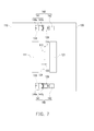
- FIG. 7 is a schematic view of a portable electronic device after assembled according to an embodiment of the present invention.
- the portable electronic device 100 further includes an assembling structure 140, which is disposed in the first body 110 by the first assembling unit 141, and is disposed in the second body 120 by the second assembling unit 142. Therefore, when the first side surface 114 and the second side surface 124 are close to each other, the first assembling unit 141 and the second assembling unit 142 can be assembled to each other.
- the first body 110 further has a first concave 116
- the first assembling unit 141 includes an assembling element 141 a and a restoring element 141b.
- the assembling element 141a for example, is a tenon, which is movably disposed in the first concave 116.
- the restoring element 141b for example, is a spring, which is sleeved on the tenon and leaned between the assembling element 141a and the first body 110.
- the second body 120 further has a second concave 126.
- the second assembling unit 142 for example, is a magnetic component or a magnetic conducting component, which is disposed in the second concave 126, and the assembling element 141 a is also a magnetic component or a magnetic conducting component, so when the assembling element 141a and the second assembling unit 142 are close to each other, a magnetic attractive force is generated therebetween.
- the assembling element 141a and the second assembling unit 142 having magnetic attraction therebetween make the assembling element 141 protruded out of the first concave 116 so as to be lodged in the second concave 126.
- the assembling element 141 a is hidden in the first side surface 114 of the first body 110, and the first body 110 shields the first concave 116 by the dust cover 118 such that the integration of the appearance can be maintained.
- the second body 120 can also shield the second concave 126 by a similar structure to achieve the above-mentioned effect.
- the assembling element 141 a is lodged in the second concave 126 due to the magnetic attractive force of the second assembling unit 142, and the restoring element 141b is deformed at the time, such that the first body 110 and the second body 120 are fixed together by the assembling structure 140 for the user to use under the statuses shown in FIG. 4 , FIG. 5 or FIG. 6 .
- the portable electronic device 100 thus can have enough structure strength.
- the restoring element 141b drives the assembling element 141a moving back in the first concave 116. It is noted that, the magnetic attractive force between the second assembling unit 142 and the assembling element 141 a is greater than the elastic force applied on the assembling element 141a by the restoring element 141b to ensure that the first assembling unit 141 can achieve the status shown in FIG. 7 .
- the number and the method of the first assembling unit 141 and the second assembling unit 142 respectively disposed on the first body 110 and the second body 120 are not limited herein. As shown in FIG. 7 , the first assembling unit 141 and the second assembling unit 142 of the present embodiment are respectively disposed in pair on the bodies close to one of the side surfaces and correspond to each other. However, designers may dispose the same assembling structures on the bodies correspondingly according to the assembling requirement between the bodies.
- the first body 110 further has a first electronic module 111 and a first connector 113 electrically connected to each other, and the first connector 113 is exposed by the first side surface 114.
- the second body 120 further has a second electronic module 121 and a second connector 123, and the second connector 123 is exposed by the second side surface 124.
- the first electronic module 111 and the second electronic module 121 are battery modules.
- the first connector 113 is connected to the second connector 123, such that the first electronic module 111 is electrically connected to the second electronic module 121.
- the first body 110 and the second body 120 can be backup power source for each other so as to supply power for emergency purposes when one of the bodies is in low-power status.
- FIG. 8 is a schematic view of a portable electronic device after assembled according to another embodiment of the present invention.
- the difference between the present embodiment and the above-mentioned embodiment is that, in the assembling structure 340 of the portable electronic device 300, the restoring element 341b of the first assembling unit 341 is a magnetic component or magnetic conducting component disposed in the first concave 116, and the restoring element 341b and the assembling element 141a have a magnetic attractive force therebetween.
- the assembling element 141a of the present embodiment achieves the restoring effect by the magnetic attractive force of the restoring element 341b toward the assembling element 141a. That is to say, when the first side surface 114 is close to the second side surface 124, the assembling element 141a is located between the restoring element 314b and the second assembling unit 142, and the magnetic attractive force between the second assembling unit 142 and the assembling element 141 a is greater than the magnetic attractive force between the restoring element 341b and the assembling element 141a, so as to ensure that the first assembling unit 341 achieves the status shown in FIG. 8 .
- the assembling element 141a moves back to the first concave 116 and is hidden in the first side surface 114 due to the magnetic attractive force of the restoring element 341 toward the assembling element 141a.
- FIG. 9 is a schematic view of a portable electronic device after assembled according to another embodiment of the present invention.
- the difference between the present embodiment and the above-mentioned embodiment is that the assembling element 441a of the first assembling unit 441 and the second assembling unit 442 are connector structures coupled to each other. That is to say, the first electronic module 111 and the second electronic module 121 are respectively disposed in the first body 110 and the second body 120.
- the first electronic module 111 is electrically connected to the assembling element 441a
- the second electronic module 121 is electrically connected to the second assembling unit 442.
- the assembling element 441 a when the assembling element 441 a is protruded out of the first concave 116 and is lodged in the second concave so as to be connected to the second assembling unit 442, the first electronic module 111 and the second electronic module 121 are electrically connected to each other by the assembling structure 440.
- the first body and the second body of the portable electronic device are separable and also can be reassembled, so as to provide the portable electronic device greater and more flexible operation status.
- the assembling structure includes the first assembling unit and the second assembling unit respectively disposed in the first body and the second body, so that when close to each other, the first body and the second body can be fixed together by the assembling units assembled to each other.
Landscapes
- Engineering & Computer Science (AREA)
- Theoretical Computer Science (AREA)
- Computer Hardware Design (AREA)
- Physics & Mathematics (AREA)
- Human Computer Interaction (AREA)
- General Engineering & Computer Science (AREA)
- General Physics & Mathematics (AREA)
- Microelectronics & Electronic Packaging (AREA)
- Mathematical Physics (AREA)
- Computer Networks & Wireless Communication (AREA)
- Telephone Set Structure (AREA)
- Battery Mounting, Suspending (AREA)
Abstract
Description
- The present invention relates to a portable electronic device and more particularly, to a portable electronic device which the bodies thereof are separable.
- To meet the requirement of a light, thin and compact portable electronic device nowadays, the volume of the device is rather limited. For the devices such as mobile phones or tablet PC, if a screen and a keypad are both disposed on the device, the size of the screen has to be reduced. In order to dispose a larger screen in the limited space, a touch screen has been developed recently. By integrating the keypad into the screen as an input interface of the portable electronic device, the cost of and the area occupied by a traditional keypad are saved.
- To meet operation demands of different applications, the touch screen displays the corresponding operation interfaces according to the execution demand of each application for a user to operate the functions of the applications by touching. For example, when the user activates a document editing program, a virtual keypad is displayed on the touch screen for the user to input characters. When the user activates a media player program, control keys such as display key, pause key, stop key, forward key, rewind key, etc., are displayed on the touch screen for the user to operate the functions of the media player program.
- However, the interfaces such as key pad, control keys, etc., displayed on the touch screen still occupy considerable display space of the screen, other contents are thus compressed which is harder for the user to read. Furthermore, when the user answers the phone by the portable electronic device, the touch screen is turned off to keep the user from touching the touch screen accidentally, so the user can not perform operations on the portable electronic device.
- Therefore, there is a need to develop a portable electronic device with greater screen display space and flexible usage to adapt all kinds of operation environments.
- The present invention provides a portable electronic device which the bodies thereof are separable so as to have more flexible operation status and greater operation range.
- A portable electronic device including a first body, a second body and an assembling structure is provided. The assembling structure includes a first assembling unit and a second assembling unit, wherein the first assembling unit is adapted to hidden in one of the first body and the second body. When the first body is close to the second body, the first assembling unit is protruded out of the first body or the second body, and is correspondingly assembled to the second assembling unit, such that the first body and the second body are fixed together.
- Based on the above, in the aforesaid embodiments of the present invention, the first body and the second body of the portable electronic device are separable so as to provide the portable electronic device greater and more flexible operation environment. Moreover, the assembling structure includes the first assembling unit and the second assembling unit respectively disposed in the first body and the second body, so that when close to each other, the first body and the second body can be fixed together by the assembling units assembled to each other.
- In order to make the aforementioned and other features and advantages of the invention more comprehensible, embodiments accompanying figures are described in detail below.
-
FIG. 1 is a schematic view of a portable electronic device according to an embodiment of the present invention. -
FIG. 2 is a schematic view of the portable electronic device inFig. 1 under another operation status. -
FIG. 3 is a usage scenario of the portable electronic device under the status ofFIG. 2 . -
FIG. 4 andFIG. 5 are schematic views respectively illustrating the statuses of the portable electronic device inFIG. 2 after assembled. -
FIG. 6 is a schematic view of a portable electronic device according to another embodiment of the present invention. -
FIG. 7 is a schematic view of a portable electronic device after assembled according to an embodiment of the present invention. -
FIG. 8 is a schematic view of a portable electronic device after assembled according to another embodiment of the present invention. -
FIG. 9 is a schematic view of a portable electronic device after assembled according to another embodiment of the present invention. -
FIG. 1 is a schematic view of a portable electronic device according to an embodiment of the present invention.Fig. 2 is a schematic view of the portable electronic device inFig. 1 under another operation status.FIG. 3 is a usage scenario of the portable electronic device under the status ofFIG. 2 . Referring toFIG. 1 to FIG. 3 , in the present embodiment, the portableelectronic device 100 includes afirst body 110 and asecond body 120, which achieve the stacked status shown inFIG. 1 by themagnetic assembling elements magnetic assembling elements FIG. 2 are achieved. Moreover, in the present embodiment, wireless transmission modules (not shown) can further be respectively disposed on thefirst body 110 and thesecond body 120 of the portableelectronic device 100 so that thefirst body 110 and thesecond body 120 can still be able to proceed data transmission when thefirst body 110 and thesecond body 120 are separated from each other. - The
first body 110 and thesecond body 120 respectively have afirst display surface 112 and asecond display surface 122, which respectively are touch screens. Then, the images displayed on thefirst display surface 112 and thesecond display surface 122 are varied according to a connecting condition between thefirst body 110 and thesecond body 120 and types of applications being executed. - For example, when the
first body 110 and thesecond body 120 of the portableelectronic device 100 are stacked together, the portableelectronic device 100 is operated as a mobile phone for a user to dial and answer phone calls or sending and receiving messages. Moreover, when the user uses the portableelectronic device 100 to answer a phone call, if the user needs to search some data such as phone numbers of other contacts or the location of the user himself, etc., thesecond body 120 can be removed from thefirst body 110, as shown inFIG. 3 , such that the user can answer the phone call by thefirst body 110 and search the needed data by operating thesecond body 120 at the same time. The search result can be transmitted back to thefirst body 110 from thesecond body 120 through the wireless connection between thefirst body 110 and thesecond body 120, so as to be transmitted to a user at the other side of the phone through the communicating connection of thefirst body 110. - Similarly, the
second body 120 of the present embodiment further has a photography module (not shown) at the back of thesecond display surface 122. When a user uses the portableelectronic device 100 to answer a phone call, if the user wants to take photos and share the photos, thesecond body 120 can be removed from thefirst body 110, such that the user can answer the phone call by thefirst body 110 and take photos by operating thesecond body 120 at the same time, and images taken by thesecond body 120 can be transmitted back to thefirst body 110 through the wireless connection between thefirst body 110 and thesecond body 120, so the images can be transmitted to a user at the other side of the phone through communicating connection of thefirst body 110. - The above-mentioned usage scenarios are given as examples, and are not intended to limit the scope of the present invention. Users may flexibly use the
first body 110 and thesecond body 120 to execute the needed functions according to actual demands. The present invention is not limited herein. - Furthermore, the present invention does not limit the types of the portable
electronic device 100. The above-mentionedfirst body 110 and thesecond body 120 can be a thin electronic device such as mobile phone, personal digital assistant (PDA) or tablet PC, etc. In addition, thefirst body 110 and thesecond body 120 can be operated independently and also can be stacked and operated as a single device. -
FIG. 4 andFIG. 5 are schematic views respectively illustrating the statuses of the portable electronic device inFIG. 2 after assembled. Referring toFIG. 2 ,FIG. 4 andFIG. 5 , in the present embodiment, thefirst body 110 has afirst side surface 114 adjoining thefirst display surface 112, and thesecond body 120 has asecond side surface 124 adjoining thesecond display surface 122, wherein thefirst display surface 112 and thefirst side surface 114 include an obtuse angle, and thesecond display surface 122 and thesecond side surface 124 include an obtuse angle, such that thefirst body 110 and thesecond body 120 respectively have, for the view angle of the front view shown inFIG. 2 , features of trapezium contours. Thus, when thefirst side surface 114 and thesecond side surface 124 are assembled to each other, thefirst display surface 112 and thesecond display surface 122 include an obtuse angle, which shows statuses of tilting relative to each other and not located at the same geometric plane as shown inFIG. 4 andFIG. 5 . - For example, referring to
FIG. 4 , by using the effect of thefirst display surface 112 raised relative to thesecond display surface 122, the portableelectronic device 100 can now activate the display/operation mode as note books, and the corresponding key patterns generated by the user operating thesecond display surface 122 can operate the messages displayed on thefirst display surface 112. - Similarly, referring to
FIG. 5 , because thefirst display surface 112 and thesecond display surface 122 include a included angle which is not 180 degree, thefirst body 110 and thesecond body 120 are assembled by the side surfaces thereof and generate the effect as opening a book after being erected, so as to meet the view angles and reading habits of users. - Of course, as shown in
FIG. 2 , the contour of thefirst body 110 has fourfirst side surfaces 114, same as thesecond body 120, surrounding thefirst display surface 112, so the above-mentioned embodiment only describes the operation status and effect after one of thefirst side surface 114 is assembled to one of thesecond side surface 124. Designers may assemble thefirst body 110 and thesecond body 120 to each other with any surfaces thereof according to the operation environment and requirements, so as to generate the required operation status and effect. The present invention is not limited herein. -
FIG. 6 is a schematic view of a portable electronic device according to another embodiment of the present invention. Referring toFIG. 6 , the difference between the present embodiment and the above-mentioned embodiment is that, in the present embodiment, thefirst display surface 212 of thefirst body 210 is perpendicular to thefirst side surface 214, and thesecond display surface 222 of thesecond body 220 is perpendicular to thesecond display surface 224. Accordingly, after thefirst body 210 and thesecond body 220 are assembled to each other respectively by thefirst side surface 214 and thesecond side surface 224 thereof, a tablet structure as shown inFIG. 6 is formed. At the time, thefirst display surface 212 and thesecond display surface 222 are located at the same geometric plane, so the portableelectronic device 200 can have greater display area for users to watch. - Based on the above, designers may assemble or arrange the first body and the second body with different connecting relationships by the contours of the bodies.
-
FIG. 7 is a schematic view of a portable electronic device after assembled according to an embodiment of the present invention. Referring toFIG. 2 andFIG. 7 , in the present embodiment, the portableelectronic device 100 further includes an assemblingstructure 140, which is disposed in thefirst body 110 by thefirst assembling unit 141, and is disposed in thesecond body 120 by thesecond assembling unit 142. Therefore, when thefirst side surface 114 and thesecond side surface 124 are close to each other, thefirst assembling unit 141 and thesecond assembling unit 142 can be assembled to each other. - In addition, the
first body 110 further has a first concave 116, and thefirst assembling unit 141 includes an assemblingelement 141 a and a restoringelement 141b. The assemblingelement 141a, for example, is a tenon, which is movably disposed in the first concave 116. The restoringelement 141b, for example, is a spring, which is sleeved on the tenon and leaned between the assemblingelement 141a and thefirst body 110. On the other hand, thesecond body 120 further has a second concave 126. Thesecond assembling unit 142, for example, is a magnetic component or a magnetic conducting component, which is disposed in the second concave 126, and the assemblingelement 141 a is also a magnetic component or a magnetic conducting component, so when the assemblingelement 141a and thesecond assembling unit 142 are close to each other, a magnetic attractive force is generated therebetween. - Accordingly, when the
first body 110 is close to thesecond side surface 124 of the second body with thefirst side surface 114, the assemblingelement 141a and thesecond assembling unit 142 having magnetic attraction therebetween make the assemblingelement 141 protruded out of the first concave 116 so as to be lodged in the second concave 126. In other words, when thefirst body 110 and thesecond body 120 are separated, the assemblingelement 141 a is hidden in thefirst side surface 114 of thefirst body 110, and thefirst body 110 shields the first concave 116 by thedust cover 118 such that the integration of the appearance can be maintained. Similarly, thesecond body 120 can also shield the second concave 126 by a similar structure to achieve the above-mentioned effect. Until the status shown inFIG. 7 , the assemblingelement 141 a is lodged in the second concave 126 due to the magnetic attractive force of thesecond assembling unit 142, and the restoringelement 141b is deformed at the time, such that thefirst body 110 and thesecond body 120 are fixed together by the assemblingstructure 140 for the user to use under the statuses shown inFIG. 4 ,FIG. 5 or FIG. 6 . The portableelectronic device 100 thus can have enough structure strength. - On the contrary, when the
first body 110 and thesecond body 120 are separated again, the restoringelement 141b drives the assemblingelement 141a moving back in the first concave 116. It is noted that, the magnetic attractive force between thesecond assembling unit 142 and the assemblingelement 141 a is greater than the elastic force applied on the assemblingelement 141a by the restoringelement 141b to ensure that thefirst assembling unit 141 can achieve the status shown inFIG. 7 . - The number and the method of the
first assembling unit 141 and thesecond assembling unit 142 respectively disposed on thefirst body 110 and thesecond body 120 are not limited herein. As shown inFIG. 7 , thefirst assembling unit 141 and thesecond assembling unit 142 of the present embodiment are respectively disposed in pair on the bodies close to one of the side surfaces and correspond to each other. However, designers may dispose the same assembling structures on the bodies correspondingly according to the assembling requirement between the bodies. - In addition, the
first body 110 further has a firstelectronic module 111 and afirst connector 113 electrically connected to each other, and thefirst connector 113 is exposed by thefirst side surface 114. Thesecond body 120 further has a secondelectronic module 121 and asecond connector 123, and thesecond connector 123 is exposed by thesecond side surface 124. In the present embodiment, the firstelectronic module 111 and the secondelectronic module 121, for example, are battery modules. When thefirst side surface 114 contacts thesecond side surface 124, thefirst connector 113 is connected to thesecond connector 123, such that the firstelectronic module 111 is electrically connected to the secondelectronic module 121. In other words, thefirst body 110 and thesecond body 120 can be backup power source for each other so as to supply power for emergency purposes when one of the bodies is in low-power status. -
FIG. 8 is a schematic view of a portable electronic device after assembled according to another embodiment of the present invention. Referring toFIG. 8 , the difference between the present embodiment and the above-mentioned embodiment is that, in the assemblingstructure 340 of the portable electronic device 300, the restoringelement 341b of thefirst assembling unit 341 is a magnetic component or magnetic conducting component disposed in the first concave 116, and the restoringelement 341b and the assemblingelement 141a have a magnetic attractive force therebetween. - In other words, the assembling
element 141a of the present embodiment achieves the restoring effect by the magnetic attractive force of the restoringelement 341b toward the assemblingelement 141a. That is to say, when thefirst side surface 114 is close to thesecond side surface 124, the assemblingelement 141a is located between the restoring element 314b and thesecond assembling unit 142, and the magnetic attractive force between thesecond assembling unit 142 and the assemblingelement 141 a is greater than the magnetic attractive force between the restoringelement 341b and the assemblingelement 141a, so as to ensure that thefirst assembling unit 341 achieves the status shown inFIG. 8 . Once thefirst body 110 and thesecond body 120 are separated, which means the magnetic attractive force between thesecond assembling unit 142 and the assemblingelement 141 a is vanished, the assemblingelement 141a moves back to the first concave 116 and is hidden in thefirst side surface 114 due to the magnetic attractive force of the restoringelement 341 toward the assemblingelement 141a. -
FIG. 9 is a schematic view of a portable electronic device after assembled according to another embodiment of the present invention. Referring toFIG. 9 , the difference between the present embodiment and the above-mentioned embodiment is that the assemblingelement 441a of thefirst assembling unit 441 and thesecond assembling unit 442 are connector structures coupled to each other. That is to say, the firstelectronic module 111 and the secondelectronic module 121 are respectively disposed in thefirst body 110 and thesecond body 120. The firstelectronic module 111 is electrically connected to the assemblingelement 441a, and the secondelectronic module 121 is electrically connected to thesecond assembling unit 442. Accordingly, when the assemblingelement 441 a is protruded out of the first concave 116 and is lodged in the second concave so as to be connected to thesecond assembling unit 442, the firstelectronic module 111 and the secondelectronic module 121 are electrically connected to each other by the assemblingstructure 440. - In sum, in the aforesaid embodiments of the present invention, the first body and the second body of the portable electronic device are separable and also can be reassembled, so as to provide the portable electronic device greater and more flexible operation status. Moreover, the assembling structure includes the first assembling unit and the second assembling unit respectively disposed in the first body and the second body, so that when close to each other, the first body and the second body can be fixed together by the assembling units assembled to each other.
Claims (10)
- A portable electronic device (100), comprising:a first body (110);a second body (120);an assembling structure (140), comprising:a first assembling unit (141), adapted to hidden in one of the first body (110) and the second body (120); anda second assembling unit (142), disposed and hidden in another one of the first body (110) and the second body (120), wherein when the first body (110) is close to the second body (120), the first assembling unit (141) is protruded out of the first body (110) or the second body (120), and assembled to the second assembling unit (142), such that the first body (110) and the second body (120) are fixed to each other.
- The portable electronic device (100) as claimed in claim 1, wherein the first body (110) has a first display surface (112) and a first side surface (114) adjoining the first display surface (112), the second body (120) has a second display surface (122) and a second side surface (124) adjoining the second display surface (122), the first assembling unit (141) is adapted to protruded out or hidden in the first side surface (114) of the first body (110), the second assembling unit (142) is hidden in the second side surface (124) of the second body (120), when the first body (110) and the second body (120) are fixed together, the first side surface (114) is overlapped with the second side surface (124).
- The portable electronic device (100) as claimed in claim 2, wherein when the first side surface (114) is overlapped with the second side surface (124), the first display surface (112) and the second display surface (122) include an obtuse angle.
- The portable electronic device (100) as claimed in claim 2, wherein the first assembling unit (141) comprises:an assembling element (141a), movably disposed in the first body (110); anda restoring element (141b), disposed in the first body (110), the restoring element (141b) driving the assembling element (141a) to be hidden in the first side surface (114) of the first body (110).
- The portable electronic device (100) as claimed in claim 4, wherein the second assembling unit (142) and the assembling element (141a) have magnetic attraction therebetween.
- The portable electronic device (100) as claimed in claim 5, wherein the restoring element (141b) is a spring, leaning between the assembling element (141a) and the first body (110), when the first side surface (114) is close to the second side surface (124), magnetic attractive force between the second assembling unit (142) and the assembling element (141a) is greater than elastic force applied on the assembling element (141a) by the spring.
- The portable electronic device (100) as claimed in claim 5, wherein the assembling element (141a) and the restoring element (141b) have magnetic attraction therebetween, when the first side surface (114) is close to the second side surface (124), the assembling element (141a) is located between the restoring element (141b) and the second assembling unit (142), and magnetic attractive force between the second assembling unit (142) and the assembling element (141a) is greater than magnetic attractive force between the restoring element (141b) and the assembling element (142).
- The portable electronic device (100) as claimed in claim 1, wherein the first assembling unit (141) and the second assembling unit (142) are connector structures coupled to each other.
- The portable electronic device (100) as claimed in claim 8, further comprising a first electronic module (111) and a second electronic module (121), respectively disposed in the first body (110) and the second body (120), wherein the first electronic module (111) is electrically connected to the first assembling unit (141), the second electronic module (121) is electrically connected to the second assembling unit (142), when the first assembling unit (141) is assembled to the second assembling unit (142), the first electronic module (111) and the second electronic module (121) are electrically connected to each other by the assembling structure (140).
- The portable electronic device (100) as claimed in claim 1, wherein the first body (110) further has a first electronic module (111) and a first connector (113) electrically connected to each other, and the first connector (113) is exposed by the first side surface (114), and the second body (120)further has a second electronic module (121) and a second connector (123) electrically connected to each other, and the second connector (123) is exposed by the second side surface (124), when the first side surface (114) contacts the second side surface (124), the first connector (113) is connected to the second connector (123), such that the first electronic module (111) is electrically connected to the second electronic module (121).
Applications Claiming Priority (2)
| Application Number | Priority Date | Filing Date | Title |
|---|---|---|---|
| US201261659325P | 2012-06-13 | 2012-06-13 | |
| TW101141873A TW201351102A (en) | 2012-06-13 | 2012-11-09 | Portable electronic device |
Publications (2)
| Publication Number | Publication Date |
|---|---|
| EP2674832A2 true EP2674832A2 (en) | 2013-12-18 |
| EP2674832A3 EP2674832A3 (en) | 2014-10-08 |
Family
ID=47598675
Family Applications (1)
| Application Number | Title | Priority Date | Filing Date |
|---|---|---|---|
| EP13150657.8A Withdrawn EP2674832A3 (en) | 2012-06-13 | 2013-01-09 | Portable electronic device |
Country Status (2)
| Country | Link |
|---|---|
| US (1) | US20130335925A1 (en) |
| EP (1) | EP2674832A3 (en) |
Families Citing this family (1)
| Publication number | Priority date | Publication date | Assignee | Title |
|---|---|---|---|---|
| CN106814801A (en) * | 2015-11-27 | 2017-06-09 | 英业达科技有限公司 | Portable computing device |
Family Cites Families (15)
| Publication number | Priority date | Publication date | Assignee | Title |
|---|---|---|---|---|
| US6700773B1 (en) * | 2000-11-03 | 2004-03-02 | Revolutionary Learning Systems, Inc. | Method and apparatus for implementing a configurable personal computing device |
| TW555118U (en) * | 2001-11-09 | 2003-09-21 | Clevo Co | Rotatory monitor device |
| JP2004310659A (en) * | 2003-04-10 | 2004-11-04 | Matsushita Electric Ind Co Ltd | Information processing device |
| US6929291B2 (en) * | 2003-07-28 | 2005-08-16 | Inventec Corp. | Magnetic lock |
| TW200530784A (en) * | 2004-03-15 | 2005-09-16 | Asustek Comp Inc | Magnetic lock device |
| US7283353B1 (en) * | 2004-09-30 | 2007-10-16 | Aurellius Jordan | Screen extenders |
| US8120716B2 (en) * | 2005-06-16 | 2012-02-21 | Audiovox Corporation | Vehicle entertainment system including monitor for rear view enhancement |
| TWI347163B (en) * | 2008-09-19 | 2011-08-11 | Asustek Comp Inc | Foldable electronic device and pivot mechanism thereof |
| CN101872212B (en) * | 2009-04-23 | 2013-08-07 | 鸿富锦精密工业(深圳)有限公司 | Notebook computer and connecting device thereof |
| TWM377045U (en) * | 2009-11-13 | 2010-03-21 | Quanta Comp Inc | Fixing structure and electronic device using the same |
| KR101084651B1 (en) * | 2010-03-05 | 2011-11-17 | 엘지전자 주식회사 | Expansion module and portable electronic device having same |
| US8264310B2 (en) * | 2010-09-17 | 2012-09-11 | Apple Inc. | Accessory device for peek mode |
| TWI548250B (en) * | 2010-11-15 | 2016-09-01 | 富智康(香港)有限公司 | Portable electronic device |
| US9335793B2 (en) * | 2011-01-31 | 2016-05-10 | Apple Inc. | Cover attachment with flexible display |
| US8654518B2 (en) * | 2012-01-20 | 2014-02-18 | Htc Corporation | Electronic apparatus |
-
2012
- 2012-12-17 US US13/716,224 patent/US20130335925A1/en not_active Abandoned
-
2013
- 2013-01-09 EP EP13150657.8A patent/EP2674832A3/en not_active Withdrawn
Non-Patent Citations (1)
| Title |
|---|
| None |
Also Published As
| Publication number | Publication date |
|---|---|
| US20130335925A1 (en) | 2013-12-19 |
| EP2674832A3 (en) | 2014-10-08 |
Similar Documents
| Publication | Publication Date | Title |
|---|---|---|
| CN103488251A (en) | Portable electronic device | |
| KR102668216B1 (en) | Foldable electronic device including hinge assembly | |
| KR102104141B1 (en) | Flux fountain | |
| US8279592B2 (en) | Electronic device | |
| TWI512432B (en) | Electronic device | |
| EP3699724B1 (en) | Electronic device comprising flexible hinge | |
| TWI410824B (en) | Electronic device with the module integrating display unit and input unit | |
| JP5970248B2 (en) | Electronics | |
| US20220004228A1 (en) | Electronic device comprising dual display and keyboard | |
| US8634196B2 (en) | Locking mechanism and electronic device | |
| MX2008009361A (en) | Tactile touchscreen for electronic device. | |
| JP2021526267A (en) | Mobile terminals and electronic devices equipped with mobile terminals | |
| US7486503B1 (en) | Portable electronic device structure | |
| US7676242B2 (en) | Compact and durable thin smartphone | |
| CN209748968U (en) | Protective shell and electronic equipment with same | |
| CN117223277A (en) | Electronic devices including hinged covers | |
| KR20190026024A (en) | Mobile terminal | |
| MX2008009861A (en) | Tactile touchscreen for electronic device. | |
| KR20110113243A (en) | Mobile terminal | |
| KR20220149338A (en) | Electronic device including hinge cover | |
| US20130335925A1 (en) | Portable electronic device | |
| JP5073072B2 (en) | Electronics | |
| CN105027247A (en) | electronic device | |
| CN110413045B (en) | Electronic assembly | |
| US8441455B2 (en) | Touch control device |
Legal Events
| Date | Code | Title | Description |
|---|---|---|---|
| PUAI | Public reference made under article 153(3) epc to a published international application that has entered the european phase |
Free format text: ORIGINAL CODE: 0009012 |
|
| AK | Designated contracting states |
Kind code of ref document: A2 Designated state(s): AL AT BE BG CH CY CZ DE DK EE ES FI FR GB GR HR HU IE IS IT LI LT LU LV MC MK MT NL NO PL PT RO RS SE SI SK SM TR |
|
| AX | Request for extension of the european patent |
Extension state: BA ME |
|
| PUAL | Search report despatched |
Free format text: ORIGINAL CODE: 0009013 |
|
| AK | Designated contracting states |
Kind code of ref document: A3 Designated state(s): AL AT BE BG CH CY CZ DE DK EE ES FI FR GB GR HR HU IE IS IT LI LT LU LV MC MK MT NL NO PL PT RO RS SE SI SK SM TR |
|
| AX | Request for extension of the european patent |
Extension state: BA ME |
|
| RIC1 | Information provided on ipc code assigned before grant |
Ipc: G06F 1/16 20060101AFI20140901BHEP |
|
| STAA | Information on the status of an ep patent application or granted ep patent |
Free format text: STATUS: THE APPLICATION IS DEEMED TO BE WITHDRAWN |
|
| 18D | Application deemed to be withdrawn |
Effective date: 20150409 |