EP2674697A1 - A plate heat exchanger - Google Patents
A plate heat exchanger Download PDFInfo
- Publication number
- EP2674697A1 EP2674697A1 EP12171918.1A EP12171918A EP2674697A1 EP 2674697 A1 EP2674697 A1 EP 2674697A1 EP 12171918 A EP12171918 A EP 12171918A EP 2674697 A1 EP2674697 A1 EP 2674697A1
- Authority
- EP
- European Patent Office
- Prior art keywords
- fluid
- evaporator
- injector
- temperature
- arrangement
- Prior art date
- Legal status (The legal status is an assumption and is not a legal conclusion. Google has not performed a legal analysis and makes no representation as to the accuracy of the status listed.)
- Granted
Links
Images



Classifications
-
- F—MECHANICAL ENGINEERING; LIGHTING; HEATING; WEAPONS; BLASTING
- F25—REFRIGERATION OR COOLING; COMBINED HEATING AND REFRIGERATION SYSTEMS; HEAT PUMP SYSTEMS; MANUFACTURE OR STORAGE OF ICE; LIQUEFACTION SOLIDIFICATION OF GASES
- F25B—REFRIGERATION MACHINES, PLANTS OR SYSTEMS; COMBINED HEATING AND REFRIGERATION SYSTEMS; HEAT PUMP SYSTEMS
- F25B49/00—Arrangement or mounting of control or safety devices
- F25B49/02—Arrangement or mounting of control or safety devices for compression type machines, plants or systems
-
- F—MECHANICAL ENGINEERING; LIGHTING; HEATING; WEAPONS; BLASTING
- F25—REFRIGERATION OR COOLING; COMBINED HEATING AND REFRIGERATION SYSTEMS; HEAT PUMP SYSTEMS; MANUFACTURE OR STORAGE OF ICE; LIQUEFACTION SOLIDIFICATION OF GASES
- F25B—REFRIGERATION MACHINES, PLANTS OR SYSTEMS; COMBINED HEATING AND REFRIGERATION SYSTEMS; HEAT PUMP SYSTEMS
- F25B39/00—Evaporators; Condensers
- F25B39/02—Evaporators
- F25B39/022—Evaporators with plate-like or laminated elements
-
- F—MECHANICAL ENGINEERING; LIGHTING; HEATING; WEAPONS; BLASTING
- F25—REFRIGERATION OR COOLING; COMBINED HEATING AND REFRIGERATION SYSTEMS; HEAT PUMP SYSTEMS; MANUFACTURE OR STORAGE OF ICE; LIQUEFACTION SOLIDIFICATION OF GASES
- F25B—REFRIGERATION MACHINES, PLANTS OR SYSTEMS; COMBINED HEATING AND REFRIGERATION SYSTEMS; HEAT PUMP SYSTEMS
- F25B39/00—Evaporators; Condensers
- F25B39/02—Evaporators
- F25B39/028—Evaporators having distributing means
-
- F—MECHANICAL ENGINEERING; LIGHTING; HEATING; WEAPONS; BLASTING
- F25—REFRIGERATION OR COOLING; COMBINED HEATING AND REFRIGERATION SYSTEMS; HEAT PUMP SYSTEMS; MANUFACTURE OR STORAGE OF ICE; LIQUEFACTION SOLIDIFICATION OF GASES
- F25B—REFRIGERATION MACHINES, PLANTS OR SYSTEMS; COMBINED HEATING AND REFRIGERATION SYSTEMS; HEAT PUMP SYSTEMS
- F25B41/00—Fluid-circulation arrangements
- F25B41/30—Expansion means; Dispositions thereof
- F25B41/385—Dispositions with two or more expansion means arranged in parallel on a refrigerant line leading to the same evaporator
-
- F—MECHANICAL ENGINEERING; LIGHTING; HEATING; WEAPONS; BLASTING
- F28—HEAT EXCHANGE IN GENERAL
- F28D—HEAT-EXCHANGE APPARATUS, NOT PROVIDED FOR IN ANOTHER SUBCLASS, IN WHICH THE HEAT-EXCHANGE MEDIA DO NOT COME INTO DIRECT CONTACT
- F28D1/00—Heat-exchange apparatus having stationary conduit assemblies for one heat-exchange medium only, the media being in contact with different sides of the conduit wall, in which the other heat-exchange medium is a large body of fluid, e.g. domestic or motor car radiators
- F28D1/02—Heat-exchange apparatus having stationary conduit assemblies for one heat-exchange medium only, the media being in contact with different sides of the conduit wall, in which the other heat-exchange medium is a large body of fluid, e.g. domestic or motor car radiators with heat-exchange conduits immersed in the body of fluid
- F28D1/03—Heat-exchange apparatus having stationary conduit assemblies for one heat-exchange medium only, the media being in contact with different sides of the conduit wall, in which the other heat-exchange medium is a large body of fluid, e.g. domestic or motor car radiators with heat-exchange conduits immersed in the body of fluid with plate-like or laminated conduits
- F28D1/0308—Heat-exchange apparatus having stationary conduit assemblies for one heat-exchange medium only, the media being in contact with different sides of the conduit wall, in which the other heat-exchange medium is a large body of fluid, e.g. domestic or motor car radiators with heat-exchange conduits immersed in the body of fluid with plate-like or laminated conduits the conduits being formed by paired plates touching each other
-
- F—MECHANICAL ENGINEERING; LIGHTING; HEATING; WEAPONS; BLASTING
- F28—HEAT EXCHANGE IN GENERAL
- F28D—HEAT-EXCHANGE APPARATUS, NOT PROVIDED FOR IN ANOTHER SUBCLASS, IN WHICH THE HEAT-EXCHANGE MEDIA DO NOT COME INTO DIRECT CONTACT
- F28D1/00—Heat-exchange apparatus having stationary conduit assemblies for one heat-exchange medium only, the media being in contact with different sides of the conduit wall, in which the other heat-exchange medium is a large body of fluid, e.g. domestic or motor car radiators
- F28D1/02—Heat-exchange apparatus having stationary conduit assemblies for one heat-exchange medium only, the media being in contact with different sides of the conduit wall, in which the other heat-exchange medium is a large body of fluid, e.g. domestic or motor car radiators with heat-exchange conduits immersed in the body of fluid
- F28D1/03—Heat-exchange apparatus having stationary conduit assemblies for one heat-exchange medium only, the media being in contact with different sides of the conduit wall, in which the other heat-exchange medium is a large body of fluid, e.g. domestic or motor car radiators with heat-exchange conduits immersed in the body of fluid with plate-like or laminated conduits
- F28D1/0308—Heat-exchange apparatus having stationary conduit assemblies for one heat-exchange medium only, the media being in contact with different sides of the conduit wall, in which the other heat-exchange medium is a large body of fluid, e.g. domestic or motor car radiators with heat-exchange conduits immersed in the body of fluid with plate-like or laminated conduits the conduits being formed by paired plates touching each other
- F28D1/0325—Heat-exchange apparatus having stationary conduit assemblies for one heat-exchange medium only, the media being in contact with different sides of the conduit wall, in which the other heat-exchange medium is a large body of fluid, e.g. domestic or motor car radiators with heat-exchange conduits immersed in the body of fluid with plate-like or laminated conduits the conduits being formed by paired plates touching each other the plates having lateral openings therein for circulation of the heat-exchange medium from one conduit to another
- F28D1/0333—Heat-exchange apparatus having stationary conduit assemblies for one heat-exchange medium only, the media being in contact with different sides of the conduit wall, in which the other heat-exchange medium is a large body of fluid, e.g. domestic or motor car radiators with heat-exchange conduits immersed in the body of fluid with plate-like or laminated conduits the conduits being formed by paired plates touching each other the plates having lateral openings therein for circulation of the heat-exchange medium from one conduit to another the plates having integrated connecting members
-
- F—MECHANICAL ENGINEERING; LIGHTING; HEATING; WEAPONS; BLASTING
- F28—HEAT EXCHANGE IN GENERAL
- F28D—HEAT-EXCHANGE APPARATUS, NOT PROVIDED FOR IN ANOTHER SUBCLASS, IN WHICH THE HEAT-EXCHANGE MEDIA DO NOT COME INTO DIRECT CONTACT
- F28D9/00—Heat-exchange apparatus having stationary plate-like or laminated conduit assemblies for both heat-exchange media, the media being in contact with different sides of a conduit wall
-
- F—MECHANICAL ENGINEERING; LIGHTING; HEATING; WEAPONS; BLASTING
- F28—HEAT EXCHANGE IN GENERAL
- F28D—HEAT-EXCHANGE APPARATUS, NOT PROVIDED FOR IN ANOTHER SUBCLASS, IN WHICH THE HEAT-EXCHANGE MEDIA DO NOT COME INTO DIRECT CONTACT
- F28D9/00—Heat-exchange apparatus having stationary plate-like or laminated conduit assemblies for both heat-exchange media, the media being in contact with different sides of a conduit wall
- F28D9/0031—Heat-exchange apparatus having stationary plate-like or laminated conduit assemblies for both heat-exchange media, the media being in contact with different sides of a conduit wall the conduits for one heat-exchange medium being formed by paired plates touching each other
- F28D9/0043—Heat-exchange apparatus having stationary plate-like or laminated conduit assemblies for both heat-exchange media, the media being in contact with different sides of a conduit wall the conduits for one heat-exchange medium being formed by paired plates touching each other the plates having openings therein for circulation of at least one heat-exchange medium from one conduit to another
- F28D9/005—Heat-exchange apparatus having stationary plate-like or laminated conduit assemblies for both heat-exchange media, the media being in contact with different sides of a conduit wall the conduits for one heat-exchange medium being formed by paired plates touching each other the plates having openings therein for circulation of at least one heat-exchange medium from one conduit to another the plates having openings therein for both heat-exchange media
-
- F—MECHANICAL ENGINEERING; LIGHTING; HEATING; WEAPONS; BLASTING
- F28—HEAT EXCHANGE IN GENERAL
- F28F—DETAILS OF HEAT-EXCHANGE AND HEAT-TRANSFER APPARATUS, OF GENERAL APPLICATION
- F28F27/00—Control arrangements or safety devices specially adapted for heat-exchange or heat-transfer apparatus
- F28F27/02—Control arrangements or safety devices specially adapted for heat-exchange or heat-transfer apparatus for controlling the distribution of heat-exchange media between different channels
-
- F—MECHANICAL ENGINEERING; LIGHTING; HEATING; WEAPONS; BLASTING
- F28—HEAT EXCHANGE IN GENERAL
- F28F—DETAILS OF HEAT-EXCHANGE AND HEAT-TRANSFER APPARATUS, OF GENERAL APPLICATION
- F28F9/00—Casings; Header boxes; Auxiliary supports for elements; Auxiliary members within casings
- F28F9/02—Header boxes; End plates
- F28F9/026—Header boxes; End plates with static flow control means, e.g. with means for uniformly distributing heat exchange media into conduits
- F28F9/027—Header boxes; End plates with static flow control means, e.g. with means for uniformly distributing heat exchange media into conduits in the form of distribution pipes
-
- F—MECHANICAL ENGINEERING; LIGHTING; HEATING; WEAPONS; BLASTING
- F25—REFRIGERATION OR COOLING; COMBINED HEATING AND REFRIGERATION SYSTEMS; HEAT PUMP SYSTEMS; MANUFACTURE OR STORAGE OF ICE; LIQUEFACTION SOLIDIFICATION OF GASES
- F25B—REFRIGERATION MACHINES, PLANTS OR SYSTEMS; COMBINED HEATING AND REFRIGERATION SYSTEMS; HEAT PUMP SYSTEMS
- F25B2600/00—Control issues
- F25B2600/21—Refrigerant outlet evaporator temperature
-
- F—MECHANICAL ENGINEERING; LIGHTING; HEATING; WEAPONS; BLASTING
- F25—REFRIGERATION OR COOLING; COMBINED HEATING AND REFRIGERATION SYSTEMS; HEAT PUMP SYSTEMS; MANUFACTURE OR STORAGE OF ICE; LIQUEFACTION SOLIDIFICATION OF GASES
- F25B—REFRIGERATION MACHINES, PLANTS OR SYSTEMS; COMBINED HEATING AND REFRIGERATION SYSTEMS; HEAT PUMP SYSTEMS
- F25B2600/00—Control issues
- F25B2600/25—Control of valves
- F25B2600/2513—Expansion valves
-
- F—MECHANICAL ENGINEERING; LIGHTING; HEATING; WEAPONS; BLASTING
- F25—REFRIGERATION OR COOLING; COMBINED HEATING AND REFRIGERATION SYSTEMS; HEAT PUMP SYSTEMS; MANUFACTURE OR STORAGE OF ICE; LIQUEFACTION SOLIDIFICATION OF GASES
- F25B—REFRIGERATION MACHINES, PLANTS OR SYSTEMS; COMBINED HEATING AND REFRIGERATION SYSTEMS; HEAT PUMP SYSTEMS
- F25B2700/00—Sensing or detecting of parameters; Sensors therefor
- F25B2700/13—Mass flow of refrigerants
- F25B2700/135—Mass flow of refrigerants through the evaporator
-
- F—MECHANICAL ENGINEERING; LIGHTING; HEATING; WEAPONS; BLASTING
- F25—REFRIGERATION OR COOLING; COMBINED HEATING AND REFRIGERATION SYSTEMS; HEAT PUMP SYSTEMS; MANUFACTURE OR STORAGE OF ICE; LIQUEFACTION SOLIDIFICATION OF GASES
- F25B—REFRIGERATION MACHINES, PLANTS OR SYSTEMS; COMBINED HEATING AND REFRIGERATION SYSTEMS; HEAT PUMP SYSTEMS
- F25B2700/00—Sensing or detecting of parameters; Sensors therefor
- F25B2700/19—Pressures
- F25B2700/197—Pressures of the evaporator
-
- F—MECHANICAL ENGINEERING; LIGHTING; HEATING; WEAPONS; BLASTING
- F25—REFRIGERATION OR COOLING; COMBINED HEATING AND REFRIGERATION SYSTEMS; HEAT PUMP SYSTEMS; MANUFACTURE OR STORAGE OF ICE; LIQUEFACTION SOLIDIFICATION OF GASES
- F25B—REFRIGERATION MACHINES, PLANTS OR SYSTEMS; COMBINED HEATING AND REFRIGERATION SYSTEMS; HEAT PUMP SYSTEMS
- F25B2700/00—Sensing or detecting of parameters; Sensors therefor
- F25B2700/21—Temperatures
- F25B2700/2117—Temperatures of an evaporator
- F25B2700/21175—Temperatures of an evaporator of the refrigerant at the outlet of the evaporator
Definitions
- the present invention refers generally to a system for dynamic control of the operation of an evaporator. Further, the invention refers to a method for dynamic control of the operation of an evaporator.
- the present invention refers generally to a system comprising an evaporator and in particular to an evaporator in the form of a plate heat exchanger.
- an evaporator is designed for evaporation of a fluid, such as a cooling agent, for various applications, such as air conditioning, cooling systems, heat pump systems, etc.
- a fluid such as a cooling agent
- the evaporator may be used in a two-phase system handling a fluid in a liquid form as well as in a gaseous form.
- this may by way of example include a plate package, which includes a number of first and second heat exchanger plates.
- the plates are permanently joined to each other and arranged side by side in such a way that a first plate interspace, forming a first fluid passage, is formed between each pair of adjacent first heat exchanger plates and second heat exchanger plates, and a second plate interspace, forming a second fluid passage, between each pair of adjacent second heat exchanger plates and first heat exchanger plates.
- the first plate interspaces and the second plate interspaces are separated from each other and provided side by side in an alternating order in the plate package.
- each heat exchanger plate has at least a first porthole and a second porthole, wherein the first portholes form a first inlet channel to the first plate interspaces and the second portholes form a first outlet channel from the first plate interspaces and wherein the plate package includes a separate space for each of said first plate interspaces, which space is closed to the second plate interspaces.
- a first fluid such as a cooling agent
- a partly evaporated fluid at one end of the first inlet channel, i.e. the first port hole, for further distribution along the first inlet channel and further into each of the individual first plate interspaces during evaporation into a gaseous form.
- the pressure drop of the cooling agent may increase with the distance from the inlet to the first inlet channel, whereby the distribution of the first fluid between the individual plate interspaces will be affected. It is known that the angular flow change that the droplets of the first fluid must undergo when entering the individual plate interspaces from the first inlet channel contributes to an uneven distribution. Yet another influencing parameter is dimensional differences between the individual first plate interspaces, resulting in that each first plate interspace has its unique efficiency. It is also to be known that the operation and performance of an individual first plate interspace depends on its position in a plate package. The outer most first plate interspaces on each side of the plate package tend to behave different than those in the middle of the plate package.
- the purpose of operating the evaporator as close to a superheating set-point temperature as possible no matter operation duty is of importance to get as high utilization factor as possible. Thus, it is of economic importance. Further, it has an influence to other components cooperating with the evaporator, such as a compressor, since compressors normally are sensitive to liquid content. Any droplets remaining in the evaporated fluid when reaching the inlet of the compressor may damage the same. Also, there is an economical interest of operating the evaporator as close to the superheating temperature as possible since once the fluid has reached the superheating temperature the fluid is completely dry and there is no gain in increasing the temperature additionally.
- the superheating temperature set-point above is determined by the system manufacturer to incorporate a certain wanted safety margin against the risk of receiving liquid into the compressor.
- Documents EP2156112B1 and WO2008151639A1 provide a method for controlling a refrigerant distribution among at least two evaporators in such a manner that the refrigeration capacity of air-heated evaporators is utilized to the greatest possible extent. This is made by monitoring a superheat of refrigerant at a common outlet of the evaporators. Further, this is made by altering a mass flow of refrigerant through a selected evaporator while keeping the total mass flow of refrigerant through all the evaporators substantially constant. The flow is controlled by one single valve being an expansion valve.
- the two documents provide a solution to controlling the operation of a plurality of air-heated evaporators, in which method each evaporator is evaluated as a complete unit and in which method each unit is controlled in view of additional evaporators arranged in the same circuit.
- the efficiency of evaporators and especially plate heat exchangers at part load is a raising issue. More focus is put on how the evaporator performs at different operation duties instead of being measured at only one operation duty.
- laboratory scale trials have shown that an air-conditioning system can save 4-10 % of its energy consumption just by improved evaporator function at part load for a given brazed plate heat exchanger.
- an evaporator system is typically only operating at full capacity for 3 % of the time, while most evaporators are designed and tuned for a full capacity operation.
- the object of the present invention is to provide an improved evaporator system remedying the problems mentioned above. Especially it is aimed at an evaporator and a method which allows a better control and distribution of the supply of the first fluid, such as the cooling agent, between the fluid passages to thereby improve its efficiency of the plate heat exchanger no matter running condition.
- the first fluid such as the cooling agent
- a system for dynamic control of the operation of an evaporator comprising an evaporator, a plurality of injector arrangements, a sensor arrangement and a controller
- the evaporator comprises an outlet, a plurality of fluid passages and at least one inlet for the supply of a fluid to the outlet via the plurality of fluid passages during evaporation of the fluid
- each injector arrangement comprises at least one injector and at least one valve, and each injector arrangement being arranged to supply a flow of the fluid to at least one of the fluid passages via the at least one inlet of the evaporator
- the sensor arrangement is arranged to measure temperature and pressure of the evaporated fluid, or the presence of any liquid content in the evaporated fluid
- the controller is arranged to communicate with the valves of the injector arrangements for the valves to control, based on information received from the sensor arrangement, the amount of fluid to be supplied by each injector arrangement to each fluid passage in the evaporator in order for the evaporator to operate towards
- each fluid passage or a smaller amount of fluid passages may to be monitored, whereby the contribution from each individual fluid passage to the overall performance of the evaporator may be adjusted in order for the evaporator to operate towards a set-point superheating value.
- liquid content is in the following defined as fluid being in a liquid phase or a mixed liquid/gaseous phase. It may by way of example be in the form of droplets.
- the set-point superheating value may by way of example be decided by the manufacturer of the system to safeguard against the risk of having liquid entering the compressor.
- the set-point superheating value may be handled in a "digital" manner, wherein presence of any liquid content is an indicator of the amount of fluid supplied to the evaluated fluid passage is too high for a complete evaporation, or alternatively, no presence of any liquid content is an indicator of the amount of fluid supplied to the fluid passage being insufficient and may be increased.
- the operation of the evaporator may be iteratively optimized in view of a desired operation duty. This allows the size/dimensions of the evaporator to be optimized. Also, not at least, the energy consumption required to operate a system comprising the evaporator as one component may be reduced. It also allows the possibility to use a smaller compressor to be arranged downstream of the evaporator.
- Each injector in an injector arrangement may be arranged to communicate with one valve, or alternatively, a plurality of injectors in an injector arrangement may be arranged to communicate with one valve. Accordingly, one and the same valve may control the amount of fluid supplied to each fluid passage based on the instructions received from the controller.
- Each injector arrangement may be arranged to communicate with one fluid passage, or alternatively, each injector arrangement may be arranged to communicate with at least two fluid passages. This allows the operation of each fluid passage or a smaller number of fluid passages to be controlled, whereby the contribution from each individual fluid passage to the overall performance of the evaporator may be adjusted and optimized.
- the sensor arrangement may be arranged in a tube system connecting the outlet of the evaporator with an inlet of a compressor. Thereby the inherent temperature of the tube system may be used to further contribute to the evaporation of any remaining liquid content in the fluid after the outlet of the evaporator.
- the controller may be a PID regulator.
- a PID regulator is a regulator well known in the field of automatic control engineering. The PID regulator may be used to relatively fast find the set-point without causing any self-oscillation of the system.
- the evaporator may be a plate heat exchanger.
- the plate heat exchanger may by way of example be a plate heat exchanger having first and second fluid passages and four port holes allowing a flow of two fluids. It is to be understood that the invention is equally applicable to plate heat exchangers having different configurations in terms of the number of fluid passages, the number of port holes and the number of fluids to be handled.
- the sensor arrangement may comprise at least one temperature sensor and at least one pressure sensor. The two sensors must not have the same position.
- the sensor arrangement may be at least one temperature sensor.
- the temperature sensor may be used for determining a tendency of decreasing temperature as seen over a measuring period or be used for determining an unstable temperature as seen over a measuring period. Both a tendency of decreasing temperature and an unstable temperature may be used as input to the controller to establish the presence of any liquid content in the evaporated fluid since the liquid content, i.e. a fluid flow being in liquid phase or in a mixed liquid/gaseous phase will indicate a lower temperature on the temperature sensor than a fully evaporated, dry gaseous fluid flow.
- the invention relates to a method for dynamic control of the operation of an evaporator, the evaporator comprising at least one inlet, a plurality of fluid passages and an outlet, and the evaporator being included in a system further comprising a sensor arrangement, a controller and a plurality of injector arrangements, each injector arrangement comprising at least one injector and at least one valve, whereby the method comprises the steps of:
- each fluid passage or a smaller number of fluid passages may be monitored, whereby the contribution from each individual fluid passage to the overall performance of the evaporator may be continuously adjusted in order for the evaporator to operate towards a set-point superheating value with an optimized flow through each fluid passage.
- the optimization may be a maximizing of the amount of supplied fluid.
- the set-point superheating value may by way of example be the superheating temperature for the specific fluid used in the system.
- the superheating value may be the calculated superheating temperature for the specific fluid used in the system as adjusted with a pre-determined safety margin.
- the sensor arrangement is arranged to instead measure the presence of any liquid content in the evaporator, the set-point superheating value may be handled in a "digital" manner, wherein presence of any liquid content is an indicator of the amount of fluid supplied to the evaluated fluid passage being too high for a complete evaporation, or alternatively, no presence of any liquid content is an indicator of the amount of fluid supplied to the fluid passage being insufficient and may be increased.
- the operation of the evaporator may be iteratively optimized in view of a desired operation duty. More precisely, by repeating the method steps to each consecutive injector arrangement and to each fluid passage any unbalance in the evaporator as a whole between the pluralities of fluid passages may be taken care of. This allows the size/dimensions of the evaporator to be reduced which in turn allows a cost reduction. Not at least, the energy consumption required to operate a system comprising the evaporator as one component may be reduced.
- the system may be operated during a period of time in a predetermined operation duty before initiating step a).
- a predetermined operation duty for example, this may by way of example be an operation duty corresponding to an office during normal working hour, such as 20°C. Thereby all components of the system will have a chance to be conditioned before initiating the optimization process.
- the method may further comprise the steps of:
- the conversion of the measured pressure into a saturation temperature may be made by the controller using pre-programmed information specific for the fluid used in the evaporator. Such information is readily available in graphs or tables plotting vapor pressure versus temperature for a specific fluid.
- the method may further comprise the steps of, provided the sensor generates a signal received by the controller indicating presence of any liquid content in the evaporated fluid, instructing the valve of the first injector arrangement to reduce the amount of fluid supplied to the first fluid passage, or provided the sensor generates a signal received by the controller indicating no presence of any liquid content in the evaporated fluid, instructing the valve of the first injector arrangement to increase the amount of fluid supplied to the first fluid passage.
- the humidity sensor being a temperature sensor determining a tendency of decreasing temperature as seen over a measuring period or determining an unstable temperature as seen over a measuring period. Both a tendency of decreasing temperature and an unstable temperature may be used as input to the controller to establish the presence of any liquid content in the evaporated fluid since a liquid phase or a mixed liquid/gaseous phase fluid will have a lower temperature than a fully evaporated, dry gaseous fluid flow.
- the method may further comprise the step of comparing the signals received by the controller from the at least two sensors indicating presence or no presence of any liquid content in the evaporated fluid in order to determine if to instruct the valve of the first injector arrangement to increase, decrease or maintain the supplied amount of fluid to the first fluid passage, and instructing the valve of the first injector arrangement to adjust the amount of fluid to be supplied by the first injector arrangement to the first fluid passage accordingly.
- this may be made by using humidity sensors in the form of temperature sensors, determining a tendency of decreasing temperature as seen over a measuring period or determining an unstable temperature as seen over a measuring period.
- the method may further comprise, before continuing to step e), the step of communicating the determined adjusted amount of fluid to the valve of the first injector arrangement and adjusting the valve to supply an adjusted amount of fluid.
- the operation of a first fluid passage is evaluated and its fluid supply is adjusted before continuing evaluating and adjusting the operation of the subsequent fluid passages.
- the method may further comprise a step of communicating the determined adjusted amount of fluid to the valves of each injector arrangement and adjusting the valves to supply an adjusted amount of fluid to all fluid passages of the evaporator.
- the operation of each fluid passage is evaluated before all valves and their supply of fluid is adjusted.
- the method may further comprise the step of adjusting the set-point superheating value before repeating the method steps for the purpose of anew providing a continuous control of the operation of the evaporator in order for the evaporator to operate towards the adjusted set-point superheating value. According to this embodiment, it is made possible to continuously refine the operation of the evaporator and its individual first fluid passages.
- a heat exchanger 1 may typically be included as an evaporator in a refrigeration circuit.
- a prior art refrigeration system see Fig. 1 , being a mechanical vapor compression system, typically comprises a compressor 51, a condenser 52, an expansion valve 53 and an evaporator 54 .
- the circuit may further comprise a pressure sensor 55 and a temperature sensor 56 arranged between the outlet of the evaporator and the inlet of the compressor.
- the refrigeration circle of such system starts when a cooling agent enters the compressor 51 in gaseous form with a low pressure and with a low temperature.
- the cooling agent is compressed by the compressor 51 to a high pressure and high temperature gaseous state before entering the condenser 52.
- the condenser 52 precipitates the high pressure and high temperature gas to a high temperature liquid by transferring heat to a lower temperature medium, such as water or air.
- the high temperature liquid then enters the expansion valve 53 where the expansion valve allows a portion of the cooling agent to enter the evaporator 54.
- the expansion valve 53 has the function of expanding the cooling agent from the high to the low pressure side, and to fine tuning the flow. In order for the higher temperature to cool, the flow into the evaporator must be limited to keep the pressure low and allow expansion back into the gaseous form.
- the expansion valve 53 may be operated by a controller 57 based on signals received from the pressure sensor 55 and the temperature sensor 56. The information may be used to indicate the overall operation of the evaporator 54 based on a so called super heating temperature being indicative of any liquid content remaining in the fluid after leaving the evaporator 54.
- a typical evaporator in the form of a plate heat exchanger 1 is disclosed. It is to be understood that the heat exchanger 1 may be of any type, such as a plate heat exchanger, a pipe and shell heat exchanger, a spiral heat exchanger etc. The invention will however in the following be discussed as applied to a plate heat exchanger 1, although the invention is not to be limited thereto.
- the plate heat exchanger 1 includes a plate package P, which is formed by a number of heat exchanger plates A, B, which are provided side by side.
- the heat exchanger plates include in the embodiment disclosed two different plates, which in the following are called first and second heat exchanger plates A and B.
- the heat exchanger plates A, B are provided side by side in such a manner that a first fluid passage 3 is formed between each pair of adjacent first heat exchanger plates A and second heat exchanger plates B, and a second fluid passage 4 is formed between each pair of adjacent second heat exchanger plates B and first heat exchanger plates A.
- the plate package P further includes an upper end plate 6 and a lower end plate 7 provided on a respective side of the plate package P.
- substantially each heat exchanger plate A, B has four portholes 8.
- the first portholes 8 form a first inlet channel 9 to the first fluid passages 3, which extends through substantially the whole plate package P, i. e. all plates A, B and the upper end plate 6.
- the second portholes 8 form a first outlet channel 10 from the first fluid passages 3, which also extends through substantially the whole plate package P, i.e. all plates A, B and the upper end plate 6.
- the third portholes 8 form a second inlet channel 11 to the second fluid passages 4, and the fourth portholes 8 form a second outlet channel 12 from the second fluid passages 4. Also these two channels 11 and 12 extend through substantially the whole plate package P, i. e. all plates A, B and the upper end plate 6.
- the system comprises an evaporator 54 in the form of a plate heat exchanger.
- the outlet 13 of the evaporator 54 is connected to the inlet 14 of a compressor 51 via a tube system 15. Further, the outlet 16 of the compressor 51 is via another tube system 17 connected to the inlet 18 of a condenser 52. Yet further, the outlet 19 of the condenser 52 is connected to a plurality of injector arrangements 25a, 25b, each injector arrangement 25a, 25b comprising a valve 22a, 22b and an injector 23a, 23b, which injector arrangements 25a, 25b are connected to inlets of each first fluid passage 3a, 3b of the evaporator 54.
- a closed circulation system is provided.
- the plurality of injector arrangements 25a, 25b are arranged to supply a flow of a first fluid via inlets 26a, 26b into the first fluid passages 3a, 3b for evaporation of the first fluid before leaving the evaporator 54 via its outlet 13.
- Each inlet arrangement 25a; 25b comprises one injector 23a; 23b and one valve 22a; 22b.
- the valves 22a; 22b are preferably positioned exterior of the evaporator 54, whereas the injectors 23a; 23b with nozzles 27a, 27b, if any, are positioned to extend inside the evaporator 54 via the inlets 26a; 26b.
- the inlets 26a; 26b are in the form of through holes having an extension from the exterior of the plate package P to the interior of the plate package and more precisely into the individual first fluid passages 3a; 3b.
- the through holes may be formed by plastic reshaping, by cutting or by drilling.
- plastic reshaping refers to a non-cutting plastic reshaping such as thermal drilling.
- the cutting or drilling may be made by a cutting tool. It may also be made by laser or plasma cutting.
- a cross section of the inlet area of an evaporator possible to be used in the inventive system is disclosed in Fig. 6 .
- the inlet channel 9 of the embodiment of Fig. 4 has been replaced by each first fluid passage 3 receiving an injector arrangement 25a; 25b via the inlets 26a, 26b.
- each inlet arrangement 25a; 25b may comprise a plurality of injectors 23a; 23b, wherein the plurality of injectors are communicating with one valve.
- each injector 23a; 23b may be formed by a through hole (not disclosed) or a pipe (not disclosed) for distribution of the first fluid.
- the number of injectors 23a; 23b may be lower than the number of first fluid passages 3. Thereby each injector 23a; 23b may be arranged to supply its flow of the first fluid to more than one of the first fluid passages 3. This may be made possible by each injector being arranged in a through hole having a diameter extending across two or more fluid passages, whereby one and the same injector may supply fluid to more than one fluid passage.
- the inventive system further comprises a sensor arrangement 28.
- the sensor arrangement 28 comprises one pressure sensor 29 and one temperature sensor 30.
- the sensor arrangement 28 may be arranged in the tube system 15 connecting the outlet 13 of the evaporator 54 with the inlet 14 of the compressor 51 and more precisely in or after the outlet 13 of the evaporator but before the inlet 14 of the compressor 51.
- the two sensors 29, 30 must not have the same position within the system. It may also be possible to arrange the sensor arrangement or a part thereof in the outlet channel (not disclosed) of the evaporator 54.
- the pressure sensor 29 is preferably arranged after the outlet 13 of the evaporator 54 in a more or less straight section of the tube system 15 connecting the evaporator 54 with the compressor 51. Depending on the configuration of the tube system 15 it may, as a rule of thumb, be preferred, that the pressure sensor 29 is arranged on a distance after a tube bend corresponding to at least ten times the inner diameter of the tube, and on a distance before a tube bend corresponding to more than five times the inner diameter of the tube.
- the pressure sensor 29 is arranged to measure the pressure of the evaporated first fluid, in the following identified as the measured pressure Pm.
- the pressure sensor 29 may by way of example be a 4-20 mA pressure sensor with a range from 0-25 bar.
- the temperature sensor 30 is preferably arranged in the tube system 15 after a tube bend. It is preferred that the temperature sensor 30 is arranged closer to the inlet 14 of the compressor 51 than to the outlet 13 of the evaporator 54. By positioning the temperature sensor 30 after a tube bend it is more likely that any remaining liquid content in the evaporated fluid is evaporated while meeting the walls of the tube bend and thereby being forced to change its flow direction. There is also an evaporation taking place by the remaining liquid contents absorbing heat from the surrounding superheated fluid flow.
- the temperature sensor 30 may be a standard temperature sensor measuring the temperature, in the flowing identified as the measured temperature Tm.
- the system further comprises a controller 57 arranged to communicate with the sensor arrangement 28 and the individual valves 22a; 22b of the injector arrangements 25a; 25b.
- the controller 57 may by way of example be a PID regulator.
- the measured values regarding pressure Pm and temperature Tm are communicated to the controller 57 which is arranged to regulate the system based on a so called superheating temperature.
- the superheating temperature being a physical parameter well known in the art, is defined as the temperature difference between the present temperature and the saturated temperature at a prevailing pressure, i.e. there is not any liquid content remaining in the fluid.
- the superheating temperature difference is unique for a given fluid and for a given temperature and pressure and the super heating temperature may be found in graphs or tables.
- the superheating temperature may be regarded as being digital - either there is a complete evaporation without any liquid content, or there is an incomplete evaporation with liquid content contained in the gaseous flow downstream the evaporator.
- a compressor In order to optimize the operation of an evaporator it is desired to have as low superheating temperature difference as possible.
- a compressor since a compressor is sensitive to liquid content and may be damaged thereby, its common praxis to use a safety margin of some degrees when designing an evaporation system.
- a normal safety margin for a prior art evaporator is 5° K, i.e. the superheating temperature difference is 5° K.
- another value of the safety margin may be elected.
- the safety margin In its most simple form, the safety margin is to be regarded as a constant decided by the intended use of the evaporator.
- the underlying inventive concept is to control, by using one valve 22a, 22b and one injector 23a, 23b per fluid passage 3a, 3b, the amount of fluid supplied to each fluid passage 3a, 3b, in order to thereby optimize the evaporation of each fluid passage and also to maximize the fluid amount supplied thereto. This may be made by operating and evaluation each fluid passage 3a, 3b individually in a manner to be described below.
- a system comprising an evaporator 54 with one first fluid passage 3a only which is supplied with the first fluid via an injector arrangement 25a comprising one injector 23a and one valve 22a. Further, the example is based on the assumption that the system has been operated during a period of time in a predetermined operation duty. In case of the evaporator 54 forming part of an air-conditioning system, this may by way of example be an operation duty corresponding to an office during normal working hour, such as 20°C.
- the first fluid passage is supplied 100 with a known flow amount of the first fluid.
- This known flow amount is assumed to correspond to an amount to be fully evaporated before leaving the first fluid passage or shortly thereafter, i.e. it is assumed to correspond to that required to meet the decided set-point superheating temperature TshT.
- the sensor arrangement downstream the outlet of the evaporator measures 200 the prevailing temperature Tm and the pressure Pm. These values are received by the controller 57.
- the controller 57 converts 300 the measured pressure Pm into a saturation temperature Ts.
- the saturation temperature Ts is specific for a predetermined cooling agent, i.e. the first fluid used in the system.
- the formula given above reflects the curve of a diagram wherein the saturation temperature is plotted versus a pressure. It is to be understood that the saturation pressure may be calculated in a number of ways, depending on e.g. different interpolation methods, different levels of accuracy etc. Further, it is to be understood that only a limited section of the curve may be evaluated. It is further to be understood that instead of calculating the saturation temperature Ts, the controller may be set to get the corresponding value by using a table containing the corresponding values.
- the controller 57 has now established the prevailing, actual superheating difference TshA and it knows the set-point superheating temperature TshT.
- Non-limiting examples of influencing parameters are the design of the fluid passage 3a, the size of the fluid passage 3a and dimensional variations inside the fluid passage 3a.
- a large ⁇ T is indicative of the possibility of a large adjustment
- a small ⁇ T is indicative of the possibility of a small adjustment.
- the controller may by way of example be programmed to use different percental corrections depending on the absolute value of the temperature difference.
- valve 22a is operated 700 to adjust the flow accordingly.
- the remaining fluid passages 3b and their related injector arrangements 25b may be operated in a known manner in order to be able to evaluate the performance of the evaluated fluid passage. After finishing the complete evaporator 54, the process may be started all over again with the first fluid passage 3a.
- an evaporation system as such is a rather slow system since the components, i.e. the evaporator 54, the compressor 51, the condenser 52 and the ambient water/liquid/air to be cooled, each have their own influence to the overall performance of the system. Thus, for any changes in flow amounts to actually take effect, no rapid changes must be made.
- the controller 57 is arranged to store the determined value of the required flow adjustment to each evaluated flow passage 3a, 3b in its memory. Once all flow passages 3a, 3b have been evaluated in the same manner, the controller 57 may instruct each individual valve 22a, 22b to make the required flow adjustment. Thus, all flow adjustments may be made at the same time.
- the sensor arrangement 28 may comprise at least one sensor arranged for detecting presence of any liquid content.
- the liquid content may be in liquid form or in mixed liquid/gaseous phase.
- a suitable sensor is a temperature sensor 30.
- the presence of any liquid content proves that the evaporation is insufficient and that the flow of first fluid should be reduced.
- the closer the superheating temperature the closer to flooding the system with non-evaporated fluid. Since the superheating temperature may be regarded as being digital - there is either a complete evaporation with dry gas only, or there is an incomplete evaporation with a liquid content in the fluid downstream the evaporator.
- the sensor arrangement 28 comprises a sensor for detecting presence of any liquid content in the evaporated fluid
- such sensor/sensors should preferably be arranged in the tube system connecting the outlet of the evaporator with the inlet of the compressor.
- the position may be the same as in the system described above relating to Fig. 5 .
- the pressure sensor 29 may be omitted.
- the sensor/sensors adapted to detect presence of any liquid content e.g. a temperature sensor 30 is arranged in a position closer to the inlet 14 of the compressor 51 than to the outlet 13 of the evaporator 54.
- such temperature sensor 30 it is preferred for such temperature sensor 30 to be positioned in the tube system 15 after at least one tube bend in order to allow at least some remaining liquid content to evaporate during contact with the inner walls of the tube system 15 or while coming into contact with the hot surrounding gaseous fluid flow.
- a sensor arrangement 28 based on detection of presence of any liquid content comprises at least two sensors 30a, 30b arranged in different positions along the tube system.
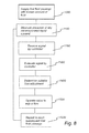
- the following example will be based on a system comprising an evaporator 54 with one fluid passage 3a only which is supplied with the first fluid via an injector arrangement 25a comprising one injector 23a and one valve 22a. Further, the example is based on the assumption that the system has been operated during a period of time in a predetermined operation duty.
- the first fluid passage 3a is supplied with a known flow amount of the first fluid 1000.
- This known flow amount is assumed to correspond to an amount to be fully evaporated before leaving the first fluid passage 3a or shortly thereafter, i.e. it is assumed to correspond to that required to meet the decided set-point superheating temperature TshT.
- the sensor arrangement 28 downstream the outlet of the evaporator measures the presence of any liquid content 1100.
- the signal generated by the sensor arrangement 28 is received 1200 by a controller 57.
- the controller may be a PID regulator.
- the controller evaluates 1300 the received signal.
- the signal may be a digital signal: 1 - no liquid content detected; 0 - liquid content detected. More precisely, a signal having the value 1 indicates that the evaporated fluid has a measured temperature Tm corresponding to or being above the superheating temperature Tsh. Likewise, a signal having the value 0 indicates that the evaporated fluid has a temperature being below the superheating temperature.
- the two sensors 30a, 30b may indicate different values. If both temperature sensors 30a, 30b indicate 0, this means that the gas is has a liquid content, and the evaporation is insufficient. The amount of first fluid supplied to the evaluated fluid passage 3a must be restricted since the system is flooded.
- the temperature sensor 30a closest to the evaporator indicates 0 but the second sensor 30b, downstream thereof, indicates 1, this means that the evaluated fluid passage 3a is operating well since all supplied fluid is fully evaporated. It is also a good indicator of that if any flow adjustment should be made, the supplied flow should rather be reduced than increased to avoid flooding.
- the controller 57 may be arranged to, when receiving a signal indicating presence or no presence of any liquid content, determine 1400 a suitable adjustment of the flow of first fluid to be provided by the valve 22a in an individual injector arrangement 25a to the evaluated fluid passage 3a in order to optimize its performance. Based on this determined adjustment, the valve 22a may be operated 1500 to adjust the flow accordingly.
- the controller 57 may use different ranges of adjustments depending on a determined likeliness of the closeness to the superheating temperature.
- the flow supplied to an evaluated first passage 3a is adjusted before continuing with evaluating the subsequent fluid passage 3b.
- the controller is arranged to store the determined value of the required flow adjustment to each evaluated flow passage 3a, 3b in its memory. Once all flow passages 3a, 3b have been evaluated in the same manner, the controller 57 may instruct each individual valve 22a, 22b to make the required flow adjustment. Thus, all flow adjustments may be made at the same time.
- each first fluid passage 3a, 3b may be operated in an optimized manner based on its inherent condition, such as position within the plate package P or dimensional differences between the two heat exchanger plates A, B delimiting the first fluid passage 3.
- This allows the operation of the evaporator 54 as a whole to be optimized. Also, this allows a better degree of utilization of the complete system in which the evaporator is forming part.
- the controller 57 may store all received measurement data in a memory for use when determining flow adjustments. Further, the controller 57 may be arranged to use the history from such stored information when determining required flow adjustments.
- the flow is directed essentially in a direction in parallel with the flow direction through the evaporator. Thereby any undue re-direction of the fluid flow may be avoided.
- the evaporator being a plate heat exchanger this means in parallel with the general plane of the first and the second heat exchanger plates.
- the injectors of the injector arrangements are disclosed as being arranged in through holes extending from the exterior of the plate package into the individual fluid passages. It is to be understood that this is only one possible embodiment.
- the injectors of the injector arrangements may extend into any inlet port or the like depending on the design of the evaporator. This may by way of example be made by an insert along an inlet channel.
- the invention has generally been described based on a plate heat exchanger having first and second plate interspaces and four port holes allowing a flow of two fluids. It is to be understood that the invention is applicable also for plate heat exchangers having different configurations in terms of the number of plate interspaces, the number of port holes and the number of fluids to be handled.
- controller may be used for other purposes as well, such as control of the refrigerant circuit as such.
Landscapes
- Engineering & Computer Science (AREA)
- Physics & Mathematics (AREA)
- Mechanical Engineering (AREA)
- Thermal Sciences (AREA)
- General Engineering & Computer Science (AREA)
- Heat-Exchange Devices With Radiators And Conduit Assemblies (AREA)
- Air Conditioning Control Device (AREA)
- Filling Or Discharging Of Gas Storage Vessels (AREA)
Abstract
Description
- The present invention refers generally to a system for dynamic control of the operation of an evaporator. Further, the invention refers to a method for dynamic control of the operation of an evaporator.
- The present invention refers generally to a system comprising an evaporator and in particular to an evaporator in the form of a plate heat exchanger. Generally, an evaporator is designed for evaporation of a fluid, such as a cooling agent, for various applications, such as air conditioning, cooling systems, heat pump systems, etc. Thus the evaporator may be used in a two-phase system handling a fluid in a liquid form as well as in a gaseous form.
- In case of the evaporator being a plate heat exchanger, this may by way of example include a plate package, which includes a number of first and second heat exchanger plates. The plates are permanently joined to each other and arranged side by side in such a way that a first plate interspace, forming a first fluid passage, is formed between each pair of adjacent first heat exchanger plates and second heat exchanger plates, and a second plate interspace, forming a second fluid passage, between each pair of adjacent second heat exchanger plates and first heat exchanger plates. The first plate interspaces and the second plate interspaces are separated from each other and provided side by side in an alternating order in the plate package. Substantially each heat exchanger plate has at least a first porthole and a second porthole, wherein the first portholes form a first inlet channel to the first plate interspaces and the second portholes form a first outlet channel from the first plate interspaces and wherein the plate package includes a separate space for each of said first plate interspaces, which space is closed to the second plate interspaces.
- In this general prior art plate heat exchanger to be used in a two-phase system a first fluid, such as a cooling agent, is introduced into the valve in liquid form but expands when leaving the valve due to the pressure drop into a partly evaporated fluid at one end of the first inlet channel, i.e. the first port hole, for further distribution along the first inlet channel and further into each of the individual first plate interspaces during evaporation into a gaseous form. There is always a risk that the energy content of the supplied fluid is too high, whereby a part of the flow supplied to the inlet channel via its inlet port will meet the rear end of the inlet channel and be reflected thereby in the opposite direction. Thereby the flow in the inlet channel is very chaotic and hard to predict and control.
- Further, the pressure drop of the cooling agent may increase with the distance from the inlet to the first inlet channel, whereby the distribution of the first fluid between the individual plate interspaces will be affected. It is known that the angular flow change that the droplets of the first fluid must undergo when entering the individual plate interspaces from the first inlet channel contributes to an uneven distribution. Yet another influencing parameter is dimensional differences between the individual first plate interspaces, resulting in that each first plate interspace has its unique efficiency. It is also to be known that the operation and performance of an individual first plate interspace depends on its position in a plate package. The outer most first plate interspaces on each side of the plate package tend to behave different than those in the middle of the plate package.
- As a result of this it is very hard, or even impossible, to optimize the operation and efficiency of an evaporator as a whole, ensuring that all fluid supplied to the evaporator is fully evaporated before leaving the outlet of the evaporator and especially before reaching the inlet of a compressor to be arranged downstream of the outlet of the evaporator. In fact it is sufficient that there is one malfunctioning first plate interspace for insufficient evaporation of the evaporator as a whole to occur. By way of example, if one single first plate interspace is flooded, i.e. is incapable of evaporating the complete amount of fluid supplied thereto, droplets will occur downstream the outlet of the evaporator. Generally, by fully evaporated means that the evaporated fluid must have reached the superheating temperature whereby the evaporated fluid comprises dry gaseous fluid only, i.e. the evaporated fluid should have a temperature being higher than the saturation temperature at a prevailing pressure.
- The purpose of operating the evaporator as close to a superheating set-point temperature as possible no matter operation duty is of importance to get as high utilization factor as possible. Thus, it is of economic importance. Further, it has an influence to other components cooperating with the evaporator, such as a compressor, since compressors normally are sensitive to liquid content. Any droplets remaining in the evaporated fluid when reaching the inlet of the compressor may damage the same. Also, there is an economical interest of operating the evaporator as close to the superheating temperature as possible since once the fluid has reached the superheating temperature the fluid is completely dry and there is no gain in increasing the temperature additionally. The superheating temperature set-point above is determined by the system manufacturer to incorporate a certain wanted safety margin against the risk of receiving liquid into the compressor. The problems discussed above get more pronounced when the load of the evaporator is changed. This may by way of example be the case when changing the operation duty of an air conditioning system, from one temperature to another, meaning that the amount of fluid to be supplied to the evaporator is changed.
- Documents
EP2156112B1 andWO2008151639A1 provide a method for controlling a refrigerant distribution among at least two evaporators in such a manner that the refrigeration capacity of air-heated evaporators is utilized to the greatest possible extent. This is made by monitoring a superheat of refrigerant at a common outlet of the evaporators. Further, this is made by altering a mass flow of refrigerant through a selected evaporator while keeping the total mass flow of refrigerant through all the evaporators substantially constant. The flow is controlled by one single valve being an expansion valve. Thus, the two documents provide a solution to controlling the operation of a plurality of air-heated evaporators, in which method each evaporator is evaluated as a complete unit and in which method each unit is controlled in view of additional evaporators arranged in the same circuit. - Generally, the efficiency of evaporators and especially plate heat exchangers at part load is a raising issue. More focus is put on how the evaporator performs at different operation duties instead of being measured at only one operation duty. By way of example, laboratory scale trials have shown that an air-conditioning system can save 4-10 % of its energy consumption just by improved evaporator function at part load for a given brazed plate heat exchanger. Further, an evaporator system is typically only operating at full capacity for 3 % of the time, while most evaporators are designed and tuned for a full capacity operation.
- The object of the present invention is to provide an improved evaporator system remedying the problems mentioned above. Especially it is aimed at an evaporator and a method which allows a better control and distribution of the supply of the first fluid, such as the cooling agent, between the fluid passages to thereby improve its efficiency of the plate heat exchanger no matter running condition.
- This object is achieved by a system for dynamic control of the operation of an evaporator, the system comprising an evaporator, a plurality of injector arrangements, a sensor arrangement and a controller, wherein the evaporator comprises an outlet, a plurality of fluid passages and at least one inlet for the supply of a fluid to the outlet via the plurality of fluid passages during evaporation of the fluid, each injector arrangement comprises at least one injector and at least one valve, and each injector arrangement being arranged to supply a flow of the fluid to at least one of the fluid passages via the at least one inlet of the evaporator, the sensor arrangement is arranged to measure temperature and pressure of the evaporated fluid, or the presence of any liquid content in the evaporated fluid , and the controller is arranged to communicate with the valves of the injector arrangements for the valves to control, based on information received from the sensor arrangement, the amount of fluid to be supplied by each injector arrangement to each fluid passage in the evaporator in order for the evaporator to operate towards a set-point superheating value.
- By a system having this configuration, the operation of each fluid passage or a smaller amount of fluid passages may to be monitored, whereby the contribution from each individual fluid passage to the overall performance of the evaporator may be adjusted in order for the evaporator to operate towards a set-point superheating value.
- By the term "liquid content" is in the following defined as fluid being in a liquid phase or a mixed liquid/gaseous phase. It may by way of example be in the form of droplets.
- Provided the sensor arrangement is arranged to measure temperature and pressure, the set-point superheating value may by way of example be decided by the manufacturer of the system to safeguard against the risk of having liquid entering the compressor. In case the sensor arrangement is arranged to instead measure the presence of any liquid content in the evaporated fluid, the set-point superheating value may be handled in a "digital" manner, wherein presence of any liquid content is an indicator of the amount of fluid supplied to the evaluated fluid passage is too high for a complete evaporation, or alternatively, no presence of any liquid content is an indicator of the amount of fluid supplied to the fluid passage being insufficient and may be increased.
- By operating the inventive system continuously, to each fluid passage one after the other, the operation of the evaporator may be iteratively optimized in view of a desired operation duty. This allows the size/dimensions of the evaporator to be optimized. Also, not at least, the energy consumption required to operate a system comprising the evaporator as one component may be reduced. It also allows the possibility to use a smaller compressor to be arranged downstream of the evaporator.
- Each injector in an injector arrangement may be arranged to communicate with one valve, or alternatively, a plurality of injectors in an injector arrangement may be arranged to communicate with one valve. Accordingly, one and the same valve may control the amount of fluid supplied to each fluid passage based on the instructions received from the controller.
- Each injector arrangement may be arranged to communicate with one fluid passage, or alternatively, each injector arrangement may be arranged to communicate with at least two fluid passages. This allows the operation of each fluid passage or a smaller number of fluid passages to be controlled, whereby the contribution from each individual fluid passage to the overall performance of the evaporator may be adjusted and optimized.
- The sensor arrangement may be arranged in a tube system connecting the outlet of the evaporator with an inlet of a compressor. Thereby the inherent temperature of the tube system may be used to further contribute to the evaporation of any remaining liquid content in the fluid after the outlet of the evaporator.
- The controller may be a PID regulator. A PID regulator is a regulator well known in the field of automatic control engineering. The PID regulator may be used to relatively fast find the set-point without causing any self-oscillation of the system.
- The evaporator may be a plate heat exchanger. The plate heat exchanger may by way of example be a plate heat exchanger having first and second fluid passages and four port holes allowing a flow of two fluids. It is to be understood that the invention is equally applicable to plate heat exchangers having different configurations in terms of the number of fluid passages, the number of port holes and the number of fluids to be handled.
- The sensor arrangement may comprise at least one temperature sensor and at least one pressure sensor. The two sensors must not have the same position.
- Alternatively, in case the sensor arrangement is arranged to measure the presence of any liquid content in the evaporated fluid, the sensor arrangement may be at least one temperature sensor. The temperature sensor may be used for determining a tendency of decreasing temperature as seen over a measuring period or be used for determining an unstable temperature as seen over a measuring period. Both a tendency of decreasing temperature and an unstable temperature may be used as input to the controller to establish the presence of any liquid content in the evaporated fluid since the liquid content, i.e. a fluid flow being in liquid phase or in a mixed liquid/gaseous phase will indicate a lower temperature on the temperature sensor than a fully evaporated, dry gaseous fluid flow.
- According to another aspect, the invention relates to a method for dynamic control of the operation of an evaporator, the evaporator comprising at least one inlet, a plurality of fluid passages and an outlet, and the evaporator being included in a system further comprising a sensor arrangement, a controller and a plurality of injector arrangements, each injector arrangement comprising at least one injector and at least one valve, whereby the method comprises the steps of:
- a) supplying via an inlet of the evaporator a pre-determined amount of fluid by a first injector arrangement to a first fluid passage for evaporation of the fluid during its passage to the outlet of the evaporator,
- b) measuring by the sensor arrangement temperature and pressure of the evaporated fluid or the presence of any liquid content in the evaporated fluid,
- c) determining, by the controller, the difference between a set-point super heating value and the measured values of the temperature and the pressure of the evaporated fluid, or the presence of any liquid content in the evaporated fluid, resulting from the pre-determined amount of supplied fluid,
- d) determining, by the controller, an adjusted amount of fluid to be supplied by the valve of the first injector arrangement to the first fluid passage required to reach the set-point superheating value, and
- e) continuously repeating steps a) - d) to each consecutive injector arrangement and each fluid passage of the evaporator for the purpose of providing a continuous control of the operation of the evaporator in order for the evaporator to operate towards a set-point superheating value.
- By the method, the operation of each fluid passage or a smaller number of fluid passages may be monitored, whereby the contribution from each individual fluid passage to the overall performance of the evaporator may be continuously adjusted in order for the evaporator to operate towards a set-point superheating value with an optimized flow through each fluid passage. The optimization may be a maximizing of the amount of supplied fluid.
- Provided the sensor arrangement is arranged to measure temperature and pressure, the set-point superheating value may by way of example be the superheating temperature for the specific fluid used in the system.
- Alternatively, the superheating value may be the calculated superheating temperature for the specific fluid used in the system as adjusted with a pre-determined safety margin. In case the sensor arrangement is arranged to instead measure the presence of any liquid content in the evaporator, the set-point superheating value may be handled in a "digital" manner, wherein presence of any liquid content is an indicator of the amount of fluid supplied to the evaluated fluid passage being too high for a complete evaporation, or alternatively, no presence of any liquid content is an indicator of the amount of fluid supplied to the fluid passage being insufficient and may be increased.
- Further, by the method, continuously monitoring and adjusting the operation of the individual fluid passages or groups of fluid passages, the operation of the evaporator may be iteratively optimized in view of a desired operation duty. More precisely, by repeating the method steps to each consecutive injector arrangement and to each fluid passage any unbalance in the evaporator as a whole between the pluralities of fluid passages may be taken care of. This allows the size/dimensions of the evaporator to be reduced which in turn allows a cost reduction. Not at least, the energy consumption required to operate a system comprising the evaporator as one component may be reduced.
- The system may be operated during a period of time in a predetermined operation duty before initiating step a). In case of the
evaporator 54 forming part of an air-conditioning system, this may by way of example be an operation duty corresponding to an office during normal working hour, such as 20°C. Thereby all components of the system will have a chance to be conditioned before initiating the optimization process. - In case the sensor arrangement is arranged to measure temperature and pressure of the evaporated fluid, the method may further comprise the steps of:
- converting, by the controller, the measured pressure Pm into a saturation temperature Ts, determining the actual superheating temperature difference TshA, prevailing at the specific point of time when the temperature and pressure was measured, by comparing the measured temperature Tm with the saturation temperature Ts;
- determining the temperature difference ΔT between a set-point superheating value being a set-point superheating temperature TshT and the actual superheating temperature difference TshA; and determining, based on the temperature difference, the need for any adjustment of the amount of fluid supplied by the valve of the first injector arrangement to the first fluid passage, and instructing the valve of the first injector arrangement to adjust the amount of fluid to be supplied by the first injector arrangement to the first fluid passage accordingly.
- The conversion of the measured pressure into a saturation temperature may be made by the controller using pre-programmed information specific for the fluid used in the evaporator. Such information is readily available in graphs or tables plotting vapor pressure versus temperature for a specific fluid.
- In case the sensor arrangement is a humidity sensor, the method may further comprise the steps of, provided the sensor generates a signal received by the controller indicating presence of any liquid content in the evaporated fluid, instructing the valve of the first injector arrangement to reduce the amount of fluid supplied to the first fluid passage, or provided the sensor generates a signal received by the controller indicating no presence of any liquid content in the evaporated fluid, instructing the valve of the first injector arrangement to increase the amount of fluid supplied to the first fluid passage.
- This may be made by the humidity sensor being a temperature sensor determining a tendency of decreasing temperature as seen over a measuring period or determining an unstable temperature as seen over a measuring period. Both a tendency of decreasing temperature and an unstable temperature may be used as input to the controller to establish the presence of any liquid content in the evaporated fluid since a liquid phase or a mixed liquid/gaseous phase fluid will have a lower temperature than a fully evaporated, dry gaseous fluid flow.
- In case the sensor arrangement comprises at least two humidity sensors, the method may further comprise the step of comparing the signals received by the controller from the at least two sensors indicating presence or no presence of any liquid content in the evaporated fluid in order to determine if to instruct the valve of the first injector arrangement to increase, decrease or maintain the supplied amount of fluid to the first fluid passage, and instructing the valve of the first injector arrangement to adjust the amount of fluid to be supplied by the first injector arrangement to the first fluid passage accordingly.
- Again, this may be made by using humidity sensors in the form of temperature sensors, determining a tendency of decreasing temperature as seen over a measuring period or determining an unstable temperature as seen over a measuring period. By comparing the signals received by the controller from the at least two sensors it is possible, by the controller to determine any contribution from a tube system connecting the outlet of the evaporator with the inlet of a compressor to the evaporation. The tube system is typically hot, whereby any contact between any remaining liquid content in the evaporated fluid downstream of the outlet of the evaporator may cause an evaporation when such liquid content comes into contact with the tube system on its way to a compressor downstream thereof.
- The method may further comprise, before continuing to step e), the step of communicating the determined adjusted amount of fluid to the valve of the first injector arrangement and adjusting the valve to supply an adjusted amount of fluid.
- Thus, according to this embodiment, the operation of a first fluid passage is evaluated and its fluid supply is adjusted before continuing evaluating and adjusting the operation of the subsequent fluid passages.
- Alternatively, the method may further comprise a step of communicating the determined adjusted amount of fluid to the valves of each injector arrangement and adjusting the valves to supply an adjusted amount of fluid to all fluid passages of the evaporator. Thus, according to this embodiment, the operation of each fluid passage is evaluated before all valves and their supply of fluid is adjusted.
- When the operation of the evaporator has been operated to an operation duty meeting the set-point superheating value, the method may further comprise the step of adjusting the set-point superheating value before repeating the method steps for the purpose of anew providing a continuous control of the operation of the evaporator in order for the evaporator to operate towards the adjusted set-point superheating value. According to this embodiment, it is made possible to continuously refine the operation of the evaporator and its individual first fluid passages.
- Embodiments of the invention will now be described, by way of example, with reference to the accompanying schematic drawings, in which
-
Fig. 1 schematically illustrates a prior art refrigeration circuit being a mechanical vapor compression system. -
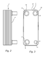
Fig. 2 discloses schematically a side view of a typical plate heat exchanger. -
Fig. 3 discloses schematically a front view of the plate heat exchanger ofFig. 1 . -
Fig. 4 discloses schematically a cross section along an edge of a prior art plate heat exchanger. -
Fig. 5 discloses a refrigeration circuit relating to the inventive system. -
Fig. 6 discloses schematically a cross section along an edge of a plate heat exchanger applying the inventive system. -
Fig. 7 discloses the steps of the inventive method using sensors for detecting temperature and pressure. -
Fig. 8 discloses the steps of the inventive method using sensors for detecting any liquid content. - A
heat exchanger 1 may typically be included as an evaporator in a refrigeration circuit. A prior art refrigeration system, seeFig. 1 , being a mechanical vapor compression system, typically comprises acompressor 51, acondenser 52, anexpansion valve 53 and anevaporator 54 . The circuit may further comprise apressure sensor 55 and atemperature sensor 56 arranged between the outlet of the evaporator and the inlet of the compressor. The refrigeration circle of such system starts when a cooling agent enters thecompressor 51 in gaseous form with a low pressure and with a low temperature. The cooling agent is compressed by thecompressor 51 to a high pressure and high temperature gaseous state before entering thecondenser 52. Thecondenser 52 precipitates the high pressure and high temperature gas to a high temperature liquid by transferring heat to a lower temperature medium, such as water or air. The high temperature liquid then enters theexpansion valve 53 where the expansion valve allows a portion of the cooling agent to enter theevaporator 54. Theexpansion valve 53 has the function of expanding the cooling agent from the high to the low pressure side, and to fine tuning the flow. In order for the higher temperature to cool, the flow into the evaporator must be limited to keep the pressure low and allow expansion back into the gaseous form. Theexpansion valve 53 may be operated by acontroller 57 based on signals received from thepressure sensor 55 and thetemperature sensor 56. The information may be used to indicate the overall operation of theevaporator 54 based on a so called super heating temperature being indicative of any liquid content remaining in the fluid after leaving theevaporator 54. - Now turning to
Figs. 2 to 4 a typical evaporator in the form of aplate heat exchanger 1 is disclosed. It is to be understood that theheat exchanger 1 may be of any type, such as a plate heat exchanger, a pipe and shell heat exchanger, a spiral heat exchanger etc. The invention will however in the following be discussed as applied to aplate heat exchanger 1, although the invention is not to be limited thereto. - The
plate heat exchanger 1 includes a plate package P, which is formed by a number of heat exchanger plates A, B, which are provided side by side. The heat exchanger plates include in the embodiment disclosed two different plates, which in the following are called first and second heat exchanger plates A and B. The heat exchanger plates A, B are provided side by side in such a manner that afirst fluid passage 3 is formed between each pair of adjacent first heat exchanger plates A and second heat exchanger plates B, and asecond fluid passage 4 is formed between each pair of adjacent second heat exchanger plates B and first heat exchanger plates A. The plate package P further includes anupper end plate 6 and alower end plate 7 provided on a respective side of the plate package P. - As appears from especially
Fig.3 and4 , substantially each heat exchanger plate A, B has fourportholes 8. Thefirst portholes 8 form afirst inlet channel 9 to the firstfluid passages 3, which extends through substantially the whole plate package P, i. e. all plates A, B and theupper end plate 6. Thesecond portholes 8 form afirst outlet channel 10 from the firstfluid passages 3, which also extends through substantially the whole plate package P, i.e. all plates A, B and theupper end plate 6. Thethird portholes 8 form asecond inlet channel 11 to the secondfluid passages 4, and thefourth portholes 8 form asecond outlet channel 12 from the secondfluid passages 4. Also these twochannels upper end plate 6. - Now turning to
Fig. 5 a first embodiment of the inventive system will be discussed. The system comprises anevaporator 54 in the form of a plate heat exchanger. Theoutlet 13 of theevaporator 54 is connected to theinlet 14 of acompressor 51 via atube system 15. Further, theoutlet 16 of thecompressor 51 is via anothertube system 17 connected to theinlet 18 of acondenser 52. Yet further, theoutlet 19 of thecondenser 52 is connected to a plurality ofinjector arrangements injector arrangement valve injector injector arrangements first fluid passage evaporator 54. Thus, a closed circulation system is provided. - The plurality of
injector arrangements Fig. 6 are arranged to supply a flow of a first fluid viainlets fluid passages evaporator 54 via itsoutlet 13. Eachinlet arrangement 25a; 25b comprises oneinjector 23a; 23b and onevalve 22a; 22b. Thevalves 22a; 22b are preferably positioned exterior of theevaporator 54, whereas theinjectors 23a; 23b withnozzles evaporator 54 via theinlets 26a; 26b. - The
inlets 26a; 26b are in the form of through holes having an extension from the exterior of the plate package P to the interior of the plate package and more precisely into the individual firstfluid passages 3a; 3b. The through holes may be formed by plastic reshaping, by cutting or by drilling. The term plastic reshaping refers to a non-cutting plastic reshaping such as thermal drilling. The cutting or drilling may be made by a cutting tool. It may also be made by laser or plasma cutting. A cross section of the inlet area of an evaporator possible to be used in the inventive system is disclosed inFig. 6 . Theinlet channel 9 of the embodiment ofFig. 4 has been replaced by eachfirst fluid passage 3 receiving aninjector arrangement 25a; 25b via theinlets - It is to be understood that each
inlet arrangement 25a; 25b may comprise a plurality ofinjectors 23a; 23b, wherein the plurality of injectors are communicating with one valve. - In its most simple form the
nozzles 27a; 27b may be omitted whereby eachinjector 23a; 23b may be formed by a through hole (not disclosed) or a pipe (not disclosed) for distribution of the first fluid. - It is to be understood that the number of
injectors 23a; 23b may be lower than the number of firstfluid passages 3. Thereby eachinjector 23a; 23b may be arranged to supply its flow of the first fluid to more than one of the firstfluid passages 3. This may be made possible by each injector being arranged in a through hole having a diameter extending across two or more fluid passages, whereby one and the same injector may supply fluid to more than one fluid passage. - The inventive system further comprises a
sensor arrangement 28. In the disclosed embodiment thesensor arrangement 28 comprises one pressure sensor 29 and onetemperature sensor 30. Thesensor arrangement 28 may be arranged in thetube system 15 connecting theoutlet 13 of theevaporator 54 with theinlet 14 of thecompressor 51 and more precisely in or after theoutlet 13 of the evaporator but before theinlet 14 of thecompressor 51. The twosensors 29, 30 must not have the same position within the system. It may also be possible to arrange the sensor arrangement or a part thereof in the outlet channel (not disclosed) of theevaporator 54. - The pressure sensor 29 is preferably arranged after the
outlet 13 of theevaporator 54 in a more or less straight section of thetube system 15 connecting theevaporator 54 with thecompressor 51. Depending on the configuration of thetube system 15 it may, as a rule of thumb, be preferred, that the pressure sensor 29 is arranged on a distance after a tube bend corresponding to at least ten times the inner diameter of the tube, and on a distance before a tube bend corresponding to more than five times the inner diameter of the tube. - The pressure sensor 29 is arranged to measure the pressure of the evaporated first fluid, in the following identified as the measured pressure Pm.
- The pressure sensor 29 may by way of example be a 4-20 mA pressure sensor with a range from 0-25 bar.
- The
temperature sensor 30 is preferably arranged in thetube system 15 after a tube bend. It is preferred that thetemperature sensor 30 is arranged closer to theinlet 14 of thecompressor 51 than to theoutlet 13 of theevaporator 54. By positioning thetemperature sensor 30 after a tube bend it is more likely that any remaining liquid content in the evaporated fluid is evaporated while meeting the walls of the tube bend and thereby being forced to change its flow direction. There is also an evaporation taking place by the remaining liquid contents absorbing heat from the surrounding superheated fluid flow. - The
temperature sensor 30 may be a standard temperature sensor measuring the temperature, in the flowing identified as the measured temperature Tm. - The system further comprises a
controller 57 arranged to communicate with thesensor arrangement 28 and theindividual valves 22a; 22b of theinjector arrangements 25a; 25b. Thecontroller 57 may by way of example be a PID regulator. - The measured values regarding pressure Pm and temperature Tm are communicated to the
controller 57 which is arranged to regulate the system based on a so called superheating temperature. - The superheating temperature, being a physical parameter well known in the art, is defined as the temperature difference between the present temperature and the saturated temperature at a prevailing pressure, i.e. there is not any liquid content remaining in the fluid. The superheating temperature difference is unique for a given fluid and for a given temperature and pressure and the super heating temperature may be found in graphs or tables.
- Generally, the closer the measured temperature Tm comes to the saturation temperature, the more efficient the system becomes. That is, the amount of fluid supplied to the evaporator is completely evaporated and not unnecessary superheated.
- However, the closer the measured temperature Tm comes to the saturation temperature, the closer it comes to flooding the system with non-evaporated fluid, i.e. the evaporator is incapable of evaporating the supplied amount of fluid. Solely for illustrative purpose, the superheating temperature may be regarded as being digital - either there is a complete evaporation without any liquid content, or there is an incomplete evaporation with liquid content contained in the gaseous flow downstream the evaporator.
- In order to optimize the operation of an evaporator it is desired to have as low superheating temperature difference as possible. However, since a compressor is sensitive to liquid content and may be damaged thereby, its common praxis to use a safety margin of some degrees when designing an evaporation system. Typically, a normal safety margin for a prior art evaporator is 5° K, i.e. the superheating temperature difference is 5° K. However, it is to be understood that another value of the safety margin may be elected. In its most simple form, the safety margin is to be regarded as a constant decided by the intended use of the evaporator. It is however to be understood that there is also a desire to use as low safety margin as possible since there is an economical interest of operating the evaporator as close to the saturation temperature as possible. During the operation of the inventive system this constant will be used as a set-point superheating temperature TshT, i.e. a target value, towards which the operation of the evaporator 554 will be dynamically controlled. This will be made by optimizing the contribution from each
first fluid passage evaporator 54. More precisely, the underlying inventive concept is to control, by using onevalve injector fluid passage fluid passage fluid passage - In the following the general principle for establishing the operation condition, i.e. superheating or not, will be described with reference to
Fig. 7 . To facilitate the understanding, the following example will be based on a system comprising anevaporator 54 with onefirst fluid passage 3a only which is supplied with the first fluid via aninjector arrangement 25a comprising oneinjector 23a and onevalve 22a. Further, the example is based on the assumption that the system has been operated during a period of time in a predetermined operation duty. In case of theevaporator 54 forming part of an air-conditioning system, this may by way of example be an operation duty corresponding to an office during normal working hour, such as 20°C. - The first fluid passage is supplied 100 with a known flow amount of the first fluid. This known flow amount is assumed to correspond to an amount to be fully evaporated before leaving the first fluid passage or shortly thereafter, i.e. it is assumed to correspond to that required to meet the decided set-point superheating temperature TshT.
- The sensor arrangement downstream the outlet of the
evaporator measures 200 the prevailing temperature Tm and the pressure Pm. These values are received by thecontroller 57. - The
controller 57converts 300 the measured pressure Pm into a saturation temperature Ts. The saturation temperature Ts is specific for a predetermined cooling agent, i.e. the first fluid used in the system. By way of example, provided the first fluid used is a cooling agent known as R410A, the saturation temperature Ts may be calculated by using the following formula specific for R410A
- The formula given above reflects the curve of a diagram wherein the saturation temperature is plotted versus a pressure. It is to be understood that the saturation pressure may be calculated in a number of ways, depending on e.g. different interpolation methods, different levels of accuracy etc. Further, it is to be understood that only a limited section of the curve may be evaluated. It is further to be understood that instead of calculating the saturation temperature Ts, the controller may be set to get the corresponding value by using a table containing the corresponding values.
- The
controller 57 establishes 400 the actual superheating temperature difference TshA prevailing at the specific point of time when the measuring was made by comparing the measured temperature Tm with the calculated saturation temperature Ts, by using the formula:
- Thus, the
controller 57 has now established the prevailing, actual superheating difference TshA and it knows the set-point superheating temperature TshT. The next step is to decide thetemperature difference ΔT 500 between the set-point superheating temperature TshT and the actual superheating temperature difference TshA by using the formula:
- Based on the value of the temperature difference ΔT, the prevailing performance of the
fluid passage 3a is evaluated 600. If ΔT is negative, the fluid passage is fed with an insufficient amount of fluid, whereby the controller may instruct the valve to increase the amount of fluid supplied to the fluid passage. If on the other hand ΔT is positive, the fluid passage is fed with too much fluid, whereby the controller may instruct the valve to decrease the amount of fluid supplied to the fluid passage. If ΔT = 0, the performance of the fluid passage is optimized and no changes in the supplied flow amount are required. - It is to be known that there is no correlation between ΔT and the required amount of first fluid to be supplied. Non-limiting examples of influencing parameters are the design of the
fluid passage 3a, the size of thefluid passage 3a and dimensional variations inside thefluid passage 3a. As a general rule of thumb, a large ΔT is indicative of the possibility of a large adjustment, whereas a small ΔT is indicative of the possibility of a small adjustment. The controller may by way of example be programmed to use different percental corrections depending on the absolute value of the temperature difference. - Based on the determined adjustment, the
valve 22a is operated 700 to adjust the flow accordingly. - The process above is descried based on an evaporator 5 comprising one
fluid passage 3a only. However, it is to be understood that for an evaporator 54normally comprising a plurality of firstfluid passages consecutive fluid passage 3b and itsrelated injector arrangement 25b to the same procedure to thereby gradually step-by-step optimize the performance of theevaporator 54 as a whole and also maximizing the fluid amount handled by the evaporator as a whole. - It is to be understood that while evaluating one
fluid passage 3a, the remainingfluid passages 3b and theirrelated injector arrangements 25b may be operated in a known manner in order to be able to evaluate the performance of the evaluated fluid passage. After finishing thecomplete evaporator 54, the process may be started all over again with thefirst fluid passage 3a. - It is also to be understood that an evaporation system as such is a rather slow system since the components, i.e. the
evaporator 54, thecompressor 51, thecondenser 52 and the ambient water/liquid/air to be cooled, each have their own influence to the overall performance of the system. Thus, for any changes in flow amounts to actually take effect, no rapid changes must be made. - In the example given above the flow supplied to a
first fluid passage 3a evaluated is adjusted before continuing with evaluation thesubsequent fluid passage 3b. In one alternative embodiment thecontroller 57 is arranged to store the determined value of the required flow adjustment to each evaluatedflow passage flow passages controller 57 may instruct eachindividual valve - As an alternative to the
sensor arrangement 28 comprising a pressure sensor 29 andtemperature sensor 30, thesensor arrangement 28 may comprise at least one sensor arranged for detecting presence of any liquid content. The liquid content may be in liquid form or in mixed liquid/gaseous phase. One example of a suitable sensor is atemperature sensor 30. - The presence of any liquid content proves that the evaporation is insufficient and that the flow of first fluid should be reduced. As discussed above, the closer the superheating temperature, the closer to flooding the system with non-evaporated fluid. Since the superheating temperature may be regarded as being digital - there is either a complete evaporation with dry gas only, or there is an incomplete evaporation with a liquid content in the fluid downstream the evaporator.
- In case the
sensor arrangement 28 comprises a sensor for detecting presence of any liquid content in the evaporated fluid, such sensor/sensors should preferably be arranged in the tube system connecting the outlet of the evaporator with the inlet of the compressor. Thus, the position may be the same as in the system described above relating toFig. 5 . The only difference is that the pressure sensor 29 may be omitted. It is preferred for the sensor/sensors adapted to detect presence of any liquid content, e.g. atemperature sensor 30 is arranged in a position closer to theinlet 14 of thecompressor 51 than to theoutlet 13 of theevaporator 54. Further, it is preferred forsuch temperature sensor 30 to be positioned in thetube system 15 after at least one tube bend in order to allow at least some remaining liquid content to evaporate during contact with the inner walls of thetube system 15 or while coming into contact with the hot surrounding gaseous fluid flow. Thus, if measuring directly after theoutlet 13 of theevaporator 54, a low amount of liquid content may be detected, whereas if measuring further downstream, such liquid content may have evaporated along the tube system whereby the gaseous flow reaching the compressor is dry. Thus, it is preferred that asensor arrangement 28 based on detection of presence of any liquid content comprises at least twosensors - In the following the general principle for establishing the operation condition, i.e. superheating for a system using a sensor arrangement based on detection of any liquid content will be described with reference to
Fig. 8 . The evaporation system as such has the same general design as that previously described with reference toFig. 6 whereby reference is made thereto. - To facilitate the understanding, the following example will be based on a system comprising an
evaporator 54 with onefluid passage 3a only which is supplied with the first fluid via aninjector arrangement 25a comprising oneinjector 23a and onevalve 22a. Further, the example is based on the assumption that the system has been operated during a period of time in a predetermined operation duty. - The
first fluid passage 3a is supplied with a known flow amount of thefirst fluid 1000. This known flow amount is assumed to correspond to an amount to be fully evaporated before leaving thefirst fluid passage 3a or shortly thereafter, i.e. it is assumed to correspond to that required to meet the decided set-point superheating temperature TshT. - The
sensor arrangement 28 downstream the outlet of the evaporator measures the presence of anyliquid content 1100. The signal generated by thesensor arrangement 28 is received 1200 by acontroller 57. The controller may be a PID regulator. - The controller evaluates 1300 the received signal. In its most simple form the signal may be a digital signal: 1 - no liquid content detected; 0 - liquid content detected. More precisely, a signal having the
value 1 indicates that the evaporated fluid has a measured temperature Tm corresponding to or being above the superheating temperature Tsh. Likewise, a signal having the value 0 indicates that the evaporated fluid has a temperature being below the superheating temperature. - In case the
sensor arrangement 28 comprises twotemperature sensors tube system 15, the twosensors temperature sensors fluid passage 3a must be restricted since the system is flooded. - If the
temperature sensor 30a, closest to the evaporator indicates 0 but thesecond sensor 30b, downstream thereof, indicates 1, this means that the evaluatedfluid passage 3a is operating well since all supplied fluid is fully evaporated. It is also a good indicator of that if any flow adjustment should be made, the supplied flow should rather be reduced than increased to avoid flooding. - If both
sensors fluid passage 3a is evaporated. This means that the evaluatedfluid passage 3a is not working optimally and that it is possible to increase the amount of first fluid supplied to the evaluated fluid passage. - Although one 30 or two 30a, 30b temperature sensors are described above, it is to be understood that more than two temperature sensors may be arranged, the sensors working with the same principle.
- The
controller 57 may be arranged to, when receiving a signal indicating presence or no presence of any liquid content, determine 1400 a suitable adjustment of the flow of first fluid to be provided by thevalve 22a in anindividual injector arrangement 25a to the evaluatedfluid passage 3a in order to optimize its performance. Based on this determined adjustment, thevalve 22a may be operated 1500 to adjust the flow accordingly. - The
controller 57 may use different ranges of adjustments depending on a determined likeliness of the closeness to the superheating temperature. - The process above is descried based on an
evaporator 54 comprising onefluid passage 3a only. However, it is to be understood that for anevaporator 54 normally comprising a plurality of firstfluid passages 3a, the above descried cycle is repeated 1600 by subjecting eachconsecutive fluid passage 3b; 3c and itsrelated injector arrangement 25b, 25c to the same procedure to thereby gradually step-by-step optimize the performance of the evaporator as a whole. - It is to be understood that while evaluating one
fluid passage 3a, the remainingfluid passages 3b, 3c and theirrelated injector arrangements 25b, 25c should be operated in a known manner in order to be able to evaluate the performance of the evaluatedfluid passage 3a. After finishing the complete evaporator, the process may be started all over again with the first fluid passage. - In the example given above, the flow supplied to an evaluated
first passage 3a is adjusted before continuing with evaluating thesubsequent fluid passage 3b. In one alternative embodiment, the controller is arranged to store the determined value of the required flow adjustment to each evaluatedflow passage flow passages controller 57 may instruct eachindividual valve - Accordingly, by the invention, each
first fluid passage first fluid passage 3. This allows the operation of theevaporator 54 as a whole to be optimized. Also, this allows a better degree of utilization of the complete system in which the evaporator is forming part. - The
controller 57 may store all received measurement data in a memory for use when determining flow adjustments. Further, thecontroller 57 may be arranged to use the history from such stored information when determining required flow adjustments. - No matter how the injectors arrangements are arranged, it is preferred that the flow is directed essentially in a direction in parallel with the flow direction through the evaporator. Thereby any undue re-direction of the fluid flow may be avoided. In case of the evaporator being a plate heat exchanger this means in parallel with the general plane of the first and the second heat exchanger plates.
- The invention has been described as applied to an evaporator being a plate heat exchanger. However, it is to be understood that the invention is applicable no matter form of evaporator.
- The injectors of the injector arrangements are disclosed as being arranged in through holes extending from the exterior of the plate package into the individual fluid passages. It is to be understood that this is only one possible embodiment. By way of example, the injectors of the injector arrangements may extend into any inlet port or the like depending on the design of the evaporator. This may by way of example be made by an insert along an inlet channel.
- The invention has generally been described based on a plate heat exchanger having first and second plate interspaces and four port holes allowing a flow of two fluids. It is to be understood that the invention is applicable also for plate heat exchangers having different configurations in terms of the number of plate interspaces, the number of port holes and the number of fluids to be handled.
- It is to be understood that the controller may be used for other purposes as well, such as control of the refrigerant circuit as such.
- The invention is not limited to the embodiment disclosed but may be varied and modified within the scope of the following claims, which partly has been described above.
Claims (16)
- System for dynamic control of the operation of an evaporator, the system comprising an evaporator (54), a plurality of injector arrangements (25a, 25b), a sensor arrangement (28) and a controller (57), wherein
the evaporator (54) comprises an outlet (13), a plurality of fluid passages (3) and at least one inlet (26a, 26b) for the supply of a fluid to the outlet (13) via the plurality of fluid passages (3) during evaporation of the fluid,
each injector arrangement (25a, 25b) comprises at least one injector (23a, 23b) and at least one valve (22a, 22b), and each injector arrangement (25a, 25b) being arranged to supply a flow of the fluid to at least one of the fluid passages (3) via the at least one inlet (26a, 26b) of the evaporator (54),
the sensor arrangement (28) is arranged to measure temperature (Tm) and pressure (Pm) of the evaporated fluid, or the presence of any liquid content in the evaporated fluid , and
the controller (57) is arranged to communicate with the valves (22a, 22b) of the injector arrangements (25a, 25b) for the valves (22a, 22b) to control, based on information received from the sensor arrangement (28), the amount of fluid to be supplied by each injector arrangement (25a, 25b) to each fluid passage (3) in the evaporator (3) in order for the evaporator (54) to operate towards a set-point superheating value (TshT). - System according to claim 1, wherein each injector (23a, 23b) in an injector arrangement (25a, 25b) is arranged to communicate with one valve (22a, 22b), or wherein a plurality of injectors (23a, 23b) in an injector arrangement (25a, 25b) are arranged to communicate with one valve (22a, 22b).
- System according to claim 1, wherein each injector arrangement (25a, 25b) is arranged to communicate with one fluid passage (3), or wherein each injector arrangement (25a, 25b) is arranged to communicate with at least two fluid passages (3).
- System according to claim 1, wherein the sensor arrangement (28) is arranged in a tube system (15) connecting the outlet of the evaporator (13) with an inlet of a compressor (14).
- System according to claim 1, wherein the controller (57) is a PID regulator.
- System according to any of the previous claims, wherein the evaporator (54) is a plate heat exchanger (1).
- System according to claim 1, wherein the sensor arrangement (28) comprises at least one temperature sensor (30) and at least one pressure sensor (29).
- System according to claim 1, wherein the sensor arrangement (28) arranged to measure the presence of any liquid content in the evaporated fluid is at least one temperature sensor (30
- Method for dynamic control of the operation of an evaporator (54), the evaporator comprising at least one inlet (26a, 26b), a plurality of fluid passages (3) and an outlet (13), and the evaporator (54) being included in a system further comprising a sensor arrangement (28), a controller (57) and a plurality of injector arrangements (25a, 25b), each injector arrangement comprising at least one injector (23a, 23b) and at least one valve (22a, 22b), whereby the method comprises the steps of:a) supplying via an inlet (26a, 26b) of the evaporator (54) a pre-determined amount of fluid by a first injector arrangement (25a) to a first fluid passage (3) for evaporation of the fluid during its passage to the outlet of the evaporator (13),b) measuring by the sensor arrangement (28) temperature and pressure (Tm, Pm) of the evaporated fluid or the presence of any liquid content in the evaporated fluid,c) determining, by the controller (57), the difference ΔT between a set-point super heating value (TshT) and the measured values of the temperature (Tm)and the pressure (Pm)of the evaporated fluid, or the presence of any liquid content in the evaporated fluid, resulting from the pre-determined amount of supplied fluid,d) determining, by the controller, an adjusted amount of fluid to be supplied by the valve (22a) of the first injector arrangement (25a) to the first fluid passage (3) required to reach the set-point superheating value (TshT), ande) continuously repeating steps a) - d) to each consecutive injector arrangement (25b) and each fluid passage (3) of the evaporator (54) for the purpose of providing a continuous control of the operation of the evaporator (54) in order for the evaporator to operate towards the set-point superheating value (TstT).
- Method according to claim 9, wherein the system is operated during a period of time in a predetermined operation duty before initiating step a).
- Method according to claim 9, further comprising the steps of:converting, by the controller (57), the measured pressure (Pm) into a saturation temperature (Ts),determining the actual superheating temperature difference (TshA) , prevailing at the specific point of time when the temperature and pressure was measured, by comparing the measured temperature Tm with the saturation temperature (Ts),determining the temperature difference (ΔT) between a set-point superheating value being a set-point superheating temperature (TshT) and the actual superheating temperature difference (TshA), and determining, based on the temperature difference (ΔT), the need for any adjustment of the amount of fluid supplied by the valve (22a) of the first injector arrangement (25a) to the first fluid passage (3), andinstructing the valve (22a) of the first injector arrangement (25a) to adjust the amount of fluid to be supplied by the first injector arrangement (25a) to the first fluid passage (3) accordingly.
- Method according to claim 9, wherein the sensor arrangement (28) is a humidity sensor (28; 30), whereby the method further comprises the step of,
provided the sensor (28; 30) generates a signal received by the controller (57) indicating presence of any liquid content in the evaporated fluid, instructing the valve (22a) of the first injector arrangement (25a) to reduce the amount of fluid supplied to the first fluid passage (3), or
provided the sensor (28; 30) generates a signal received by the controller (57) indicating no presence of any liquid content in the evaporated fluid, instructing the valve (22a) of the first injector arrangement (25a) to increase the amount of fluid supplied to the first fluid passage (3). - Method according to claim 9, wherein the sensor arrangement (28) comprises at least two humidity sensors (28; 30), whereby the method further comprises the steps of
comparing the signals received by the controller (57) from the at least two sensors (28; 30) indicating presence or no presence of liquid content in the evaporated fluid in order to determine if to instruct the valve (22a) of the first injector arrangement (25a) to increase, decrease or maintain the supplied amount of fluid to the first fluid passage (3), and
instructing the valve (22a) of the first injector arrangement (25a) to adjust the amount of fluid to be supplied by the first injector arrangement (25a) to the first fluid passage (3) accordingly. - Method according to claim 9, further comprising, before continuing to step e), the step of communicating the determined adjusted amount of fluid to the valve (22a) of the first injector arrangement (25a) and adjusting the valve (22a) to supply an adjusted amount of fluid.
- Method according to claim 9, further comprising a step of communicating the determined adjusted amount of fluid to the valves (22a, 22b) of each injector arrangement (25a, 25b) and adjusting the valves (22a, 22b) to supply an adjusted amount of fluid to all fluid passages (3) of the evaporator (54).
- Method according to any of claims 9-15, when the operation of the evaporator (54) has been operated to an operation duty meeting the set-point superheating value (TshT), further comprising the step of adjusting the set-point superheating value (TshT) and then repeating the method of claim 9, for the purpose of providing a continuous control of the operation of the evaporator (54) in order for the evaporator to operate towards the adjusted set-point superheating value (TshT).
Priority Applications (11)
| Application Number | Priority Date | Filing Date | Title |
|---|---|---|---|
| EP12171918.1A EP2674697B1 (en) | 2012-06-14 | 2012-06-14 | A plate heat exchanger |
| ES12171918T ES2700399T3 (en) | 2012-06-14 | 2012-06-14 | Plate heat exchanger |
| DK12171918.1T DK2674697T3 (en) | 2012-06-14 | 2012-06-14 | PLATE HEAT EXCHANGE |
| SI201231411T SI2674697T1 (en) | 2012-06-14 | 2012-06-14 | A plate heat exchanger |
| PCT/EP2013/061984 WO2013186195A1 (en) | 2012-06-14 | 2013-06-11 | System and method for dynamic control of an evaporator |
| JP2015516585A JP6138248B2 (en) | 2012-06-14 | 2013-06-11 | System and method for dynamic control of an evaporator |
| MYPI2014703765A MY183567A (en) | 2012-06-14 | 2013-06-11 | System and method for dynamic control of an evaporator |
| US14/407,640 US9903624B2 (en) | 2012-06-14 | 2013-06-11 | System and method for dynamic control of an evaporator |
| KR1020157000566A KR101624471B1 (en) | 2012-06-14 | 2013-06-11 | System and method for dynamic control of an evaporator |
| CN201380030843.XA CN104350342B (en) | 2012-06-14 | 2013-06-11 | System and method for dynamic control of evaporator |
| TW102121011A TWI542845B (en) | 2012-06-14 | 2013-06-14 | System and method for dynamic control of an evaporator |
Applications Claiming Priority (1)
| Application Number | Priority Date | Filing Date | Title |
|---|---|---|---|
| EP12171918.1A EP2674697B1 (en) | 2012-06-14 | 2012-06-14 | A plate heat exchanger |
Publications (2)
| Publication Number | Publication Date |
|---|---|
| EP2674697A1 true EP2674697A1 (en) | 2013-12-18 |
| EP2674697B1 EP2674697B1 (en) | 2018-09-12 |
Family
ID=48626021
Family Applications (1)
| Application Number | Title | Priority Date | Filing Date |
|---|---|---|---|
| EP12171918.1A Active EP2674697B1 (en) | 2012-06-14 | 2012-06-14 | A plate heat exchanger |
Country Status (11)
| Country | Link |
|---|---|
| US (1) | US9903624B2 (en) |
| EP (1) | EP2674697B1 (en) |
| JP (1) | JP6138248B2 (en) |
| KR (1) | KR101624471B1 (en) |
| CN (1) | CN104350342B (en) |
| DK (1) | DK2674697T3 (en) |
| ES (1) | ES2700399T3 (en) |
| MY (1) | MY183567A (en) |
| SI (1) | SI2674697T1 (en) |
| TW (1) | TWI542845B (en) |
| WO (1) | WO2013186195A1 (en) |
Cited By (7)
| Publication number | Priority date | Publication date | Assignee | Title |
|---|---|---|---|---|
| EP2851644A1 (en) * | 2013-09-23 | 2015-03-25 | Hamilton Sundstrand Corporation | System and method for distributing refrigerant to a parallel flow heat exchanger using refrigerant injectors |
| EP3144601A4 (en) * | 2014-05-12 | 2017-05-10 | Panasonic Intellectual Property Management Co., Ltd. | Refrigeration cycle device |
| WO2018231132A1 (en) | 2017-06-16 | 2018-12-20 | Climeon Ab | System and method for eliminating the presence of droplets in a heat exchanger |
| EP3653951A1 (en) * | 2018-11-15 | 2020-05-20 | Kelvion Brazed PHE GmbH | Plate heat exchanger and method for operating an assembly with a plate heat exchanger |
| WO2020122799A1 (en) | 2018-12-14 | 2020-06-18 | Climeon Ab | Method and controller for preventing formation of droplets in a heat exchanger |
| EP3865802A4 (en) * | 2018-10-10 | 2021-12-01 | Mitsubishi Electric Corporation | PLATE TYPE HEAT EXCHANGER AND HEAT PUMP DEVICE |
| CN114593534A (en) * | 2020-12-04 | 2022-06-07 | 中国石油化工股份有限公司 | A kind of control method of transcritical carbon dioxide heat pump system |
Families Citing this family (5)
| Publication number | Priority date | Publication date | Assignee | Title |
|---|---|---|---|---|
| SI2674714T1 (en) | 2012-06-14 | 2019-11-29 | Alfa Laval Corp Ab | A plate heat exchanger with injection means |
| SI2674716T1 (en) | 2012-06-14 | 2015-08-31 | Alfa Laval Corporate Ab | A plate heat exchanger |
| CN105204425B (en) * | 2015-09-28 | 2018-07-13 | 马鞍山纽泽科技服务有限公司 | A kind of autocontrol method of graphite evaporator |
| JP6904243B2 (en) * | 2017-12-27 | 2021-07-14 | 三菱電機株式会社 | Antenna device for mobile body |
| US11280750B2 (en) * | 2019-11-08 | 2022-03-22 | METER Group, Inc. USA | Boiling point water activity measurement |
Citations (4)
| Publication number | Priority date | Publication date | Assignee | Title |
|---|---|---|---|---|
| EP0750166A2 (en) * | 1995-06-23 | 1996-12-27 | Mitsubishi Denki Kabushiki Kaisha | Refrigerant circulating system |
| US6415619B1 (en) * | 2001-03-09 | 2002-07-09 | Hewlett-Packard Company | Multi-load refrigeration system with multiple parallel evaporators |
| WO2008151639A2 (en) | 2007-06-14 | 2008-12-18 | Querdenker Aps | Oligonucleotides for modulation of target rna activity |
| EP2156112B1 (en) | 2007-06-12 | 2011-04-13 | Danfoss A/S | A method for controlling a refrigerant distribution |
Family Cites Families (37)
| Publication number | Priority date | Publication date | Assignee | Title |
|---|---|---|---|---|
| GB617461A (en) | 1945-10-12 | 1949-02-07 | Separator Ab | An arrangement for indicating temperatures of treated liquid in plate heat exchangers |
| JPS5015847U (en) * | 1973-06-09 | 1975-02-19 | ||
| JPS5015847A (en) | 1973-06-13 | 1975-02-19 | ||
| US3977205A (en) * | 1975-03-07 | 1976-08-31 | Dravo Corporation | Refrigerant mass flow control at low ambient temperatures |
| JPS5995350A (en) | 1982-11-22 | 1984-06-01 | 三菱電機株式会社 | Controller for capacity control type refrigeration cycle |
| US5402652A (en) | 1984-08-08 | 1995-04-04 | Alsenz; Richard H. | Apparatus for monitoring solenoid expansion valve flow rates |
| GB8900251D0 (en) * | 1989-01-06 | 1989-03-08 | Jackson Peter K | Air conditioning system and operating method |
| DK9300044U4 (en) | 1993-01-21 | 1994-05-27 | Tarm H S As | Plate heat exchanger and heat exchanger system with plate heat exchanger |
| DK171519B1 (en) | 1994-08-03 | 1996-12-16 | Gemina Termix Productions A S | Temperature sensor block for plate heat exchanger |
| SE515485C2 (en) | 1999-12-08 | 2001-08-13 | Alfa Laval Ab | A heat exchanger device and a method for controlling a fluid through a heat exchanger device |
| US8505619B2 (en) | 1997-02-25 | 2013-08-13 | Sundsvall Energi Ab | Heat exchanger with temperature-controlled valve |
| US6415519B1 (en) | 2000-02-23 | 2002-07-09 | Joe Bennett | Line holder for chalking tool especially for marking diagonals |
| SE518475C2 (en) * | 2001-02-20 | 2002-10-15 | Alfa Laval Ab | Flat heat exchanger with sensor device |
| DE10259462B4 (en) | 2002-12-19 | 2005-07-28 | Helmut Bälz GmbH | Prefabricated heat transfer module |
| US7147037B2 (en) | 2003-10-23 | 2006-12-12 | Siemens Power Generation, Inc. | Leak detector for mixed heat exchangers |
| DE102004020293B4 (en) | 2004-04-26 | 2006-02-09 | Danfoss A/S | heat exchangers |
| JP2005315550A (en) | 2004-04-29 | 2005-11-10 | Ysd:Kk | Refrigerant flow control device |
| US8096141B2 (en) * | 2005-01-25 | 2012-01-17 | Trane International Inc. | Superheat control by pressure ratio |
| CN101329115B (en) * | 2005-02-15 | 2011-03-23 | 株式会社电装 | Evaporator having ejector |
| DE102005031026B3 (en) | 2005-07-02 | 2007-04-12 | Danfoss A/S | heat exchangers |
| JP2007040567A (en) * | 2005-08-01 | 2007-02-15 | Daikin Ind Ltd | Refrigerator |
| JP4726600B2 (en) * | 2005-10-06 | 2011-07-20 | 三菱電機株式会社 | Refrigeration air conditioner |
| JP2007333292A (en) * | 2006-06-14 | 2007-12-27 | Denso Corp | Ejector refrigeration cycle |
| JP2008151394A (en) | 2006-12-15 | 2008-07-03 | Hitachi Appliances Inc | Air conditioner |
| SE530902C2 (en) * | 2006-12-19 | 2008-10-14 | Alfa Laval Corp Ab | Sectioned flow device and method for controlling the temperature thereof |
| JP2008175444A (en) | 2007-01-17 | 2008-07-31 | Daikin Ind Ltd | Air conditioner |
| CN101680696B (en) | 2007-06-12 | 2011-09-07 | 丹佛斯公司 | A method for controlling a vapour compression system |
| JP2009229012A (en) * | 2008-03-24 | 2009-10-08 | Daikin Ind Ltd | Refrigerating device |
| US20090277197A1 (en) * | 2008-05-01 | 2009-11-12 | Gambiana Dennis S | Evaporator apparatus and method for modulating cooling |
| US8156750B2 (en) | 2008-07-29 | 2012-04-17 | Agri Control Technologies, Inc. | Dynamic superheat control for high efficiency refrigeration system |
| DE102008037852A1 (en) | 2008-08-15 | 2010-02-18 | Robin Petrick | Plate heat exchanger |
| SE533067C2 (en) * | 2008-10-03 | 2010-06-22 | Alfa Laval Corp Ab | plate heat exchangers |
| US7905110B2 (en) * | 2009-04-02 | 2011-03-15 | Daniel Reich | Thermal energy module |
| JP2010249452A (en) | 2009-04-17 | 2010-11-04 | Mitsubishi Electric Corp | Air conditioner |
| JP5174739B2 (en) | 2009-05-08 | 2013-04-03 | 株式会社日阪製作所 | Plate heat exchanger and heat exchange unit equipped with the same |
| CN102187165B (en) * | 2009-05-14 | 2014-01-29 | 汉拿伟世通空调有限公司 | Multiple evaporation system |
| JP2011127805A (en) | 2009-12-16 | 2011-06-30 | Mitsubishi Electric Corp | Air conditioning device |
-
2012
- 2012-06-14 EP EP12171918.1A patent/EP2674697B1/en active Active
- 2012-06-14 DK DK12171918.1T patent/DK2674697T3/en active
- 2012-06-14 SI SI201231411T patent/SI2674697T1/en unknown
- 2012-06-14 ES ES12171918T patent/ES2700399T3/en active Active
-
2013
- 2013-06-11 US US14/407,640 patent/US9903624B2/en not_active Expired - Fee Related
- 2013-06-11 JP JP2015516585A patent/JP6138248B2/en not_active Expired - Fee Related
- 2013-06-11 CN CN201380030843.XA patent/CN104350342B/en not_active Expired - Fee Related
- 2013-06-11 MY MYPI2014703765A patent/MY183567A/en unknown
- 2013-06-11 KR KR1020157000566A patent/KR101624471B1/en not_active Expired - Fee Related
- 2013-06-11 WO PCT/EP2013/061984 patent/WO2013186195A1/en not_active Ceased
- 2013-06-14 TW TW102121011A patent/TWI542845B/en not_active IP Right Cessation
Patent Citations (4)
| Publication number | Priority date | Publication date | Assignee | Title |
|---|---|---|---|---|
| EP0750166A2 (en) * | 1995-06-23 | 1996-12-27 | Mitsubishi Denki Kabushiki Kaisha | Refrigerant circulating system |
| US6415619B1 (en) * | 2001-03-09 | 2002-07-09 | Hewlett-Packard Company | Multi-load refrigeration system with multiple parallel evaporators |
| EP2156112B1 (en) | 2007-06-12 | 2011-04-13 | Danfoss A/S | A method for controlling a refrigerant distribution |
| WO2008151639A2 (en) | 2007-06-14 | 2008-12-18 | Querdenker Aps | Oligonucleotides for modulation of target rna activity |
Cited By (10)
| Publication number | Priority date | Publication date | Assignee | Title |
|---|---|---|---|---|
| EP2851644A1 (en) * | 2013-09-23 | 2015-03-25 | Hamilton Sundstrand Corporation | System and method for distributing refrigerant to a parallel flow heat exchanger using refrigerant injectors |
| EP3144601A4 (en) * | 2014-05-12 | 2017-05-10 | Panasonic Intellectual Property Management Co., Ltd. | Refrigeration cycle device |
| WO2018231132A1 (en) | 2017-06-16 | 2018-12-20 | Climeon Ab | System and method for eliminating the presence of droplets in a heat exchanger |
| US11359516B2 (en) | 2017-06-16 | 2022-06-14 | Climeon Ab | System and method for eliminating the presence of droplets in a heat exchanger |
| EP3865802A4 (en) * | 2018-10-10 | 2021-12-01 | Mitsubishi Electric Corporation | PLATE TYPE HEAT EXCHANGER AND HEAT PUMP DEVICE |
| EP3653951A1 (en) * | 2018-11-15 | 2020-05-20 | Kelvion Brazed PHE GmbH | Plate heat exchanger and method for operating an assembly with a plate heat exchanger |
| WO2020122799A1 (en) | 2018-12-14 | 2020-06-18 | Climeon Ab | Method and controller for preventing formation of droplets in a heat exchanger |
| US11346255B2 (en) | 2018-12-14 | 2022-05-31 | Climeon Ab | Method and controller for preventing formation of droplets in a heat exchanger |
| CN114593534A (en) * | 2020-12-04 | 2022-06-07 | 中国石油化工股份有限公司 | A kind of control method of transcritical carbon dioxide heat pump system |
| CN114593534B (en) * | 2020-12-04 | 2024-02-13 | 中国石油化工股份有限公司 | A control method for transcritical carbon dioxide heat pump system |
Also Published As
| Publication number | Publication date |
|---|---|
| DK2674697T3 (en) | 2019-01-07 |
| CN104350342A (en) | 2015-02-11 |
| TW201405083A (en) | 2014-02-01 |
| US20150135747A1 (en) | 2015-05-21 |
| JP2015520355A (en) | 2015-07-16 |
| TWI542845B (en) | 2016-07-21 |
| SI2674697T1 (en) | 2018-11-30 |
| KR20150032551A (en) | 2015-03-26 |
| US9903624B2 (en) | 2018-02-27 |
| MY183567A (en) | 2021-02-26 |
| EP2674697B1 (en) | 2018-09-12 |
| JP6138248B2 (en) | 2017-05-31 |
| KR101624471B1 (en) | 2016-05-25 |
| WO2013186195A1 (en) | 2013-12-19 |
| CN104350342B (en) | 2017-03-22 |
| ES2700399T3 (en) | 2019-02-15 |
Similar Documents
| Publication | Publication Date | Title |
|---|---|---|
| EP2674697B1 (en) | A plate heat exchanger | |
| EP2878912B1 (en) | System and method for dynamic control of a heat exchanger | |
| CN101901017B (en) | Fuzzy Control System and Method of Throttle Mechanism | |
| EP1570216B1 (en) | Expansion valve control | |
| JP2016169893A (en) | Expansion valve device | |
| EP1329677B1 (en) | Transcritical vapor compression system | |
| US20140096552A1 (en) | Expansion valve for a vapour compression system with reversible fluid flow | |
| CN104736953A (en) | A control arrangement for controlling superheat | |
| CN111033146A (en) | Expansion valve control sensor and refrigeration system using the same | |
| EP2000754B1 (en) | Method for estimating the thermal load of a circuit for a service fluid at outlet from a refrigerating machine | |
| JP5921776B1 (en) | Refrigeration cycle equipment | |
| JP6439514B2 (en) | Target temperature difference setting method and apparatus for evaporator inlet / outlet in refrigeration apparatus, and control apparatus for refrigeration apparatus | |
| CN119268096A (en) | Air conditioning system and pressure detection method, device and storage medium thereof | |
| EP4323849B1 (en) | Method for controlling an air-cooled refrigeration cycle apparatus | |
| US10670292B2 (en) | Fluid pressure calibration in climate control system | |
| JP7098513B2 (en) | Environment forming device and cooling device | |
| EP4641118A1 (en) | Heat pump system and method for operating a heat pump system | |
| KR101290780B1 (en) | Heating and cooling system | |
| WO2026093279A1 (en) | Method for controlling a refrigeration circuit system based on isentropic temperature deviation, controller for a refrigeration circuit system and refrigeration circuit system |
Legal Events
| Date | Code | Title | Description |
|---|---|---|---|
| PUAI | Public reference made under article 153(3) epc to a published international application that has entered the european phase |
Free format text: ORIGINAL CODE: 0009012 |
|
| AK | Designated contracting states |
Kind code of ref document: A1 Designated state(s): AL AT BE BG CH CY CZ DE DK EE ES FI FR GB GR HR HU IE IS IT LI LT LU LV MC MK MT NL NO PL PT RO RS SE SI SK SM TR |
|
| AX | Request for extension of the european patent |
Extension state: BA ME |
|
| 17P | Request for examination filed |
Effective date: 20140313 |
|
| RBV | Designated contracting states (corrected) |
Designated state(s): AL AT BE BG CH CY CZ DE DK EE ES FI FR GB GR HR HU IE IS IT LI LT LU LV MC MK MT NL NO PL PT RO RS SE SI SK SM TR |
|
| 17Q | First examination report despatched |
Effective date: 20160502 |
|
| STAA | Information on the status of an ep patent application or granted ep patent |
Free format text: STATUS: EXAMINATION IS IN PROGRESS |
|
| GRAP | Despatch of communication of intention to grant a patent |
Free format text: ORIGINAL CODE: EPIDOSNIGR1 |
|
| STAA | Information on the status of an ep patent application or granted ep patent |
Free format text: STATUS: GRANT OF PATENT IS INTENDED |
|
| RIC1 | Information provided on ipc code assigned before grant |
Ipc: F28F 9/02 20060101ALI20180502BHEP Ipc: F25B 49/02 20060101ALI20180502BHEP Ipc: F28D 9/00 20060101ALI20180502BHEP Ipc: F25B 39/02 20060101AFI20180502BHEP Ipc: F28D 1/03 20060101ALI20180502BHEP Ipc: F28F 27/02 20060101ALI20180502BHEP |
|
| INTG | Intention to grant announced |
Effective date: 20180524 |
|
| GRAS | Grant fee paid |
Free format text: ORIGINAL CODE: EPIDOSNIGR3 |
|
| GRAA | (expected) grant |
Free format text: ORIGINAL CODE: 0009210 |
|
| STAA | Information on the status of an ep patent application or granted ep patent |
Free format text: STATUS: THE PATENT HAS BEEN GRANTED |
|
| AK | Designated contracting states |
Kind code of ref document: B1 Designated state(s): AL AT BE BG CH CY CZ DE DK EE ES FI FR GB GR HR HU IE IS IT LI LT LU LV MC MK MT NL NO PL PT RO RS SE SI SK SM TR |
|
| REG | Reference to a national code |
Ref country code: GB Ref legal event code: FG4D |
|
| REG | Reference to a national code |
Ref country code: CH Ref legal event code: EP |
|
| REG | Reference to a national code |
Ref country code: IE Ref legal event code: FG4D |
|
| REG | Reference to a national code |
Ref country code: DE Ref legal event code: R096 Ref document number: 602012050896 Country of ref document: DE |
|
| REG | Reference to a national code |
Ref country code: AT Ref legal event code: REF Ref document number: 1041069 Country of ref document: AT Kind code of ref document: T Effective date: 20181015 |
|
| REG | Reference to a national code |
Ref country code: SE Ref legal event code: TRGR |
|
| REG | Reference to a national code |
Ref country code: DK Ref legal event code: T3 Effective date: 20190104 |
|
| REG | Reference to a national code |
Ref country code: NL Ref legal event code: MP Effective date: 20180912 |
|
| REG | Reference to a national code |
Ref country code: LT Ref legal event code: MG4D |
|
| PG25 | Lapsed in a contracting state [announced via postgrant information from national office to epo] |
Ref country code: GR Free format text: LAPSE BECAUSE OF FAILURE TO SUBMIT A TRANSLATION OF THE DESCRIPTION OR TO PAY THE FEE WITHIN THE PRESCRIBED TIME-LIMIT Effective date: 20181213 Ref country code: NO Free format text: LAPSE BECAUSE OF FAILURE TO SUBMIT A TRANSLATION OF THE DESCRIPTION OR TO PAY THE FEE WITHIN THE PRESCRIBED TIME-LIMIT Effective date: 20181212 Ref country code: BG Free format text: LAPSE BECAUSE OF FAILURE TO SUBMIT A TRANSLATION OF THE DESCRIPTION OR TO PAY THE FEE WITHIN THE PRESCRIBED TIME-LIMIT Effective date: 20181212 Ref country code: RS Free format text: LAPSE BECAUSE OF FAILURE TO SUBMIT A TRANSLATION OF THE DESCRIPTION OR TO PAY THE FEE WITHIN THE PRESCRIBED TIME-LIMIT Effective date: 20180912 Ref country code: FI Free format text: LAPSE BECAUSE OF FAILURE TO SUBMIT A TRANSLATION OF THE DESCRIPTION OR TO PAY THE FEE WITHIN THE PRESCRIBED TIME-LIMIT Effective date: 20180912 Ref country code: LT Free format text: LAPSE BECAUSE OF FAILURE TO SUBMIT A TRANSLATION OF THE DESCRIPTION OR TO PAY THE FEE WITHIN THE PRESCRIBED TIME-LIMIT Effective date: 20180912 |
|
| REG | Reference to a national code |
Ref country code: ES Ref legal event code: FG2A Ref document number: 2700399 Country of ref document: ES Kind code of ref document: T3 Effective date: 20190215 |
|
| PG25 | Lapsed in a contracting state [announced via postgrant information from national office to epo] |
Ref country code: AL Free format text: LAPSE BECAUSE OF FAILURE TO SUBMIT A TRANSLATION OF THE DESCRIPTION OR TO PAY THE FEE WITHIN THE PRESCRIBED TIME-LIMIT Effective date: 20180912 Ref country code: HR Free format text: LAPSE BECAUSE OF FAILURE TO SUBMIT A TRANSLATION OF THE DESCRIPTION OR TO PAY THE FEE WITHIN THE PRESCRIBED TIME-LIMIT Effective date: 20180912 Ref country code: LV Free format text: LAPSE BECAUSE OF FAILURE TO SUBMIT A TRANSLATION OF THE DESCRIPTION OR TO PAY THE FEE WITHIN THE PRESCRIBED TIME-LIMIT Effective date: 20180912 |
|
| REG | Reference to a national code |
Ref country code: AT Ref legal event code: MK05 Ref document number: 1041069 Country of ref document: AT Kind code of ref document: T Effective date: 20180912 |
|
| REG | Reference to a national code |
Ref country code: SK Ref legal event code: T3 Ref document number: E 29173 Country of ref document: SK |
|
| PG25 | Lapsed in a contracting state [announced via postgrant information from national office to epo] |
Ref country code: PL Free format text: LAPSE BECAUSE OF FAILURE TO SUBMIT A TRANSLATION OF THE DESCRIPTION OR TO PAY THE FEE WITHIN THE PRESCRIBED TIME-LIMIT Effective date: 20180912 Ref country code: NL Free format text: LAPSE BECAUSE OF FAILURE TO SUBMIT A TRANSLATION OF THE DESCRIPTION OR TO PAY THE FEE WITHIN THE PRESCRIBED TIME-LIMIT Effective date: 20180912 Ref country code: EE Free format text: LAPSE BECAUSE OF FAILURE TO SUBMIT A TRANSLATION OF THE DESCRIPTION OR TO PAY THE FEE WITHIN THE PRESCRIBED TIME-LIMIT Effective date: 20180912 Ref country code: AT Free format text: LAPSE BECAUSE OF FAILURE TO SUBMIT A TRANSLATION OF THE DESCRIPTION OR TO PAY THE FEE WITHIN THE PRESCRIBED TIME-LIMIT Effective date: 20180912 Ref country code: IS Free format text: LAPSE BECAUSE OF FAILURE TO SUBMIT A TRANSLATION OF THE DESCRIPTION OR TO PAY THE FEE WITHIN THE PRESCRIBED TIME-LIMIT Effective date: 20190112 Ref country code: CZ Free format text: LAPSE BECAUSE OF FAILURE TO SUBMIT A TRANSLATION OF THE DESCRIPTION OR TO PAY THE FEE WITHIN THE PRESCRIBED TIME-LIMIT Effective date: 20180912 Ref country code: RO Free format text: LAPSE BECAUSE OF FAILURE TO SUBMIT A TRANSLATION OF THE DESCRIPTION OR TO PAY THE FEE WITHIN THE PRESCRIBED TIME-LIMIT Effective date: 20180912 |
|
| PG25 | Lapsed in a contracting state [announced via postgrant information from national office to epo] |
Ref country code: PT Free format text: LAPSE BECAUSE OF FAILURE TO SUBMIT A TRANSLATION OF THE DESCRIPTION OR TO PAY THE FEE WITHIN THE PRESCRIBED TIME-LIMIT Effective date: 20190112 Ref country code: SM Free format text: LAPSE BECAUSE OF FAILURE TO SUBMIT A TRANSLATION OF THE DESCRIPTION OR TO PAY THE FEE WITHIN THE PRESCRIBED TIME-LIMIT Effective date: 20180912 |
|
| REG | Reference to a national code |
Ref country code: DE Ref legal event code: R097 Ref document number: 602012050896 Country of ref document: DE |
|
| PLBE | No opposition filed within time limit |
Free format text: ORIGINAL CODE: 0009261 |
|
| STAA | Information on the status of an ep patent application or granted ep patent |
Free format text: STATUS: NO OPPOSITION FILED WITHIN TIME LIMIT |
|
| PGFP | Annual fee paid to national office [announced via postgrant information from national office to epo] |
Ref country code: IT Payment date: 20190620 Year of fee payment: 8 Ref country code: DK Payment date: 20190613 Year of fee payment: 8 Ref country code: DE Payment date: 20190604 Year of fee payment: 8 |
|
| 26N | No opposition filed |
Effective date: 20190613 |
|
| PGFP | Annual fee paid to national office [announced via postgrant information from national office to epo] |
Ref country code: ES Payment date: 20190702 Year of fee payment: 9 Ref country code: SI Payment date: 20190513 Year of fee payment: 8 |
|
| PGFP | Annual fee paid to national office [announced via postgrant information from national office to epo] |
Ref country code: SK Payment date: 20190513 Year of fee payment: 8 |
|
| PGFP | Annual fee paid to national office [announced via postgrant information from national office to epo] |
Ref country code: GB Payment date: 20190612 Year of fee payment: 8 |
|
| PG25 | Lapsed in a contracting state [announced via postgrant information from national office to epo] |
Ref country code: MC Free format text: LAPSE BECAUSE OF FAILURE TO SUBMIT A TRANSLATION OF THE DESCRIPTION OR TO PAY THE FEE WITHIN THE PRESCRIBED TIME-LIMIT Effective date: 20180912 |
|
| REG | Reference to a national code |
Ref country code: CH Ref legal event code: PL |
|
| REG | Reference to a national code |
Ref country code: BE Ref legal event code: MM Effective date: 20190630 |
|
| PG25 | Lapsed in a contracting state [announced via postgrant information from national office to epo] |
Ref country code: TR Free format text: LAPSE BECAUSE OF FAILURE TO SUBMIT A TRANSLATION OF THE DESCRIPTION OR TO PAY THE FEE WITHIN THE PRESCRIBED TIME-LIMIT Effective date: 20180912 |
|
| PG25 | Lapsed in a contracting state [announced via postgrant information from national office to epo] |
Ref country code: IE Free format text: LAPSE BECAUSE OF NON-PAYMENT OF DUE FEES Effective date: 20190614 |
|
| PG25 | Lapsed in a contracting state [announced via postgrant information from national office to epo] |
Ref country code: LI Free format text: LAPSE BECAUSE OF NON-PAYMENT OF DUE FEES Effective date: 20190630 Ref country code: LU Free format text: LAPSE BECAUSE OF NON-PAYMENT OF DUE FEES Effective date: 20190614 Ref country code: BE Free format text: LAPSE BECAUSE OF NON-PAYMENT OF DUE FEES Effective date: 20190630 Ref country code: CH Free format text: LAPSE BECAUSE OF NON-PAYMENT OF DUE FEES Effective date: 20190630 |
|
| REG | Reference to a national code |
Ref country code: DE Ref legal event code: R119 Ref document number: 602012050896 Country of ref document: DE |
|
| REG | Reference to a national code |
Ref country code: DK Ref legal event code: EBP Effective date: 20200630 |
|
| REG | Reference to a national code |
Ref country code: SK Ref legal event code: MM4A Ref document number: E 29173 Country of ref document: SK Effective date: 20200614 |
|
| GBPC | Gb: european patent ceased through non-payment of renewal fee |
Effective date: 20200614 |
|
| PG25 | Lapsed in a contracting state [announced via postgrant information from national office to epo] |
Ref country code: GB Free format text: LAPSE BECAUSE OF NON-PAYMENT OF DUE FEES Effective date: 20200614 Ref country code: FR Free format text: LAPSE BECAUSE OF NON-PAYMENT OF DUE FEES Effective date: 20200630 |
|
| REG | Reference to a national code |
Ref country code: SI Ref legal event code: KO00 Effective date: 20210319 |
|
| PG25 | Lapsed in a contracting state [announced via postgrant information from national office to epo] |
Ref country code: DE Free format text: LAPSE BECAUSE OF NON-PAYMENT OF DUE FEES Effective date: 20210101 Ref country code: CY Free format text: LAPSE BECAUSE OF FAILURE TO SUBMIT A TRANSLATION OF THE DESCRIPTION OR TO PAY THE FEE WITHIN THE PRESCRIBED TIME-LIMIT Effective date: 20180912 Ref country code: SI Free format text: LAPSE BECAUSE OF NON-PAYMENT OF DUE FEES Effective date: 20200615 |
|
| PG25 | Lapsed in a contracting state [announced via postgrant information from national office to epo] |
Ref country code: SK Free format text: LAPSE BECAUSE OF NON-PAYMENT OF DUE FEES Effective date: 20200614 |
|
| PG25 | Lapsed in a contracting state [announced via postgrant information from national office to epo] |
Ref country code: HU Free format text: LAPSE BECAUSE OF FAILURE TO SUBMIT A TRANSLATION OF THE DESCRIPTION OR TO PAY THE FEE WITHIN THE PRESCRIBED TIME-LIMIT; INVALID AB INITIO Effective date: 20120614 Ref country code: MT Free format text: LAPSE BECAUSE OF FAILURE TO SUBMIT A TRANSLATION OF THE DESCRIPTION OR TO PAY THE FEE WITHIN THE PRESCRIBED TIME-LIMIT Effective date: 20180912 |
|
| PG25 | Lapsed in a contracting state [announced via postgrant information from national office to epo] |
Ref country code: DK Free format text: LAPSE BECAUSE OF NON-PAYMENT OF DUE FEES Effective date: 20200630 |
|
| PG25 | Lapsed in a contracting state [announced via postgrant information from national office to epo] |
Ref country code: IT Free format text: LAPSE BECAUSE OF NON-PAYMENT OF DUE FEES Effective date: 20200614 |
|
| REG | Reference to a national code |
Ref country code: ES Ref legal event code: FD2A Effective date: 20211029 |
|
| PG25 | Lapsed in a contracting state [announced via postgrant information from national office to epo] |
Ref country code: ES Free format text: LAPSE BECAUSE OF NON-PAYMENT OF DUE FEES Effective date: 20200615 |
|
| PG25 | Lapsed in a contracting state [announced via postgrant information from national office to epo] |
Ref country code: MK Free format text: LAPSE BECAUSE OF FAILURE TO SUBMIT A TRANSLATION OF THE DESCRIPTION OR TO PAY THE FEE WITHIN THE PRESCRIBED TIME-LIMIT Effective date: 20180912 |
|
| P01 | Opt-out of the competence of the unified patent court (upc) registered |
Effective date: 20230418 |
|
| PGFP | Annual fee paid to national office [announced via postgrant information from national office to epo] |
Ref country code: SE Payment date: 20250310 Year of fee payment: 14 |