EP2674312A1 - Openable roof system for a vehicle - Google Patents
Openable roof system for a vehicle Download PDFInfo
- Publication number
- EP2674312A1 EP2674312A1 EP12171663.3A EP12171663A EP2674312A1 EP 2674312 A1 EP2674312 A1 EP 2674312A1 EP 12171663 A EP12171663 A EP 12171663A EP 2674312 A1 EP2674312 A1 EP 2674312A1
- Authority
- EP
- European Patent Office
- Prior art keywords
- roof system
- open roof
- drive cable
- elongated
- lateral
- Prior art date
- Legal status (The legal status is an assumption and is not a legal conclusion. Google has not performed a legal analysis and makes no representation as to the accuracy of the status listed.)
- Granted
Links
Images




Classifications
-
- B—PERFORMING OPERATIONS; TRANSPORTING
- B60—VEHICLES IN GENERAL
- B60J—WINDOWS, WINDSCREENS, NON-FIXED ROOFS, DOORS, OR SIMILAR DEVICES FOR VEHICLES; REMOVABLE EXTERNAL PROTECTIVE COVERINGS SPECIALLY ADAPTED FOR VEHICLES
- B60J7/00—Non-fixed roofs; Roofs with movable panels, e.g. rotary sunroofs
- B60J7/02—Non-fixed roofs; Roofs with movable panels, e.g. rotary sunroofs of sliding type, e.g. comprising guide shoes
- B60J7/04—Non-fixed roofs; Roofs with movable panels, e.g. rotary sunroofs of sliding type, e.g. comprising guide shoes with rigid plate-like element or elements, e.g. open roofs with harmonica-type folding rigid panels
- B60J7/057—Driving or actuating arrangements e.g. manually operated levers or knobs
-
- B—PERFORMING OPERATIONS; TRANSPORTING
- B60—VEHICLES IN GENERAL
- B60J—WINDOWS, WINDSCREENS, NON-FIXED ROOFS, DOORS, OR SIMILAR DEVICES FOR VEHICLES; REMOVABLE EXTERNAL PROTECTIVE COVERINGS SPECIALLY ADAPTED FOR VEHICLES
- B60J7/00—Non-fixed roofs; Roofs with movable panels, e.g. rotary sunroofs
- B60J7/0007—Non-fixed roofs; Roofs with movable panels, e.g. rotary sunroofs moveable head-liners, screens, curtains or blinds for ceilings
-
- B—PERFORMING OPERATIONS; TRANSPORTING
- B60—VEHICLES IN GENERAL
- B60J—WINDOWS, WINDSCREENS, NON-FIXED ROOFS, DOORS, OR SIMILAR DEVICES FOR VEHICLES; REMOVABLE EXTERNAL PROTECTIVE COVERINGS SPECIALLY ADAPTED FOR VEHICLES
- B60J7/00—Non-fixed roofs; Roofs with movable panels, e.g. rotary sunroofs
- B60J7/0007—Non-fixed roofs; Roofs with movable panels, e.g. rotary sunroofs moveable head-liners, screens, curtains or blinds for ceilings
- B60J7/003—Non-fixed roofs; Roofs with movable panels, e.g. rotary sunroofs moveable head-liners, screens, curtains or blinds for ceilings one or more sliding rigid plate or lammellae
-
- B—PERFORMING OPERATIONS; TRANSPORTING
- B60—VEHICLES IN GENERAL
- B60J—WINDOWS, WINDSCREENS, NON-FIXED ROOFS, DOORS, OR SIMILAR DEVICES FOR VEHICLES; REMOVABLE EXTERNAL PROTECTIVE COVERINGS SPECIALLY ADAPTED FOR VEHICLES
- B60J7/00—Non-fixed roofs; Roofs with movable panels, e.g. rotary sunroofs
- B60J7/0007—Non-fixed roofs; Roofs with movable panels, e.g. rotary sunroofs moveable head-liners, screens, curtains or blinds for ceilings
- B60J7/003—Non-fixed roofs; Roofs with movable panels, e.g. rotary sunroofs moveable head-liners, screens, curtains or blinds for ceilings one or more sliding rigid plate or lammellae
- B60J7/0038—Non-fixed roofs; Roofs with movable panels, e.g. rotary sunroofs moveable head-liners, screens, curtains or blinds for ceilings one or more sliding rigid plate or lammellae stored in stacked fashion
-
- B—PERFORMING OPERATIONS; TRANSPORTING
- B60—VEHICLES IN GENERAL
- B60J—WINDOWS, WINDSCREENS, NON-FIXED ROOFS, DOORS, OR SIMILAR DEVICES FOR VEHICLES; REMOVABLE EXTERNAL PROTECTIVE COVERINGS SPECIALLY ADAPTED FOR VEHICLES
- B60J7/00—Non-fixed roofs; Roofs with movable panels, e.g. rotary sunroofs
- B60J7/02—Non-fixed roofs; Roofs with movable panels, e.g. rotary sunroofs of sliding type, e.g. comprising guide shoes
- B60J7/04—Non-fixed roofs; Roofs with movable panels, e.g. rotary sunroofs of sliding type, e.g. comprising guide shoes with rigid plate-like element or elements, e.g. open roofs with harmonica-type folding rigid panels
-
- B—PERFORMING OPERATIONS; TRANSPORTING
- B60—VEHICLES IN GENERAL
- B60J—WINDOWS, WINDSCREENS, NON-FIXED ROOFS, DOORS, OR SIMILAR DEVICES FOR VEHICLES; REMOVABLE EXTERNAL PROTECTIVE COVERINGS SPECIALLY ADAPTED FOR VEHICLES
- B60J7/00—Non-fixed roofs; Roofs with movable panels, e.g. rotary sunroofs
- B60J7/02—Non-fixed roofs; Roofs with movable panels, e.g. rotary sunroofs of sliding type, e.g. comprising guide shoes
- B60J7/04—Non-fixed roofs; Roofs with movable panels, e.g. rotary sunroofs of sliding type, e.g. comprising guide shoes with rigid plate-like element or elements, e.g. open roofs with harmonica-type folding rigid panels
- B60J7/043—Sunroofs e.g. sliding above the roof
-
- B—PERFORMING OPERATIONS; TRANSPORTING
- B60—VEHICLES IN GENERAL
- B60J—WINDOWS, WINDSCREENS, NON-FIXED ROOFS, DOORS, OR SIMILAR DEVICES FOR VEHICLES; REMOVABLE EXTERNAL PROTECTIVE COVERINGS SPECIALLY ADAPTED FOR VEHICLES
- B60J7/00—Non-fixed roofs; Roofs with movable panels, e.g. rotary sunroofs
- B60J7/02—Non-fixed roofs; Roofs with movable panels, e.g. rotary sunroofs of sliding type, e.g. comprising guide shoes
- B60J7/04—Non-fixed roofs; Roofs with movable panels, e.g. rotary sunroofs of sliding type, e.g. comprising guide shoes with rigid plate-like element or elements, e.g. open roofs with harmonica-type folding rigid panels
- B60J7/047—Non-fixed roofs; Roofs with movable panels, e.g. rotary sunroofs of sliding type, e.g. comprising guide shoes with rigid plate-like element or elements, e.g. open roofs with harmonica-type folding rigid panels movable to overlapping or nested relationship
-
- B—PERFORMING OPERATIONS; TRANSPORTING
- B60—VEHICLES IN GENERAL
- B60J—WINDOWS, WINDSCREENS, NON-FIXED ROOFS, DOORS, OR SIMILAR DEVICES FOR VEHICLES; REMOVABLE EXTERNAL PROTECTIVE COVERINGS SPECIALLY ADAPTED FOR VEHICLES
- B60J7/00—Non-fixed roofs; Roofs with movable panels, e.g. rotary sunroofs
- B60J7/02—Non-fixed roofs; Roofs with movable panels, e.g. rotary sunroofs of sliding type, e.g. comprising guide shoes
- B60J7/04—Non-fixed roofs; Roofs with movable panels, e.g. rotary sunroofs of sliding type, e.g. comprising guide shoes with rigid plate-like element or elements, e.g. open roofs with harmonica-type folding rigid panels
- B60J7/057—Driving or actuating arrangements e.g. manually operated levers or knobs
- B60J7/0573—Driving or actuating arrangements e.g. manually operated levers or knobs power driven arrangements, e.g. electrical
Definitions
- the invention relates to an open roof system for a vehicle having an opening in its fixed roof, comprising a stationary part to be fixed to the roof, at least first and second movable elements, which are each movable between a position in which it is retracted, and a position in which it is deployed, a motor for driving the movable elements at least partly between the two positions, and at least two drive cable assemblies for transferring the torque of the motor to said movable elements, whereby the stationary part comprises at least first and second guiding channels and laterally positioned guides for respectively guiding the drive cable assemblies and the movable elements whereby the drive cable assemblies comprise a flexible first part having first and second ends, said first part being driven by the motor, and whereby said first end of said flexible first part is connected to the first movable element, in a first direction, and said second end is guided in a first guiding channel in the lateral guide, said second end oriented in a direction substantially parallel to the first end towards said first movable element.
- Such open roof system is for example known from FR 2926497 B1 .
- This document discloses a sunscreen device as part of an open roof system, comprising two oppositely moving windable screens, which are operated by one motor unit, which is positioned, seen in a longitudinal direction, between the windable screens.
- Two drive cables operate two front members of the windable screens, whereby both ends of the drive cables are used to operate one lateral side of each of the two front members of the windable screens.
- the drive cables are very long and guided in channels, routed from a first lateral side of the sunscreen device, to an opposite second lateral side of the sunscreen device, and via a rear end channel, back to the first lateral side of the sunscreen device.
- the drive cable assembly further comprises an elongated second part, guided in a second guiding channel in a second direction towards said second movable element and connected thereto, and in that the second guiding channel is oriented substantially parallel to the first guiding channel in the lateral guide, and in that, during at least part of the operation, said elongated second part moves substantially in the same direction as the second end of the first part of the cable assembly.
- the elongated second part of the drive cable assembly is separate from the first part of the drive cable assembly.
- the first and second parts may be connected by a separate connecting part.
- the second part may be continuously immovably connected to the flexible first part.
- such a separate connection between the first and second parts could be temporary, for instance when the second part is temporarily connected to the flexible first part, by a temporary connecting part. This is necessary when the first and second movable elements do not require the same amount of cable movement for their respective function, so that during a movement between two positions of the first or the second movable element, the second elongated part is disconnected from the flexible first part, such that the second movable element, which requires the least of the cable travel, stops moving.
- the elongated second part of the drive cable assembly is an extension of the flexible first part. This is when one and the same drive cable forms the first and the second part of the drive cable assembly. In such situation the elongated second part is delimited from the first part by a bend with a small radius in the drive cable assembly.
- the boundary area between the first and the second part of the drive cable assembly shall be slightly flattened, due to the bend in the cable. This flattened area is necessary to let it protrude through a lateral opening in the guiding channels through which the first and second part of the drive cable assembly run.
- the second part is continuously immovably connected to the flexible first part.
- the elongated second part is a flexible part having the same properties as the flexible first part.
- the elongated second part may have different properties compared to the flexible first part for instance the second part may be a substantially stiff part, made of plastic material or metal alloy, or the like.
- first and second guiding channels in the lateral guide have lateral openings extending along the length of the guide whereby the lateral openings are facing each other, and wherein the connecting part projects through said openings. It could be conceived in another embodiment that either one of the first, and second part projects through said openings. In another embodiment it could also be conceived that the temporary connecting part projects through said openings.
- first and second guiding channel in the lateral guide have lateral openings extending along the length of the guide, whereby the lateral openings are facing away from each other, and wherein the connecting part projects through said openings.
- first and second movable elements are windable sunscreens, and wherein the motor is positioned substantially between the first and the second movable elements.
- first and second movable elements are stackable sunscreens, or closure means for closing of the opening in the fixed roof of the panel.
- the first and second movable elements are the closure means and a slide.
- a slide for raising a wind deflector means for deflecting the wind when the closure means is in the open position.
- the elongated second part is part of a mechanism for the movement of the first or second movable element.
- the first part of the drive cable assembly runs from one lateral guide to the opposite lateral guide, via the first guiding channel.
- a vehicle having an open roof system in its fixed roof 2 is illustrated schematically.
- Said open roof system comprises a roof opening 1 in a fixed roof 2 of the vehicle, such as a passenger car, and at least first and second closure means 4, 5 for example glass or plastic, at least partly transparent panels as shown in Fig. 1 .
- the first and second closure means can be moved for closing and at least partially opening said roof opening 1 by means explained below.
- first and second movable elements 41, 51, 42, 52, 24 are arranged, here in the form of windable (flexible) sunscreens or rollo's, stackable (rigid) sunscreens or slides for wind deflector means, which are each movable between a position in which it is retracted, and a position in which it is deployed.
- windable (flexible) sunscreens or rollo's stackable sunscreens or slides for wind deflector means
- an open roof system comprising the first and second movable elements 4, 5, here closure means, connected via a moving mechanism (not shown here), which is known per se, to a stationary part 3, particularly a frame, and further comprising a motor 6 and partly shown first guiding channels 9, 9', 10, 10'.
- the stationary part 3 comprises front and rear members and a center member 12, which are known per se, and not further elucidated and are connected to lateral extrusion guides 11, 11', and said stationary part 3 connects the open roof system with the body of the vehicle by means of the usual fixing concepts such as screwing, gluing or a combination of these fixing concepts.
- the motor 6 may be an electric motor with a gearwheel that transfers the motor torque to the movable elements 4, 5, 24, 41, 51, 42, 52, via the drive cable assemblies 7, 8, in a way known per se.
- the motor 6 is positioned on the center member, but it is conceivable that the motor is positioned on the front or rear member of stationary part 3.
- FIG. 3 an open roof system is illustrated schematically and partly in exploded view, such that the stationary part 3 and the first and second movable elements 41, 51, here windable sunscreens, are shown.
- the first and second movable elements 41, 51 are drawn in a partly deployed position.
- Each of these windable sunscreens comprise a flexible screen, said screen being connected on one longitudinal end to a winding shaft, and on its opposite longitudinal end to a movable control beam. Said screen can be wound up onto, or unwound from the rotatable winding shaft in order to respectively deploy or retract the sunscreen.
- the winding shafts of each of said movable elements 41, 51 are fixed to the stationary part 3, and are positioned, seen in a longitudinal direction, adjacent to the motor 6.
- Said motor 6 is positioned on the center member 12 of stationary part 3, such that each of the movable elements 41, 51 can be deployed and or retracted in an opposite longitudinal direction.
- the stationary part 3 comprises lateral extrusion guides 11, 11'.
- Said lateral guides 11, 11' comprise supporting channels for guiding the first and second movable elements 4, 5, 41, 51, 42, 52, 24, but said guides comprise also first and second guiding channels 9, 9', 10, 10', 17, 17' for guiding the drive cable assemblies 7, 8, and movable elements 4, 5, 24, 41, 51, 42, 52, said first and second guiding channels are oriented substantially parallel to each other.
- Fig. 4 shows only part of the open roof system, namely the stationary part 3, the first and second moveable members 41, 51, drawn in a partly deployed position, the motor 6, first and second guiding channels 9, 9', 10, 10', 17, 18, and schematically, shown by hatching in the drawing, part of the drive cable assemblies 7, 8, running in guiding channels 9, 9', 10, 10', 17, 17'.
- the first guiding channels 9, 9', 10, 10' guide the drive cable assemblies 7, 8 to and from the motor 6, said channels can be conceived as being steel pipes or channels incorporated in either of the front, center or rear members in a manner known per se, running from the motor to a connecting joint with the first channel, in the lateral guide 11, 11'.
- Drive cable assembly 7, 8 comprises flexible first parts 13, 14, having first ends 13', 14', and second ends 13", 14", and further second parts 15, 16 and a connecting part 19.
- Each of the first parts 13, 14 of the drive cable assemblies is guided in the first guiding channels 9, 9'.
- Said first parts 13, 14 run from the position at which the gearwheel of the motor 6 is in driving engagement with the first part of the drive cable assembly 7, 8in one direction through the first guiding channels 9, 9'. Via a connection joint they run from the first channels 9, 9' into the respective lateral guide, and along a lateral guiding channel, up to where the first parts 13, 14 are connected with their first ends 13', 14' to the connecting part 19 of the first or second movable element 41, 51.
- Each of the first parts 13, 14 runs in opposite direction from the first end 13', 14', from the position at which the gearwheel of the motor 6 is in engagement with the drive cable assembly, through the first guiding channels 10, 10'. Via a connection joint they run from the channels 10, 10' into the respective lateral guide, and along a lateral guiding channel, up to where the first parts 13, 14 are connected with their second ends 13", 14" to the connecting part 19.
- Second parts 15, 16 of drive cable assembly 7, 8 are connected to the first parts 13, 14 by means of the connecting part 19, and said second parts 15, 16 run in second guiding channels 17, 17' in lateral guides 11, 11' from said connecting part 19 to a connecting part of the first or second movable element at an opposite end.
- Second parts 15, 16 may be a substantially stiff part, for example made of plastic material or a metal alloy.
- second ends 13", 14" are positioned at the opposite end of first parts 13, 14, and also at the opposite side of motor 6, this end will move in longitudinal opposite, but substantial parallel direction compared to its first end 13', 14', and towards the first movable element 4, 24, 41, 42.
- Second parts 15, 16 of drive cable assembly 7, 8 are connected to the second ends 13", 14" of first parts 13, 14, so that second parts move in the same direction as said second ends 13", 14", and said second parts 15, 16 are guided in a second guiding channel 17, 18 in a second direction towards the second movable element 5, 51, 52, and connected thereto.
- said second parts will move in a longitudinal direction opposite to the first parts when motor 6 runs in a clockwise direction.
- the movable beam slides towards the winding shaft of movable element 41, and thus retracting the movable element 41. So by connecting the first parts 13, 14 to the second parts 15, 16 drive cable assemblies 7, 8 are created with which the two movable elements 41, 51 are driven in opposite direction by means of one motor.
- First and second guiding channels 9, 9', 10, 10' have lateral openings 20, 20', along the length of the guide which openings allow the connection part 19 to protrude from the first into the second guiding channel.
- Second ends 13", 14" of first parts 13, 14 of drive cable assemblies 7, 8 are firmly and immovably connected to second parts 15, 16 by means of this connecting part 19.
- Said connecting part 19 could for instance be made of a plastic molded part, or a metallic molded or casted part.
- the shape of the connecting part 19 is such that it has a narrow portion 22 in between the drive cable first and second parts 13", 14", 15, 16. This narrow portion 22 is necessary, to make the lateral openings 20, 20' small enough, so that when a driving force is applied to said drive cable assemblies 7, 8, the drive cables do not escape from their respective channels through the respective lateral openings 20, 20', at an area away from the connecting part 19.
- the lateral openings 20, 20' in the first and second guiding channels are facing each other.
- the length of the openings 20 is such that they allow movement of the connecting part 19 over a distance sufficient to allow movement of the movable elements 41, 51 between their retracted and deployed positions.
- the drive cable assemblies may also be made of just one cable, whereby the elongated second part is an extension of the flexible first part.
- the first and second drive cable parts 13, 14, 15, 16 could be made of one piece of cable having a bend 26 with a small radius (here through 180 degrees) at the position where the cable is routed from the first guiding channel 9, 10, to the second guiding channel 17, 18.
- the transition of the cable thickness must have a similar narrow portion 22, which protrudes through lateral openings 20, 20', such that the drive cable cannot escape through lateral openings 20, 20' in the first and second guiding channels 9, 9', 10, 10', 17, 18, and said channels can give enough support for guiding the cable assemblies 7, 8 as explained above.
- the elongated second part 15, 16 may be a flexible part having the same properties as the flexible first part.
- the lateral openings 20, 20' are facing each other.
- Fig. 7a and 7b refer to yet another embodiment of connecting first and second parts 13, 14, 15, 16 of the drive cable assemblies 7, 8.
- the connecting part 19 is split up in two parts, each of which are connected with a separate element, which could be a screw or equivalent.
- a separate element which could be a screw or equivalent.
- Such embodiment could be used in a situation where the complete drive cable assembly is difficult to assemble into first and second guiding channels.
- the first and second part of the cable can be assembled in sequence, and afterwards these two parts can be connected to each other by means of the separate fixing element 31.
- Fig. 8 is referring to another special embodiment of the connecting part 19.
- the first and second movable elements are driven by one motor 6. It is clear that when the length of movement of the drive cable assembly that drives the first movable element 4, 41, 42, 24 from a first extreme position to another extreme position is not the same as the length of movement required for the second movable element 5, 51, 52, it is not possible to finalize the movement of one of the movable elements, when the movement of the other element is completed. To overcome this problem, a temporary connecting part 27is proposed.
- Said part comprises a first part 27' fixed to the second end 13", 14" having a protruding counterpart which can make a temporary connection with a second part 27", and the second part 27" which is connected to the second part 15, 16 of the drive cable assembly 7, 8 further comprising a receiving part for receiving the protruding counterpart temporarily.
- the second part 27" can be coupled and decoupled from the first part 27'. When the first 27' and second part 27" are coupled , the temporary connecting part 27 can transfer the driving forces supplied by the motor 6.
- the coupling between first and second part is a clamping coupling.
- the first part 27' and second part 27" are decoupled by allowing the second part 27" to be stopped from moving by a protruding part 32 adopted in the second guiding channel 17, 17' and thus that second movable element 5, 51, 52 stops moving.
- Protruding part 32 not only stops second part 27", but also locks it, at the same place, relative to the second guiding channel 17, 17'.
- first and second part 27',27" are decoupled, it is necessary to lock second part 27" in place, in order to couple said first and second part again.
- the first part 27' of the temporary connecting part 27 will be moved further under influence of the motor force, and will be decoupled from the second part 27" of the temporary connecting part 27.
- First part 27' is capable of transferring push and pull forces, this is possible due to the fact that the coupling and decoupling force between first part 27'and second part 27" is higher than the normal force required for moving either of the moving elements 4, 5, 24, 41, 42, 51, 52.
- Figs. 9 and 10 refer to alternative embodiments of lateral openings 20, 20' in the first and second guiding channel 9, 9', 10, 10', 17, 17'.
- Fig. 9 it is shown that the lateral openings 20, 20' in first and second guiding channels 9, 9', 10, 10', 17, 17' are facing away from each other, such that the connecting part 19, forms a bridge shape, connecting the first and second part 13, 14, 15, 16 of the drive cable assembly.
- the lateral openings 20, 20' in the first and second guiding channel 9, 9', 10, 10', 17, 17' is a joint opening facing in another direction, for instance in a downward direction or upward direction.
- the first movable element 4 is a closure means
- the second movable element 51 is a windable sunscreen.
- the closure means 4 is driven by a moving mechanism 25, 25' which, when the closure means moves to another position, slides in guiding channels in the guide 11, 11'.
- a closure means and mechanism are known per se.
- the mechanism 25, 25' is connected to the second part 15, 16 of the drive cable assembly 7, 8. The advantage of such connection is that the attachment point of the mechanism 25, 25' to the second part 15, 16, may slide, seen in a longitudinal direction, close to the rear of the opening, or even rear of the opening of the closure means 4, such that closure means 4 may slide more to the rear, which results in a larger opening.
- Fig. 12 an open roof system is drawn in a schematic way, whereby the first and second movable elements 4, 5 are closure means.
- the closure means close the roof opening in the first, deployed position, and may slide towards each other, and may be stacked on top of each other, in a central area of the open roof system in a retracted position, as is shown in Fig. 12 .
- Fig. 13 an open roof system is shown, whereby the first and second movable elements 42, 52 are stackable sunshades.
- the stackable sunshades close the opening beneath the roof opening and the closure means in a first, deployed position, and may slide towards each other and be stacked or be adjacent towards each other in a central area of the open roof system, in a retracted position, shown in Fig. 13 .
- FIG. 15 an open roof system is drawn in a schematic way, whereby the first movable element 4 is a closure means, and the second movable element is a slide 24, 24' that moves a wind deflector means 28.
- the first and second movable elements 4, 24, 24' are connected both to the second part 15, 16 of the drive cable assembly 7, 8.
- Such wind deflector means 28 is known per se, it comprises a wind deflector body pivotally attached to the lateral guides 11, 12, and being capable of pivoting around a pivot point from a position, in which it is retracted below the closure means, to an position in which it is deployed above the roof opening.
- the wind defector body further comprises a laterally protruding pin, for the engagement with the wind deflector slide 24, 24'.
- the wind deflector means 28 further comprises said slide 24, 24', which is slidably guided in the lateral guides 11, 12. Said slide comprises a track for engagement with the pin on the wind deflector body. Moving the slide 24, 24' backwards in the guiding channel by moving second part 15, 16 of drive cable assembly 7, 8, the wind deflector body moves from a retracted position to a deployed position, as drawn in Fig. 15 .
- the closure means 4 is connected to a moving mechanism 25, 25' and known per se, as described before. Furthermore to allow the second part 15, 16 of the drive cable assembly 7, 8 to adjust the second movable part 24 and the first movable part 4 at the same time, a temporary connecting part 27 is provided.
- the invention provides an open roof system which has a solution for driving at least two movable elements which is cost effective and technically favorable.
Landscapes
- Engineering & Computer Science (AREA)
- Mechanical Engineering (AREA)
- Power-Operated Mechanisms For Wings (AREA)
Abstract
Description
- The invention relates to an open roof system for a vehicle having an opening in its fixed roof, comprising a stationary part to be fixed to the roof, at least first and second movable elements, which are each movable between a position in which it is retracted, and a position in which it is deployed, a motor for driving the movable elements at least partly between the two positions, and at least two drive cable assemblies for transferring the torque of the motor to said movable elements, whereby the stationary part comprises at least first and second guiding channels and laterally positioned guides for respectively guiding the drive cable assemblies and the movable elements whereby the drive cable assemblies comprise a flexible first part having first and second ends, said first part being driven by the motor, and whereby said first end of said flexible first part is connected to the first movable element, in a first direction, and said second end is guided in a first guiding channel in the lateral guide, said second end oriented in a direction substantially parallel to the first end towards said first movable element.
- Such open roof system is for example known from
FR 2926497 B1 - It is an object of the present invention to improve such an open roof system.
- To obtain this object there is proposed an open roof system in which the drive cable assembly further comprises an elongated second part, guided in a second guiding channel in a second direction towards said second movable element and connected thereto, and in that the second guiding channel is oriented substantially parallel to the first guiding channel in the lateral guide, and in that, during at least part of the operation, said elongated second part moves substantially in the same direction as the second end of the first part of the cable assembly.
- By having an elongated second part connected to the first part of the drive cable assembly at its second end it becomes possible to use the movement of the first part of the drive cable assembly and drive a second movable element in a direction opposite to first movable element, while keeping the elongated second part in the same lateral guide as the second end of the first part of the drive cable assembly. This is favorable in view of the length of the drive cable, not only because of costs and necessary room, but also because of cable resistance, and cable slack, being less.
- In one embodiment the elongated second part of the drive cable assembly is separate from the first part of the drive cable assembly. In such embodiment the first and second parts may be connected by a separate connecting part.
- In this embodiment the second part may be continuously immovably connected to the flexible first part.
- In another embodiment such a separate connection between the first and second parts could be temporary, for instance when the second part is temporarily connected to the flexible first part, by a temporary connecting part. This is necessary when the first and second movable elements do not require the same amount of cable movement for their respective function, so that during a movement between two positions of the first or the second movable element, the second elongated part is disconnected from the flexible first part, such that the second movable element, which requires the least of the cable travel, stops moving.
- In another embodiment the elongated second part of the drive cable assembly is an extension of the flexible first part. This is when one and the same drive cable forms the first and the second part of the drive cable assembly. In such situation the elongated second part is delimited from the first part by a bend with a small radius in the drive cable assembly. In practice the boundary area between the first and the second part of the drive cable assembly shall be slightly flattened, due to the bend in the cable. This flattened area is necessary to let it protrude through a lateral opening in the guiding channels through which the first and second part of the drive cable assembly run. In this above described embodiment it is clear that the second part is continuously immovably connected to the flexible first part.
- In another embodiment the elongated second part is a flexible part having the same properties as the flexible first part.
- However, in yet another embodiment the elongated second part may have different properties compared to the flexible first part for instance the second part may be a substantially stiff part, made of plastic material or metal alloy, or the like.
- In one embodiment the first and second guiding channels in the lateral guide have lateral openings extending along the length of the guide whereby the lateral openings are facing each other, and wherein the connecting part projects through said openings. It could be conceived in another embodiment that either one of the first, and second part projects through said openings. In another embodiment it could also be conceived that the temporary connecting part projects through said openings.
- In another embodiment the first and second guiding channel in the lateral guide have lateral openings extending along the length of the guide, whereby the lateral openings are facing away from each other, and wherein the connecting part projects through said openings.
- In a preferred embodiment the first and second movable elements are windable sunscreens, and wherein the motor is positioned substantially between the first and the second movable elements.
- It is also conceivable that the first and second movable elements are stackable sunscreens, or closure means for closing of the opening in the fixed roof of the panel.
- In another embodiment, the first and second movable elements are the closure means and a slide. For instance a slide for raising a wind deflector means for deflecting the wind when the closure means is in the open position.
- In yet another embodiment the elongated second part is part of a mechanism for the movement of the first or second movable element.
- In either of the embodiments described above the first part of the drive cable assembly runs from one lateral guide to the opposite lateral guide, via the first guiding channel.
- The invention will hereafter be elucidated with reference to the drawings showing embodiments of the invention by way of example.
-
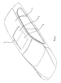
Fig. 1 is a schematic perspective view of a passenger car which is provided with an embodiment of the open roof system according to the invention. -
Fig. 2 is an enlarged schematic perspective view of the open roof system according to the invention used in the car ofFig. 1 . -
Fig. 3 is a schematic perspective exploded view of the open roof system ofFig. 2 . -
Fig. 4 is a plan view of the open roof system according toFig. 3 , whereby the closure means of the open roof system is not shown for clarity reasons. -
Fig. 5b is a schematic perspective view through the connecting part in one embodiment, which is part of the drive cable assembly. -
Fig. 5a is a cross section taken along line V-V inFig. 5b through the connecting part, and showing guiding channels with lateral openings facing each other. -
Fig. 6a is a cross section taken along line VI-VI inFig. 6b through the connecting part, and showing guiding channels with lateral openings facing each other. -
Fig. 6b is a schematic perspective view showing the drive cable assembly, whereby the first and the second part of the assembly is a continuous cable having an acute angle. -
Fig. 7a is a cross section taken inFig. 5B along line VII-VII through the connecting part. -
Fig. 7b is a schematic perspective view, showing the connecting part in an embodiment, in which it is built up of two mirror image pieces. -
Fig. 8 is an enlarged schematic perspective view of the temporary connecting part, shown in a disconnected position. -
Fig. 9 is a schematic perspective view, starting from a perspective cross section at the front of the drawing, showing two guiding channels, having lateral openings facing away from each other. -
Fig. 10 is a schematic perspective view showing guiding channels having joined lateral openings facing a downward direction. -
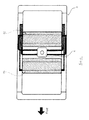
Fig. 11 is a schematic plan view of the open roof system showing, front and rear glass panels, of which only the rear panel is drawn as being transparent, in order to show the windable or rollo screen, guiding channels and drive cable assemblies, lying below the transparent rear panel. -
Fig. 12 is a schematic plan view of the open roof system, showing the front and rear glass panels in a centrally stacked position. -
Fig. 13 is a schematic plan view of the open roof system, showing the front and rear sunshade panels in a centrally stacked position. -
Fig. 14 is a schematic plan view of the open roof system showing the front and rear closure means panels, and the front and rear windable screens. The front panel is drawn in a tilted position and the rear windable screen is drawn in a partly open position. -
Fig. 15 is a schematic plan view of the open roof system showing the front and rear glass panels, and the wind deflector device having slides. The front panel is drawn in a slightly open position, whereas the drive cable assemblies are drawn in a disconnected position from the wind deflector slide. - Referring to
Fig. 1 , a vehicle having an open roof system in its fixed roof 2 is illustrated schematically. Said open roof system comprises a roof opening 1 in a fixed roof 2 of the vehicle, such as a passenger car, and at least first and second closure means 4, 5 for example glass or plastic, at least partly transparent panels as shown inFig. 1 . The first and second closure means can be moved for closing and at least partially opening said roof opening 1 by means explained below. - Below the
roof opening 1, not shown inFig. 1 , but elucidated hereafter, at least first and secondmovable elements - Referring to
Fig. 2 , an open roof system is schematically illustrated, comprising the first and secondmovable elements stationary part 3, particularly a frame, and further comprising amotor 6 and partly shown first guidingchannels stationary part 3 comprises front and rear members and acenter member 12, which are known per se, and not further elucidated and are connected to lateral extrusion guides 11, 11', and saidstationary part 3 connects the open roof system with the body of the vehicle by means of the usual fixing concepts such as screwing, gluing or a combination of these fixing concepts. Themotor 6 may be an electric motor with a gearwheel that transfers the motor torque to themovable elements drive cable assemblies Fig. 2 themotor 6 is positioned on the center member, but it is conceivable that the motor is positioned on the front or rear member ofstationary part 3. - Referring to
Fig. 3 , an open roof system is illustrated schematically and partly in exploded view, such that thestationary part 3 and the first and secondmovable elements movable elements movable elements stationary part 3, and are positioned, seen in a longitudinal direction, adjacent to themotor 6. Saidmotor 6 is positioned on thecenter member 12 ofstationary part 3, such that each of themovable elements - The
stationary part 3 comprises lateral extrusion guides 11, 11'. Said lateral guides 11, 11' comprise supporting channels for guiding the first and secondmovable elements second guiding channels drive cable assemblies movable elements -
Fig. 4 shows only part of the open roof system, namely thestationary part 3, the first and secondmoveable members motor 6, first andsecond guiding channels drive cable assemblies channels first guiding channels drive cable assemblies motor 6, said channels can be conceived as being steel pipes or channels incorporated in either of the front, center or rear members in a manner known per se, running from the motor to a connecting joint with the first channel, in thelateral guide 11, 11'. - Drive
cable assembly first parts second parts part 19. - Each of the
first parts first guiding channels 9, 9'. Saidfirst parts motor 6 is in driving engagement with the first part of thedrive cable assembly 7, 8in one direction through thefirst guiding channels 9, 9'. Via a connection joint they run from thefirst channels 9, 9' into the respective lateral guide, and along a lateral guiding channel, up to where thefirst parts part 19 of the first or secondmovable element - Each of the
first parts motor 6 is in engagement with the drive cable assembly, through thefirst guiding channels 10, 10'. Via a connection joint they run from thechannels 10, 10' into the respective lateral guide, and along a lateral guiding channel, up to where thefirst parts part 19. - The
second parts drive cable assembly first parts part 19, and saidsecond parts second guiding channels 17, 17' in lateral guides 11, 11' from said connectingpart 19 to a connecting part of the first or second movable element at an opposite end.Second parts - When in
Fig. 4 themotor 6 runs in clockwise direction, first and secondmovable elements First parts drive cable assemblies moveable element 51, are driven by the clockwise turning motor in a direction such that the movable beam slides towards the winding shaft ofmovable element 51, and thus retracting themovable element 51. - Because second ends 13", 14" are positioned at the opposite end of
first parts motor 6, this end will move in longitudinal opposite, but substantial parallel direction compared to its first end 13', 14', and towards the firstmovable element -
Second parts drive cable assembly first parts second parts second guiding channel 17, 18 in a second direction towards the secondmovable element motor 6 runs in a clockwise direction. The movable beam slides towards the winding shaft ofmovable element 41, and thus retracting themovable element 41. So by connecting thefirst parts second parts drive cable assemblies movable elements - Referring to
Fig. 5a and 5b , the elongatedsecond part drive cable assembly first part part 19 ofdrive cable assemblies second guiding channels lateral openings 20, 20', along the length of the guide which openings allow theconnection part 19 to protrude from the first into the second guiding channel. Second ends 13", 14" offirst parts drive cable assemblies second parts part 19. Said connectingpart 19 could for instance be made of a plastic molded part, or a metallic molded or casted part. The shape of the connectingpart 19 is such that it has anarrow portion 22 in between the drive cable first andsecond parts 13", 14", 15, 16. Thisnarrow portion 22 is necessary, to make thelateral openings 20, 20' small enough, so that when a driving force is applied to saiddrive cable assemblies lateral openings 20, 20', at an area away from the connectingpart 19. In this embodiment thelateral openings 20, 20' in the first and second guiding channels are facing each other. The length of theopenings 20 is such that they allow movement of the connectingpart 19 over a distance sufficient to allow movement of themovable elements - Referring to
Fig. 6a and 6b , another embodiment of the drive cable assemblies is schematically shown. In this embodiment the drive cable assemblies may also be made of just one cable, whereby the elongated second part is an extension of the flexible first part. Instead of a separate connectingpart 19, connecting two separate drive cables, the first and seconddrive cable parts bend 26 with a small radius (here through 180 degrees) at the position where the cable is routed from thefirst guiding channel second guiding channel 17, 18. At thisparticular bend 26, the transition of the cable thickness must have a similarnarrow portion 22, which protrudes throughlateral openings 20, 20', such that the drive cable cannot escape throughlateral openings 20, 20' in the first andsecond guiding channels cable assemblies second part lateral openings 20, 20' are facing each other. -
Fig. 7a and 7b refer to yet another embodiment of connecting first andsecond parts drive cable assemblies part 19 is split up in two parts, each of which are connected with a separate element, which could be a screw or equivalent. Such embodiment could be used in a situation where the complete drive cable assembly is difficult to assemble into first and second guiding channels. In this embodiment the first and second part of the cable can be assembled in sequence, and afterwards these two parts can be connected to each other by means of theseparate fixing element 31. -
Fig. 8 is referring to another special embodiment of the connectingpart 19. As explained before, the first and second movable elements are driven by onemotor 6. It is clear that when the length of movement of the drive cable assembly that drives the firstmovable element movable element second end 13", 14" having a protruding counterpart which can make a temporary connection with asecond part 27", and thesecond part 27" which is connected to thesecond part drive cable assembly second part 27" can be coupled and decoupled from the first part 27'. When the first 27' andsecond part 27" are coupled , the temporary connectingpart 27 can transfer the driving forces supplied by themotor 6. The coupling between first and second part is a clamping coupling. The first part 27' andsecond part 27" are decoupled by allowing thesecond part 27" to be stopped from moving by a protrudingpart 32 adopted in thesecond guiding channel 17, 17' and thus that secondmovable element part 32 not only stopssecond part 27", but also locks it, at the same place, relative to thesecond guiding channel 17, 17'. Once first andsecond part 27',27" are decoupled, it is necessary to locksecond part 27" in place, in order to couple said first and second part again. The first part 27' of the temporary connectingpart 27 will be moved further under influence of the motor force, and will be decoupled from thesecond part 27" of the temporary connectingpart 27. First part 27' is capable of transferring push and pull forces, this is possible due to the fact that the coupling and decoupling force between first part 27'andsecond part 27" is higher than the normal force required for moving either of the movingelements motor 6 can exert. For connecting the first and second part of the temporary connectingpart 27 the procedure is done in a reverse manner. It will be clear that with this temporary connectingpart 27 as part of thedrive cable assemblies movable elements -
Figs. 9 and 10 refer to alternative embodiments oflateral openings 20, 20' in the first andsecond guiding channel Fig. 9 it is shown that thelateral openings 20, 20' in first andsecond guiding channels part 19, forms a bridge shape, connecting the first andsecond part Fig. 10 thelateral openings 20, 20' in the first andsecond guiding channel - In the embodiment of
Fig. 11 and14 the firstmovable element 4 is a closure means, and the secondmovable element 51 is a windable sunscreen. InFig. 11 , the closure means 4 is driven by a movingmechanism 25, 25' which, when the closure means moves to another position, slides in guiding channels in theguide 11, 11'. Such a closure means and mechanism are known per se. InFig. 11 themechanism 25, 25' is connected to thesecond part drive cable assembly mechanism 25, 25' to thesecond part - In
Fig. 12 an open roof system is drawn in a schematic way, whereby the first and secondmovable elements Fig. 12 . - In
Fig. 13 an open roof system is shown, whereby the first and secondmovable elements Fig. 13 . - Further in
Fig. 15 an open roof system is drawn in a schematic way, whereby the firstmovable element 4 is a closure means, and the second movable element is aslide 24, 24' that moves a wind deflector means 28. In this embodiment the first and secondmovable elements second part drive cable assembly wind deflector slide 24, 24'. The wind deflector means 28 further comprises saidslide 24, 24', which is slidably guided in the lateral guides 11, 12. Said slide comprises a track for engagement with the pin on the wind deflector body. Moving theslide 24, 24' backwards in the guiding channel by movingsecond part drive cable assembly Fig. 15 . The closure means 4 is connected to a movingmechanism 25, 25' and known per se, as described before. Furthermore to allow thesecond part drive cable assembly movable part 24 and the firstmovable part 4 at the same time, a temporary connectingpart 27 is provided. It temporarily connects thesecond part drive cable assembly wind deflector slide 24, 24'. It will be decoupled from saidwind deflector slide 24, 24' when the wind deflector body is in its deployed position. This is necessary because the length of the cable travel to raise the wind deflector body in a deployed position, is shorter than the length of the cable travel necessary to open the closure means. - From the foregoing it will be clear that the invention provides an open roof system which has a solution for driving at least two movable elements which is cost effective and technically favorable.
- The invention is not limited to the embodiments shown in the drawing and described herein before, which may be varied in different manners within the scope of the invention. Aspects of different embodiments may be used in other combinations.
Claims (19)
- Open roof system for a vehicle having an opening (1) in its fixed roof (2), comprising a stationary part (3) to be fixed to the roof (2), at least first and second movable elements (4,5;24;41,42;51,52), which are each movable between a position in which it is retracted, and a position in which it is deployed, a motor (6) for driving the movable elements (4,5;24;41,42;51,52) at least partly between the two positions, at least two drive cable assemblies (7,8) for transferring the torque of the motor (6) to said movable elements (4,5;24;41,42;51,52), whereby the stationary part (3) comprises at least first and second guiding channels (9,9',10,10';17,17') and laterally positioned guides (11,11') for respectively guiding the drive cable assemblies (7,8) and the movable elements (4,5;24;41,42;51,52), whereby the drive cable assemblies (7,8) comprise a flexible first part (13,14) having first and second ends (13',14';13",14"), said first part (13,14) being driven by the motor (6), and whereby said first end (13',14') of said flexible first part (13,14) is connected to the first movable element (4,24,41,42), in a first direction, and said second end (13",14") is guided in a first guiding channel (9,9',10,10') in the lateral guide (11,11'), said second end (13",14") oriented in a direction substantially parallel to the first end (13',14') towards said first movable element (4,24,41,42),
characterized in that the drive cable assembly (7,8) further comprises an elongated second part (15,16), guided in a second guiding channel (17,17') in a second direction towards said second movable element (5,51,52) and connected thereto, in that the second guiding channel (17,17') is oriented substantially parallel to the first guiding channel (9,9',10,10') in the lateral guide (11,11'), and in that, during at least part of the operation, said elongated second part (15,16) moves substantially in the same direction as the second end (13",14") of the first part (13,14) of the cable assembly (7,8). - The open roof system according to claim 1, wherein the elongated second part (15,16) of the drive cable assembly (7,8) is separate from the first part (13,14).
- The open roof system according to claim 2, wherein the first and second parts (13,14;15,16) are connected by a separate connecting part (19).
- The open roof system according to claim 1, wherein the elongated second part (15,16) of the drive cable assembly (7,8) is an extension of the flexible first part (13,14).
- The open roof system according to claim 4, wherein the elongated second part (15,16) is delimited from the first part by a small radius bend (26) in the drive cable assembly (7,8).
- The open roof system according to any one of claims 1 - 5, wherein the second part (15,16) is continuously immovably connected to the flexible first part (13,14).
- The open roof system according to claim 2, wherein the second part (15,16) is temporarily connected to the flexible first part (13,14), by a temporary connecting part (27), such that during a movement between two positions of the first movable element (4,24,41,42), the second elongated part (15,16) is disconnected from the flexible first part (13,14), such that the second moveable element (5,51,52) stops moving.
- The open roof system according to any one of the preceding claims, wherein the elongated second part (15,16) is a flexible part having the same properties as the flexible first part (13, 14).
- The open roof system according to claim 2 or 3,
wherein the elongated second part (15,16) is a substantially stiff part, made of plastic material or metal alloy. - The open roof system according to any one of the preceding claims, wherein the first and second guiding channels (9,9'10,10';17,17') in the lateral guide have lateral openings (20,20') extending along the length of the guide (11,11'), whereby the lateral openings (20,20') are facing each other, and wherein the, connecting part (19) projects through said openings.
- The open roof system according to any one of the preceding claims, wherein the first and second guiding channels (9,9'10,10';17,17') in the lateral guide have lateral openings (20,20') extending along the length of the guide (11,11'), whereby the lateral openings (20,20') are facing each other, and wherein either one of the first, and second part (13,14;15,16) projects through said openings.
- The open roof system according to any one of the preceding claims, wherein the first and second guiding channels (9,9'10,10';17,17') in the lateral guide (11,11') have lateral openings (20,20') extending along the length of the guide, whereby the lateral openings (20,20') are facing each other, and wherein the temporary connecting part (27) projects through said openings.
- The open roof system according to any one of claims 1 - 11, wherein the first and second guiding channel (9,9'10,10';17,17') in the lateral guide (11,11') have lateral openings (20,20') extending along the length of the guide, whereby the lateral openings (20,20') are facing away from each other, and wherein the connecting part (19), projects through said openings (20,20').
- The open roof system according to any of the preceding claims, wherein the at least first and second movable elements (41,51;42,52) are windable sunscreens or stackable sunscreens.
- The open roof system according to any of claims 1 - 13, wherein the at least first and second movable elements (,5) are closure means for closing of the opening in the fixed roof of the panel.
- The open roof system according to any of claims 1 - 13, wherein the at least first and second movable elements are the closure means (4,5) and a slide (24,24') for raising a wind deflector means (28) for deflecting the wind when the closure means is in the open position.
- The open roof system according to claim 9, wherein the elongated second part is connected to a mechanism (25,25') for the movement of the first or second movable element(4,5).
- The open roof system according to any of the preceding claims, wherein the motor (6) is positioned substantially in between the first and the second movable element (4,5;24;41,42; 51,52).
- The open roof system according to any of the preceding claims, wherein the first part (13,14) of the drive cable assembly (7,8) runs from one lateral guide (11) to the opposite lateral guide (11').
Priority Applications (6)
| Application Number | Priority Date | Filing Date | Title |
|---|---|---|---|
| EP12171663.3A EP2674312B1 (en) | 2012-06-12 | 2012-06-12 | Openable roof system for a vehicle |
| US13/910,563 US20130328355A1 (en) | 2012-06-12 | 2013-06-05 | Open roof system for a vehicle |
| KR1020130064459A KR102066406B1 (en) | 2012-06-12 | 2013-06-05 | Open roof system for a vehicle |
| JP2013120500A JP6251494B2 (en) | 2012-06-12 | 2013-06-07 | Open roof system for vehicles |
| CN201310227048.1A CN103481752B (en) | 2012-06-12 | 2013-06-08 | Unlimited canopy system for vehicle |
| US14/274,928 US9145043B2 (en) | 2012-06-12 | 2014-05-12 | Open roof system for a vehicle |
Applications Claiming Priority (1)
| Application Number | Priority Date | Filing Date | Title |
|---|---|---|---|
| EP12171663.3A EP2674312B1 (en) | 2012-06-12 | 2012-06-12 | Openable roof system for a vehicle |
Publications (2)
| Publication Number | Publication Date |
|---|---|
| EP2674312A1 true EP2674312A1 (en) | 2013-12-18 |
| EP2674312B1 EP2674312B1 (en) | 2017-05-03 |
Family
ID=46229350
Family Applications (1)
| Application Number | Title | Priority Date | Filing Date |
|---|---|---|---|
| EP12171663.3A Active EP2674312B1 (en) | 2012-06-12 | 2012-06-12 | Openable roof system for a vehicle |
Country Status (5)
| Country | Link |
|---|---|
| US (1) | US20130328355A1 (en) |
| EP (1) | EP2674312B1 (en) |
| JP (1) | JP6251494B2 (en) |
| KR (1) | KR102066406B1 (en) |
| CN (1) | CN103481752B (en) |
Cited By (2)
| Publication number | Priority date | Publication date | Assignee | Title |
|---|---|---|---|---|
| EP2944491A1 (en) | 2014-05-12 | 2015-11-18 | Inalfa Roof Systems Group B.V. | Open roof system for a vehicle |
| WO2016107678A1 (en) * | 2014-12-29 | 2016-07-07 | Dimas Gmbh | Installation frame for use in motor-vehicle construction and method for producing the installation frame |
Families Citing this family (3)
| Publication number | Priority date | Publication date | Assignee | Title |
|---|---|---|---|---|
| US9145043B2 (en) | 2012-06-12 | 2015-09-29 | Inalfa Roof Systems B.V. | Open roof system for a vehicle |
| DE102016108092A1 (en) * | 2016-05-02 | 2017-11-02 | Webasto SE | Arrangement for a vehicle roof |
| CN111347852B (en) * | 2018-12-24 | 2024-03-08 | 英纳法天窗系统集团有限公司 | Open roof construction for a vehicle |
Citations (4)
| Publication number | Priority date | Publication date | Assignee | Title |
|---|---|---|---|---|
| DE10327352A1 (en) * | 2002-06-21 | 2004-01-15 | Webasto Vehicle Systems International Gmbh | Device for the transmission of kinematic forces with several cables and single drive pinion and use in the actuation of the movable elements of a motor vehicle roof |
| FR2926497A1 (en) * | 2008-01-18 | 2009-07-24 | Peugeot Citroen Automobiles Sa | Front and rear parts occulting device for cielo type panoramic roof of motor vehicle, has cables whose intermediate parts are driven in opposed directions, by wheel such that one blind is pulled out when other blind is pushed |
| FR2926496A1 (en) * | 2008-01-18 | 2009-07-24 | Peugeot Citroen Automobiles Sa | Picture window e.g. cielo type panoramic roof, obstructing device for motor vehicle, has driving units provided with two wheels and mounted on axle, and cables designated to driven in opposite direction by wheels |
| US20120139284A1 (en) * | 2010-12-07 | 2012-06-07 | Hyundai Motor Company | Panoramic roof apparatus for vehicle |
Family Cites Families (11)
| Publication number | Priority date | Publication date | Assignee | Title |
|---|---|---|---|---|
| JPS5970225A (en) * | 1982-10-14 | 1984-04-20 | Iseki & Co Ltd | Sunshade device for vehicle driver seat |
| DE3801812A1 (en) * | 1988-01-22 | 1989-08-03 | Altenkirchener Kunststoff | Drainage device for water from sliding roofs |
| DE4022928C1 (en) * | 1990-07-19 | 1992-02-06 | Webasto Ag Fahrzeugtechnik, 8035 Stockdorf, De | |
| JP3035631B2 (en) * | 1991-01-17 | 2000-04-24 | マツダ株式会社 | Drive device for vehicle sliding roof |
| CN2151034Y (en) * | 1992-10-22 | 1993-12-29 | 郑炳盛 | Rain-proof adjustable skylight of car |
| JP2001220946A (en) * | 1999-12-03 | 2001-08-17 | Nippon Cable Syst Inc | Pull-cable type opening/closing device for sunroof and the like |
| DE10110013C2 (en) * | 2001-03-01 | 2003-06-26 | Webasto Vehicle Sys Int Gmbh | Openable vehicle roof with two transparent lids |
| JP4247751B2 (en) * | 2006-08-10 | 2009-04-02 | トヨタ紡織株式会社 | Sunshade equipment |
| US8814258B2 (en) * | 2008-08-15 | 2014-08-26 | Ford Global Technologies, Llc | Panoramic vehicle roof module assemblies |
| EP2338716B1 (en) * | 2009-12-23 | 2012-11-21 | Inalfa Roof Systems Group B.V. | Sunshade assembly and open roof construction provided therewith |
| EP2380763B1 (en) * | 2010-04-20 | 2013-06-12 | Inalfa Roof Systems Group B.V. | Open roof construction for a vehicle |
-
2012
- 2012-06-12 EP EP12171663.3A patent/EP2674312B1/en active Active
-
2013
- 2013-06-05 KR KR1020130064459A patent/KR102066406B1/en active Active
- 2013-06-05 US US13/910,563 patent/US20130328355A1/en not_active Abandoned
- 2013-06-07 JP JP2013120500A patent/JP6251494B2/en active Active
- 2013-06-08 CN CN201310227048.1A patent/CN103481752B/en active Active
Patent Citations (5)
| Publication number | Priority date | Publication date | Assignee | Title |
|---|---|---|---|---|
| DE10327352A1 (en) * | 2002-06-21 | 2004-01-15 | Webasto Vehicle Systems International Gmbh | Device for the transmission of kinematic forces with several cables and single drive pinion and use in the actuation of the movable elements of a motor vehicle roof |
| FR2926497A1 (en) * | 2008-01-18 | 2009-07-24 | Peugeot Citroen Automobiles Sa | Front and rear parts occulting device for cielo type panoramic roof of motor vehicle, has cables whose intermediate parts are driven in opposed directions, by wheel such that one blind is pulled out when other blind is pushed |
| FR2926496A1 (en) * | 2008-01-18 | 2009-07-24 | Peugeot Citroen Automobiles Sa | Picture window e.g. cielo type panoramic roof, obstructing device for motor vehicle, has driving units provided with two wheels and mounted on axle, and cables designated to driven in opposite direction by wheels |
| FR2926497B1 (en) | 2008-01-18 | 2010-03-26 | Peugeot Citroen Automobiles Sa | DEVICE FOR OCCULATING A PANORAMIC WINDOW OF A MOTOR VEHICLE WITH A SLIDING CURTAIN CONTROLLED BY TWO CABLES DRIVEN BY A CENTRAL ENGINE |
| US20120139284A1 (en) * | 2010-12-07 | 2012-06-07 | Hyundai Motor Company | Panoramic roof apparatus for vehicle |
Cited By (2)
| Publication number | Priority date | Publication date | Assignee | Title |
|---|---|---|---|---|
| EP2944491A1 (en) | 2014-05-12 | 2015-11-18 | Inalfa Roof Systems Group B.V. | Open roof system for a vehicle |
| WO2016107678A1 (en) * | 2014-12-29 | 2016-07-07 | Dimas Gmbh | Installation frame for use in motor-vehicle construction and method for producing the installation frame |
Also Published As
| Publication number | Publication date |
|---|---|
| KR102066406B1 (en) | 2020-01-15 |
| JP6251494B2 (en) | 2017-12-20 |
| KR20130139168A (en) | 2013-12-20 |
| US20130328355A1 (en) | 2013-12-12 |
| CN103481752A (en) | 2014-01-01 |
| EP2674312B1 (en) | 2017-05-03 |
| JP2013256285A (en) | 2013-12-26 |
| CN103481752B (en) | 2016-12-28 |
Similar Documents
| Publication | Publication Date | Title |
|---|---|---|
| EP2151339B1 (en) | Sunshade assembly and open roof construction provided therewith | |
| US8366187B2 (en) | Sunroof apparatus | |
| JP4797091B2 (en) | Shade panel interlocking mechanism in sunroof equipment | |
| US9039076B2 (en) | Open roof construction for a vehicle | |
| EP2674312B1 (en) | Openable roof system for a vehicle | |
| US20040041434A1 (en) | Folding roof for vehicle with sliding elements | |
| US9649918B2 (en) | Sunshade assembly | |
| KR102291572B1 (en) | Shading system for an automotive vehicle | |
| CN114845893B (en) | Roof comprising a roof opening system with two movement units | |
| CN112805167A (en) | Roof with a roof opening system and a drive for a movement unit | |
| US9145043B2 (en) | Open roof system for a vehicle | |
| CN111137118B (en) | Roof system for a vehicle | |
| US9586463B2 (en) | Top for an openable vehicle roof | |
| EP2944491B1 (en) | Open roof system for a vehicle | |
| JP7752751B2 (en) | Device for vehicle roof and vehicle roof | |
| MXPA06015125A (en) | Concealment device for vehicle roofs with at least one transparent part . | |
| CN106470860A (en) | There is the glass sunroof of the removable panel being controlled by shuttle | |
| DE102021214299B4 (en) | Shading device for a window section of a motor vehicle | |
| CN111546862B (en) | Open roof assembly | |
| EP1650069B1 (en) | Open roof construction | |
| JPH0585183A (en) | Upper car body |
Legal Events
| Date | Code | Title | Description |
|---|---|---|---|
| PUAI | Public reference made under article 153(3) epc to a published international application that has entered the european phase |
Free format text: ORIGINAL CODE: 0009012 |
|
| AK | Designated contracting states |
Kind code of ref document: A1 Designated state(s): AL AT BE BG CH CY CZ DE DK EE ES FI FR GB GR HR HU IE IS IT LI LT LU LV MC MK MT NL NO PL PT RO RS SE SI SK SM TR |
|
| AX | Request for extension of the european patent |
Extension state: BA ME |
|
| 17P | Request for examination filed |
Effective date: 20140616 |
|
| RBV | Designated contracting states (corrected) |
Designated state(s): AL AT BE BG CH CY CZ DE DK EE ES FI FR GB GR HR HU IE IS IT LI LT LU LV MC MK MT NL NO PL PT RO RS SE SI SK SM TR |
|
| GRAP | Despatch of communication of intention to grant a patent |
Free format text: ORIGINAL CODE: EPIDOSNIGR1 |
|
| INTG | Intention to grant announced |
Effective date: 20161221 |
|
| GRAS | Grant fee paid |
Free format text: ORIGINAL CODE: EPIDOSNIGR3 |
|
| GRAA | (expected) grant |
Free format text: ORIGINAL CODE: 0009210 |
|
| AK | Designated contracting states |
Kind code of ref document: B1 Designated state(s): AL AT BE BG CH CY CZ DE DK EE ES FI FR GB GR HR HU IE IS IT LI LT LU LV MC MK MT NL NO PL PT RO RS SE SI SK SM TR |
|
| REG | Reference to a national code |
Ref country code: GB Ref legal event code: FG4D |
|
| REG | Reference to a national code |
Ref country code: AT Ref legal event code: REF Ref document number: 889558 Country of ref document: AT Kind code of ref document: T Effective date: 20170515 Ref country code: CH Ref legal event code: EP |
|
| REG | Reference to a national code |
Ref country code: IE Ref legal event code: FG4D |
|
| REG | Reference to a national code |
Ref country code: DE Ref legal event code: R096 Ref document number: 602012031833 Country of ref document: DE |
|
| REG | Reference to a national code |
Ref country code: FR Ref legal event code: PLFP Year of fee payment: 6 |
|
| REG | Reference to a national code |
Ref country code: NL Ref legal event code: MP Effective date: 20170503 |
|
| REG | Reference to a national code |
Ref country code: AT Ref legal event code: MK05 Ref document number: 889558 Country of ref document: AT Kind code of ref document: T Effective date: 20170503 |
|
| REG | Reference to a national code |
Ref country code: LT Ref legal event code: MG4D |
|
| PG25 | Lapsed in a contracting state [announced via postgrant information from national office to epo] |
Ref country code: HR Free format text: LAPSE BECAUSE OF FAILURE TO SUBMIT A TRANSLATION OF THE DESCRIPTION OR TO PAY THE FEE WITHIN THE PRESCRIBED TIME-LIMIT Effective date: 20170503 Ref country code: NO Free format text: LAPSE BECAUSE OF FAILURE TO SUBMIT A TRANSLATION OF THE DESCRIPTION OR TO PAY THE FEE WITHIN THE PRESCRIBED TIME-LIMIT Effective date: 20170803 Ref country code: GR Free format text: LAPSE BECAUSE OF FAILURE TO SUBMIT A TRANSLATION OF THE DESCRIPTION OR TO PAY THE FEE WITHIN THE PRESCRIBED TIME-LIMIT Effective date: 20170804 Ref country code: AT Free format text: LAPSE BECAUSE OF FAILURE TO SUBMIT A TRANSLATION OF THE DESCRIPTION OR TO PAY THE FEE WITHIN THE PRESCRIBED TIME-LIMIT Effective date: 20170503 Ref country code: FI Free format text: LAPSE BECAUSE OF FAILURE TO SUBMIT A TRANSLATION OF THE DESCRIPTION OR TO PAY THE FEE WITHIN THE PRESCRIBED TIME-LIMIT Effective date: 20170503 Ref country code: ES Free format text: LAPSE BECAUSE OF FAILURE TO SUBMIT A TRANSLATION OF THE DESCRIPTION OR TO PAY THE FEE WITHIN THE PRESCRIBED TIME-LIMIT Effective date: 20170503 Ref country code: LT Free format text: LAPSE BECAUSE OF FAILURE TO SUBMIT A TRANSLATION OF THE DESCRIPTION OR TO PAY THE FEE WITHIN THE PRESCRIBED TIME-LIMIT Effective date: 20170503 |
|
| PG25 | Lapsed in a contracting state [announced via postgrant information from national office to epo] |
Ref country code: NL Free format text: LAPSE BECAUSE OF FAILURE TO SUBMIT A TRANSLATION OF THE DESCRIPTION OR TO PAY THE FEE WITHIN THE PRESCRIBED TIME-LIMIT Effective date: 20170503 Ref country code: IS Free format text: LAPSE BECAUSE OF FAILURE TO SUBMIT A TRANSLATION OF THE DESCRIPTION OR TO PAY THE FEE WITHIN THE PRESCRIBED TIME-LIMIT Effective date: 20170903 Ref country code: LV Free format text: LAPSE BECAUSE OF FAILURE TO SUBMIT A TRANSLATION OF THE DESCRIPTION OR TO PAY THE FEE WITHIN THE PRESCRIBED TIME-LIMIT Effective date: 20170503 Ref country code: SE Free format text: LAPSE BECAUSE OF FAILURE TO SUBMIT A TRANSLATION OF THE DESCRIPTION OR TO PAY THE FEE WITHIN THE PRESCRIBED TIME-LIMIT Effective date: 20170503 Ref country code: PL Free format text: LAPSE BECAUSE OF FAILURE TO SUBMIT A TRANSLATION OF THE DESCRIPTION OR TO PAY THE FEE WITHIN THE PRESCRIBED TIME-LIMIT Effective date: 20170503 Ref country code: RS Free format text: LAPSE BECAUSE OF FAILURE TO SUBMIT A TRANSLATION OF THE DESCRIPTION OR TO PAY THE FEE WITHIN THE PRESCRIBED TIME-LIMIT Effective date: 20170503 Ref country code: BG Free format text: LAPSE BECAUSE OF FAILURE TO SUBMIT A TRANSLATION OF THE DESCRIPTION OR TO PAY THE FEE WITHIN THE PRESCRIBED TIME-LIMIT Effective date: 20170803 |
|
| PG25 | Lapsed in a contracting state [announced via postgrant information from national office to epo] |
Ref country code: CZ Free format text: LAPSE BECAUSE OF FAILURE TO SUBMIT A TRANSLATION OF THE DESCRIPTION OR TO PAY THE FEE WITHIN THE PRESCRIBED TIME-LIMIT Effective date: 20170503 Ref country code: SK Free format text: LAPSE BECAUSE OF FAILURE TO SUBMIT A TRANSLATION OF THE DESCRIPTION OR TO PAY THE FEE WITHIN THE PRESCRIBED TIME-LIMIT Effective date: 20170503 Ref country code: RO Free format text: LAPSE BECAUSE OF FAILURE TO SUBMIT A TRANSLATION OF THE DESCRIPTION OR TO PAY THE FEE WITHIN THE PRESCRIBED TIME-LIMIT Effective date: 20170503 Ref country code: DK Free format text: LAPSE BECAUSE OF FAILURE TO SUBMIT A TRANSLATION OF THE DESCRIPTION OR TO PAY THE FEE WITHIN THE PRESCRIBED TIME-LIMIT Effective date: 20170503 Ref country code: EE Free format text: LAPSE BECAUSE OF FAILURE TO SUBMIT A TRANSLATION OF THE DESCRIPTION OR TO PAY THE FEE WITHIN THE PRESCRIBED TIME-LIMIT Effective date: 20170503 |
|
| REG | Reference to a national code |
Ref country code: CH Ref legal event code: PL |
|
| REG | Reference to a national code |
Ref country code: DE Ref legal event code: R097 Ref document number: 602012031833 Country of ref document: DE |
|
| PG25 | Lapsed in a contracting state [announced via postgrant information from national office to epo] |
Ref country code: IT Free format text: LAPSE BECAUSE OF FAILURE TO SUBMIT A TRANSLATION OF THE DESCRIPTION OR TO PAY THE FEE WITHIN THE PRESCRIBED TIME-LIMIT Effective date: 20170503 Ref country code: SM Free format text: LAPSE BECAUSE OF FAILURE TO SUBMIT A TRANSLATION OF THE DESCRIPTION OR TO PAY THE FEE WITHIN THE PRESCRIBED TIME-LIMIT Effective date: 20170503 |
|
| PLBE | No opposition filed within time limit |
Free format text: ORIGINAL CODE: 0009261 |
|
| STAA | Information on the status of an ep patent application or granted ep patent |
Free format text: STATUS: NO OPPOSITION FILED WITHIN TIME LIMIT |
|
| REG | Reference to a national code |
Ref country code: IE Ref legal event code: MM4A |
|
| 26N | No opposition filed |
Effective date: 20180206 |
|
| GBPC | Gb: european patent ceased through non-payment of renewal fee |
Effective date: 20170803 |
|
| PG25 | Lapsed in a contracting state [announced via postgrant information from national office to epo] |
Ref country code: CH Free format text: LAPSE BECAUSE OF NON-PAYMENT OF DUE FEES Effective date: 20170630 Ref country code: LU Free format text: LAPSE BECAUSE OF NON-PAYMENT OF DUE FEES Effective date: 20170612 Ref country code: IE Free format text: LAPSE BECAUSE OF NON-PAYMENT OF DUE FEES Effective date: 20170612 Ref country code: LI Free format text: LAPSE BECAUSE OF NON-PAYMENT OF DUE FEES Effective date: 20170630 |
|
| PG25 | Lapsed in a contracting state [announced via postgrant information from national office to epo] |
Ref country code: SI Free format text: LAPSE BECAUSE OF FAILURE TO SUBMIT A TRANSLATION OF THE DESCRIPTION OR TO PAY THE FEE WITHIN THE PRESCRIBED TIME-LIMIT Effective date: 20170503 |
|
| REG | Reference to a national code |
Ref country code: BE Ref legal event code: MM Effective date: 20170630 |
|
| REG | Reference to a national code |
Ref country code: FR Ref legal event code: PLFP Year of fee payment: 7 |
|
| PG25 | Lapsed in a contracting state [announced via postgrant information from national office to epo] |
Ref country code: GB Free format text: LAPSE BECAUSE OF NON-PAYMENT OF DUE FEES Effective date: 20170803 |
|
| PG25 | Lapsed in a contracting state [announced via postgrant information from national office to epo] |
Ref country code: BE Free format text: LAPSE BECAUSE OF NON-PAYMENT OF DUE FEES Effective date: 20170630 |
|
| PG25 | Lapsed in a contracting state [announced via postgrant information from national office to epo] |
Ref country code: MT Free format text: LAPSE BECAUSE OF NON-PAYMENT OF DUE FEES Effective date: 20170612 |
|
| PG25 | Lapsed in a contracting state [announced via postgrant information from national office to epo] |
Ref country code: MC Free format text: LAPSE BECAUSE OF FAILURE TO SUBMIT A TRANSLATION OF THE DESCRIPTION OR TO PAY THE FEE WITHIN THE PRESCRIBED TIME-LIMIT Effective date: 20170503 Ref country code: HU Free format text: LAPSE BECAUSE OF FAILURE TO SUBMIT A TRANSLATION OF THE DESCRIPTION OR TO PAY THE FEE WITHIN THE PRESCRIBED TIME-LIMIT; INVALID AB INITIO Effective date: 20120612 |
|
| PG25 | Lapsed in a contracting state [announced via postgrant information from national office to epo] |
Ref country code: CY Free format text: LAPSE BECAUSE OF NON-PAYMENT OF DUE FEES Effective date: 20170503 |
|
| PG25 | Lapsed in a contracting state [announced via postgrant information from national office to epo] |
Ref country code: MK Free format text: LAPSE BECAUSE OF FAILURE TO SUBMIT A TRANSLATION OF THE DESCRIPTION OR TO PAY THE FEE WITHIN THE PRESCRIBED TIME-LIMIT Effective date: 20170503 |
|
| PG25 | Lapsed in a contracting state [announced via postgrant information from national office to epo] |
Ref country code: TR Free format text: LAPSE BECAUSE OF FAILURE TO SUBMIT A TRANSLATION OF THE DESCRIPTION OR TO PAY THE FEE WITHIN THE PRESCRIBED TIME-LIMIT Effective date: 20170503 |
|
| PG25 | Lapsed in a contracting state [announced via postgrant information from national office to epo] |
Ref country code: PT Free format text: LAPSE BECAUSE OF FAILURE TO SUBMIT A TRANSLATION OF THE DESCRIPTION OR TO PAY THE FEE WITHIN THE PRESCRIBED TIME-LIMIT Effective date: 20170503 |
|
| PG25 | Lapsed in a contracting state [announced via postgrant information from national office to epo] |
Ref country code: AL Free format text: LAPSE BECAUSE OF FAILURE TO SUBMIT A TRANSLATION OF THE DESCRIPTION OR TO PAY THE FEE WITHIN THE PRESCRIBED TIME-LIMIT Effective date: 20170503 |
|
| PGFP | Annual fee paid to national office [announced via postgrant information from national office to epo] |
Ref country code: FR Payment date: 20240625 Year of fee payment: 13 |
|
| PGFP | Annual fee paid to national office [announced via postgrant information from national office to epo] |
Ref country code: DE Payment date: 20250627 Year of fee payment: 14 |
|
| PG25 | Lapsed in a contracting state [announced via postgrant information from national office to epo] |
Ref country code: FR Free format text: LAPSE BECAUSE OF NON-PAYMENT OF DUE FEES Effective date: 20250630 |