EP2674236A1 - Modular interface for tools having structure pairs acting at right angles to the axial direction - Google Patents
Modular interface for tools having structure pairs acting at right angles to the axial direction Download PDFInfo
- Publication number
- EP2674236A1 EP2674236A1 EP13003053.9A EP13003053A EP2674236A1 EP 2674236 A1 EP2674236 A1 EP 2674236A1 EP 13003053 A EP13003053 A EP 13003053A EP 2674236 A1 EP2674236 A1 EP 2674236A1
- Authority
- EP
- European Patent Office
- Prior art keywords
- assembly
- tool
- pairs
- shift lever
- structures
- Prior art date
- Legal status (The legal status is an assumption and is not a legal conclusion. Google has not performed a legal analysis and makes no representation as to the accuracy of the status listed.)
- Withdrawn
Links
- 239000007787 solid Substances 0.000 claims description 15
- 230000008878 coupling Effects 0.000 description 3
- 238000010168 coupling process Methods 0.000 description 3
- 238000005859 coupling reaction Methods 0.000 description 3
- 230000007246 mechanism Effects 0.000 description 3
- 230000007704 transition Effects 0.000 description 3
- 230000000903 blocking effect Effects 0.000 description 2
- 238000006073 displacement reaction Methods 0.000 description 2
- 239000000314 lubricant Substances 0.000 description 2
- 230000003716 rejuvenation Effects 0.000 description 2
- 241000237942 Conidae Species 0.000 description 1
- 229910000831 Steel Inorganic materials 0.000 description 1
- 230000009471 action Effects 0.000 description 1
- 230000005540 biological transmission Effects 0.000 description 1
- 230000008859 change Effects 0.000 description 1
- 230000000295 complement effect Effects 0.000 description 1
- 238000001816 cooling Methods 0.000 description 1
- 230000001419 dependent effect Effects 0.000 description 1
- 238000005553 drilling Methods 0.000 description 1
- 230000000694 effects Effects 0.000 description 1
- 238000003780 insertion Methods 0.000 description 1
- 230000037431 insertion Effects 0.000 description 1
- 238000009434 installation Methods 0.000 description 1
- 230000001788 irregular Effects 0.000 description 1
- 230000013011 mating Effects 0.000 description 1
- 230000005012 migration Effects 0.000 description 1
- 238000013508 migration Methods 0.000 description 1
- 238000007789 sealing Methods 0.000 description 1
- 239000010959 steel Substances 0.000 description 1
- 210000002435 tendon Anatomy 0.000 description 1
Images


Classifications
-
- B—PERFORMING OPERATIONS; TRANSPORTING
- B23—MACHINE TOOLS; METAL-WORKING NOT OTHERWISE PROVIDED FOR
- B23B—TURNING; BORING
- B23B29/00—Holders for non-rotary cutting tools; Boring bars or boring heads; Accessories for tool holders
- B23B29/04—Tool holders for a single cutting tool
- B23B29/046—Tool holders for a single cutting tool with an intermediary toolholder
-
- B—PERFORMING OPERATIONS; TRANSPORTING
- B23—MACHINE TOOLS; METAL-WORKING NOT OTHERWISE PROVIDED FOR
- B23B—TURNING; BORING
- B23B31/00—Chucks; Expansion mandrels; Adaptations thereof for remote control
- B23B31/02—Chucks
- B23B31/10—Chucks characterised by the retaining or gripping devices or their immediate operating means
- B23B31/103—Retention by pivotal elements, e.g. catches, pawls
-
- B—PERFORMING OPERATIONS; TRANSPORTING
- B23—MACHINE TOOLS; METAL-WORKING NOT OTHERWISE PROVIDED FOR
- B23B—TURNING; BORING
- B23B31/00—Chucks; Expansion mandrels; Adaptations thereof for remote control
- B23B31/02—Chucks
- B23B31/10—Chucks characterised by the retaining or gripping devices or their immediate operating means
- B23B31/107—Retention by laterally-acting detents, e.g. pins, screws, wedges; Retention by loose elements, e.g. balls
- B23B31/1075—Retention by screws
-
- B—PERFORMING OPERATIONS; TRANSPORTING
- B23—MACHINE TOOLS; METAL-WORKING NOT OTHERWISE PROVIDED FOR
- B23B—TURNING; BORING
- B23B31/00—Chucks; Expansion mandrels; Adaptations thereof for remote control
- B23B31/02—Chucks
- B23B31/10—Chucks characterised by the retaining or gripping devices or their immediate operating means
- B23B31/113—Retention by bayonet connection
-
- B—PERFORMING OPERATIONS; TRANSPORTING
- B23—MACHINE TOOLS; METAL-WORKING NOT OTHERWISE PROVIDED FOR
- B23B—TURNING; BORING
- B23B2231/00—Details of chucks, toolholder shanks or tool shanks
- B23B2231/04—Adapters
Definitions
- the invention relates to an interface comprising a first assembly holding a processing element and a second - the processing element bearing or having - assembly, wherein the processing element is a tool or a tool holder with inserted tool.
- the first subassembly has a contact surface acting in the axial direction - in the direction of the second subassembly - or a group of at least three contact points lying in one plane.
- the second subassembly has at least one abutment surface acting in the axial direction - in the direction of the first subassembly - or a group of at least three contact points lying in one plane, for contacting the contact surface or the corresponding contact points of the first subassembly.
- the tool adapter for detachable and replaceable attachment in a tool holder of a machine tool known.
- the tool adapter consists inter alia of a conical section and a cylindrical collar.
- In the cylindrical collar are two opposite frusto-conical transverse holes, are screwed into the screwed into the tool holder clamping bolt with their frustoconical tips.
- the clamping bolts By screwing in the clamping bolts, the tool adapter is clamped against the cylindrical collar.
- the clamping bolts can be tightened only one after the other.
- possible eccentricities of the threaded or tapered cones are transferred to the tool.
- both clamping bolts must be unscrewed so far when changing the tool adapter, that there is a risk that they fall out.
- the present invention is based on the problem of developing an interface of a first module and a second module, which ensures easy handling with a high repeatability with respect to the position of the second module relative to the first module with each tool change off-center loaded tools.
- the plane formed by the planar mounting joint is cut at least by two solid structures which engage in corresponding hollow structures with which they each form a pair of structures. It is in each case the solid or the hollow structure of a structure pair in the first or the second Assembly arranged.
- the direction of the center line of the tool carrier is oriented in the radial direction or deviates from it by up to ⁇ 45 degrees.
- at least one or all structure pairs have no degree of freedom.
- each pair of structure pieces has a degree of freedom radially oriented with respect to the center line of the tool carrier, or deviates from it by up to ⁇ 45 degrees.
- one structural pair part each has one degree of freedom, wherein at least two degrees of freedom have different directions.
- at least one solid structure can be omitted. With two and more than two structural pairs located in the planar assembly joint, at least two structural pairs form a group which can be arranged alternately in at least two positions.
- a second module with respect to a first module is positioned against rotation and clamped repeatable.
- a shift lever element is installed between the two components forming an interface as an intermediate element.
- the shift lever element is mounted in the first assembly pivot and / or longitudinally displaceable. It has as coupling elements for the second module, for example, a plurality of inner webs.
- the second module has corresponding web-like engagement elements. The latter engage behind the coupling elements of the shift lever element when inserting the second module into the first.
- the engaging behind the coupling elements through the rear grip elements can be compared with the engaging behind a conventional bayonet closure.
- the first assembly is a tool carrier, e.g. is arranged exchangeably in a rotating spindle head of a tool changing unit.
- the tool carrier may e.g. a VDI adapter to DIN 69880, an SK adapter to DIN 69871 or a HSK adapter form A + C to ISO 12164.
- the second assembly usually represents a tool-carrying tool holder or just a tool that is directly adaptable to the first assembly.
- the here preferably to exciting tools are loaded by cutting forces acting eccentrically to the center line of the respective tool holder.
- u.a. arranged to prevent rotation between the tool carrier and the tool holder at least two structure pairs. These pairs of structures prevent almost any play and repeat exactly any relative movement between the tool carrier and the tool holder, which is oriented transversely to the axial direction.
- the first assembly may also be a non-rotating tool carrier as used as a steel holder of a top slide of a conventional lathe.
- the second assembly is in this case arranged in a tool holder turning tool as a tool or cutter carrier.
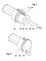
- the FIG. 1 shows as a first component of the modular interface a tool carrier (20) with an interchangeable tool holder (90) as a second component of the modular interface.
- the tool holder (90) carries as a tool (120), for example, an internal turning tool.
- the tool carrier (20) can be stored for example in the spindle of a tool unit. The corresponding spindle and the associated tool unit are not shown here.
- This tensioning gear section (21), cf. FIG. 7 has a cylindrical outer wall (22), a cylindrical inner wall (23) - than Part of a tool holder (90) receiving recess (30) - and an eg planar end face (24).
- fitting holes (25) In the front or contact surface (24) are after FIG. 3 arranged four fitting holes (25), which, starting from the contact surface (24), for example, 2.7 mm deep.
- the narrow tolerated diameter of the fitting holes (25) is eg 6 mm.
- the center lines (26) of the fitting bores (25) lie on an imaginary cylinder whose center line coincides with the center line (39) of the tool carrier (20).
- the mutually parallel center lines (26) are equidistant distributed on the imaginary cylinder, which here has a diameter of 27.5 mm, distributed, see. also FIG. 18 ,
- the tensioning gear section (21) which adjoins the contact surface (24) has, with a tool carrier (20) with e.g. 50 mm outside diameter has a depth of e.g. 17.2 mm, while its wall thickness is e.g. Measures 9 mm.
- the inner wall (23) ends e.g. in front of a flat inner end face (28), in which a truncated cone-shaped portion (31) adjoins.
- This section (31) has here, e.g. a maximum diameter of 20 mm and a cone angle of 16 degrees. The length of this truncated cone-shaped portion (31) is approximately 14.2 mm.
- the section (31) is followed by an at least partially cylindrical bore (32). It ends before a e.g. truncated cone-shaped inner end face (29) into which, if necessary, a cooling and / or Schmierstoffzu Munichbohrung (35) opens.
- a sealing ring can be used, which seals the holes (32, 97) against each other.
- the tensioning gear portion (21) of the tool carrier (20) has, for example, two opposing bores (36, 38).
- FIG. 6 has the bore (36), for example, an internal thread, for example, the fine thread M 10 x 1.
- a special countersunk screw (40) is firmly screwed in the threaded hole (36).
- the countersunk head of this screw (40) which has a tool recess (42), is clamped against the depression of the threaded hole (36).
- the other end of the special countersunk screw (40) has an eg crowned, possibly spherically curved bearing journal (41), which projects into the recess (30).
- the diameter of the journal (41) is for example 6.5 mm.
- the eccentric shaft (51) has a smooth, cylindrical outer surface (52) which sits in a likewise smooth-walled bore (38) with little play or a transition fit.
- a partial annular groove (53) is incorporated in the central region of the outer surface (52) in the central region of the outer surface (52) has a partial annular groove (53) is incorporated.
- the Operaringnut (53) completely covers the lower half of the illustrated cross section.
- the tangential Operaringnutausset (54) are shown.
- the centers of the groove bottoms of Operaringnutausset (54) are almost parallel straight lines, since the full cross section of Operaringnut (53), for example, covers 185 degrees of the Exzenterwellen influencess.
- the sectionringnut (53) has in the right half of the cross section, for example, a circular section-shaped cross-section.
- the diameter of the circle belonging to this cross-section is for example 3.3 mm.
- the height of the circular segment-shaped cross section measures, for example, 39% of the circle diameter.
- the eccentric shaft (51) has a non-cylindrical eccentric pin (55) having an active displacement surface (46) and a passive abutment surface (47). To this end, he has across his axis (56) a non-circular cross-section, which consists of two circular sections that contact each other along their tendons. The diameter of the circular sections is eg 8 mm, while their arc height measures for example 2.25 mm. The eccentricity of the adjustment surface (46) is for example 0.8 mm. She is after FIG. 20 offset downwards from the center line (56). The eccentricity of the stop surface (47) measures 3.3 mm and is also offset from the center line (56) down.
- adjustment (46) and stop surfaces (47) at least partially spherical, barrel-shaped or spherically curved outer surfaces.
- the eccentric pin-free end face of the eccentric shaft (51) has a tool recess (57) with, for example, a hexagonal hollow cross-section. Between the tool recess (57) and the radial outer surface (52) extends, for example, a 0.5 mm deep groove (48) or notch for marking the position of the eccentric pin (51), cf. FIGS. 20 and 21 , The groove (48) sits behind FIG. 20 below the eccentric pin (51).
- the tool recess (57) of the eccentric shaft (51) is e.g. larger than the tool recess (42) of the special countersunk screw (40).
- the tool holder (90) In the recess (30) is stuck FIG. 6 the tool holder (90).
- the latter comprises a flange portion (91), a locking portion (100), a pin portion (110) and an end portion (112).
- the almost disk-shaped flange section (91) here has a cylindrical outer surface, the outer diameter of which corresponds, for example, to the adjacent outer diameter of the tool carrier (20).
- the flange section (91) has, for example, a plane end face (98), in the middle of which a cylindrical bore (92) for receiving the tool (120) is arranged.
- the tool (120) here an internal turning tool, is fixed via its shank (121) with three clamping screws (126) in the tool holder (90).
- the clamping screws (126) sit in corresponding threaded holes (125).
- the tool recesses of the clamping screws (126) have, for example, a smaller hollow cross-section than the tool recess (57) of the tool holder (90).
- the tool (120) can also be secured in the tool holder (90) by means of a transverse press fit or the like.
- a tool (190) in the form of an external turning tool inserted in the tool carrier (20) a tool (190) in the form of an external turning tool.
- This external turning tool (190) which carries an indexable insert (192) here, has an interface shape such that it can be adapted in a manner comparable to the tool holder (90) in the tool carrier (20).
- the back of the flange portion (91), cf. FIG. 5 has a planar end face (93), which serves as a contact surface for contacting the tool carrier (20).
- the end face (93) is optionally divided by even or odd grooves in different zones, so that there island-like contact surfaces arise whose respective surface area, for example, is only a few square millimeters.
- the contact surfaces (24) and (93), which have been machined to fit one another, can be truncated cone-shaped or spherically curved.
- the cone angle would then be between 170 and 190 degrees, while the radius of curvature would be greater than 200 mm.
- each fitting screws (117) are screwed.
- the tightly tolerated head diameter of the fitting screws (117) is eg 6 mm.
- the front or contact surface (93) is separated by a shaft shoulder (95).
- the latter has a flat ejection surface (96) and a truncated cone-shaped radial wall.
- the cone angle of the radial wall is e.g. 50 degrees.
- the flange portion (91) - viewed in the axial direction (1) - has e.g. a slightly larger wall thickness than in the region of the end face (93).
- the ejection surface (96) is followed by a short cylindrical section (102) having an annular groove (103) with e.g. cylindrical groove bottom (104).
- the groove bottom (104) has e.g. a diameter of 21.2 mm.
- the annular groove (103) has e.g. a frustoconical flank whose flank angle measures 30 degrees.
- the opposite groove flank has a flat flank surface.
- This flank surface belongs to two rear grip webs (105, 106).
- the rearward webs (105, 106) have e.g. a wall thickness of e.g. 3 mm. They cover each other in the circumferential direction, e.g. 60 degrees.
- Each rear grip web (105, 106) has a side flank in the circumferential direction, wherein the side flanks (107) of the rear grip webs (105, 106) are each aligned parallel to one another. You have a distance of 16 mm in the embodiment.
- the maximum diameter of the tool carrier (20) in the region of the rearward webs (105, 106) is e.g. 25.7 mm.
- cylindrical portion (102) may be replaced by a truncated cone shell.
- journal section (110) is connected downstream of the locking section (100).
- the latter comes in istchselem Tool holder (90) with the cylindrical end portion (112) of the tool carrier (20) in contact.
- the contact surface is defined as the first assembly joint (114).
- This assembly joint (114) which has a radial clearance of at least 0.05 mm, can also have the shape of a truncated cone, which then over a large area on the portion (31).
- the pin portion (110) can be completely eliminated.
- the rear end face (93) of the tool holder (90) lies on the front end face (24) of the tool carrier (20), e.g. over a large area.
- the resulting contact surface is referred to as the second mounting joint (94).
- the e.g. one-piece shift lever element (60) is arranged between the tensioning gear portion (21) of the tool carrier (20) and the locking portion (100) of the tool holder (90).
- the latter is oriented within the tool carrier (20) so that its front region faces the tool holder (90) or the tool (190).
- the shift lever element (60) is a ring, cf. FIGS. 4 . 22 and 23 , in which bore (61) in each case two inwardly projecting inner webs (71, 72) are arranged.
- the bore diameter is eg 26.6 mm.
- the radial outer surface of the shift lever member (60) has a largely cylindrical shape. Their diameter is eg 31 mm.
- the bore (61) has an inner wall taper (63) in the region of the small transverse bore (66) for the same reason.
- Both wall tapers are each in the form of a cylinder jacket part, the axis of this cylinder jacket being opposite to the center line (89) of the shift lever element (60), e.g. tilted by 7.5 degrees.
- Each of these webs (85, 86) has a Torusteilförmig curved surface. About this surface contacted the shift lever element (60), the inner wall (23) of the tool carrier (20).
- inner webs (71, 72) are arranged axially symmetrically to the shift lever element centerline (89).
- the leading edges (73) of the inner webs (71, 72) are frustoconical surfaces.
- the cone angle here is 120 degrees.
- the radial inner surfaces (74) are e.g. cylindrically curved.
- the shift lever element (60) has a diameter of e.g. 22.1 mm.
- Each inner land (71, 72) covers an angular range of e.g. 105 degrees.
- Both transverse bores (66, 68) of the shift lever element (60) are offset by approximately 90 degrees with respect to the centers of the inner webs (71, 72).
- To FIG. 22 has the transverse bore (68) shown on the right has a diameter of about 8 mm, while the transverse bore shown on the left (66) has a diameter of about 6.5 mm.
- the center line (69) of the transverse bore (68) crosses the center line (89) of the tension lever element (60) at a distance of approximately 0.07 mm. This offset allows one Stable clamping position of the eccentric shaft (51) with clamped tool holder (90).
- the transverse bores (66, 68) whose walls are e.g. may be domed or conically curved, also be recesses with non-circular cross-section.
- the rear end face (65) of the shift lever element (60), cf. FIG. 24 Has four projections (81-84), for example, at least 2 mm beyond the regular end face (65) survive.
- Each projection (81-84) each has a plane surface which is aligned normal to the center line (89).
- the projections (83, 84) are in the region of the inner webs (71, 72). Their faces each have an area of about 22 mm 2 .
- the transitions are realized by large radii.
- the e.g. 6 mm radii facilitate the meshing of the rear grip elements (105, 106) when inserting the tool holder (90).
- the front end face (64), cf. FIG. 22 has four tabs (75-78), which exceed the regular face level, for example by a maximum of 3.2 mm.
- the larger tabs (75, 77, 78) are, for example, 2 mm beyond the smaller tab (76).
- the plane end face of the tab (75) is oriented normal to the center line (89).
- the end faces of the two Ausdschreiblaschen (77, 78), whose surface area in each case has approximately 10 mm 2 are angled approximately centrally, for example FIG. 22 the respective right side of the end face, so the respective angled Range, opposite the left side by 7.5 degrees to the transverse bore (68) out drops.
- the assembly joint (94) is only shown in principle.
- This axially acting assembly joint (94) is cut by transverse to the axial direction (1) oriented assembly joints (14), which block the direction of movement of the tool holder (90) relative to the tool carrier (20) in the radial direction (2) and circumferential direction (3).
- the assembly joints (14) are realized in the exemplary embodiment by the heads (118) of the fitting screws (117) which are inserted in the fitting bores (25).
- the heads (118) are generally called solid structures.
- solid structures include cylinders, regular and irregular primers with four or more longitudinal edges, polygons, cones, pyramids, or other comparable geometry. These may possibly also be hollow.
- the fitting bores (25) are generally called hollow structures (12, 13). There are two types.
- the first type is a hollow structure (12) which surrounds the corresponding solid structure (11) in such a way that it is blocked both in the radial direction (2) and in the circumferential direction (3), cf. FIGS. 14, 16 and 18 , As an example serves the head (118), which is almost free of play and repeat accurate in the fitting hole (25).
- the second type of hollow structure (13) leaves the solid structure (11) a direction of movement, eg the radial (2) or the circumferential direction (3), open transversely to the axial direction (1).
- a hollow structure is, for example, a groove (13) into which a pin engages as a solid structure (11), cf. FIG. 15 ,
- the groove (13) prevents migration of the solid structure (11) in the circumferential direction.
- the hollow structures (13) may also be oval slots, channels, or channels, which may also be curved in the longitudinal direction.
- the tool carrier has two cylindrical hollow structures (12) into which fits precisely one solid structure (11) of the tool holder. Both pairs of structures (10) block the tool holder relative to the tool carrier transversely to the axial direction without degrees of freedom.
- the blocking directions (18) extend in the radial (2) and circumferential directions (3).
- FIG. 18 The same applies to the arrangement of the statically overdetermined pairs of structures (10) FIGS. 16 and 18 , The arrangement off FIG. 18 is realized in the embodiment.
- FIG. 15 two pairs of structures (10) are shown, of which the left has no translatory degree of freedom.
- the right structure pair (10) has one degree of freedom in the radial direction (2).
- the right full structure (11) can not pivot about the centerline of the left pair of structures.
- FIGS. 17 and 19 apply only to structure pairs (10), which consist of solid structures (11) and hollow structures (13), each with a transverse degree of freedom (17).
- the FIG. 17 shows a statically determined variant, while the arrangement of FIG. 19 is overdetermined.
- the structure pairs are not on a pitch circle.
- the assembly joint (94) in each case two paired hollow structures - as a group - two complementary arranged full structures positioned opposite.
- the assembly joint (94) e.g. two further grouped hollow structures arranged in pairs, each with a different distance between them, so in this assembly joint at least three different tool holder can be positioned on a tool carrier so that their mounting positions differ safely.
- the shift lever element (60) sits in the space between the tensioning gear portion (21) and the locking portion (100) so that the bearing pin (41) of the special countersunk screw (40) projects into the transverse bore (66), while the eccentric pin (55) the eccentric shaft (51) projects into the larger transverse bore (68), cf. FIGS. 6 and 8 ,
- the pin (41) sits with minimal play in the corresponding transverse bore (66).
- a transition fit is also conceivable here.
- the pin (55) of the eccentric shaft (51) lies behind FIG. 6 only with its adjustment surface (46) in the transverse bore (68).
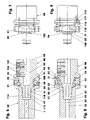
- FIG. 6 the tool holder (90) firmly clamped in the tool carrier (20) is shown. Both parts (20, 90) contact each other free of play and repeatable in the assembly joints (24) and (114) and between the fitting screws (117) and the fitting holes (25).
- the shift lever element (60) is pressed firmly against the rear grip webs (105, 106) via the eccentric shaft (51) with its projections (83, 84), under an elastic intrinsic deformation, cf.
- FIG. 7 In the transverse bore (68) is thereby the adjustment surface (46) of the eccentric pin (55) in the left bore area.
- the end faces of the projections (83, 84) are flat against the rear grip webs (105, 106).
- the tension lever element (60) thus has the effect of a spring element which generates the clamping force of the interface.
- the spring force and the associated deformability are made possible by the special geometric design of the tension lever element (60).
- the eccentric shaft (51) is pivoted about its tool recess (57), for example, 185 degrees about its center line (56) in a counterclockwise rotation, cf. FIG. 8 ,
- the pivoting is deliberately limited by the shape of the partial ring groove (53), cf. FIGS. 20 and 21 ,
- the marking (48) of the eccentric shaft (51) is now facing the tool holder (90).
- In the transverse bore (68) now comes the adjustment surface (46) of the eccentric pin (55) only in the right bore area to the plant.
- the shift lever element (60) inevitably tilts to about 3.2 degrees to the right, wherein the pivot point of the pivoting movement is approximately in the center of the bearing pin (41) of the special countersunk screw (40).
- the projections (83, 84) of the rear grip webs (105, 106) have been solved.
- the ejection tabs (77, 78) have been applied to the flat ejection surface (96) of the tool holder (90) and moved centrically to the right by approximately 0.32 mm.
- the already pre-dissolved tool holder (90) is pulled by the operator, axially with only little effort, to the right, cf. FIGS. 10 and 11 .
- the shift lever member (60) pivots to the right by another approximately 4.3 degrees, so that the planes of the end surfaces of the projections (81-84) at an angle of, for example, 7.5 degrees to their from the FIGS. 6 and 7 take known position.
- the pivotal movement is created by the engagement of the rear grip webs (105, 106) on the projections (83, 84).
- the tilting movement of the shift lever member (60) is limited by striking the left portion of the transverse bore (68) on the stop surface (47) of the eccentric pin (55).
- the angled end regions of the ejection tabs (77, 78) also move in the direction of the ejection surface (96), but without contacting them due to the surface angulations.
- the tool holder (90) is pivoted by the operator 90 degrees to the right or left about its center line (99), so that the rear webs (105, 106) in the shift lever element (60) the two gaps between the inner webs (71, 72) can happen.
- the tool holder (90) can now be easily removed from the tool carrier (20).
- the insertion of the tool holder (90) in the tool carrier (20) takes place in the reverse order.
- the tool holder (90) is pushed into the tool carrier (20) until it stops, so that the rear grip webs (105, 106) pass between the inner webs (71, 72) behind the latter.
- the marking (48) of the eccentric shaft (51) faces the tool holder (90).
- the tool holder (90) is pivoted by approximately 90 degrees to the right or left and thereby pressed axially so that the heads (118) of the fitting screws (117) slide into the fitting holes (25). He now holds with play - but captive - in the recess (30).
- the eccentric shaft (51) is pivoted by 185 degrees to the right with a hexagon wrench. As soon as the eccentric shaft (51) has been pivoted by 180 degrees, the clamping force of the tensioning mechanism has reached its maximum. Upon further rotation by 5 more degrees, only then contacted the Colourringnutauslauf (54) of the eccentric shaft (51) the pivot stopper pin (58), the clamping force drops slightly again, because the adjustment surface (46) has exceeded its dead center.
- the eccentric shaft (51) in the transverse bore (38) in a stable, self-locking position.
- the transverse bore (68) is correspondingly offset by 0.07 mm from the center line (89) arranged.
- the two projections (83, 84) By pivoting the eccentric shaft, the two projections (83, 84) at the same time to the rear grip webs (105, 106) and pull uniformly and without any tilting the mounting joints (94).
- the tool holder (90) sits now backlash-free and repeatable in the tool carrier (20).
- the fitting screws (117) seated in the fitting bores (25) center the parts (20, 90) circumferentially against each other and transversely to the center line (99).
Abstract
Description
Die Erfindung betrifft eine Schnittstelle aus einer ersten ein Bearbeitungselement haltenden Baugruppe und einer zweiten - das Bearbeitungselement tragenden oder aufweisenden - Baugruppe, wobei das Bearbeitungselement ein Werkzeug oder ein Werkzeughalter mit eingesetztem Werkzeug ist. Die erste Baugruppe weist eine in axialer Richtung - in Richtung der zweiten Baugruppe - wirkende Anlagefläche oder eine Gruppe aus mindestens drei in einer Ebene liegende Kontaktstellen auf. Die zweite Baugruppe hat mindestens eine in axialer Richtung - in Richtung der ersten Baugruppe - wirkende Anlagefläche oder eine Gruppe aus mindestens drei in einer Ebene liegende Kontaktstellen, zur Kontaktierung der Anlagefläche oder der korrespondieren Kontaktstellen der ersten Baugruppe.The invention relates to an interface comprising a first assembly holding a processing element and a second - the processing element bearing or having - assembly, wherein the processing element is a tool or a tool holder with inserted tool. The first subassembly has a contact surface acting in the axial direction - in the direction of the second subassembly - or a group of at least three contact points lying in one plane. The second subassembly has at least one abutment surface acting in the axial direction - in the direction of the first subassembly - or a group of at least three contact points lying in one plane, for contacting the contact surface or the corresponding contact points of the first subassembly.
Aus der
Der vorliegenden Erfindung liegt das Problem zugrunde, eine Schnittstelle aus einer ersten Baugruppe und einer zweiten Baugruppe zu entwickeln, die bei jedem Werkzeugwechsel außermittig belasteter Werkzeuge eine einfache Handhabung bei einer hohen Wiederholgenauigkeit bezüglich der Position der zweiten Baugruppe gegenüber der ersten Baugruppe gewährleistet.The present invention is based on the problem of developing an interface of a first module and a second module, which ensures easy handling with a high repeatability with respect to the position of the second module relative to the first module with each tool change off-center loaded tools.
Das Problem wird mit den Merkmalen des Anspruchs 1 gelöst. Dazu wird die durch die plane Montagefuge gebildete Ebene mindestens von zwei Vollstrukturen geschnitten, die in entsprechende Hohlstrukturen, mit denen sie jeweils ein Strukturpaar bilden, eingreifen. Es ist jeweils die Voll- oder die Hohlstruktur eines Strukturpaares in der ersten oder der zweiten Baugruppe angeordnet. Bei der Verwendung von zwei Strukturpaaren hat höchstens ein Strukturpaar ein Strukturpaarteil mit nur einem Freiheitsgrad, dessen Richtung gegenüber der Mittellinie des Werkzeugträgers in Radialrichtung orientiert ist oder von dieser um bis zu ± 45 Winkelgrade abweicht. Bei der Verwendung von drei und mehr Strukturpaaren weist mindestens eines oder alle Strukturpaare keinen Freiheitsgrad auf. Alternativ weist bei der Verwendung von drei und mehr Strukturpaaren je ein Strukturpaarteil einen Freiheitsgrad auf, der gegenüber der Mittellinie des Werkzeugträgers in Radialrichtung orientiert ist, oder von dieser um bis zu ± 45 Winkelgrade abweicht. Alternativ weist ferner bei der Verwendung von drei und mehr Strukturpaaren je ein Strukturpaarteil einen Freiheitsgrad auf, wobei mindestens zwei Freiheitsgrade unterschiedliche Richtungen haben. Bei drei und mehr als drei auf einem Teilkreis äquidistant verteilt gelegenen Strukturpaaren ist mindestens eine Vollstruktur weglassbar. Bei zwei und mehr als zwei in der planen Montagefuge gelegenen Strukturpaaren bilden mindestens zwei Strukturpaare eine Gruppe, die in mindestens zwei Positionen wechselweise anordenbar sind.The problem is solved with the features of
Mit der Erfindung wird eine zweite Baugruppe gegenüber einer ersten Baugruppe verdrehsicher positioniert und wiederholgenau eingespannt. Dazu ist zwischen beiden - eine Schnittstelle bildende - Baugruppen als Zwischenelement ein Schalthebelelement eingebaut. Das Schalthebelelement ist in der ersten Baugruppe schwenk- und/oder längsverschiebbar gelagert. Es weist als Anlenkelemente für die zweite Baugruppe z.B. mehrere Innenstege auf. Die zweite Baugruppe hat entsprechende stegartige Hintergriffselemente. Letztere hintergreifen beim Einsetzen der zweiten Baugruppe in die erste die Anlenkelemente des Schalthebelelements. Das Hintergreifen der Anlenkelemente durch die Hintergriffselemente kann mit dem Hintergreifen eines herkömmlichen Bajonettverschlusses verglichen werden.With the invention, a second module with respect to a first module is positioned against rotation and clamped repeatable. For this purpose, a shift lever element is installed between the two components forming an interface as an intermediate element. The shift lever element is mounted in the first assembly pivot and / or longitudinally displaceable. It has as coupling elements for the second module, for example, a plurality of inner webs. The second module has corresponding web-like engagement elements. The latter engage behind the coupling elements of the shift lever element when inserting the second module into the first. The engaging behind the coupling elements through the rear grip elements can be compared with the engaging behind a conventional bayonet closure.
In den Ausführungsbeispielen ist die erste Baugruppe ein Werkzeugträger, der z.B. in einem rotierenden Spindelkopf eines Werkzeugwechselaggregats auswechselbar angeordnet ist. Der Werkzeugträger kann z.B. ein VDI-Adapter nach DIN 69880, ein SK-Adapater nach DIN 69871 oder ein HSK-Adapter Form A+C nach ISO 12164 sein. Die zweite Baugruppe stellt in der Regel einen werkzeugtragenden Werkzeughalter dar oder nur ein Werkzeug, das direkt an der ersten Baugruppe adaptierbar ist. Die hier vorzugsweise zu spannenden Werkzeuge werden durch Schnittkräfte belastet, die exzentrisch zur Mittellinie des jeweiligen Werkzeughalters wirken. Um diese Schnittkräfte effektiv abstützen zu können, sind u.a. zur Verdrehsicherung zwischen dem Werkzeugträger und dem Werkzeughalter mindestens zwei Strukturpaare angeordnet. Diese Strukturpaare verhindern nahezu spielfrei und wiederholgenau jede Relativbewegung zwischen dem Werkzeugträger und dem Werkzeughalter, die quer zur Axialrichtung orientiert ist.In the embodiments, the first assembly is a tool carrier, e.g. is arranged exchangeably in a rotating spindle head of a tool changing unit. The tool carrier may e.g. a VDI adapter to DIN 69880, an SK adapter to DIN 69871 or a HSK adapter form A + C to ISO 12164. The second assembly usually represents a tool-carrying tool holder or just a tool that is directly adaptable to the first assembly. The here preferably to exciting tools are loaded by cutting forces acting eccentrically to the center line of the respective tool holder. In order to support these cutting forces effectively, u.a. arranged to prevent rotation between the tool carrier and the tool holder at least two structure pairs. These pairs of structures prevent almost any play and repeat exactly any relative movement between the tool carrier and the tool holder, which is oriented transversely to the axial direction.
Selbstverständlich kann die erste Baugruppe auch ein nicht rotierender Werkzeugträger sein, wie er als Stahlhalter eines Oberschlittens einer konventionellen Drehmaschine verwendet wird. Die zweite Baugruppe ist in diesem Fall der in einem Werkzeughalter angeordnete Drehstahl als Werkzeug oder Schneidenträger.Of course, the first assembly may also be a non-rotating tool carrier as used as a steel holder of a top slide of a conventional lathe. The second assembly is in this case arranged in a tool holder turning tool as a tool or cutter carrier.
Weitere Einzelheiten der Erfindung ergeben sich aus den Unteransprüchen und der nachfolgenden Beschreibung einer schematisch dargestellten Ausführungsform.
- Figur 1:
- Perspektivische Ansicht eines Werkzeugträgers und eines Werkzeughalters mit montiertem Werkzeug;
- Figur 2:
- Perspektivische Ansicht eines Werkzeugträgers und eines Werkzeugs;
- Figur 3:
- Perspektivische Vorderansicht des Werkzeugträgers;
- Figur 4:
- Perspektivische Ansicht des Schalthebelelements mit der Exzenterschraube und der Spezialsenkschraube;
- Figur 5:
- Perspektivische Rückansicht des Werkzeughalters;
- Figur 6:
- Längsschnitt zu
Figur 1 - Figur 7:
- Seitenansicht des Werkzeughalters mit der Schalthebelmechanik in Spannstellung;
- Figur 8:
- wie
Figur 6 , jedoch mit einer um 180° geschwenkten Exzenterwelle der Schalthebelmechanik; - Figur 9:
- Seitenansicht des Werkzeughalters zu
Figur 8 mit einem gegenüber der Ansicht um 45° geschwenkten Teilschnitt; - Figur 10:
- wie
Figur 8 , jedoch mit gezogenem Werkzeugadapter; - Figur 11:
- Seitenansicht des Werkzeughalters zu
Figur 10 - Figur 12:
- wie
Figur 10 - Figur 13:
- Seitenansicht des Werkzeughalters zu
Figur 12 - Figur 14:
- Radialpositionierung mit zwei Strukturpaaren ohne Freiheitsgrade;
- Figur 15:
- Radialpositionierung mit zwei Strukturpaaren mit einem Freiheitsgrad;
- Figur 16:
- Radialpositionierung mit drei Strukturpaaren ohne Freiheitsgrade;
- Figur 17:
- Radialpositionierung mit drei Strukturpaaren mit jeweils einem Freiheitsgrad;
- Figur 18:
- Radialpositionierung mit vier Strukturpaaren ohne Freiheitsgrade;
- Figur 19:
- Radialpositionierung mit vier Strukturpaaren mit jeweils einem Freiheitsgrad;
- Figur 20:
- Exzenterwelle in der Stirnansicht der Exzenterseite, vergrößert;
- Figur 21:
- Querschnitt durch die
Exzenterwelle nach Figur 20 , vergrößert; - Figur 22:
- Schalthebelelement, werkzeughalterseitige Ansicht, vergrößert;
- Figur 23:
- Seitenansicht des Schalthebelelements, vergrößert;
- Figur 24:
wie Figur 22 , jedoch werkzeugträgerseitige Ansicht, vergrößert.
- FIG. 1:
- Perspective view of a tool carrier and a tool holder with mounted tool;
- FIG. 2:
- Perspective view of a tool carrier and a tool;
- FIG. 3:
- Perspective front view of the tool carrier;
- FIG. 4:
- Perspective view of the shift lever element with the eccentric screw and the special countersunk screw;
- FIG. 5:
- Perspective rear view of the tool holder;
- FIG. 6:
- Longitudinal section too
FIG. 1 with clamped tool holder; - FIG. 7:
- Side view of the tool holder with the shift lever mechanism in clamping position;
- FIG. 8:
- as
FIG. 6 , but with a 180 ° pivoted eccentric shaft of the shift lever mechanism; - FIG. 9:
- Side view of the tool holder too
FIG. 8 with a partial section pivoted by 45 ° with respect to the view; - FIG. 10:
- as
FIG. 8 , but with drawn tool adapter; - FIG. 11:
- Side view of the tool holder too
FIG. 10 ; - FIG. 12:
- as
FIG. 10 , but with a 90 ° swiveled tool adapter; - FIG. 13:
- Side view of the tool holder too
FIG. 12 ; - FIG. 14:
- Radial positioning with two structural pairs without degrees of freedom;
- FIG. 15:
- Radial positioning with two structural pairs with one degree of freedom;
- FIG. 16:
- Radial positioning with three structural pairs without degrees of freedom;
- FIG. 17:
- Radial positioning with three structural pairs, each with one degree of freedom;
- FIG. 18:
- Radial positioning with four structural pairs without degrees of freedom;
- FIG. 19:
- Radial positioning with four structural pairs, each with one degree of freedom;
- FIG. 20:
- Eccentric shaft in the front view of the eccentric side, enlarged;
- FIG. 21:
- Cross section through the eccentric shaft after
FIG. 20 , enlarged; - FIG. 22:
- Shift lever element, tool holder side view, enlarged;
- FIG. 23:
- Side view of the shift lever element, enlarged;
- FIG. 24:
- as
FIG. 22 , but tool holder side view, enlarged.
Die
Im vorderen Bereich des Werkzeugträgers (20) befindet sich ein rohrförmiger Spanngetriebeabschnitt (21). Dieser Spanngetriebeabschnitt (21), vgl.
In der Stirn- bzw. Anlagefläche (24) sind nach
Der sich an die Anlagefläche (24) anschließende Spanngetriebeabschnitt (21) hat bei einem Werkzeugträger (20) mit z.B. 50 mm Außendurchmesser eine Tiefe von z.B. 17,2 mm, während seine Wandstärke z.B. 9 mm misst. Die Innenwandung (23) endet z.B. vor einer planen Innenstirnfläche (28), in der sich ein kegelstumpfmantelförmiger Abschnitt (31) anschließt. Dieser Abschnitt (31) hat hier z.B. einen Maximaldurchmesser von 20 mm und einen Kegelwinkel von 16 Winkelgraden. Die Länge dieses kegelstumpfmantelförmigen Abschnitts (31) beträgt ca. 14,2 mm.The tensioning gear section (21) which adjoins the contact surface (24) has, with a tool carrier (20) with e.g. 50 mm outside diameter has a depth of e.g. 17.2 mm, while its wall thickness is e.g. Measures 9 mm. The inner wall (23) ends e.g. in front of a flat inner end face (28), in which a truncated cone-shaped portion (31) adjoins. This section (31) has here, e.g. a maximum diameter of 20 mm and a cone angle of 16 degrees. The length of this truncated cone-shaped portion (31) is approximately 14.2 mm.
An den Abschnitt (31) schließt sich eine zumindest bereichsweise zylindrische Bohrung (32) an. Sie endet vor einer z.B. kegelstumpfmantelförmigen Innenstirnfläche (29), in die ggf. eine Kühl- und/oder Schmiermittelzuführbohrung (35) mündet. In der Bohrung (32) kann ein Dichtring eingesetzt werden, der die Bohrungen (32, 97) gegeneinander abdichtet.The section (31) is followed by an at least partially cylindrical bore (32). It ends before a e.g. truncated cone-shaped inner end face (29) into which, if necessary, a cooling and / or Schmiermittelzuführbohrung (35) opens. In the bore (32), a sealing ring can be used, which seals the holes (32, 97) against each other.
Der Spanngetriebeabschnitt (21) des Werkzeugträgers (20) weist z.B. zwei einander gegenüberliegende Bohrungen (36, 38) auf.The tensioning gear portion (21) of the tool carrier (20) has, for example, two opposing bores (36, 38).
Nach
In der Bohrung (38) ist nach
Die Exzenterwelle (51) hat eine glatte, zylindrische Außenfläche (52), die mit geringem Spiel oder einer Übergangspassung in einer ebenfalls glattwandigen Bohrung (38) sitzt. Im mittleren Bereich der Außenfläche (52) ist eine Teilringnut (53) eingearbeitet. Nach
Die Teilringnut (53) hat in der rechten Querschnittshälfte z.B. einen kreisabschnittförmigen Querschnitt. Der Durchmesser des zu diesem Querschnitt gehörenden Kreises beträgt z.B. 3,3 mm. Die Höhe des kreisabschnittförmigen Querschnitts misst z.B. 39% des Kreisdurchmessers.The Teilringnut (53) has in the right half of the cross section, for example, a circular section-shaped cross-section. The diameter of the circle belonging to this cross-section is for example 3.3 mm. The height of the circular segment-shaped cross section measures, for example, 39% of the circle diameter.
Um die Exzenterwelle (51) im Werkzeugträger (20) verliersicher zu halten und zugleich den Schwenkbereich der Exzenterwelle (51) zu begrenzen, befindet sich in der Stirnfläche (24) des Werkzeugträgers (20) eine Längsbohrung (27) mit M4-Gewindeabschnitt, in der ein Schwenkanschlagstift (58) eingeschraubt ist, vgl.
Die Exzenterwelle (51) hat einen nichtzylindrischen Exzenterzapfen (55), der eine aktive Verstellfläche (46) und eine passive Anschlagsfläche (47) aufweist. Dazu hat er quer zu seiner Mittellinie (56) einen unrunden Querschnitt, der sich aus zwei Kreisabschnitten zusammensetzt, die sich entlang ihrer Sehnen kontaktieren. Der Durchmesser der Kreisabschnitte beträgt z.B. 8 mm, während ihre Bogenhöhe z.B. 2,25 mm misst. Die Exzentrizität der Verstellfläche (46) beträgt z.B. 0,8 mm. Sie ist nach
Ggf. sind die Verstell- (46) und Anschlagsflächen (47) zumindest bereichsweise ballige, tonnenförmige oder sphärisch gekrümmte Außenflächen.Possibly. are the adjustment (46) and stop surfaces (47) at least partially spherical, barrel-shaped or spherically curved outer surfaces.
Die exzenterzapfenfreie Stirnseite der Exzenterwelle (51) hat eine Werkzeugausnehmung (57) mit z.B. einem sechskantförmigen Hohlquerschnitt. Zwischen der Werkzeugausnehmung (57) und der radialen Außenfläche (52) erstreckt sich eine z.B. 0,5 mm tiefe Nut (48) oder Kerbe zur Markierung der Position des Exzenterzapfens (51), vgl.
Die Werkzeugausnehmung (57) der Exzenterwelle (51) ist z.B. größer als die Werkzeugausnehmung (42) der Spezialsenkschraube (40).The tool recess (57) of the eccentric shaft (51) is e.g. larger than the tool recess (42) of the special countersunk screw (40).
In der Ausnehmung (30) steckt nach
Ggf. kann das Werkzeug (120) auch mittels eines Querpresssitzes oder dergleichen im Werkzeughalter (90) befestigt sein.Possibly. the tool (120) can also be secured in the tool holder (90) by means of a transverse press fit or the like.
Gemäß
Die Rückseite des Flanschabschnittes (91), vgl.
Ggf. können die zueinander passend bearbeiteten Anlageflächen (24) und (93) kegelstumpfmantelförmig oder sphärisch gekrümmt ausgeführt sein. Der Kegelwinkel läge dann zwischen 170 und 190 Winkelgraden, während der Krümmungsradius größer als 200 mm wäre.Possibly. the contact surfaces (24) and (93), which have been machined to fit one another, can be truncated cone-shaped or spherically curved. The cone angle would then be between 170 and 190 degrees, while the radius of curvature would be greater than 200 mm.
In der Anlagefläche (93) sind nach den
In den Gewindebohrungen (115), die hier den Flanschabschnitt (91) durchdringen, sind jeweils Passschrauben (117) eingeschraubt. Der Kopf (118) der Passschrauben (117), der fest auf dem ringförmigen Grund der Einsenkungen (116) aufliegt, ragt z.B. 1,3 mm aus den Einsenkungen (116) heraus. Der eng tolerierte Kopfdurchmesser der Passschrauben (117) beträgt z.B. 6 mm.In the threaded holes (115), which here penetrate the flange portion (91), each fitting screws (117) are screwed. The head (118) of the dowel screws (117), which rests firmly on the annular base of the depressions (116) protrudes, for example, 1.3 mm out of the depressions (116). The tightly tolerated head diameter of the fitting screws (117) is eg 6 mm.
Gegenüber dem Verriegelungsabschnitt (100) des Werkzeughalters (90) ist die Stirn- bzw. Anlagefläche (93) durch einen Wellenabsatz (95) abgetrennt. Letzterer hat eine plane Auswurffläche (96) und eine kegelstumpfmantelförmige Radialwandung. Der Kegelwinkel der Radialwandung beträgt z.B. 50 Winkelgrade. Im Bereich der Auswurffläche (96) hat der Flanschabschnitt (91) - in Axialrichtung (1) gesehen - z.B. eine geringfügig größere Wandstärke als im Bereich der Stirnfläche (93).Opposite the locking portion (100) of the tool holder (90), the front or contact surface (93) is separated by a shaft shoulder (95). The latter has a flat ejection surface (96) and a truncated cone-shaped radial wall. The cone angle of the radial wall is e.g. 50 degrees. In the region of the ejection surface (96), the flange portion (91) - viewed in the axial direction (1) - has e.g. a slightly larger wall thickness than in the region of the end face (93).
An die Auswurffläche (96) schließt sich ein kurzer zylindrischer Abschnitt (102) an, der eine Ringnut (103) mit z.B. zylindrischem Nutgrund (104) aufweist. Der Nutgrund (104) hat z.B. einen Durchmesser von 21,2 mm. Flanschseitig hat die Ringnut (103) z.B. eine kegelstumpfmantelförmige Flanke, deren Flankenwinkel 30 Winkelgrade misst. Die gegenüberliegende Nutflanke hat eine ebene Flankenfläche. Diese Flankenfläche gehört zu zwei Hintergriffsstegen (105, 106). Die Hintergriffsstege (105, 106) haben z.B. eine Wandstärke von z.B. 3 mm. Sie überdecken in Umfangsrichtung jeweils z.B. 60 Winkelgrade. Jeder Hintergriffssteg (105, 106) hat in Umfangsrichtung eine Seitenflanke, wobei die Seitenflanken (107) der Hintergriffsstege (105, 106) jeweils parallel zueinander ausgerichtet sind. Sie haben im Ausführungsbeispiel einen Abstand von 16 mm. Der maximale Durchmesser des Werkzeugträgers (20) im Bereich der Hintergriffsstege (105, 106) beträgt z.B. 25,7 mm.The ejection surface (96) is followed by a short cylindrical section (102) having an annular groove (103) with e.g. cylindrical groove bottom (104). The groove bottom (104) has e.g. a diameter of 21.2 mm. On the flange side, the annular groove (103) has e.g. a frustoconical flank whose flank angle measures 30 degrees. The opposite groove flank has a flat flank surface. This flank surface belongs to two rear grip webs (105, 106). The rearward webs (105, 106) have e.g. a wall thickness of e.g. 3 mm. They cover each other in the circumferential direction, e.g. 60 degrees. Each rear grip web (105, 106) has a side flank in the circumferential direction, wherein the side flanks (107) of the rear grip webs (105, 106) are each aligned parallel to one another. You have a distance of 16 mm in the embodiment. The maximum diameter of the tool carrier (20) in the region of the rearward webs (105, 106) is e.g. 25.7 mm.
Ggf. kann der zylindrische Abschnitt (102) durch einen Kegelstumpfmantel ersetzt werden.Possibly. For example, the cylindrical portion (102) may be replaced by a truncated cone shell.
Dem Verriegelungsabschnitt (100) ist ggf. der Zapfenabschnitt (110) nachgeschaltet. Letzterer kommt bei eingewechseltem Werkzeughalter (90) mit dem zylindrischen Endabschnitt (112) des Werkzeugträgers (20) in Kontakt. Die Kontaktfläche wird als erste Montagefuge (114) definiert. Diese Montagefuge (114), die ein radiales Spiel von mindestens 0,05 mm hat, kann auch die Form eines Kegelstumpfmantels haben, der dann großflächig am Abschnitt (31) anliegt. Je nach Ausführungsart kann der Zapfenabschnitt (110) komplett entfallen.If necessary, the journal section (110) is connected downstream of the locking section (100). The latter comes in einechselem Tool holder (90) with the cylindrical end portion (112) of the tool carrier (20) in contact. The contact surface is defined as the first assembly joint (114). This assembly joint (114), which has a radial clearance of at least 0.05 mm, can also have the shape of a truncated cone, which then over a large area on the portion (31). Depending on the embodiment, the pin portion (110) can be completely eliminated.
Innerhalb der Schnittstelle liegt gleichzeitig die hintere Stirnfläche (93) des Werkzeughalters (90) an der vorderen Stirnfläche (24) des Werkzeugträgers (20) z.B. großflächig an. Die dabei entstehende Kontaktfläche wird als zweite Montagefuge (94) bezeichnet.Within the interface, at the same time, the rear end face (93) of the tool holder (90) lies on the front end face (24) of the tool carrier (20), e.g. over a large area. The resulting contact surface is referred to as the second mounting joint (94).
Zwischen dem Spanngetriebeabschnitt (21) des Werkzeugträgers (20) und dem Verriegelungsabschnitt (100) des Werkzeughalters (90) ist das z.B. einteilige Schalthebelelement (60) angeordnet. Letzteres ist innerhalb des Werkzeugträgers (20) so orientiert, dass sein vorderer Bereich dem Werkzeughalter (90) bzw. dem Werkzeug (190) zugewandt ist.Between the tensioning gear portion (21) of the tool carrier (20) and the locking portion (100) of the tool holder (90), the e.g. one-piece shift lever element (60) is arranged. The latter is oriented within the tool carrier (20) so that its front region faces the tool holder (90) or the tool (190).
Das Schalthebelelement (60) ist ein Ring, vgl.
Die Bohrung (61) weist aus dem gleichen Grund eine Innenwandverjüngung (63) im Bereich der kleinen Querbohrung (66) auf. Hier reduziert sich die Wandstärke - im Bereich einer Lasche (76) - auf ein vergleichbares Maß. Beide Wandverjüngungen haben jeweils die Form eines Zylindermantelteils, wobei die Achse dieses Zylindermantels gegenüber der Mittellinie (89) des Schalthebelelements (60) z.B. um 7,5 Winkelgrade gekippt ist. Zwischen jeweils einer Querbohrung (66, 68) und der hinteren Stirnseite (65) des Schalthebelelements (60) ist je ein in Umfangsrichtung des Schalthebelelements ausgerichteter Steg (85, 86) angeordnet. Jeder dieser Stege (85, 86) hat eine torusteilförmig gewölbte Fläche. Über diese Fläche kontaktiert das Schalthebelelement (60) die Innenwandung (23) des Werkzeugträgers (20).The bore (61) has an inner wall taper (63) in the region of the small transverse bore (66) for the same reason. Here, the wall thickness - in the region of a tab (76) - reduced to a comparable level. Both wall tapers are each in the form of a cylinder jacket part, the axis of this cylinder jacket being opposite to the center line (89) of the shift lever element (60), e.g. tilted by 7.5 degrees. Between each of a transverse bore (66, 68) and the rear end face (65) of the shift lever element (60) each arranged in the circumferential direction of the shift lever element web (85, 86) is arranged. Each of these webs (85, 86) has a Torusteilförmig curved surface. About this surface contacted the shift lever element (60), the inner wall (23) of the tool carrier (20).
Im hinteren Bereich der Bohrung (61) sind Innenstege (71, 72) achsensymmetrisch zur Schalthebelelementmittellinie (89) angeordnet. Die Vorderflanken (73) der Innenstege (71, 72) sind kegelstumpfmantelförmige Flächen. Der Kegelwinkel beträgt hier 120 Winkelgrade. Die radialen Innenflächen (74) sind z.B. zylindrisch gewölbt. Im Bereich der Innenstege (71, 72) hat das Schalthebelelement (60) einen Durchmesser von z.B. 22,1 mm. Jeder Innensteg (71, 72) überdeckt einen Winkelbereich von z.B. 105 Winkelgraden.In the rear region of the bore (61) inner webs (71, 72) are arranged axially symmetrically to the shift lever element centerline (89). The leading edges (73) of the inner webs (71, 72) are frustoconical surfaces. The cone angle here is 120 degrees. The radial inner surfaces (74) are e.g. cylindrically curved. In the region of the inner webs (71, 72), the shift lever element (60) has a diameter of e.g. 22.1 mm. Each inner land (71, 72) covers an angular range of e.g. 105 degrees.
Beide Querbohrungen (66, 68) des Schalthebelelements (60) sind um ca. 90 Winkelgrade gegenüber den Mitten der Innenstege (71, 72) versetzt angeordnet. Nach
Ggf. können die Querbohrungen (66, 68), deren Wandungen z.B. innen gewölbt oder kegelig gekrümmt sein können, auch Ausnehmungen mit nicht kreisförmigem Querschnitt sein.Possibly. For example, the transverse bores (66, 68) whose walls are e.g. may be domed or conically curved, also be recesses with non-circular cross-section.
Die hintere Stirnfläche (65) des Schalthebelelements (60), vgl.
Zwischen den Vorsprüngen (81-84) und der zwischen diesen Vorsprüngen gelegenen Niveau der Stirnfläche (65) sind die Übergänge durch große Radien realisiert. Die z.B. 6 mm großen Radien erleichtern das Einspuren der Hintergriffselemente (105, 106) beim Einsetzen des Werkzeughalters (90).Between the projections (81-84) and the level of the end face (65) located between these projections, the transitions are realized by large radii. The e.g. 6 mm radii facilitate the meshing of the rear grip elements (105, 106) when inserting the tool holder (90).
Die vordere Stirnfläche (64), vgl.
In den
Die Passbohrungen (25) werden verallgemeinernd als Hohlstukturen (12, 13) bezeichnet. Davon gibt es zwei Arten. Die erste Art ist eine Hohlstruktur (12), die die entsprechende Vollstruktur (11) so umgibt, dass diese sowohl in Radialrichtung (2) als auch in Umfangsrichtung (3) blockiert wird, vgl.
Die zweite Art der Hohlstruktur (13) lässt der Vollstruktur (11) eine Bewegungsrichtung, z.B. die Radial- (2) oder die Umfangsrichtung (3), quer zur Axialrichtung (1) offen. Eine derartige Hohlstruktur ist z.B. eine Nut (13), in die ein Zapfen als Vollstruktur (11) eingreift, vgl.
In
Vergleichbares gilt für die Anordnung der statisch überbestimmten Strukturpaare (10) der
In
Die Anordnungen nach den
Soll nun in einen Werkzeugträger mit Hohlstrukturen (12) ein Werkzeughalter mit Vollstrukturen (11), nach
Dies ist auch möglich, wenn die Strukturpaare nicht auf einem Teilkreis liegen. In diesem Fall werden beispielsweise in der Montagefuge (94) jeweils zwei paarweise angeordnete Hohlstrukturen - als Gruppe - zwei komplementär angeordneten Vollstrukturen gegenüber positioniert. Sind nun in der Montagefuge (94) z.B. zwei weitere gruppierte Hohlstrukturen jeweils paarweise angeordnet, die jedesmal untereinander einen anderen Abstand haben, so können in dieser Montagefuge mindestens drei verschiedene Werkzeughalter an einem Werkzeugträger so positioniert werden, dass ihre Einbaulagen sicher differieren.This is also possible if the structure pairs are not on a pitch circle. In this case, for example, in the assembly joint (94) in each case two paired hollow structures - as a group - two complementary arranged full structures positioned opposite. Are now in the assembly joint (94), e.g. two further grouped hollow structures arranged in pairs, each with a different distance between them, so in this assembly joint at least three different tool holder can be positioned on a tool carrier so that their mounting positions differ safely.
Nach der Montage sitzt das Schalthebelelement (60) so im Zwischenraum zwischen dem Spanngetriebeabschnitt (21) und dem Verriegelungsabschnitt (100), dass der Lagerzapfen (41) der Spezialsenkschraube (40) in die Querbohrung (66) hineinragt, während der Exzenterzapfen (55) der Exzenterwelle (51) in die größere Querbohrung (68) hineinragt, vgl.
In
Das Spannhebelelement (60) hat somit die Wirkung eines Federelements, das die Spannkraft der Schnittstelle erzeugt. Die Federkraft und die dazugehörige Verformbarkeit werden durch die spezielle geometrische Gestaltung des Spannhebelelements (60) ermöglicht.The tension lever element (60) thus has the effect of a spring element which generates the clamping force of the interface. The spring force and the associated deformability are made possible by the special geometric design of the tension lever element (60).
Zum Lösen des Werkzeughalters (90) wird die Exzenterwelle (51) über ihre Werkzeugausnehmung (57) z.B. 185 Winkelgrade um ihre Mittellinie (56) in einer Linksdrehung geschwenkt, vgl.
Die Köpfe (118) der Passschrauben (117) stecken in dieser Lösephase noch bereichsweise in den Passbohrungen (25) des Werkzeugträgers (20).The heads (118) of the dowel screws (117) stuck in this release phase still partially in the mating holes (25) of the tool carrier (20).
In einem weiteren Schritt wird der schon vorgelöste Werkzeughalter (90) vom Bediener, axial mit nur noch geringem Kraftaufwand, nach rechts gezogen, vgl.
Durch die beschriebene Zugbewegung wird der Spalt zwischen den Anlageflächen (24) und (93) auf z.B. 1,9 mm vergrößert. Hierdurch kommen die Köpfe (118) der Passschrauben (117) frei.By the described pulling movement, the gap between the abutment surfaces (24) and (93) on e.g. 1.9 mm enlarged. As a result, the heads (118) of the fitting screws (117) come free.
In einem letzten Schritt wird der Werkzeughalter (90) vom Bediener um 90 Winkelgrade um seine Mittellinie (99) nach rechts oder links geschwenkt, damit die Hintergriffsstege (105, 106) im Schalthebelelement (60) die beiden Lücken zwischen den Innenstegen (71, 72) passieren können. Der Werkzeughalter (90) kann nun problemlos aus dem Werkzeugträger (20) entfernt werden.In a last step, the tool holder (90) is pivoted by the
Das Einsetzen des Werkzeughalters (90) in den Werkzeugträger (20) erfolgt in umgekehrter Reihenfolge. Der Werkzeughalter (90) wird bis zum Anschlagen in den Werkzeugträger (20) so eingeschoben, dass die Hintergriffsstege (105, 106) zwischen den Innenstegen (71, 72) hindurch hinter Letztere gelangen. Dabei ist die Markierung (48) der Exzenterwelle (51) dem Werkzeughalter (90) zugewandt.The insertion of the tool holder (90) in the tool carrier (20) takes place in the reverse order. The tool holder (90) is pushed into the tool carrier (20) until it stops, so that the rear grip webs (105, 106) pass between the inner webs (71, 72) behind the latter. The marking (48) of the eccentric shaft (51) faces the tool holder (90).
In einem weiteren Schritt wird der Werkzeughalter (90) um ca. 90 Winkelgrade nach rechts oder links geschwenkt und dabei axial so angedrückt, dass die Köpfe (118) der Passschrauben (117) in die Passbohrungen (25) hineinrutschen. Er hält jetzt mit Spiel - aber verliersicher - in der Ausnehmung (30). Abschließend wird die Exzenterwelle (51) mit einem Sechskantschlüssel um 185 Winkelgrade nach rechts geschwenkt. Sobald die Exzenterwelle (51) um 180 Winkelgrade verschwenkt wurde, hat die Klemmkraft der Spannmechanik ihr Maximum erreicht. Bei dem Weiterdrehen um 5 weitere Winkelgrade, erst dann kontaktiert der Teilringnutauslauf (54) der Exzenterwelle (51) den Schwenkanschlagstift (58), fällt die Klemmkraft wieder geringfügig ab, weil die Verstellfläche (46) ihren Totpunkt überschritten hat. Dadurch gelangt die Exzenterwelle (51) in der Querbohrung (38) in eine stabile, selbstsichernde Position. Um zu verhindern, dass durch die neue Exzenterzapfenlage das Schalthebelelement (60) mit seiner Mittellinie (89) von der Mittellinie (99, 39) wegwandert, ist die Querbohrung (68) gegenüber der Mittellinie (89) entsprechend um hier 0,07 mm versetzt angeordnet.In a further step, the tool holder (90) is pivoted by approximately 90 degrees to the right or left and thereby pressed axially so that the heads (118) of the fitting screws (117) slide into the fitting holes (25). He now holds with play - but captive - in the recess (30). Finally, the eccentric shaft (51) is pivoted by 185 degrees to the right with a hexagon wrench. As soon as the eccentric shaft (51) has been pivoted by 180 degrees, the clamping force of the tensioning mechanism has reached its maximum. Upon further rotation by 5 more degrees, only then contacted the Teilringnutauslauf (54) of the eccentric shaft (51) the pivot stopper pin (58), the clamping force drops slightly again, because the adjustment surface (46) has exceeded its dead center. This causes the eccentric shaft (51) in the transverse bore (38) in a stable, self-locking position. In order to prevent the switching lever element (60) from moving away from the center line (99, 39) due to the new eccentric pin position, the transverse bore (68) is correspondingly offset by 0.07 mm from the center line (89) arranged.
Durch das Verschwenken der Exzenterwelle legen sich die beiden Vorsprünge (83, 84) zeitgleich an den Hintergriffsstegen (105, 106) an und ziehen gleichförmig und ohne jedes Verkanten die Montagefugen (94) zu. Der Werkzeughalter (90) sitzt nun spielfrei und wiederholgenau im Werkzeugträger (20). Die in den Passbohrungen (25) sitzenden Passschrauben (117) zentrieren die Teile (20, 90) in Umfangsrichtung gegeneinander und quer zur Mittellinie (99).By pivoting the eccentric shaft, the two projections (83, 84) at the same time to the rear grip webs (105, 106) and pull uniformly and without any tilting the mounting joints (94). The tool holder (90) sits now backlash-free and repeatable in the tool carrier (20). The fitting screws (117) seated in the fitting bores (25) center the parts (20, 90) circumferentially against each other and transversely to the center line (99).
Ggf. können statt einer Exzenterwelle (51) und einer Spezialsenkschraube (40) auch zwei Exzenterwellen (51) verwendet werden. In diesen Fall verdoppelt sich der Gesamthub des Schalthebelelements (60).Possibly. Instead of an eccentric shaft (51) and a special countersunk screw (40), two eccentric shafts (51) can also be used. In this case, the total stroke of the shift lever member (60) doubles.
- 11
- Axialrichtungaxially
- 22
- Radialrichtung (Polarkoordinaten)Radial direction (polar coordinates)
- 33
- Umfangsrichtung (Polarkoordinaten)Circumferential direction (polar coordinates)
- 1010
- Strukturpaarstructure couple
- 1111
- Vollstrukturen, vgl. (118); Teil, StrukturpaarteilFull structures, cf. (118); Part, structural pair part
- 1212
- Hohlstrukturen, vgl. (25); Teil, StrukturpaarteilHollow structures, cf. (25); Part, structural pair part
- 1313
- Hohlstrukturen mit einem Freiheitsgrad, TeilHollow structures with one degree of freedom, part
- 1414
- Montagefuge zwischen (11) und (12)Assembly joint between (11) and (12)
- 1717
- Freiheitsgrad, transversalDegree of freedom, transversal
- 1818
- Blockierrichtungenblocking directions
- 2020
- Werkzeugträgertool carrier
- 2121
- SpanngetriebeabschnittTensioning gear section
- 2222
- Außenwandungouter wall
- 2323
- Innenwandunginner wall
- 2424
- Stirnfläche; Anlagefläche, KontaktstelleEnd face; Contact surface, contact point
- 2525
- Passbohrungen, HohlstrukturenFitting bores, hollow structures
- 2626
- Mittelliniencenterlines
- 2727
- Längsbohrung für SchwenkanschlagstiftLongitudinal bore for pivot stop pin
- 2828
- Innenstirnfläche, vornInner face, front
- 2929
- Innenstirnfläche, hintenInner face, rear
- 3030
- Ausnehmung, zentralRecess, central
- 3131
- Abschnitt, kegelstumpfmantelförmigSection, truncated cone-shaped
- 3232
- Bohrungdrilling
- 3535
- Zuführbohrung, SchmiermittelzuführbohrungFeed hole, lubricant feed hole
- 3636
- Gewindebohrung für SpezialsenkschraubeTapped hole for special countersunk screw
- 3838
- Querbohrung, zylindrischTransverse bore, cylindrical
- 3939
- Mittellinie des Werkzeugträgers, RotationsachseCenter line of the tool carrier, rotation axis
- 4040
- SpezialsenkschraubeSpezialsenkschraube
- 4141
- Lagerzapfen, ZapfenBearing journals, tenons
- 4242
- Werkzeugausnehmungtool cavity
- 4646
- Verstellflächedisplacement surface
- 4747
- Anschlagsflächestop surface
- 4848
- Nut, MarkierungGroove, marking
- 5151
- Exzenterwelleeccentric shaft
- 5252
- Außenfläche, radialOuter surface, radial
- 5353
- Teilringnutpartial annular groove
- 5454
- TeilringnutausläufeTeilringnutausläufe
- 5555
- Exzenterzapfen, ZapfenEccentric, pins
- 5656
- Mittellinie von (55)Centerline of (55)
- 5757
- Werkzeugausnehmungtool cavity
- 5858
- SchwenkanschlagstiftSwing stop pin
- 5959
- Zapfenspigot
- 6060
- Schalthebelelementlever element
- 6161
- Bohrung, großBore, big
- 6262
- AußenwandverjüngungOuter wall rejuvenation
- 6363
- InnenwandverjüngungInner wall rejuvenation
- 6464
- Stirnfläche, vornFace, front
- 6565
- Stirnfläche, hintenFace, rear
- 6666
- Querbohrung, kleinCross hole, small
- 6767
- Mittellinie zu (66)Centerline to (66)
- 6868
- Querbohrung, großCross hole, big
- 6969
- Mittellinie zu (68)Centerline to (68)
- 71, 7271, 72
- Innenstege, AnlenkelementeInner webs, hinge elements
- 7373
- Vorderflankenleading edges
- 7474
- Innenflächen, radialInner surfaces, radial
- 7575
- Anschlaglasche, vorn bei (61)Stop tab, front at (61)
- 7676
- Lasche, vorn bei (62)Flap, front at (62)
- 7777
- Ausdrücklasche, vorn bei (71)Push-out tab, front at (71)
- 7878
- Ausdrücklasche, vorn bei (72)Push-out tab, front at (72)
- 8181
- Vorsprung, hinten bei (61)Lead, rear at (61)
- 8282
- Vorsprung, hinten bei (62)Lead, rear at (62)
- 8383
- Vorsprung, hinten an (71)Ledge, rear (71)
- 8484
- Vorsprung, hinten an (72)Ledge, rear (72)
- 8585
- Steg, torusteilförmig; an (81)Bridge, torus part-shaped; on (81)
- 8686
- Steg, torusteilförmig; an (82)Bridge, torus part-shaped; on (82)
- 8989
- Mittellinie von (60)Centerline of (60)
- 9090
- Werkzeughaltertoolholder
- 9191
- Flanschabschnittflange
- 9292
- Bohrung für WerkzeugHole for tool
- 9393
- Stirnfläche, rückseitig; Anlagefläche, KontaktstelleFace, back; Contact surface, contact point
- 9494
- Montagefuge, zweiteAssembly joint, second
- 9595
- Wellenabsatzshaft shoulder
- 9696
- Auswurfflächeejector blade
- 9797
- Bohrung für SchmiermittelzufuhrBore for lubricant supply
- 9898
- Stirnfläche, vornFace, front
- 9999
- Mittelliniecenter line
- 100100
- Verriegelungsabschnittlocking section
- 102102
- Abschnitt, zylindrischSection, cylindrical
- 103103
- Ringnutring groove
- 104104
- Nutgrund, zylindrischGroove base, cylindrical
- 105, 106105, 106
- Hintergriffsstege, HintergriffselementeRear webs, rear grip elements
- 110110
- Zapfenabschnitt; Abschnitt, zylinderförmigPin portion; Section, cylindrical
- 112112
- Endabschnitt, zylindrischEnd section, cylindrical
- 114114
- Montagefuge, ersteAssembly joint, first
- 115115
- Gewindebohrungenthreaded holes
- 116116
- Einsenkungendepressions
- 117117
- PassschraubePassschraube
- 118118
- Kopf, VollstrukturenHead, full structures
- 119119
- Mittelliniencenterlines
- 120120
- Werkzeug; Schneidenträger mit SchneideTool; Cutter carrier with cutting edge
- 121121
- Schaftshaft
- 122122
- Schneide; Wendeschneidplattecutting; Indexable insert
- 125125
- Gewindebohrungenthreaded holes
- 126126
- Klemmschraubenclamping screws
- 190190
- Werkzeug, Schneidenträger mit Schneide; direkt in Werkzeugträger adaptierbarTool, blade carrier with cutting edge; directly adaptable in tool carrier
- 192192
- Schneide; Wendeschneidplattecutting; Indexable insert
Claims (9)
dadurch gekennzeichnet,
characterized,
Applications Claiming Priority (1)
| Application Number | Priority Date | Filing Date | Title |
|---|---|---|---|
| DE201210011760 DE102012011760B4 (en) | 2012-06-15 | 2012-06-15 | Modular interface for tools with cross-axial structure pairs |
Publications (1)
| Publication Number | Publication Date |
|---|---|
| EP2674236A1 true EP2674236A1 (en) | 2013-12-18 |
Family
ID=48699497
Family Applications (1)
| Application Number | Title | Priority Date | Filing Date |
|---|---|---|---|
| EP13003053.9A Withdrawn EP2674236A1 (en) | 2012-06-15 | 2013-06-14 | Modular interface for tools having structure pairs acting at right angles to the axial direction |
Country Status (2)
| Country | Link |
|---|---|
| EP (1) | EP2674236A1 (en) |
| DE (1) | DE102012011760B4 (en) |
Cited By (2)
| Publication number | Priority date | Publication date | Assignee | Title |
|---|---|---|---|---|
| EP3064300A1 (en) * | 2015-03-05 | 2016-09-07 | Benz GmbH, Werkzeugsysteme | Modular interface for rotating and rotationally fixed tools |
| CN111867763A (en) * | 2019-02-26 | 2020-10-30 | 胡贝特·基米希 | Device for fixing boring bar |
Citations (5)
| Publication number | Priority date | Publication date | Assignee | Title |
|---|---|---|---|---|
| EP0281760A2 (en) * | 1987-03-11 | 1988-09-14 | Firma Gottlieb Gühring | Coupling system for a cutting tool having a shaft |
| EP1768808B1 (en) | 2004-07-16 | 2008-04-30 | Mirko Flam | Tool adapter |
| EP2301696A1 (en) * | 2009-09-23 | 2011-03-30 | ESA Eppinger GmbH | Interface between a receiving body and an insert, the insert being particularly a tool or workpiece holder |
| DE102010044273A1 (en) * | 2010-09-02 | 2012-03-08 | Jürgen Mettchen | Tool system e.g. turning tool-adapter pair, for e.g. computerized numerical control turning machine for metal-cutting process of work piece, has adapters adapted for assembly at different machines, and tool mounted on machines by adapters |
| EP2590769A2 (en) * | 2010-07-05 | 2013-05-15 | Benz GmbH, Werkzeugsysteme | Modular interface for tools |
-
2012
- 2012-06-15 DE DE201210011760 patent/DE102012011760B4/en active Active
-
2013
- 2013-06-14 EP EP13003053.9A patent/EP2674236A1/en not_active Withdrawn
Patent Citations (5)
| Publication number | Priority date | Publication date | Assignee | Title |
|---|---|---|---|---|
| EP0281760A2 (en) * | 1987-03-11 | 1988-09-14 | Firma Gottlieb Gühring | Coupling system for a cutting tool having a shaft |
| EP1768808B1 (en) | 2004-07-16 | 2008-04-30 | Mirko Flam | Tool adapter |
| EP2301696A1 (en) * | 2009-09-23 | 2011-03-30 | ESA Eppinger GmbH | Interface between a receiving body and an insert, the insert being particularly a tool or workpiece holder |
| EP2590769A2 (en) * | 2010-07-05 | 2013-05-15 | Benz GmbH, Werkzeugsysteme | Modular interface for tools |
| DE102010044273A1 (en) * | 2010-09-02 | 2012-03-08 | Jürgen Mettchen | Tool system e.g. turning tool-adapter pair, for e.g. computerized numerical control turning machine for metal-cutting process of work piece, has adapters adapted for assembly at different machines, and tool mounted on machines by adapters |
Cited By (2)
| Publication number | Priority date | Publication date | Assignee | Title |
|---|---|---|---|---|
| EP3064300A1 (en) * | 2015-03-05 | 2016-09-07 | Benz GmbH, Werkzeugsysteme | Modular interface for rotating and rotationally fixed tools |
| CN111867763A (en) * | 2019-02-26 | 2020-10-30 | 胡贝特·基米希 | Device for fixing boring bar |
Also Published As
| Publication number | Publication date |
|---|---|
| DE102012011760B4 (en) | 2015-04-30 |
| DE102012011760A1 (en) | 2013-12-19 |
Similar Documents
| Publication | Publication Date | Title |
|---|---|---|
| EP0507147B1 (en) | Coupling | |
| DE102009060678B4 (en) | Tool carrier with a collet holder and tool insert for use in a tool carrier | |
| EP3341149B1 (en) | Cutting insert, tool holder and tool | |
| DE102010014322B4 (en) | Tool head for a rotating tool | |
| EP1044081B1 (en) | Milling head with one to three-dimensional adjustable cutting insert and with a positive fitting cutting insert | |
| DE69928744T2 (en) | milling cutter | |
| EP0674561A1 (en) | Solid drill | |
| EP1896207B1 (en) | Tool system with interface | |
| EP0284745B1 (en) | Coupling between a tool head and a tool carrier | |
| DE3433878A1 (en) | AXIAL CLAMP CONNECTION | |
| EP2646188B1 (en) | Tool assembly with eccentric clamping device | |
| WO2005077575A2 (en) | Tool for machining precision bores | |
| EP2590769B1 (en) | Modular interface for tools | |
| EP3703893B1 (en) | Milling tool holder and milling tool | |
| DE102007043953B4 (en) | Clamping device for the axial clamping of two mutually releasable machine components | |
| DE102012011760B4 (en) | Modular interface for tools with cross-axial structure pairs | |
| EP3713700A1 (en) | Tool for machining a workpiece | |
| CH668723A5 (en) | REVOLVER HEAD FOR A LATHE AND TOOL HOLDER TO MATCH THERE. | |
| EP3403758A1 (en) | Adjustable attachment adapter | |
| WO2018029013A1 (en) | Tool holder | |
| EP0285704B1 (en) | Clamping system of several parts in particular for concentric running tools | |
| EP3275597A1 (en) | Tool and method for tightening and loosening components | |
| CH499365A (en) | Chucks for tools | |
| EP3142818B1 (en) | Modular interface for tools | |
| EP3486035B1 (en) | Fixing system for fixing a tool on a tool holder and associated tool key |
Legal Events
| Date | Code | Title | Description |
|---|---|---|---|
| PUAI | Public reference made under article 153(3) epc to a published international application that has entered the european phase |
Free format text: ORIGINAL CODE: 0009012 |
|
| AK | Designated contracting states |
Kind code of ref document: A1 Designated state(s): AL AT BE BG CH CY CZ DE DK EE ES FI FR GB GR HR HU IE IS IT LI LT LU LV MC MK MT NL NO PL PT RO RS SE SI SK SM TR |
|
| AX | Request for extension of the european patent |
Extension state: BA ME |
|
| 17P | Request for examination filed |
Effective date: 20140617 |
|
| RBV | Designated contracting states (corrected) |
Designated state(s): AL AT BE BG CH CY CZ DE DK EE ES FI FR GB GR HR HU IE IS IT LI LT LU LV MC MK MT NL NO PL PT RO RS SE SI SK SM TR |
|
| STAA | Information on the status of an ep patent application or granted ep patent |
Free format text: STATUS: EXAMINATION IS IN PROGRESS |
|
| 17Q | First examination report despatched |
Effective date: 20170202 |
|
| STAA | Information on the status of an ep patent application or granted ep patent |
Free format text: STATUS: EXAMINATION IS IN PROGRESS |
|
| STAA | Information on the status of an ep patent application or granted ep patent |
Free format text: STATUS: EXAMINATION IS IN PROGRESS |
|
| GRAP | Despatch of communication of intention to grant a patent |
Free format text: ORIGINAL CODE: EPIDOSNIGR1 |
|
| STAA | Information on the status of an ep patent application or granted ep patent |
Free format text: STATUS: GRANT OF PATENT IS INTENDED |
|
| INTG | Intention to grant announced |
Effective date: 20230405 |
|
| P01 | Opt-out of the competence of the unified patent court (upc) registered |
Effective date: 20230606 |
|
| STAA | Information on the status of an ep patent application or granted ep patent |
Free format text: STATUS: THE APPLICATION IS DEEMED TO BE WITHDRAWN |
|
| 18D | Application deemed to be withdrawn |
Effective date: 20230817 |