EP2674176B1 - Device for adjusting irrigation pressure during eye operations - Google Patents
Device for adjusting irrigation pressure during eye operations Download PDFInfo
- Publication number
- EP2674176B1 EP2674176B1 EP12171667.4A EP12171667A EP2674176B1 EP 2674176 B1 EP2674176 B1 EP 2674176B1 EP 12171667 A EP12171667 A EP 12171667A EP 2674176 B1 EP2674176 B1 EP 2674176B1
- Authority
- EP
- European Patent Office
- Prior art keywords
- height
- foot switch
- fluid
- eye
- irrigation
- Prior art date
- Legal status (The legal status is an assumption and is not a legal conclusion. Google has not performed a legal analysis and makes no representation as to the accuracy of the status listed.)
- Active
Links
- 230000002262 irrigation Effects 0.000 title claims description 46
- 238000003973 irrigation Methods 0.000 title claims description 46
- 239000012530 fluid Substances 0.000 claims description 20
- 238000001356 surgical procedure Methods 0.000 claims description 12
- 239000000463 material Substances 0.000 claims 1
- 239000007788 liquid Substances 0.000 description 11
- 238000010586 diagram Methods 0.000 description 6
- 230000008901 benefit Effects 0.000 description 3
- 230000008859 change Effects 0.000 description 3
- 238000000034 method Methods 0.000 description 2
- 230000004913 activation Effects 0.000 description 1
- 239000012620 biological material Substances 0.000 description 1
- 238000004590 computer program Methods 0.000 description 1
- 238000011010 flushing procedure Methods 0.000 description 1
- 238000001802 infusion Methods 0.000 description 1
- 230000004044 response Effects 0.000 description 1
Images

Classifications
-
- A—HUMAN NECESSITIES
- A61—MEDICAL OR VETERINARY SCIENCE; HYGIENE
- A61M—DEVICES FOR INTRODUCING MEDIA INTO, OR ONTO, THE BODY; DEVICES FOR TRANSDUCING BODY MEDIA OR FOR TAKING MEDIA FROM THE BODY; DEVICES FOR PRODUCING OR ENDING SLEEP OR STUPOR
- A61M3/00—Medical syringes, e.g. enemata; Irrigators
- A61M3/02—Enemata; Irrigators
- A61M3/0233—Enemata; Irrigators characterised by liquid supply means, e.g. from pressurised reservoirs
- A61M3/0241—Enemata; Irrigators characterised by liquid supply means, e.g. from pressurised reservoirs the liquid being supplied by gravity
-
- A—HUMAN NECESSITIES
- A61—MEDICAL OR VETERINARY SCIENCE; HYGIENE
- A61F—FILTERS IMPLANTABLE INTO BLOOD VESSELS; PROSTHESES; DEVICES PROVIDING PATENCY TO, OR PREVENTING COLLAPSING OF, TUBULAR STRUCTURES OF THE BODY, e.g. STENTS; ORTHOPAEDIC, NURSING OR CONTRACEPTIVE DEVICES; FOMENTATION; TREATMENT OR PROTECTION OF EYES OR EARS; BANDAGES, DRESSINGS OR ABSORBENT PADS; FIRST-AID KITS
- A61F9/00—Methods or devices for treatment of the eyes; Devices for putting-in contact lenses; Devices to correct squinting; Apparatus to guide the blind; Protective devices for the eyes, carried on the body or in the hand
- A61F9/007—Methods or devices for eye surgery
-
- A—HUMAN NECESSITIES
- A61—MEDICAL OR VETERINARY SCIENCE; HYGIENE
- A61M—DEVICES FOR INTRODUCING MEDIA INTO, OR ONTO, THE BODY; DEVICES FOR TRANSDUCING BODY MEDIA OR FOR TAKING MEDIA FROM THE BODY; DEVICES FOR PRODUCING OR ENDING SLEEP OR STUPOR
- A61M3/00—Medical syringes, e.g. enemata; Irrigators
- A61M3/02—Enemata; Irrigators
- A61M3/0233—Enemata; Irrigators characterised by liquid supply means, e.g. from pressurised reservoirs
- A61M3/0254—Enemata; Irrigators characterised by liquid supply means, e.g. from pressurised reservoirs the liquid being pumped
-
- A—HUMAN NECESSITIES
- A61—MEDICAL OR VETERINARY SCIENCE; HYGIENE
- A61M—DEVICES FOR INTRODUCING MEDIA INTO, OR ONTO, THE BODY; DEVICES FOR TRANSDUCING BODY MEDIA OR FOR TAKING MEDIA FROM THE BODY; DEVICES FOR PRODUCING OR ENDING SLEEP OR STUPOR
- A61M1/00—Suction or pumping devices for medical purposes; Devices for carrying-off, for treatment of, or for carrying-over, body-liquids; Drainage systems
- A61M1/71—Suction drainage systems
- A61M1/77—Suction-irrigation systems
-
- A—HUMAN NECESSITIES
- A61—MEDICAL OR VETERINARY SCIENCE; HYGIENE
- A61M—DEVICES FOR INTRODUCING MEDIA INTO, OR ONTO, THE BODY; DEVICES FOR TRANSDUCING BODY MEDIA OR FOR TAKING MEDIA FROM THE BODY; DEVICES FOR PRODUCING OR ENDING SLEEP OR STUPOR
- A61M2205/00—General characteristics of the apparatus
- A61M2205/33—Controlling, regulating or measuring
- A61M2205/3331—Pressure; Flow
- A61M2205/3344—Measuring or controlling pressure at the body treatment site
-
- A—HUMAN NECESSITIES
- A61—MEDICAL OR VETERINARY SCIENCE; HYGIENE
- A61M—DEVICES FOR INTRODUCING MEDIA INTO, OR ONTO, THE BODY; DEVICES FOR TRANSDUCING BODY MEDIA OR FOR TAKING MEDIA FROM THE BODY; DEVICES FOR PRODUCING OR ENDING SLEEP OR STUPOR
- A61M2209/00—Ancillary equipment
- A61M2209/08—Supports for equipment
- A61M2209/082—Mounting brackets, arm supports for equipment
-
- A—HUMAN NECESSITIES
- A61—MEDICAL OR VETERINARY SCIENCE; HYGIENE
- A61M—DEVICES FOR INTRODUCING MEDIA INTO, OR ONTO, THE BODY; DEVICES FOR TRANSDUCING BODY MEDIA OR FOR TAKING MEDIA FROM THE BODY; DEVICES FOR PRODUCING OR ENDING SLEEP OR STUPOR
- A61M2210/00—Anatomical parts of the body
- A61M2210/06—Head
- A61M2210/0612—Eyes
-
- A—HUMAN NECESSITIES
- A61—MEDICAL OR VETERINARY SCIENCE; HYGIENE
- A61M—DEVICES FOR INTRODUCING MEDIA INTO, OR ONTO, THE BODY; DEVICES FOR TRANSDUCING BODY MEDIA OR FOR TAKING MEDIA FROM THE BODY; DEVICES FOR PRODUCING OR ENDING SLEEP OR STUPOR
- A61M3/00—Medical syringes, e.g. enemata; Irrigators
- A61M3/02—Enemata; Irrigators
- A61M3/0266—Stands, holders or storage means for irrigation devices
Definitions
- the invention relates to a device for use in ophthalmic surgery, comprising a container with fluid, which is connected via an irrigation line with a surgical handpiece for dispensing the fluid for rinsing an operated eye, wherein a particular electrically adjustable in height stand for supporting the Container and for adjusting the height between the container and surgical handpiece is provided, and wherein a controller for adjusting the height of the stand is provided to deliver the fluid with an operator prescribed Irrigationstik of the surgical handpiece in the eye.
- the document EP 1 428 541 B 1 discloses such a device that is part of an eye surgery device that allows me to insert a new lens into the eye of a patient.
- the surgeon places a cut on the eye for the time being, over which the old lens cut into small pieces is removed, and then the new lens is inserted into the eye.
- the surgical handpiece In order to facilitate the removal of the small pieces of the old lens and to prevent the volume of the eye originally occupied by the old lens from collapsing during surgery, the surgical handpiece must deliver the fluid with an irrigation pressure into the operated eye. Too high an irrigation pressure would permanently damage the eye and, if the irrigation pressure is too low, there is a risk of the eye collapsing, which is why the surgeon must be able to set the appropriate irrigation pressure.
- the height of the stand is adjustable only to a certain extent and with a particularly large incision in the eye of the required irrigation pressure can not be achieved even with maximum height of the stand. Also, it may be that the maximum adjustable with the stand Although height would be sufficient that in the operating room but due to structural limitations, such as the ceiling height, the necessary for the desired Irrigationstik height of the stand is not adjustable.
- Another device for adjusting the irrigation pressure is off US 2001/023331 A1 named.
- the invention has for its object to provide a device for use in ophthalmic surgery, which ensures the surgeon greater flexibility and safety to adjust the required for eye surgery and sanitary irrigation pressure of the fluid in the eye.
- the invention is defined by the features of independent claim 1. According to the invention, this task is accomplished by providing pressurizing means adapted to apply the atmospheric pressure fluid to the irrigation line from the container, and in that the controller sets the desired irrigation pressure to both adjust the height of the stand and adjust is formed to be acted upon atmospheric pressure.
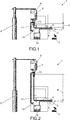
- FIG. 1 shows a device for use in ophthalmic surgery.
- FIG. 2 shows the device according to FIG. 1 , wherein the height of the stand of the container has been changed.
- FIG. 3 shows how the control of the device according to FIG. 1 with a footswitch preset irrigation pressure.
- FIG. 1 shows a device 1 for use in ophthalmic surgery, which is part of a in FIG. 1 not shown eye surgery device forms.
- a new lens 2 can be inserted into an eye 3 of a patient.
- a cut is made on the eye 3 by the surgeon during the operation.
- FIG. 1 not shown surgical handpiece fulfills three functions during the operation.
- fluid or rinsing fluid 5 is dispensed into the eye 3 for rinsing the eye 3 of the surgical handpiece with an irrigation pressure predetermined by the surgeon.
- a piezo-driven knife provided in the surgical handpiece divided the old lens 2 into small pieces which are sucked together with the rinsing liquid 5 through an aspiration port 6 of the handpiece and collected in a cassette 14 of the ophthalmic surgical device.
- the rinsing liquid 5 having a certain predetermined irrigation pressure has to be inserted into the surgical handpiece operated eye 3 are delivered. Too high an irrigation pressure would permanently damage the eye 3 and, if the irrigation pressure is too low, there is a risk of collapse of the eye 3, which is why the surgeon must set the appropriate irrigation pressure. It is crucial here how well the operator succeeds in the planned length of the incision on the eye at the beginning of the operation, since this influences the volume of the rinsing liquid 5 per unit of time for rinsing the eye 3.
- the device 1 now has a foot switch 7, with which the surgeon can specify both the currently desired irrigation pressure and the currently desired negative pressure at the aspiration opening 6 for aspiration.
- the device 1 further comprises a controller not shown in the figures, implemented by a computer including computer program of the device 1, which, as described below, both the predetermined irrigation pressure at the irrigation port 4 and sets the predetermined negative pressure at the aspiration opening 6.
- the device 1 now has to set the irrigation pressure both an electrically adjustable in height stand 8 for the container 9 of the rinsing liquid 5, as well as pressurizing means 10, the via a pressure line 11 an atmospheric pressure on a surface 13 of the irrigation line 12 to be dispensed rinsing liquid 5 apply.
- the controller drives the electric motor of the stator 8 to adjust a certain height H of the liquid column from the container 9 to the irrigation port 4 of the surgical handpiece.
- the height H of the liquid column influences the irrigation pressure at the irrigation port 4.
- the pressurizing means 10 formed by an electric compressed air pump pump compressed air to the surface 13 of the liquid column with an atmospheric pressure predetermined by the controller, thereby further increasing the irrigation pressure.
- FIG. 3 There are four diagrams showing how the controller meets these requirements.
- the top diagram shows a possible actuation B of the foot switch 7 over time t. Up to a time t 1 , the surgeon does not actuate the foot switch and starts from this time t 1 to press the foot switch 7 more and more until he t 2 the foot switch 7 at 50% and at a time t 3 entirely, ie to 100%, squeezed. From a time t 4 to a time t 5 , the surgeon presses ever weaker on the foot switch. 7
- the predetermined by the operator due to the operation B of the foot switch 7 by the surgeon atmospheric pressure P ATÜ is represented by the pressurizing means 10 according to a first embodiment.
- a pressure of 50 mmHg is already applied by the pressurizing means 10 via the pressure line 11 to the surface 13 of the rinsing liquid 5 to be dispensed to the irrigation line 12.
- This atmospheric pressure P ATÜ is maintained by the controller as long as the operation B of the foot switch is more than 1%.
- the control according to the invention for setting the desired irrigation pressure by adjusting the height H of the upright 8 as well as pressurizing the surface 13 with the atmospheric overpressure P ATÜ has the advantage that a certain minimum irrigation pressure is present by applying the atmospheric overpressure P ATÜ , which can be easily and reliably adjusted by means of the simple and immediately effective height adjustment of the stand 8 and also tracked.
- a certain minimum irrigation pressure is present by applying the atmospheric overpressure P ATÜ , which can be easily and reliably adjusted by means of the simple and immediately effective height adjustment of the stand 8 and also tracked.
- only a small additional pressure increase by a small change in the height of the stator 8 is required.
- structural restrictions in the operating room can not influence the structure of the required irrigation pressure.
- one or more stages may be fixed at certain predetermined percentages of the operation B of the foot switch 7 by the controller.
- the person skilled in the art can determine the best composition of these partial pressures by atmospheric pressure P ATÜ and height adjustment according to the invention. In this case, different embodiments of the method for controlling the device 1 can be realized.
- control initially adjusts the height of the stand when the foot switch is actuated, and then further increases the irrigation pressure by means of the pressurizing means upon stronger activation of the foot switch. It would also be possible to do this alternately or in a different predetermined order.
- electrically operated or controlled functions can also be replaced by pneumatically operated or controlled functions.
- the pressurizing means could also be driven via a compressed air wall or a compressed air cylinder instead of the electric compressed air pump.
Description
Die Erfindung betrifft eine Vorrichtung zur Verwendung in der Augenchirurgie, die einen Behälter mit Fluid aufweist, der über eine Irrigationsleitung mit einem chirurgischen Handstück zum Abgeben des Fluids zum Spülen eines operierten Auges verbunden ist, wobei ein insbesondere elektrisch in seiner Höhe verstellbarer Ständer zum Tragen des Behälters und zum Verstellen der Höhe zwischen Behälter und chirurgischem Handstück vorgesehen ist, und wobei eine Steuerung zum Verstellen der Höhe des Ständers vorgesehen ist, um das Fluid mit einem vom Operateur vorgegebenen Irrigationsdruck von dem chirurgischen Handstück in das Auge abzugeben.The invention relates to a device for use in ophthalmic surgery, comprising a container with fluid, which is connected via an irrigation line with a surgical handpiece for dispensing the fluid for rinsing an operated eye, wherein a particular electrically adjustable in height stand for supporting the Container and for adjusting the height between the container and surgical handpiece is provided, and wherein a controller for adjusting the height of the stand is provided to deliver the fluid with an operator prescribed Irrigationsdruck of the surgical handpiece in the eye.
Das Dokument
Bei der bekannten Vorrichtung hat sich als Nachteil ergeben, dass die Höhe des Ständers nur in einem bestimmten Ausmaß einstellbar ist und bei einem besonders großen Schnitt im Auge der erforderliche Irrigationsdruck auch mit maximaler Höhe des Ständers nicht erreicht werden kann. Auch kann es sein, dass die maximal mit dem Ständer einstellbare Höhe zwar ausreichen würde, dass in dem Operationssaal aber durch bauliche Beschränkungen, wie beispielsweise der Raumhöhe, die für den gewünschten Irrigationsdruck nötige Höhe des Ständers nicht einstellbar ist. Eine weitere Vorrichtung zur Einstellung des Irrigationsdruckes ist aus
Der Erfindung liegt die Aufgabe zugrunde eine Vorrichtung zur Verwendung in der Augenchirurgie zu schaffen, die dem Operateur größere Flexibilität und Sicherheit gewährleistet den für die Augenoperation nötigen und gesundheitlich unbedenklichen Irrigationsdruck des Fluids im Auge einzustellen.The invention has for its object to provide a device for use in ophthalmic surgery, which ensures the surgeon greater flexibility and safety to adjust the required for eye surgery and sanitary irrigation pressure of the fluid in the eye.
Die Erfindung wird durch die Merkmale des unabhängigen Anspruchs 1 definiert. Erfindungsgemäß wird diese Aufgabestellung dadurch gelöst, dass Druckbeaufschlagungsmittel vorgesehen sind, die zum Beaufschlagen des an die Irrigationsleitung von dem Behälter abzugebenden Fluids mit einem Atmosphärenüberdruck ausgebildet sind, und dass die Steuerung zum Einstellen des gewünschten Irrigationsdrucks sowohl zum Verstellen der Höhe des Ständers als auch zum Einstellen des zu beaufschlagenden Atmosphärenüberdrucks ausgebildet ist.The invention is defined by the features of
Hierdurch ist der Vorteil erhalten, dass ein gewisser minimal für die Operation auf jeden Fall nötiger Irrigationsdruck des Fluids durch Beaufschlagen des Atmosphärenüberdrucks auf das Fluid mittels der Druckbeaufschlagungsmittel erreicht wird. Die Feineinstellung beziehungsweise endgültige Einstellung des gewünschten Irrigationsdrucks erfolgt durch die Steuerung durch Einstellung der Höhe des Ständers. Da ein einmal beaufschlagter Atmosphärenüberdruck nur durch das langsam abfließende Fluid oder mittels eines relativ teuren Infusionsbestecks wieder reduziert werden kann, ergibt dieser gestaffelte Aufbau des Irrigationsdrucks den Vorteil, dass durch Beaufschlagung des Atmosphärenüberdrucks ein gewisser minimaler Irrigationsdruck vorhanden ist, der mittels der einfachen und unmittelbar wirksamen Höheneinstellung des Ständers gut und zuverlässig einjustiert und auch nachgeführt werden kann.Thereby, the advantage is obtained that a certain minimum required for the operation in any case Irrigationsdruck the fluid is achieved by applying the atmospheric pressure to the fluid by means of the pressurizing means. The fine adjustment or final adjustment of the desired irrigation pressure is carried out by the controller by adjusting the height of the stand. Since an atmospheric overpressure which has once been applied can be reduced again only by the slowly draining off fluid or by means of a relatively expensive infusion set, this staggered structure of the irrigation pressure has the advantage that, by acting on the atmospheric overpressure, a certain minimum irrigation pressure is present which can be achieved by means of the simple and immediately effective Height adjustment of the stand can be adjusted well and reliably and also tracked.
Weitere vorteilhafte Ausgestaltungen des erfindungsgemäßen Systems werden im Folgenden anhand der Figuren näher erläutert.Further advantageous embodiments of the system according to the invention are explained in more detail below with reference to FIGS.
Ein in
Um das Entfernen der kleinen Stücke der alten Linse 2 zu ermöglichen und um zu verhindern, dass das von der alten Linse 2 ursprünglich eingenommene Volumen im Auge 3 bei der Operation kollabiert, muss von dem chirurgischen Handstück die Spülflüssigkeit 5 mit einem bestimmten vorgegebenem Irrigationsdruck in das operierte Auge 3 abgegeben werden. Ein zu hoher Irrigationsdruck würde das Auge 3 bleibend schädigen und bei einem zu geringen Irrigationsdruck ist die Gefahr des Kollabierens des Auges 3 gegeben, weshalb der Operateur den geeigneten Irrigationsdruck einstellen muss. Hierbei ist entscheidend, wie gut dem Operateur am Beginn der Operation die geplante Länge des Schnitts an dem Auge gelingt, da diese das Volumen der Spülflüssigkeit 5 je Zeiteinheit zum Spülen des Auges 3 beeinflusst.In order to enable the removal of the small pieces of the
Die Vorrichtung 1 weist nunmehr eine Fußschalter 7 auf, mit dem der Operateur sowohl den momentan gewünschten Irrigationsdruck als auch den momentan gewünschten Unterdruck an der Aspirationsöffnung 6 zum Absaugen vorgeben kann. Die Vorrichtung 1 weist weiters eine in den Figuren nicht näher dargestellte, durch einen Computer samt Computerprogramm der Vorrichtung 1 realisierte Steuerung auf, die, wie nachfolgend beschrieben, sowohl den vorgegebenen Irrigationsdruck an der Irrigationsöffnung 4 als auch den vorgegebenen Unterdruck an der Aspirationsöffnung 6 einstellt.The
Die Vorrichtung 1 weist nunmehr zum Einstellen des Irrigationsdrucks sowohl einen in seiner Höhe elektrisch verstellbaren Ständer 8 für den Behälter 9 der Spülflüssigkeit 5, als auch Druckbeaufschlagungsmittel 10 auf, die über eine Druckleitung 11 einen Atmosphärenüberdruck auf eine Oberfläche 13 der an die Irrigationsleitung 12 abzugebenden Spülflüssigkeit 5 beaufschlagen. Die Steuerung steuert den Elektromotor des Ständers 8 an, um eine bestimmte Höhe H der Flüssigkeitssäule von dem Behälter 9 zu der Irrigationsöffnung 4 des chirurgischen Handstücks einzustellen. Die Höhe H der Flüssigkeitssäule beeinflusst den Irrigationsdruck an der Irrigationsöffnung 4. Die durch eine elektrische Druckluftpumpe gebildeten Druckbeaufschlagungsmittel 10 pumpen Druckluft mit einem von der Steuerung vorgegebenem Atmosphärenüberdruck auf die Oberfläche 13 der Flüssigkeitssäule, wodurch der Irrigationsdruck zusätzlich erhöht wird.The
In
In einem darunter dargestellten Diagramm ist der von der Steuerung auf Grund der Betätigung B des Fußschalters 7 durch den Operateur vorgegebene Atmosphärenüberdruck PATÜ durch die Druckbeaufschlagungsmittel 10 gemäß einem ersten Ausführungsbeispiel dargestellt. Gemäß diesem Ausführungsbeispiel wird bereits bei einem leichten Betätigen des Fußschalters 7 ab bereits 1% Betätigung B ein Druck von 50 mmHg von den Druckbeaufschlagungsmitteln 10 über die Druckleitung 11 an die Oberfläche 13 der an die Irrigationsleitung 12 abzugebenden Spülflüssigkeit 5 beaufschlagt. Dieser Atmosphärenüberdruck PATÜ wird von der Steuerung so lange aufrecht erhalten, so lange die Betätigung B des Fußschalters mehr als 1% beträgt.In a diagram shown below, the predetermined by the operator due to the operation B of the
In einem darunter dargestellten Diagramm ist die Verstellung der Höhe H zwischen der Oberfläche 13 in dem Behälter 9 und der Irrigationsöffnung 4 des chirurgischen Handstücks durch die Steuerung in Abhängigkeit der Betätigung B des Fußschalters 7 durch den Operateur dargestellt. Zu dem Zeitpunkt t3 bei einer Betätigung des Fußschalters von 50% steuert die Steuerung den elektrisch verstellbaren Ständer 8 von der Höhe von H = 0cm auf die Höhe H = 65cm. Eine Höhe H = 100cm Flüssigkeitssäule entspricht etwa dem Druck von 73,5 mmHg, weshalb sich der Irrigationsdruck der Spülflüssigkeit an der Irrigationsöffnung 4 ab den Zeitpunkt t3 aus 50 mmHg + 48 mmHg zu insgesamt 98 mmHg zusammensetzt. Dieser durch die Betätigung B des Fußschalters 7 durch den Operateur vorgegebene Irrigationsdruck wird von der Steuerung so lange aufrecht erhalten, bis der Operateur den Fußschalter 7 wieder weniger stark als 50% betätigt. Hierfür reduziert die Steuerung die Höhe H des Ständers 8.In a diagram shown below, the adjustment of the height H between the
In dem untersten Diagramm in
Durch die erfindungsgemäße Steuerung zum Einstellen des gewünschten Irrigationsdrucks durch sowohl das Verstellen der Höhe H des Ständers 8 als auch durch das Beaufschlagenden der Oberfläche 13 mit dem Atmosphärenüberdruck PATÜ ist der Vorteil erhalten, dass durch Beaufschlagung des Atmosphärenüberdrucks PATÜ ein gewisser minimaler Irrigationsdruck vorhanden ist, der mittels der einfachen und unmittelbar wirksamen Höheneinstellung des Ständers 8 gut und zuverlässig einjustiert und auch nachgeführt werden kann. Je nach dem, welcher Atmosphärenüberdruck von der Steuerung vorgegeben wird, ist nur mehr eine geringe zusätzlich Druckerhöhung durch eine geringe Änderung der Höhe des Ständers 8 nötig. Hierdurch können auch bauliche Einschränkungen in dem Operationssaal den Aufbau des erforderlichen Irrigationsdrucks nicht beeinflussen.The control according to the invention for setting the desired irrigation pressure by adjusting the height H of the upright 8 as well as pressurizing the
Für den Operateur ist besonders wichtig, dass während der Operation gemäß seinen durch den Fußschalter 7 festgelegten Vorgaben die drei Funktionen des chirurgischen Handstücks zuverlässig und nachvollziehbar von der Steuerung eingestellt werden. Ein ständiges Ändern der Höhe H des Ständers 8 bei beliebig kleinen Änderungen der Betätigung B des Fußschalters 7 wäre folglich sehr störend. Es hat sich somit als vorteilhaft erwiesen den Irrigationsdruck nur durch stufenweises Erhöhen der Höhe H des Ständers 8 zu verändern, da sich der Operateur, abgesehen von den Zeitbereichen, wenn der Ständer gerade seine Höhe H ändert, auf gleichmäßige Druckverhältnisse einstellen kann, was die Operation wesentlich erleichtert.It is particularly important for the surgeon that the three functions of the surgical handpiece are reliably and comprehensibly adjusted by the controller during the operation in accordance with his specifications established by the
Je nach Ausführungsbeispiel können ein oder mehrere Stufen (Vergrößerung der Höhe H des Ständers 8) bei bestimmten vorgegebenen Prozentsätzen der Betätigung B des Fußschalters 7 durch die Steuerung festgelegt sein. Ebenso könnten auch die Druckbeaufschlagungsmittel 10 vorerst nur z.B. 30 mmHg Atmosphärenüberdruck PATÜ bei z.B. B = 5% anlegen und dem Operateur so einen größeren Regelbereich mit dem Fußschalter 7 durch die Verstellung der Höhe des Ständers 8 geben. Je nach Anwendungsfall kann der Fachmann entsprechend der Erfindung die beste Zusammensetzung dieser Partialdrücke durch Atmosphärenüberdruck PATÜ und Höhenverstellung festlegen. Hierbei sind unterschiedliche Ausgestaltungen des Verfahrens zur Steuerung der Vorrichtung 1 realisierbar.Depending on the embodiment, one or more stages (increase in the height H of the stator 8) may be fixed at certain predetermined percentages of the operation B of the
Es kann erwähnt werden, dass es bei manchen Anwendungsbeispielen auch vorteilhaft sein kann, wenn die Steuerung bei Betätigung des Fußschalters vorerst die Höhe des Ständers verstellt und erste dann mittels der Druckbeaufschlagungsmittel bei stärkerer Betätigung des Fußschalters den Irrigationsdruck weiter erhöht. Auch wäre es möglich dies abwechselnd oder in einer anderen vorgegebenen Reihenfolge durchzuführen.It may be mentioned that in some application examples it may also be advantageous if the control initially adjusts the height of the stand when the foot switch is actuated, and then further increases the irrigation pressure by means of the pressurizing means upon stronger activation of the foot switch. It would also be possible to do this alternately or in a different predetermined order.
Die in der Tabelle gemäß Anspruch 4 angegebenen Werte haben sich in der Praxis als besonders vorteilhaft erwiesen, um eine gute Operation der Linse des Auges zu ermöglichen.The values given in the table according to
Es kann erwähnt werden, dass in vorstehendem Ausführungsbeispiel elektrisch betriebene oder gesteuerte Funktionen auch durch pneumatisch betriebene oder gesteuerte Funktionen ersetzt werden können. So könnten beispielsweise die Druckbeaufschlagungsmittel anstatt der elektrischen Druckluftpumpe auch über eine Druckluftwand oder einen Druckluftzylinder angetrieben werden.It may be mentioned that in the above exemplary embodiment electrically operated or controlled functions can also be replaced by pneumatically operated or controlled functions. Thus, for example, the pressurizing means could also be driven via a compressed air wall or a compressed air cylinder instead of the electric compressed air pump.
Claims (4)
- A device (1) for use in eye surgery, comprising a container (9) with fluid (5) which is connected via an irrigation line (12) to a surgical handpiece for delivering the fluid (5) for rinsing an eye (3) on which surgery has been performed, wherein a pillar (8), which is electrically adjustable in its height, is provided for supporting the container (9) and for adjusting the height (H) between the container (9) and the surgical handpiece, and wherein a control for adjusting the height of the pillar (8) is provided in order to deliver the fluid (5) from the surgical handpiece into the eye (3) at an irrigation pressure predetermined by the surgeon, characterized in that pressurizing means (10) are provided which are designed for charging the fluid (5) to be delivered from the container (9) to the irrigation line (12) with an atmospheric overpressure (PATÜ) and that the control for adjusting the desired irrigation pressure is designed both for adjusting the height (H) of the pillar (8) and for adjusting the atmospheric overpressure (PATÜ) to be charged and that presetting means formed by a foot switch (7) are provided for presetting the irrigation pressure and that, upon actuation of the foot switch (7), the control first triggers the pressurizing means (10) in order to charge the atmospheric overpressure (PATÜ) and, upon a subsequent stronger actuation of the foot switch (7), is designed for further increasing the desired irrigation pressure in order to adjust the height (H) of the pillar (8).
- A device (1) according to claim 1, characterized in that the control is designed, corresponding to the current position of the foot switch (7), for controlling the pressurizing means (10) in order to charge the fluid (5) with one of two or more different predetermined atmospheric overpressures (PATÜ) and/or that the control is designed, according to the current position of the foot switch (7), for bringing the height (H) of the pillar (8) to one of two or more different predetermined heights (H).
- A device (1) according to claim 2, characterized in that the control is designed for controlling the pressurizing means (10) in order to charge the atmospheric overpressure (PATÜ) as indicated below and for controlling the height (H) between the container (9) and the surgical handpiece as indicated below, upon a percental actuation of the foot switch (7) as indicated below:
Foot switch actuation (B) [%] Atmospheric overpressure (PATÜ) on fluid [mmHg] Height (H) between container and handpiece [cm] 1 to 10 30 to 70, in particular 50 0 to 10, in particular 0 10 to 100, in particular 50 to 100 30 to 70, in particular 50 30 to 100, in particular 60 to 70, preferably 65 - A device (1) according to any of the preceding claims, characterized in that a suction pump for generating a negative pressure (PA) is provided which is connected via an aspiration line to the surgical handpiece for aspirating material and/or fluid (5) from the eye (3) and that the control is designed for controlling the suction pump in order to evenly increase the negative pressure (PA) and for controlling the pressurizing means (10) in order to gradually increase the atmospheric overpressure (PATÜ) and to gradually adjust the height (H) of the pillar (8), upon a consistently increasing actuation of the foot switch (7).
Priority Applications (5)
| Application Number | Priority Date | Filing Date | Title |
|---|---|---|---|
| ES12171667T ES2530981T3 (en) | 2012-06-12 | 2012-06-12 | Device for adjusting the irrigation pressure in eye operations |
| EP12171667.4A EP2674176B1 (en) | 2012-06-12 | 2012-06-12 | Device for adjusting irrigation pressure during eye operations |
| PL12171667T PL2674176T3 (en) | 2012-06-12 | 2012-06-12 | Device for adjusting irrigation pressure during eye operations |
| PCT/EP2013/059647 WO2013185985A1 (en) | 2012-06-12 | 2013-05-08 | Device for adjusting the irrigation pressure in eye operations |
| US14/405,379 US9867928B2 (en) | 2012-06-12 | 2013-05-08 | Device for adjusting the irrigation pressure in eye operations |
Applications Claiming Priority (1)
| Application Number | Priority Date | Filing Date | Title |
|---|---|---|---|
| EP12171667.4A EP2674176B1 (en) | 2012-06-12 | 2012-06-12 | Device for adjusting irrigation pressure during eye operations |
Publications (2)
| Publication Number | Publication Date |
|---|---|
| EP2674176A1 EP2674176A1 (en) | 2013-12-18 |
| EP2674176B1 true EP2674176B1 (en) | 2014-11-26 |
Family
ID=48430754
Family Applications (1)
| Application Number | Title | Priority Date | Filing Date |
|---|---|---|---|
| EP12171667.4A Active EP2674176B1 (en) | 2012-06-12 | 2012-06-12 | Device for adjusting irrigation pressure during eye operations |
Country Status (5)
| Country | Link |
|---|---|
| US (1) | US9867928B2 (en) |
| EP (1) | EP2674176B1 (en) |
| ES (1) | ES2530981T3 (en) |
| PL (1) | PL2674176T3 (en) |
| WO (1) | WO2013185985A1 (en) |
Families Citing this family (4)
| Publication number | Priority date | Publication date | Assignee | Title |
|---|---|---|---|---|
| EP3295906B1 (en) | 2016-09-14 | 2021-07-28 | Fritz Ruck Ophthalmologische Systeme GmbH | System for performing a phacoemulsification |
| US10874776B2 (en) | 2017-09-01 | 2020-12-29 | Medos International Sarl | Methods, systems, and devices for joint to pump elevation level user interfaces, autocalibration for joint elevation, and joint pressure estimation |
| USD893547S1 (en) | 2018-08-28 | 2020-08-18 | DePuy Synthes Products, Inc. | Surgical pump display screen or portion thereof with graphical user interface |
| CN109602962A (en) * | 2018-12-06 | 2019-04-12 | 刘娟 | A kind of hydropericardium Assist drainage device |
Family Cites Families (7)
| Publication number | Priority date | Publication date | Assignee | Title |
|---|---|---|---|---|
| US4655197A (en) * | 1982-12-01 | 1987-04-07 | Snyder Laboratories, Inc. | Lavage system with variable frequency, flow rate and pressure |
| US5322506A (en) * | 1989-07-31 | 1994-06-21 | C. R. Bard, Inc. | Irrigation system with high flow bypass for use with endoscopic procedure |
| US5505707A (en) * | 1994-12-01 | 1996-04-09 | Northgate Technologies, Inc. | Tubing system with pump for delivering continuous fluid flow or fluid bolus to a surgical site |
| JP3935653B2 (en) * | 2000-02-04 | 2007-06-27 | 株式会社ニデック | Perfusion suction device |
| US6962581B2 (en) * | 2002-12-03 | 2005-11-08 | Alcon, Inc. | Foot controller for microsurgical system |
| US6969032B2 (en) | 2002-12-13 | 2005-11-29 | Alcon, Inc. | Infusion fluid container support |
| ATE525989T1 (en) * | 2008-03-12 | 2011-10-15 | Zeiss Carl Surgical Gmbh | OPHTHALMOSURGICAL SYSTEM |
-
2012
- 2012-06-12 PL PL12171667T patent/PL2674176T3/en unknown
- 2012-06-12 EP EP12171667.4A patent/EP2674176B1/en active Active
- 2012-06-12 ES ES12171667T patent/ES2530981T3/en active Active
-
2013
- 2013-05-08 WO PCT/EP2013/059647 patent/WO2013185985A1/en active Application Filing
- 2013-05-08 US US14/405,379 patent/US9867928B2/en active Active
Also Published As
| Publication number | Publication date |
|---|---|
| PL2674176T3 (en) | 2015-04-30 |
| WO2013185985A1 (en) | 2013-12-19 |
| ES2530981T3 (en) | 2015-03-09 |
| US20150133895A1 (en) | 2015-05-14 |
| US9867928B2 (en) | 2018-01-16 |
| EP2674176A1 (en) | 2013-12-18 |
Similar Documents
| Publication | Publication Date | Title |
|---|---|---|
| DE102009055227B3 (en) | Method for conveying a fluid and device for generating a volume flow | |
| EP2334271B1 (en) | Coupling of an eye to a laser device | |
| EP2262457B1 (en) | Opthalmosurgical system | |
| EP1446079B1 (en) | Device for performing ophthalmological operations | |
| EP2674176B1 (en) | Device for adjusting irrigation pressure during eye operations | |
| DE19502305A1 (en) | Appts. for extn. of fragments during surgical treatment of cataract | |
| EP0596314A2 (en) | Ophthalmological aspiration and irrigation device | |
| DE2064783A1 (en) | Device for cataract surgery | |
| EP2621423A2 (en) | Control device for an ophthalmic surgical system | |
| EP3295906B1 (en) | System for performing a phacoemulsification | |
| EP2900185A1 (en) | Ophthalmo-surgical phacoemulsification device | |
| DE102016105554B4 (en) | Foot control device for operating a surgical device, surgical device and method for operating a foot control device | |
| EP2929900B1 (en) | Injection device for continuously and uniformly applying an injection substance | |
| EP2361653A2 (en) | Device for treating wounds | |
| EP2395952B1 (en) | Device for suctioning liquid from a human or animal body | |
| WO2007003281A1 (en) | Device for use in eye surgery | |
| WO2007006433A1 (en) | Device for performing eye surgery | |
| EP2621421B1 (en) | Device for eye surgery | |
| EP3290063B1 (en) | Pressure regulation system | |
| DE102015202967B4 (en) | Flow restrictor for a fluid line in a phacoemulsification system | |
| DE102018211347A1 (en) | Ophthalmic system and cassette | |
| EP2913035A1 (en) | Ophthalmic surgery device with a surgical handpiece and controls for controlling the stroke of the hollow needle | |
| EP2030598B1 (en) | Device attachable to an eye | |
| WO2019020150A1 (en) | Device for controlling an ophthalmological system, and ophthalmological system | |
| WO2023046600A1 (en) | Method for operating an ophthalmic surgical system, and ophthalmic surgical system |
Legal Events
| Date | Code | Title | Description |
|---|---|---|---|
| PUAI | Public reference made under article 153(3) epc to a published international application that has entered the european phase |
Free format text: ORIGINAL CODE: 0009012 |
|
| 17P | Request for examination filed |
Effective date: 20130704 |
|
| AK | Designated contracting states |
Kind code of ref document: A1 Designated state(s): AL AT BE BG CH CY CZ DE DK EE ES FI FR GB GR HR HU IE IS IT LI LT LU LV MC MK MT NL NO PL PT RO RS SE SI SK SM TR |
|
| AX | Request for extension of the european patent |
Extension state: BA ME |
|
| GRAP | Despatch of communication of intention to grant a patent |
Free format text: ORIGINAL CODE: EPIDOSNIGR1 |
|
| INTG | Intention to grant announced |
Effective date: 20140702 |
|
| GRAS | Grant fee paid |
Free format text: ORIGINAL CODE: EPIDOSNIGR3 |
|
| GRAA | (expected) grant |
Free format text: ORIGINAL CODE: 0009210 |
|
| AK | Designated contracting states |
Kind code of ref document: B1 Designated state(s): AL AT BE BG CH CY CZ DE DK EE ES FI FR GB GR HR HU IE IS IT LI LT LU LV MC MK MT NL NO PL PT RO RS SE SI SK SM TR |
|
| REG | Reference to a national code |
Ref country code: GB Ref legal event code: FG4D Free format text: NOT ENGLISH |
|
| REG | Reference to a national code |
Ref country code: CH Ref legal event code: EP |
|
| REG | Reference to a national code |
Ref country code: AT Ref legal event code: REF Ref document number: 697826 Country of ref document: AT Kind code of ref document: T Effective date: 20141215 |
|
| REG | Reference to a national code |
Ref country code: IE Ref legal event code: FG4D Free format text: LANGUAGE OF EP DOCUMENT: GERMAN |
|
| REG | Reference to a national code |
Ref country code: DE Ref legal event code: R096 Ref document number: 502012001666 Country of ref document: DE Effective date: 20150108 |
|
| REG | Reference to a national code |
Ref country code: ES Ref legal event code: FG2A Ref document number: 2530981 Country of ref document: ES Kind code of ref document: T3 Effective date: 20150309 |
|
| REG | Reference to a national code |
Ref country code: NL Ref legal event code: VDEP Effective date: 20141126 |
|
| REG | Reference to a national code |
Ref country code: LT Ref legal event code: MG4D |
|
| PG25 | Lapsed in a contracting state [announced via postgrant information from national office to epo] |
Ref country code: LT Free format text: LAPSE BECAUSE OF FAILURE TO SUBMIT A TRANSLATION OF THE DESCRIPTION OR TO PAY THE FEE WITHIN THE PRESCRIBED TIME-LIMIT Effective date: 20141126 Ref country code: NL Free format text: LAPSE BECAUSE OF FAILURE TO SUBMIT A TRANSLATION OF THE DESCRIPTION OR TO PAY THE FEE WITHIN THE PRESCRIBED TIME-LIMIT Effective date: 20141126 Ref country code: IS Free format text: LAPSE BECAUSE OF FAILURE TO SUBMIT A TRANSLATION OF THE DESCRIPTION OR TO PAY THE FEE WITHIN THE PRESCRIBED TIME-LIMIT Effective date: 20150326 Ref country code: FI Free format text: LAPSE BECAUSE OF FAILURE TO SUBMIT A TRANSLATION OF THE DESCRIPTION OR TO PAY THE FEE WITHIN THE PRESCRIBED TIME-LIMIT Effective date: 20141126 Ref country code: PT Free format text: LAPSE BECAUSE OF FAILURE TO SUBMIT A TRANSLATION OF THE DESCRIPTION OR TO PAY THE FEE WITHIN THE PRESCRIBED TIME-LIMIT Effective date: 20150326 Ref country code: NO Free format text: LAPSE BECAUSE OF FAILURE TO SUBMIT A TRANSLATION OF THE DESCRIPTION OR TO PAY THE FEE WITHIN THE PRESCRIBED TIME-LIMIT Effective date: 20150226 |
|
| REG | Reference to a national code |
Ref country code: PL Ref legal event code: T3 |
|
| PG25 | Lapsed in a contracting state [announced via postgrant information from national office to epo] |
Ref country code: LV Free format text: LAPSE BECAUSE OF FAILURE TO SUBMIT A TRANSLATION OF THE DESCRIPTION OR TO PAY THE FEE WITHIN THE PRESCRIBED TIME-LIMIT Effective date: 20141126 Ref country code: GR Free format text: LAPSE BECAUSE OF FAILURE TO SUBMIT A TRANSLATION OF THE DESCRIPTION OR TO PAY THE FEE WITHIN THE PRESCRIBED TIME-LIMIT Effective date: 20150227 Ref country code: HR Free format text: LAPSE BECAUSE OF FAILURE TO SUBMIT A TRANSLATION OF THE DESCRIPTION OR TO PAY THE FEE WITHIN THE PRESCRIBED TIME-LIMIT Effective date: 20141126 Ref country code: SE Free format text: LAPSE BECAUSE OF FAILURE TO SUBMIT A TRANSLATION OF THE DESCRIPTION OR TO PAY THE FEE WITHIN THE PRESCRIBED TIME-LIMIT Effective date: 20141126 Ref country code: CY Free format text: LAPSE BECAUSE OF FAILURE TO SUBMIT A TRANSLATION OF THE DESCRIPTION OR TO PAY THE FEE WITHIN THE PRESCRIBED TIME-LIMIT Effective date: 20141126 Ref country code: RS Free format text: LAPSE BECAUSE OF FAILURE TO SUBMIT A TRANSLATION OF THE DESCRIPTION OR TO PAY THE FEE WITHIN THE PRESCRIBED TIME-LIMIT Effective date: 20141126 |
|
| PG25 | Lapsed in a contracting state [announced via postgrant information from national office to epo] |
Ref country code: EE Free format text: LAPSE BECAUSE OF FAILURE TO SUBMIT A TRANSLATION OF THE DESCRIPTION OR TO PAY THE FEE WITHIN THE PRESCRIBED TIME-LIMIT Effective date: 20141126 Ref country code: DK Free format text: LAPSE BECAUSE OF FAILURE TO SUBMIT A TRANSLATION OF THE DESCRIPTION OR TO PAY THE FEE WITHIN THE PRESCRIBED TIME-LIMIT Effective date: 20141126 Ref country code: SK Free format text: LAPSE BECAUSE OF FAILURE TO SUBMIT A TRANSLATION OF THE DESCRIPTION OR TO PAY THE FEE WITHIN THE PRESCRIBED TIME-LIMIT Effective date: 20141126 Ref country code: CZ Free format text: LAPSE BECAUSE OF FAILURE TO SUBMIT A TRANSLATION OF THE DESCRIPTION OR TO PAY THE FEE WITHIN THE PRESCRIBED TIME-LIMIT Effective date: 20141126 Ref country code: RO Free format text: LAPSE BECAUSE OF FAILURE TO SUBMIT A TRANSLATION OF THE DESCRIPTION OR TO PAY THE FEE WITHIN THE PRESCRIBED TIME-LIMIT Effective date: 20141126 |
|
| REG | Reference to a national code |
Ref country code: DE Ref legal event code: R097 Ref document number: 502012001666 Country of ref document: DE |
|
| PLBE | No opposition filed within time limit |
Free format text: ORIGINAL CODE: 0009261 |
|
| STAA | Information on the status of an ep patent application or granted ep patent |
Free format text: STATUS: NO OPPOSITION FILED WITHIN TIME LIMIT |
|
| 26N | No opposition filed |
Effective date: 20150827 |
|
| PG25 | Lapsed in a contracting state [announced via postgrant information from national office to epo] |
Ref country code: MC Free format text: LAPSE BECAUSE OF FAILURE TO SUBMIT A TRANSLATION OF THE DESCRIPTION OR TO PAY THE FEE WITHIN THE PRESCRIBED TIME-LIMIT Effective date: 20141126 |
|
| REG | Reference to a national code |
Ref country code: CH Ref legal event code: PL |
|
| PG25 | Lapsed in a contracting state [announced via postgrant information from national office to epo] |
Ref country code: LU Free format text: LAPSE BECAUSE OF FAILURE TO SUBMIT A TRANSLATION OF THE DESCRIPTION OR TO PAY THE FEE WITHIN THE PRESCRIBED TIME-LIMIT Effective date: 20150612 Ref country code: SI Free format text: LAPSE BECAUSE OF FAILURE TO SUBMIT A TRANSLATION OF THE DESCRIPTION OR TO PAY THE FEE WITHIN THE PRESCRIBED TIME-LIMIT Effective date: 20141126 |
|
| REG | Reference to a national code |
Ref country code: IE Ref legal event code: MM4A |
|
| PG25 | Lapsed in a contracting state [announced via postgrant information from national office to epo] |
Ref country code: CH Free format text: LAPSE BECAUSE OF NON-PAYMENT OF DUE FEES Effective date: 20150630 Ref country code: LI Free format text: LAPSE BECAUSE OF NON-PAYMENT OF DUE FEES Effective date: 20150630 Ref country code: IE Free format text: LAPSE BECAUSE OF NON-PAYMENT OF DUE FEES Effective date: 20150612 |
|
| REG | Reference to a national code |
Ref country code: FR Ref legal event code: PLFP Year of fee payment: 5 |
|
| PG25 | Lapsed in a contracting state [announced via postgrant information from national office to epo] |
Ref country code: MT Free format text: LAPSE BECAUSE OF FAILURE TO SUBMIT A TRANSLATION OF THE DESCRIPTION OR TO PAY THE FEE WITHIN THE PRESCRIBED TIME-LIMIT Effective date: 20141126 |
|
| PG25 | Lapsed in a contracting state [announced via postgrant information from national office to epo] |
Ref country code: BG Free format text: LAPSE BECAUSE OF FAILURE TO SUBMIT A TRANSLATION OF THE DESCRIPTION OR TO PAY THE FEE WITHIN THE PRESCRIBED TIME-LIMIT Effective date: 20141126 Ref country code: SM Free format text: LAPSE BECAUSE OF FAILURE TO SUBMIT A TRANSLATION OF THE DESCRIPTION OR TO PAY THE FEE WITHIN THE PRESCRIBED TIME-LIMIT Effective date: 20141126 Ref country code: HU Free format text: LAPSE BECAUSE OF FAILURE TO SUBMIT A TRANSLATION OF THE DESCRIPTION OR TO PAY THE FEE WITHIN THE PRESCRIBED TIME-LIMIT; INVALID AB INITIO Effective date: 20120612 |
|
| REG | Reference to a national code |
Ref country code: FR Ref legal event code: PLFP Year of fee payment: 6 |
|
| PG25 | Lapsed in a contracting state [announced via postgrant information from national office to epo] |
Ref country code: BE Free format text: LAPSE BECAUSE OF NON-PAYMENT OF DUE FEES Effective date: 20150630 |
|
| PGFP | Annual fee paid to national office [announced via postgrant information from national office to epo] |
Ref country code: TR Payment date: 20170606 Year of fee payment: 6 |
|
| REG | Reference to a national code |
Ref country code: FR Ref legal event code: PLFP Year of fee payment: 7 |
|
| PG25 | Lapsed in a contracting state [announced via postgrant information from national office to epo] |
Ref country code: MK Free format text: LAPSE BECAUSE OF FAILURE TO SUBMIT A TRANSLATION OF THE DESCRIPTION OR TO PAY THE FEE WITHIN THE PRESCRIBED TIME-LIMIT Effective date: 20141126 |
|
| REG | Reference to a national code |
Ref country code: AT Ref legal event code: MM01 Ref document number: 697826 Country of ref document: AT Kind code of ref document: T Effective date: 20170612 |
|
| PGFP | Annual fee paid to national office [announced via postgrant information from national office to epo] |
Ref country code: PL Payment date: 20180611 Year of fee payment: 7 |
|
| PG25 | Lapsed in a contracting state [announced via postgrant information from national office to epo] |
Ref country code: AL Free format text: LAPSE BECAUSE OF FAILURE TO SUBMIT A TRANSLATION OF THE DESCRIPTION OR TO PAY THE FEE WITHIN THE PRESCRIBED TIME-LIMIT Effective date: 20141126 |
|
| PG25 | Lapsed in a contracting state [announced via postgrant information from national office to epo] |
Ref country code: AT Free format text: LAPSE BECAUSE OF NON-PAYMENT OF DUE FEES Effective date: 20170612 |
|
| PG25 | Lapsed in a contracting state [announced via postgrant information from national office to epo] |
Ref country code: PL Free format text: LAPSE BECAUSE OF NON-PAYMENT OF DUE FEES Effective date: 20190612 |
|
| PG25 | Lapsed in a contracting state [announced via postgrant information from national office to epo] |
Ref country code: TR Free format text: LAPSE BECAUSE OF NON-PAYMENT OF DUE FEES Effective date: 20180612 |
|
| PGFP | Annual fee paid to national office [announced via postgrant information from national office to epo] |
Ref country code: GB Payment date: 20220623 Year of fee payment: 11 Ref country code: DE Payment date: 20220621 Year of fee payment: 11 |
|
| PGFP | Annual fee paid to national office [announced via postgrant information from national office to epo] |
Ref country code: FR Payment date: 20220621 Year of fee payment: 11 |
|
| PGFP | Annual fee paid to national office [announced via postgrant information from national office to epo] |
Ref country code: IT Payment date: 20220630 Year of fee payment: 11 Ref country code: ES Payment date: 20220719 Year of fee payment: 11 |
|
| REG | Reference to a national code |
Ref country code: DE Ref legal event code: R119 Ref document number: 502012001666 Country of ref document: DE |
|
| GBPC | Gb: european patent ceased through non-payment of renewal fee |
Effective date: 20230612 |