EP2674005B1 - Signalisierung eines stummschaltmusters auf einem benutzergerät zur zeitbereichsverstärkten interferenzkoordination zwischen zellen - Google Patents
Signalisierung eines stummschaltmusters auf einem benutzergerät zur zeitbereichsverstärkten interferenzkoordination zwischen zellen Download PDFInfo
- Publication number
- EP2674005B1 EP2674005B1 EP11704760.5A EP11704760A EP2674005B1 EP 2674005 B1 EP2674005 B1 EP 2674005B1 EP 11704760 A EP11704760 A EP 11704760A EP 2674005 B1 EP2674005 B1 EP 2674005B1
- Authority
- EP
- European Patent Office
- Prior art keywords
- muting
- user equipment
- uplink signals
- pattern
- specific
- Prior art date
- Legal status (The legal status is an assumption and is not a legal conclusion. Google has not performed a legal analysis and makes no representation as to the accuracy of the status listed.)
- Active
Links
Images


Classifications
-
- H—ELECTRICITY
- H04—ELECTRIC COMMUNICATION TECHNIQUE
- H04W—WIRELESS COMMUNICATION NETWORKS
- H04W72/00—Local resource management
- H04W72/50—Allocation or scheduling criteria for wireless resources
- H04W72/54—Allocation or scheduling criteria for wireless resources based on quality criteria
- H04W72/541—Allocation or scheduling criteria for wireless resources based on quality criteria using the level of interference
-
- H—ELECTRICITY
- H04—ELECTRIC COMMUNICATION TECHNIQUE
- H04W—WIRELESS COMMUNICATION NETWORKS
- H04W72/00—Local resource management
- H04W72/50—Allocation or scheduling criteria for wireless resources
- H04W72/54—Allocation or scheduling criteria for wireless resources based on quality criteria
- H04W72/542—Allocation or scheduling criteria for wireless resources based on quality criteria using measured or perceived quality
-
- H—ELECTRICITY
- H04—ELECTRIC COMMUNICATION TECHNIQUE
- H04W—WIRELESS COMMUNICATION NETWORKS
- H04W72/00—Local resource management
- H04W72/20—Control channels or signalling for resource management
- H04W72/23—Control channels or signalling for resource management in the downlink direction of a wireless link, i.e. towards a terminal
Definitions
- the present invention relates to wireless communications net-works, and more particularly to controlling of radio resource usage.
- LTE Long Term Evolution
- UMTS Universal Mobile Telecommunication Standard
- GSM Global System for Mobile communications
- LTE deployment in the GSM band enables bringing higher capacity benefit and also provide operators the ability to deploy an LTE network with a greater coverage at a reduced cost compared to higher frequency spectrum.
- US 2010/142467 A1 discloses a method of PUCCH blanking to solve a problem of high emissions towards a band neighbouring an LTE band.
- the PUCCH region is over-dimensioned so that the outer most resources may be muted resulting in a wider guard band.
- WO 2010/105693 A1 discloses a method of PUCCH partitioning to solve a problem of co-interference between co-existing base stations.
- the PUCCH regions in the co-existing base stations are dimensioned so that they do not overlap.
- the PUCCH blanking or PUCCH partitioning is achieved by a change to the PUCCH configuration parameters by higher layer signalling.
- an embodiment of the invention there is provided method of controlling muting of higher layer configured up-link signals comprising performing, the method steps of defining, in a network apparatus, a muting pattern regarding uplink signals that are to be temporarily muted, said uplink signals comprising higher layer configured uplink signals; signaling at least a part of the defined mating pattern from the network apparatus to at least one user equipment in order to control the at least one user equipment to mute said uplink signals according to the signalled pattern; and triggering muting based on a specific muting physical downlink control channel including a cell-specific, user equipment specific or user equipment group specific identifier.
- a network apparatus for controlling muting of higher layer configured uplink signals, the apparatus configured to define a muting pattern regarding uplink signals that are to be temporarily muted, said uplink signals comprising higher layer configured uplink signals; signal at least a part of the defined muting pattern to at least one user equipment in order to control the at least one user equipment to mute said uplink signals according to the signalled pattern; and trigger muting based on a specific muting physical downlink control channel including a cell-specific, user equipment specific or user equipment group specific identifier.
- a user equipment for muting of higher layer configured uplink signals configured to receive, from a network apparatus, at least a part of a muting pattern regarding uplink signals that are to be temporarily muted, said uplink signals comprising higher layer configured uplink signals; receive, from a network apparatus, a specific muting physical downlink control channel including a cell-specific, user equipment specific or user equipment group specific identifier; and mute higher layer configured uplink signals According to the specific meting physical downlink control channel and the pattern received from the network apparatus.
- a communications system comprising an apparatus for controlling muting of higher layer configured uplink signals and at least one user equipment, the system configured to define, in the apparatus, a muting pattern regarding uplink signals that are to be temporarily muted, said uplink signals comprising higher layer configured uplink signals; signal at least a part of the defined muting pattern from the apparatus to the at least one user equipment in order to control the at least one user equipment to mute said uplink signals according to the signalled pattern; and trigger muting based on a specific muting physical downlink control channel including a cell-specific, user equipment specific or user equipment group specific identifier.
- a computer-readable storage medium embodying a program of instructions executable by a processor to perform actions directed toward muting of higher layer configured up-link signals, the actions comprising defining, in a network apparatus, a muting pattern regarding uplink signals that are to be temporarily muted, said uplink signals comprising higher layer configured uplink signals; signaling at least a part of the defined muting pattern from the network apparatus to at least one user equipment in order to control the at least one user equipment to mute said uplink signals according to the signalled pattern; and triggering muting based on a specific muting physical downlink control channel including a cell-specific, user equipment specific or user equipment group specific identifier.
- eICIC enhanced inter-cell interference coordination
- eNB network devices
- UE UE
- relays nodes network devices
- Refarming of radio resources refers to reassigning government-regulated electromagnetic spectrum e.g. for communication with a higher value. Users of the existing radio spectrum (e.g. GSM) are forced out, although they may be compensated in some manner. Refarmed frequency bands may be assigned e.g. to communication (e.g.
- LTE Long Term Evolution
- An exemplary embodiment relates to the evolution of LTE Release 10 (aka LTE advanced) towards more cognitive spectrum usage. More specifically, an enhanced muting functionality for LTE uplink (UL) signals is provided. This kind of functionality is able to provide a time-domain eICIC (enhanced inter-cell interference coordination) for HetNet (heterogenecus network), and co-existence and deployment cases when refarming the GSM band with LTE. Necessary gaps for eNB/UE measurements and/or secondary communication as well as a standardized solution to avoid problems due to in-device co-existence (LTE vs. ISM/GPS radios), may be provided.
- LTE vs. ISM/GPS radios may be provided.
- LTE Rel-1C will include support for enhanced ICIC operation for heterogeneous networks (i.e. macro-femto, macro-pico).
- heterogeneous networks i.e. macro-femto, macro-pico.
- Rel 8/9 backhaul-based ICIC to also include a time domain component. Basically this means that coordination of almost blank sub-frames (if MBSFN is configured almost blank sub-frame does not contain CRS in the downlink data region) as well as restricting RRM/CSI measurements at the UE side is supported for a macro-pico environment.
- a use case is considered where a GSM band is refarmed with LTE.
- dynamic switching between the GSM mode and the LTE mode is supported in such a way that GSM is the primary system.
- LTE is allowed to operate on the shared spectrum only when its interference towards the GSM system is low enough.
- GSM SACCH slow associated control channel
- GSM AMR voice codec is more robust than SACCH, which means that SACCH is limiting GSM voice capacity (radio link timeout mechanism drops the call when SACCH is not correctly received). Therefore, the LTE interference towards GSM SACCH is a limiting factor in the above described o-existence deployment case.
- An eNB scheduler has full flexibility to make uplink free from most of the UL signals just by not scheduling any PUSCH or PDSCH, causing HARQ ACK/NACK feedback on predetermined UL sub-frames.
- dynamic scheduling is not able to temporarily mute those UL signals that are not scheduled in a dynamic manner (i.e. periodic signals, semi - statically configured signals).
- These signals may include: PUCCH format 1 (i.e. scheduling request) signals, persistent PUCCH format 1a/1b (i.e. persistent ACK/NACK) signals, persistent PUSCH signals, PUCCH format 2/2a/2b (periodic CQI reporting) signals, sounding reference signal signals, and/or PRACH signals.
- a common nominator for these signals is that they are configured by using RRC signalling and/or part of system information (MIB/SIBs). Usage of higher layer signalling may be the only way to mute the listed UL signals. In a higher layer configuration, however, switching certain UL sub-frame off causes considerable amount of RRC signalling. Furthermore, from a delay perspective, the usage of higher layer signalling is not an acceptable solution.
- a method and an apparatus is provided for temporarily muting predefined UL signals (e.g.
- a method and an apparatus for temporarily muting predefined UL signals which are configured via higher layers and are outside of the dynamic control of an eNB scheduler.
- the solution may comprise three steps: defining a muting pattern, signalling the muting pattern or a part of the muting pattern from eNB to UE(s), and muting pre-defined UL signals.
- a mating pattern is defined for signals to be temporarily muted.
- the muting pattern depends on the strigric (e.g. GSM refarming, eICIC).
- the muting pattern may be UE-specific (e.g. in-device coexistence), cell-specific (e.g. GSM refarming), network-specific (e.g. eICIC), and/or specific to a group of UEs. Muting resolution may vary depending on the application (symbol, slot, sub-frame, multiple sub-frames, half of radio frame, radio frame, etc.). Information related to the muting pattern may, if needed, be conveyed from cne network node to another network node.
- a network element may be in charge of the defining of the muting pattern for multiple cells in these cases.
- the muting pattern (especially network-specific) may be coordinated among multiple cells in a certain geographical area. Coordination may be realized via standardized signalling (e.g. via X2 or OTAC) between different network nodes or via a non-standardized O&M.
- the muting pattern may be common for multiple cells corresponding to the same network layer (e.g. pico/femto layer).
- the muting pattern or a part of the muting pattern is signalled from the network node (e.g. eNB) to one or more user equipment in the serving cell. This may involve e.g.
- defining the signals to be muted and signalling this information from the network node to UE may also be needed in certain use cases (it could be seen as a natural part of this step).
- Higher layer configured uplink signals are muted at the UE side according to the signalled muting pattern received from the network node.
- the muting may correspond to dropping the higher-layer configured transmission according to the signalled muting pattern.
- the muting may also correspond to reducing transmission power for the higher-layer configured transmission according to the signalled muting pattern and according to a predefined transmission power offset.
- the muting may also be realized in a frequency selective manner, e.g. such that the muting is restricted on a certain frequency portion of the system bandwidth (e.g. band edges), or the muting may follow a frequency hopping pattern.
- the frequency hopping pattern may correspond to a frequency hopping pattern used in another RAN, e.g. in a GSM system.
- the muting pattern may also be understood to refer to patterns in respect to various dimensions.
- the muting pattern may be understood to be a pattern in respect to signals (or physical channels), frequencies (or physical resource blocks), and/or sub-frames to be muted.
- An exemplary embodiment for signalling the muting pattern from the network node (eNB) to the UEs in the serving cell may involve scheduled muting.
- An exemplary embodiment for signalling the muting pattern from the network node (eNB) to the UEs in the serving cell may involve uplink muting based on new configuration signalling.
- This solution may be based on modified (RRC based) configuration signalling for a corresponding signalling type (e.g. SR or PUCCH format 2/2a/2b).
- the additional signalling may be needed to introduce the muting pattern on top of the existing time-domain configuration of periodic signalling (i.e. which of the transmissions needs to be muted).
- An example which is useful fcr understanding the invention may involve uplink muting based on MBSFN signalling.
- higher layer configured uplink signals may be muted based on signalled MBSFN sub-frames.
- This muting method may be enabled/disabled via higher layer signalling via either dedicated RRC signalling or system information.
- An example which is useful for understanding the invertion may involve uplink muting based on new broadcast signalling only. It may be possible to signal the pre-defined muting pattern as a part of broadcast signalling. It may support PRACH muting also for UEs in an idle mode.
- An exemplary embodiment for signalling the muting pattern from the network node (eNB) to the UEs in the serving cell may involve muting via transmission power reduction.
- muting corresponds to dropping the higher-layer configured transmission, but it may also correspond to reducing transmission power according to muting pattern and a transmission power offset. This offset may be predefined e.g. in standards, or it may be higher layer signalled via either a dedicated RRC signalling or system information, or via PDCCH.
- Signalling may also include an indicator for the type of muting, i.e. dropping, transmission power reduction/limitation or reduction/limitation of the power spectral density of transmission power.
- the signalling may be cell-specific or UE-specific.
- the cell-specific muting type may be set to transmission dropping but with UE-specific signaling this setting may be altered to transmission power reduction for selected, nearby UEs.
- a generic and flexible solution applicable to all UL muting scenarios may be provided. A more flexible controlling of the usage of radio resources may thus be provided.
- a time domain eICIC for HetNet, co-existence and deployment cases when refarming GSM band with LTE, and/or in-device coexistence may be provided.
- the proposed signalling solution may be fully compatible with LTE Rel-8/9/10.
- the proposed signalling is capable of muting all UL signals outside of the dynamic eNB scheduler control. It may be difficult to support uplink muting with legacy terminals. However, in an exemplary embodiment, it may possible to allocate periodic signals for legacy UEs only for the sub-frames where the uplink muting is not needed.
- the present invention is applicable to any user terminal, server, corresponding component, and/or to any communication system or any combination of different communication systems that support access network discovery and selection functions.
- the communications system may be a fixed communication system or a wireless communication system or a communication system utilizing both fixed networks and wireless networks.
- the protocols used, the specifications of communication systems, servers and user terminals, especially in wireless communication develop rapidly. Such development may require extra changes to an embodiment. Therefore, all words and expressions should be interpreted broadly and they are intended to illustrate, not to restrict, the embodiment. In the following, different embodiments will be described using, as an example of a system architecture whereto the embodiments may be applied, without restricting the embodiment to such an architecture, however.
- the radio system is based on LTE network elements.
- the invention described in these examples is not limited to the LTE radio systems but can also be implemented in other radio systems, such as UMTS, GSM, EDGE, WCDMA, bluetooth network, WLAN or other mobile or wireless network.
- the presented solution may be applied between user equipment belonging to different but compatible systems such as LTE and UMTS.
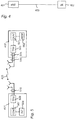
- Figure 4 is a simplified system architecture only showing some elements and functional entities, all being logical units whose implementation may differ from what is shown .
- the connections shown in Figure 4 are logical connections; the actual physical connections may be different. It is apparent to a person skilled in the art that the systems also comprise other functions and structures. It should be appreciated that the functions, structures, elements, and protocols used in or for wireless communication are irrelevant to the actual invention. Therefore, they need not be discussed in more detail here.
- the exemplary radio system of Figure 4 comprises a network apparatus 401 of a network operator.
- the network apparatus 401 may include e.g.
- a base station (node B, eNB) 401 access point (AP), radio network controller (RNC), MSC server (MSS), serving GPRS support node, mobility management entity (MME), home location register (HLR), home subscriber server (HSS), visitor location register (VLR) or any other network element or a combination of network elements.
- Figure 4 shows a user equipment 402 located in the service area of the base station 401.
- the base station 401 may be connected to the user equipment e.g. via a connection 403.
- the user equipment refers to a portable computing device, and it may also be referred to as a user terminal.
- Such computing devices include wireless mobile communication devices operating with or without a subscriber identification module (SIM), including, but not limited to, the following types of devices: mobile phone, smart-phone, personal digital assistant (PDA), handset, laptop computer.
- SIM subscriber identification module
- the base station 401 and the user equipment 402 are capable of connecting to each other via an access network via the connection 403.
- Figure 4 only illustrates a simplified example.
- the net-work may include more base stations and user terminals, and more cells may be formed by the base stations.
- the networks of two or more operators may overlap, the sizes and form of the cells may vary from what is depicted in Figure 4 , etc.
- the communication system may also be able to communicate with other networks, such as a public switched telephone net-work.
- FIG. 5 illustrates examples of apparatuses according to embodiments of the invention.
- Figure 5 shows a user equipment 402 located in the area of the base station or eNB 401.
- the user equipment is configured to be in connection with the base station 401.
- the user equipment or UE 402 comprises a controller 501 operationally connected to a memory 502 and a transceiver 503.
- the controller 501 controls the operation of the user equipment 402.
- the memory 502 is configured to store software and data.
- the transceiver 503 is configured to set up and maintain a wireless connection to the base station 401.
- the transceiver may be operationally connected to a set of antenna ports 504 connected to an antenna arrangement 505.
- the antenna arrangement 505 may comprise a set of antennas.
- the number of antennas may be one to four, for example.
- the number of antennas is not limited to any particular number.
- the user equipment 402 may also comprise various other components, such as a user interface, camera, and media player. They are not displayed in the figure due to simplicity.
- the base station or eNB 401 comprises a controller 507 operationally connected to an interface 508 and a transceiver 509. The controller 507 controls the operation of the base station 501.
- the interface 508 is configured to setup and maintain the connection with a further network element (not shown).
- the transceiver 509 is configured to set up and maintain a wireless connection to the user equipment 402 within the service area of the base station 401.
- the transceiver 509 may be operationally connected to an antenna arrangement 510.
- the antenna arrangement may comprise a set of antennas. The number of antennas may be two to four, for example. The number of antennas is not limited to any particular number.
- the base station may be operationally connected (directly or indirectly) to a further network element (not shown) of the communication system.
- the further network element may be a radio network controller MSC server (MSS), serving GPRS support node, mobility management entity (MME), home location register (HLR), home subscriber server (HSS), visitor location register (VLR), a radio network controller (RNC), a gateway, or a server, for example.
- MSC radio network controller
- MME mobility management entity
- HLR home location register
- HSS home subscriber server
- VLR visitor location register
- RNC radio network controller
- gateway a server, for example.
- the embodiments are not, however, restricted to the network given above as an example, but a person skilled in the art may apply the solution to other communication networks provided with the necessary properties.
- the connec tions between different network elements may be realized witch internet protocol (IP) connections.
- IP internet protocol
- the memory may include volatile and/or non-volatile memory and typically stores contend, data, or the like.
- the memory may store computer program code such as software applications (for example for the detector unit and/or for the adjuster unit) or operating systems, information, data, content, or the like for the processor to perform steps associated with operation of the apparatus in accordance with embodiments.
- the memory may be, for example, random access memory (RAM), a hard drive, or other fixed data memory or storage device. Further, the memory, or part of it, may be removable memory detachably connected to the apparatus.
- an apparatus implementing one or more functions, of a corresponding mobile entity described with an embodiment comprises not only prior art means, but also means for implementing the one or more functions of a corresponding apparatus described with an embodiment and it may comprise separate means for each separate function, or means may be configured to perform two or more functions.
- these techniques may be implemented in hardware (one or more apparatuses), firmware (one or more apparatuses), software (one or more modules), or combinations thereof.
- implementation can be through modules (e.g., procedures, functions, and so on) that perform the functions described herein.
- the software codes may be stored in any suitable, processor/computer-readable data storage medium(s) or memory unit(s) or article(s) of manufacture and executed by one or more processors/computers.
- the data storage medium or the memory unit may be implemented within the processor/computer or external to the processor/computer, in which case it can be communicatively coupled to the processor/computer via various means as is known in the art.
- User equipment may refer to any user communication device.
- a term "user equipment” as used herein may refer to any device having a communication capability, such as a wireless mobile terminal, a PDA, a smart phone, a personal computer (PC), a laptop computer, a desktop computer, etc.
- the wireless communication terminal may be an UMTS or GSM/EDGE smart mobile terminal.
- the application capabilities of the device may include native applications available in the terminal, or subsequently installed applications.
- the messaging service center may be implemented in any network element, such as a server.
- Figure 5 is a block diagram cf an apparatus according to an embodiment of the invention. Although the apparatus has been depicted as one entity, different modules and memory may be implemented in one or more physical or logical entities. The functionality of the network element 401 is described in more detail below with Figures 6 to 8 . It should be appreciated that the apparatus 401 may comprise other units used in or for access network selection. However, they are irrelevant to the actual invention and, therefore, they need not to be discussed in more detail here.
- the apparatus may also be a user terminal which is a piece of equipment or a device that associates, or is arranged to associate, the user terminal and its user with a subscription and allows a user to interact with a communications system.
- the user terminal presents information to the user and allows the user to input information.
- the user terminal may be any terminal capable of receiving information from and/or transmitting in-formation to the network, connectable to the network wirelessly or via a fixed connection. Examples of the user terminal include a personal computer, a game console, a laptop (a notebook), a personal digital assistant, a mobile station (mobile phone), and a line telephone.
- the apparatus 401 may generally include a processor, controller, control unit or the like connected to a memory and to various interfaces of the apparatus.
- the processor is a central processing unit, but the processor may be an additional operation processor.
- the processor may comprise a computer processor, application-specific integrated circuit (ASIC), field-programmable gate array (FPGA), and/or other hardware components that have been programmed in such a way to carry out one or more functions of an embodiment.
- ASIC application-specific integrated circuit
- FPGA field-programmable gate array
- the techniques described herein may be implemented by various means so that an apparatus implementing one or more functions of a corresponding mobile entity described with an embodiment comprises not only prior art means, but also means for implementing the one or more functions of a corresponding apparatus described with an embodiment and it may comprise separate means for each separate function, or means may be configured to perform two or more functions.
- these techniques may be implemented in hardware (one or more apparatuses), firmware (one or more apparatuses), software (one or more modules), or combinations thereof.
- implementation can be through modules (e.g., procedures, functions, and so on) that perform the functions described herein.
- the software codes may be stored in any suitable, processor/computer-readable data storage medium(s) or memory unit(s) or article(s) of manufacture and executed by one or more processors/computers.
- the data storage medium or the memory unit may be implemented within the processor/computer or external to the processor/computer, in which case it can be communicatively coupled to the processor/computer via various means as is known in the art.
- the signaling chart of Figure 6 illustrates the required signalling.
- a network apparatus 401 which may comprise e.g. a base station (eNB), defines, in 601, a muting pattern regarding uplink signals that are to be temporarily muted, such that the uplink signals comprise higher layer configured uplink signals that are outside the control of a dynamic scheduler of the network apparatus.
- the apparatus is configured to control one or more user terminals 402 to mute said uplink signals according to said muting pattern, by signalling 602 the defined muting pattern (or at least a part of the muting pattern) to the user equipment 402 (user terminal, UE).
- the user terminal 402 receives the muting pattern from the apparatus 401 and applies the muting pattern by muting higher layer configured uplink signals that are outside the control of a dynamic scheduler of the network apparatus, according to the muting pattern (cr the part of the muting pattern) received from the networks apparatus.
- the user equipment 402 is configured to transmit 604, to the apparatus 401, signalling where selected higher layer configured uplink signals have been muted by the user equipment 402 according to (the part of) the muting pattern received from the apparatus 401.
- the apparatus 401 is configured to receive, from the user equipment 402, signalling where selected higher layer configured uplink signals have been muted by the user equipment 402 according to the muting pattern transmitted by the apparatus 401.
- FIG. 7 is a flow chart illustrating an exemplary embodiment.
- the apparatus 401 which may comprise e.g. a base station (eNB), is configured to define, in 701, a muting pattern regarding uplink signals that are to be temporarily muted, the uplink signals comprising higher layer configured uplink signals that are outside the control of a dynamic scheduler of the network apparatus.
- eNB base station
- the apparatus is configured to control one or more user terminals 402 to mute uplink signals according to said pattern, by transmitting, in 702, the defined muting pattern or a part of the pattern to the user equipment 402.
- the apparatus 401 is configured to receive, from the user equipment 402, signalling where selected higher layer configured uplink signals have been muted by the user equipment 402 according to (the part of) the muting pattern transmitted by the apparatus 401.
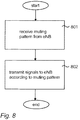
- Figure 8 is a flow chart illustrating an exemplary embodiment.
- the user terminal (user equipment UE) 402 is configured to receive, in 801, muting pattern (or a part of the muting pattern) regarding uplink signals that are to be temporarily muted, the uplink signals comprising higher layer configured uplink signals that are outside the control of a dynamic scheduler of a network apparatus 401.
- the user terminal 402 and applies (the part of) the muting pattern by muting higher layer configured uplink signals that are outside the control of a dynamic scheduler of the network apparatus, According to the muting pattern received from the network apparatus.
- the user equipment 402 is configured to transmit, in 902, to the apparatus 401, signalling where selected higher layer configured uplink signals have been muted by the user equipment 402 According to (the part of) the muting pattern received from the apparatus 401. It will be obvious to a person skilled in the art that, as the technology advances, the inventive concept may be implemented in various ways, within the scope of the appended claims.
Landscapes
- Engineering & Computer Science (AREA)
- Quality & Reliability (AREA)
- Computer Networks & Wireless Communication (AREA)
- Signal Processing (AREA)
- Mobile Radio Communication Systems (AREA)
Claims (17)
- Verfahren zum Steuern des Stummschaltens von Uplink-Signalen, die auf höherer Ebene konfiguriert sind, wobei das Verfahren Folgendes umfasst:Definieren, in einer Netzwerkeinrichtung, eines Stummschaltmusters (601) hinsichtlich der Uplink-Signale, die vorübergehend stumm geschaltet werden sollen, wobei diese Uplink-Signale auf höherer Ebene konfigurierte Uplink-Signale umfassen;Signalisieren mindestens eines Teils des definierten Stummschaltmusters von der Netzwerkeinrichtung an mindestens eine Benutzereinrichtung (602), um die mindestens eine Benutzereinrichtung so zu steuern, dass die Uplink-Signale gemäß dem signalisierten Muster stumm geschaltet werden; undAuslösen des Stummschaltens auf der Basis eines spezifischen stummschaltenden physikalischen Downlink-Steuerkanals, der eine zellenspezifische, benutzereinrichtungsspezifische oder benutzereinrichtungsgruppenspezifische Kennzeichnung aufweist.
- Netzwerkeinrichtung zum Steuern des Stummschaltens von Uplink-Signalen, die auf höherer Ebene konfiguriert sind, wobei die Einrichtung dazu ausgestaltet ist,
ein Stummschaltmuster (701) hinsichtlich der Uplink-Signale zu definieren, die vorübergehend stumm geschaltet werden sollen, wobei diese Uplink-Signale auf höherer Ebene konfigurierte Uplink-Signale umfassen;
mindestens einen Teil des definierten Stummschaltmusters an mindestens eine Benutzereinrichtung (702) zu signalisieren, um die mindestens eine Benutzereinrichtung so zu steuern, dass die Uplink-Signale gemäß dem signalisierten Muster stumm geschaltet werden; und
das Stummschalten auf der Basis eines spezifischen stummschaltenden physikalischen Downlink-Steuerkanals, der eine zellenspezifische, benutzereinrichtungsspezifische oder benutzereinrichtungsgruppenspezifische Kennzeichnung aufweist, auszulösen. - Einrichtung nach Anspruch 2, wobei das Stummschaltmuster benutzereinrichtungsspezifisch, zellenspezifisch oder netzwerkspezifisch ist.
- Einrichtung nach Anspruch 2 oder 3, wobei die Einrichtung dazu ausgestaltet ist, Informationen, die sich auf das Stummschaltmuster beziehen, an eine weitere Netzwerkeinrichtung zu transportieren.
- Einrichtung nach Anspruch 2, 3 oder 4, wobei die Einrichtung dazu ausgestaltet ist, das Stummschaltmuster für eine oder mehrere Zelle/n zu definieren, wobei die Einrichtung dazu ausgestaltet ist, das Stummschaltmuster unter mehreren Zellen in einem bestimmten geografischen Gebiet über standardisierte Signalisierung mit einer weiteren Einrichtung oder über eine nicht standardisierte Betriebs- und Instandhaltungsfunktion O&M (Operation and Maintenance) zu koordinieren.
- Einrichtung nach einem der Ansprüche 2 bis 5, wobei die Einrichtung dazu ausgestaltet ist, das Stummschaltmuster zu definieren, das für mehrere Zellen, die einer selben Netzwerkebene entsprechen, gemeinsam sein soll.
- Benutzereinrichtung zum Stummschalten von Uplink-Signalen, die auf höherer Ebene konfiguriert sind, wobei die Benutzereinrichtung dazu ausgestaltet ist,
von einer Netzwerkeinrichtung mindestens einen Teil eines Stummschaltmusters (801) hinsichtlich der Uplink-Signale, die vorübergehend stumm geschaltet werden sollen, zu empfangen, wobei diese Uplink-Signale auf höherer Ebene konfigurierte Uplink-Signale umfassen;
von einer Netzwerkeinrichtung einen spezifischen stummschaltenden physikalischen Downlink-Steuerkanal, der eine zellenspezifische, benutzereinrichtungsspezifische oder benutzereinrichtungsgruppenspezifische Kennzeichnung aufweist, zu empfangen; und
die auf höherer Ebene konfigurierten Uplink-Signale gemäß dem spezifischen stummschaltenden physikalischen Downlink-Steuerkanal und dem Muster stumm zu schalten, das von der Netzwerkeinrichtung (802) empfangen wird. - Benutzereinrichtung nach Anspruch 7, wobei die Benutzereinrichtung dazu ausgestaltet ist, diese Signale durch Fallenlassen der auf höherer Ebene konfigurierten Uplink-Übertragung gemäß dem empfangenen Muster stumm zu schalten.
- Benutzereinrichtung nach Anspruch 7 oder 8, wobei die Benutzereinrichtung dazu ausgestaltet ist, diese Signale durch Reduzieren der Übertragungsleistung für die auf höherer Ebene konfigurierte Uplink-Übertragung gemäß dem Stummschaltmuster und gemäß einem zuvor definierten Übertragungsleistungsversatz stumm zu schalten.
- Benutzereinrichtung nach Anspruch 7, 8 oder 9, wobei die Benutzereinrichtung dazu ausgestaltet ist, diese Signale in einer frequenzselektiven Weise dergestalt stumm zu schalten, dass das Stummschalten auf einen ausgewählten Uplink-Frequenzabschnitt einer Systembandbreite beschränkt ist, oder dergestalt, dass das Stummschalten einem Frequenzspreizmuster folgt.
- Benutzereinrichtung nach einem der Ansprüche 7 bis 10, wobei die Benutzereinrichtung dazu ausgestaltet ist, das Stummschaltmuster einschließlich der Dauer des Stummschaltens über Signalisierung auf höherer Ebene zu empfangen, wobei die Signalisierung auf höherer Ebene dedizierte Funkressourcensteuersignalisierung oder Rundsendungssignalisierung umfasst.
- Benutzereinrichtung nach einem der Ansprüche 7 bis 11, wobei die Benutzereinrichtung dazu ausgestaltet ist, das Stummschaltmuster durch Nutzlastbits eines stummschaltenden physikalischen Downlink-Steuerkanals zu empfangen.
- Benutzereinrichtung nach einem der Ansprüche 7 bis 12, wobei die Benutzereinrichtung dazu ausgestaltet ist, eine Vordefinition einer maximalen Verarbeitungszeit zu empfangen, nach welcher der Stummschaltbefehl gültig wird.
- Benutzereinrichtung nach einem der Ansprüche 7 bis 13, wobei die Benutzereinrichtung dazu ausgestaltet ist, das tatsächliche Stummschalten dergestalt auszuführen, dass eine festgelegte zeitliche Beziehung zwischen einem empfangenen stummschaltenden physikalischen Downlink-Steuerkanal und dem tatsächlichen Stummschalten besteht.
- Benutzereinrichtung nach einem der Ansprüche 7 bis 14, wobei die Benutzereinrichtung dazu ausgestaltet ist, mögliche Startpositionen für das Stummschalten über höhere Ebenen unter Verwendung dedizierter Funkressourcensteuerungssignalisierung oder Rundsendungssignalisierung zu empfangen.
- Kommunikationssystem, umfassend eine Einrichtung zum Steuern des Stummschaltens von Uplink-Signalen, die auf höherer Ebene konfiguriert sind, und mindestens eine Benutzereinrichtung, wobei das System dazu ausgestaltet ist,
in der Einrichtung ein Stummschaltmuster (601) hinsichtlich der Uplink-Signale zu definieren, die vorübergehend stumm geschaltet werden sollen, wobei diese Uplink-Signale auf höherer Ebene konfigurierte Uplink-Signale umfassen; und
mindestens einen Teil des definierten Stummschaltmusters von der Einrichtung an die mindestens eine Benutzereinrichtung (602) zu signalisieren, um die mindestens eine Benutzereinrichtung so zu steuern, dass die Uplink-Signale gemäß dem signalisierten Muster stumm geschaltet werden; und
das Stummschalten auf der Basis eines spezifischen stummschaltenden physikalischen Downlink-Steuerkanals auszulösen, der eine zellenspezifische, benutzereinrichtungsspezifische oder benutzereinrichtungsgruppenspezifische Kennzeichnung aufweist. - Computerlesbares Speichermedium, ein Programm mit Anweisungen verkörpernd, die durch einen Prozessor ausgeführt werden können, um Vorgänge durchzuführen, die sich auf das Stummschalten von auf höherer Ebene konfigurierter Uplink-Signale beziehen, wobei die Vorgänge Folgendes umfassen
Definieren, in einer Netzwerkeinrichtung, eines Stummschaltmusters (601) hinsichtlich der Uplink-Signale, die vorübergehend stumm geschaltet werden sollen, wobei diese Uplink-Signale auf höherer Ebene konfigurierte Uplink-Signale umfassen;
Signalisieren mindestens eines Teils des definierten Stummschaltmusters von der Netzwerkeinrichtung an mindestens eine Benutzereinrichtung (602), um die mindestens eine Benutzereinrichtung so zu steuern, dass diese Uplink-Signale gemäß dem signalisierten Muster stumm geschaltet werden; und
Auslösen des Stummschaltens auf der Basis eines spezifischen stummschaltenden physikalischen Downlink-Steuerkanals, der eine zellenspezifische, benutzereinrichtungsspezifische oder benutzereinrichtungsgruppenspezifische Kennzeichnung aufweist.
Applications Claiming Priority (1)
| Application Number | Priority Date | Filing Date | Title |
|---|---|---|---|
| PCT/EP2011/052060 WO2012107106A1 (en) | 2011-02-11 | 2011-02-11 | Signalling a muting pattern to a user equipment for time domain enhanced inter -cell interference coordination |
Publications (2)
| Publication Number | Publication Date |
|---|---|
| EP2674005A1 EP2674005A1 (de) | 2013-12-18 |
| EP2674005B1 true EP2674005B1 (de) | 2016-05-11 |
Family
ID=44515312
Family Applications (1)
| Application Number | Title | Priority Date | Filing Date |
|---|---|---|---|
| EP11704760.5A Active EP2674005B1 (de) | 2011-02-11 | 2011-02-11 | Signalisierung eines stummschaltmusters auf einem benutzergerät zur zeitbereichsverstärkten interferenzkoordination zwischen zellen |
Country Status (4)
| Country | Link |
|---|---|
| US (1) | US20130343315A1 (de) |
| EP (1) | EP2674005B1 (de) |
| CN (1) | CN103460776A (de) |
| WO (1) | WO2012107106A1 (de) |
Families Citing this family (17)
| Publication number | Priority date | Publication date | Assignee | Title |
|---|---|---|---|---|
| US20110230144A1 (en) | 2010-03-17 | 2011-09-22 | Iana Siomina | Method and Apparatus for Muting Signaling in a Wireless Communication Network |
| WO2013041757A1 (en) | 2011-09-23 | 2013-03-28 | Nokia Siemens Networks Oy | Spectrum sharing using sharing profiles |
| JP5858046B2 (ja) * | 2011-09-30 | 2016-02-10 | 富士通株式会社 | 無線通信システム、移動局、基地局及び無線通信システム制御方法 |
| GB2497743B (en) * | 2011-12-19 | 2017-09-27 | Sca Ipla Holdings Inc | Telecommunications systems and methods |
| US20150181437A1 (en) * | 2013-12-23 | 2015-06-25 | Broadcom Corporation | System and Method for Reception Adaption to Reduce Transmission Interference in a Device That Implements More Than One Wireless Technology |
| US9635566B2 (en) | 2014-04-25 | 2017-04-25 | At&T Intellectual Property I, L.P. | Enhancement of access points to support heterogeneous networks |
| US9516564B2 (en) | 2014-04-25 | 2016-12-06 | At&T Intellectual Property I, L.P. | Enhancement of a cell reselection parameter in heterogeneous networks |
| WO2016028216A2 (en) * | 2014-08-21 | 2016-02-25 | Telefonaktiebolaget L M Ericsson (Publ) | Enabling interference mitigation for over-the-air synchronization |
| US9621294B2 (en) | 2014-10-02 | 2017-04-11 | At&T Intellectual Property I, L.P. | Enhancement of inter-cell interference coordination with adaptive reduced-power almost blank subframes based on neighbor cell profile data |
| US9648582B2 (en) * | 2014-11-06 | 2017-05-09 | Intel IP Corporation | RAN paging mechanism to enable enhanced coverage mode |
| US9918344B2 (en) | 2015-04-09 | 2018-03-13 | Intel IP Corporation | Random access procedure for enhanced coverage support |
| CN109561433B (zh) * | 2016-08-10 | 2020-03-20 | 华为技术有限公司 | 数据信道发送和接收方法、网络设备及终端 |
| US11252730B2 (en) * | 2016-10-26 | 2022-02-15 | Lg Electronics Inc. | Method for performing beam management in wireless communication system and apparatus therefor |
| US10608755B2 (en) * | 2016-11-23 | 2020-03-31 | Aram Falsafi | Method and apparatus for wireless communication with improved performance |
| WO2018210260A1 (en) * | 2017-05-17 | 2018-11-22 | Mediatek Singapore Pte. Ltd. | Method and apparatus for handling cell-specific reference signal muting in mobile communications |
| US11792798B2 (en) * | 2020-02-26 | 2023-10-17 | Qualcomm Incorporated | System and method for silencing communication |
| US12550070B2 (en) * | 2023-10-03 | 2026-02-10 | Qualcomm Incorporated | Power reduction techniques for non-transparent uplink-muting |
Family Cites Families (9)
| Publication number | Priority date | Publication date | Assignee | Title |
|---|---|---|---|---|
| JP5416140B2 (ja) * | 2008-02-08 | 2014-02-12 | ゼットティーイー(ユーエスエー)インコーポレーテッド | Tdd無線システムにおけるダウンリンク/アップリンク割当比の動的調整 |
| US8483149B2 (en) * | 2008-12-05 | 2013-07-09 | Nokia Siemens Networks Oy | Resource allocation technique for physical uplink control channel blanking |
| WO2010105693A1 (en) * | 2009-03-20 | 2010-09-23 | Nokia Siemens Networks Oy | Reduced interference between local area cell and wide area cell |
| US8948105B2 (en) * | 2009-04-28 | 2015-02-03 | Zte (Usa) Inc. | Method and system for dynamic adjustment of downlink/uplink allocation ratio in LTE/TDD system |
| WO2011052965A2 (en) * | 2009-10-28 | 2011-05-05 | Lg Electronics Inc. | Dynamic uplink power control method and device in a wireless communications system |
| WO2011055986A2 (en) * | 2009-11-08 | 2011-05-12 | Lg Electronics Inc. | A method and a base station for transmitting a csi-rs, and a method and a user equipment for receiving the csi-rs |
| US8638868B2 (en) * | 2010-06-23 | 2014-01-28 | Telefonaktiebolaget L M Ericsson (Publ) | Methods and apparatus for varying reduced transmission resources |
| EP2604079A2 (de) * | 2010-08-11 | 2013-06-19 | Telefonaktiebolaget LM Ericsson (publ) | Verfahren zur zellengruppierung für positionierung und zugehörige netzwerke und vorrichtungen |
| WO2012023894A1 (en) * | 2010-08-20 | 2012-02-23 | Telefonaktibeolaget Lm Ericsson (Publ) | Method and node for reduced transmission activity pattern configuration |
-
2011
- 2011-02-11 EP EP11704760.5A patent/EP2674005B1/de active Active
- 2011-02-11 US US13/984,676 patent/US20130343315A1/en not_active Abandoned
- 2011-02-11 WO PCT/EP2011/052060 patent/WO2012107106A1/en not_active Ceased
- 2011-02-11 CN CN2011800699754A patent/CN103460776A/zh active Pending
Also Published As
| Publication number | Publication date |
|---|---|
| US20130343315A1 (en) | 2013-12-26 |
| WO2012107106A1 (en) | 2012-08-16 |
| CN103460776A (zh) | 2013-12-18 |
| EP2674005A1 (de) | 2013-12-18 |
Similar Documents
| Publication | Publication Date | Title |
|---|---|---|
| EP2674005B1 (de) | Signalisierung eines stummschaltmusters auf einem benutzergerät zur zeitbereichsverstärkten interferenzkoordination zwischen zellen | |
| CN115804136B (zh) | 交叉链路干扰测量配置 | |
| CN110582978B (zh) | 低等待时间系统中的探通参考信号配置和传输块大小缩放 | |
| EP2638719B1 (de) | Interferenzenmanagement für koexistierende radio systeme | |
| CN107409395B (zh) | 用于无线通信中的灵活双工的控制信令 | |
| CN115398972B (zh) | 无线通信移动性的参考测量定时选择 | |
| CN115380554B (zh) | 交叉链路干扰(cli)测量适配 | |
| EP3343970B1 (de) | Interferenzanzeigeverfahren und -vorrichtung | |
| KR20120080478A (ko) | 무선통신 시스템에서 기기내 공존 간섭을 조정하는 장치 및 방법 | |
| US12108429B2 (en) | Channel state information for full-duplex and half-duplex wireless communication | |
| CN114946208A (zh) | 用于l1/l2小区间移动性的用户设备(ue)能力和启用标志 | |
| US11743014B2 (en) | Reference signal receive power adaptation for sidelink traffic | |
| US20230262529A1 (en) | Wireless communication using multiple active bandwidth parts | |
| US12328773B2 (en) | Configurations for narrowband wireless communication | |
| US9232514B2 (en) | Apparatus and method for a communication system | |
| JP2025106252A (ja) | 非同期時分割複信のための干渉緩和方式 | |
| WO2017172100A1 (en) | Interference mitigation in cellular networks | |
| EP4144032B1 (de) | Kommunikation nach änderung des bandbreitenanteils | |
| CN117044316A (zh) | 用于双订阅双活动(dsda)操作的用户设备(ue)发射功率控制 | |
| US20120327867A1 (en) | Subframe Scheduling | |
| WO2024020276A1 (en) | Component carrier conflict management at a wireless communication device with multiple subscriptions | |
| US20250203430A1 (en) | Apparatus and method for measuring cross link interference and receiving downlink signal in a wireless network | |
| US12185330B2 (en) | Physical downlink control channel (PDCCH) reliability enhancement | |
| CN118696595A (zh) | 用于侧链路和蜂窝通信的非连续接收对准分组 | |
| US20220256564A1 (en) | Maintaining industrial internet of things (iiot) scheduling availability |
Legal Events
| Date | Code | Title | Description |
|---|---|---|---|
| PUAI | Public reference made under article 153(3) epc to a published international application that has entered the european phase |
Free format text: ORIGINAL CODE: 0009012 |
|
| 17P | Request for examination filed |
Effective date: 20130911 |
|
| AK | Designated contracting states |
Kind code of ref document: A1 Designated state(s): AL AT BE BG CH CY CZ DE DK EE ES FI FR GB GR HR HU IE IS IT LI LT LU LV MC MK MT NL NO PL PT RO RS SE SI SK SM TR |
|
| DAX | Request for extension of the european patent (deleted) | ||
| 17Q | First examination report despatched |
Effective date: 20140806 |
|
| REG | Reference to a national code |
Ref country code: DE Ref legal event code: R079 Ref document number: 602011026392 Country of ref document: DE Free format text: PREVIOUS MAIN CLASS: H04W0072080000 Ipc: H04W0072120000 |
|
| GRAP | Despatch of communication of intention to grant a patent |
Free format text: ORIGINAL CODE: EPIDOSNIGR1 |
|
| RIC1 | Information provided on ipc code assigned before grant |
Ipc: H04W 72/12 20090101AFI20151111BHEP |
|
| INTG | Intention to grant announced |
Effective date: 20151208 |
|
| GRAS | Grant fee paid |
Free format text: ORIGINAL CODE: EPIDOSNIGR3 |
|
| GRAA | (expected) grant |
Free format text: ORIGINAL CODE: 0009210 |
|
| AK | Designated contracting states |
Kind code of ref document: B1 Designated state(s): AL AT BE BG CH CY CZ DE DK EE ES FI FR GB GR HR HU IE IS IT LI LT LU LV MC MK MT NL NO PL PT RO RS SE SI SK SM TR |
|
| REG | Reference to a national code |
Ref country code: GB Ref legal event code: FG4D |
|
| REG | Reference to a national code |
Ref country code: CH Ref legal event code: EP |
|
| REG | Reference to a national code |
Ref country code: AT Ref legal event code: REF Ref document number: 799516 Country of ref document: AT Kind code of ref document: T Effective date: 20160515 |
|
| REG | Reference to a national code |
Ref country code: IE Ref legal event code: FG4D |
|
| REG | Reference to a national code |
Ref country code: DE Ref legal event code: R096 Ref document number: 602011026392 Country of ref document: DE |
|
| REG | Reference to a national code |
Ref country code: LT Ref legal event code: MG4D |
|
| REG | Reference to a national code |
Ref country code: NL Ref legal event code: MP Effective date: 20160511 |
|
| PG25 | Lapsed in a contracting state [announced via postgrant information from national office to epo] |
Ref country code: FI Free format text: LAPSE BECAUSE OF FAILURE TO SUBMIT A TRANSLATION OF THE DESCRIPTION OR TO PAY THE FEE WITHIN THE PRESCRIBED TIME-LIMIT Effective date: 20160511 Ref country code: LT Free format text: LAPSE BECAUSE OF FAILURE TO SUBMIT A TRANSLATION OF THE DESCRIPTION OR TO PAY THE FEE WITHIN THE PRESCRIBED TIME-LIMIT Effective date: 20160511 Ref country code: NO Free format text: LAPSE BECAUSE OF FAILURE TO SUBMIT A TRANSLATION OF THE DESCRIPTION OR TO PAY THE FEE WITHIN THE PRESCRIBED TIME-LIMIT Effective date: 20160811 Ref country code: NL Free format text: LAPSE BECAUSE OF FAILURE TO SUBMIT A TRANSLATION OF THE DESCRIPTION OR TO PAY THE FEE WITHIN THE PRESCRIBED TIME-LIMIT Effective date: 20160511 |
|
| REG | Reference to a national code |
Ref country code: AT Ref legal event code: MK05 Ref document number: 799516 Country of ref document: AT Kind code of ref document: T Effective date: 20160511 |
|
| PG25 | Lapsed in a contracting state [announced via postgrant information from national office to epo] |
Ref country code: HR Free format text: LAPSE BECAUSE OF FAILURE TO SUBMIT A TRANSLATION OF THE DESCRIPTION OR TO PAY THE FEE WITHIN THE PRESCRIBED TIME-LIMIT Effective date: 20160511 Ref country code: ES Free format text: LAPSE BECAUSE OF FAILURE TO SUBMIT A TRANSLATION OF THE DESCRIPTION OR TO PAY THE FEE WITHIN THE PRESCRIBED TIME-LIMIT Effective date: 20160511 Ref country code: PT Free format text: LAPSE BECAUSE OF FAILURE TO SUBMIT A TRANSLATION OF THE DESCRIPTION OR TO PAY THE FEE WITHIN THE PRESCRIBED TIME-LIMIT Effective date: 20160912 Ref country code: SE Free format text: LAPSE BECAUSE OF FAILURE TO SUBMIT A TRANSLATION OF THE DESCRIPTION OR TO PAY THE FEE WITHIN THE PRESCRIBED TIME-LIMIT Effective date: 20160511 Ref country code: LV Free format text: LAPSE BECAUSE OF FAILURE TO SUBMIT A TRANSLATION OF THE DESCRIPTION OR TO PAY THE FEE WITHIN THE PRESCRIBED TIME-LIMIT Effective date: 20160511 Ref country code: GR Free format text: LAPSE BECAUSE OF FAILURE TO SUBMIT A TRANSLATION OF THE DESCRIPTION OR TO PAY THE FEE WITHIN THE PRESCRIBED TIME-LIMIT Effective date: 20160812 Ref country code: RS Free format text: LAPSE BECAUSE OF FAILURE TO SUBMIT A TRANSLATION OF THE DESCRIPTION OR TO PAY THE FEE WITHIN THE PRESCRIBED TIME-LIMIT Effective date: 20160511 |
|
| PG25 | Lapsed in a contracting state [announced via postgrant information from national office to epo] |
Ref country code: IT Free format text: LAPSE BECAUSE OF FAILURE TO SUBMIT A TRANSLATION OF THE DESCRIPTION OR TO PAY THE FEE WITHIN THE PRESCRIBED TIME-LIMIT Effective date: 20160511 |
|
| PG25 | Lapsed in a contracting state [announced via postgrant information from national office to epo] |
Ref country code: CZ Free format text: LAPSE BECAUSE OF FAILURE TO SUBMIT A TRANSLATION OF THE DESCRIPTION OR TO PAY THE FEE WITHIN THE PRESCRIBED TIME-LIMIT Effective date: 20160511 Ref country code: SK Free format text: LAPSE BECAUSE OF FAILURE TO SUBMIT A TRANSLATION OF THE DESCRIPTION OR TO PAY THE FEE WITHIN THE PRESCRIBED TIME-LIMIT Effective date: 20160511 Ref country code: RO Free format text: LAPSE BECAUSE OF FAILURE TO SUBMIT A TRANSLATION OF THE DESCRIPTION OR TO PAY THE FEE WITHIN THE PRESCRIBED TIME-LIMIT Effective date: 20160511 Ref country code: DK Free format text: LAPSE BECAUSE OF FAILURE TO SUBMIT A TRANSLATION OF THE DESCRIPTION OR TO PAY THE FEE WITHIN THE PRESCRIBED TIME-LIMIT Effective date: 20160511 Ref country code: EE Free format text: LAPSE BECAUSE OF FAILURE TO SUBMIT A TRANSLATION OF THE DESCRIPTION OR TO PAY THE FEE WITHIN THE PRESCRIBED TIME-LIMIT Effective date: 20160511 |
|
| REG | Reference to a national code |
Ref country code: DE Ref legal event code: R097 Ref document number: 602011026392 Country of ref document: DE |
|
| PG25 | Lapsed in a contracting state [announced via postgrant information from national office to epo] |
Ref country code: SM Free format text: LAPSE BECAUSE OF FAILURE TO SUBMIT A TRANSLATION OF THE DESCRIPTION OR TO PAY THE FEE WITHIN THE PRESCRIBED TIME-LIMIT Effective date: 20160511 Ref country code: BE Free format text: LAPSE BECAUSE OF FAILURE TO SUBMIT A TRANSLATION OF THE DESCRIPTION OR TO PAY THE FEE WITHIN THE PRESCRIBED TIME-LIMIT Effective date: 20160511 Ref country code: AT Free format text: LAPSE BECAUSE OF FAILURE TO SUBMIT A TRANSLATION OF THE DESCRIPTION OR TO PAY THE FEE WITHIN THE PRESCRIBED TIME-LIMIT Effective date: 20160511 Ref country code: PL Free format text: LAPSE BECAUSE OF FAILURE TO SUBMIT A TRANSLATION OF THE DESCRIPTION OR TO PAY THE FEE WITHIN THE PRESCRIBED TIME-LIMIT Effective date: 20160511 |
|
| PLBE | No opposition filed within time limit |
Free format text: ORIGINAL CODE: 0009261 |
|
| STAA | Information on the status of an ep patent application or granted ep patent |
Free format text: STATUS: NO OPPOSITION FILED WITHIN TIME LIMIT |
|
| 26N | No opposition filed |
Effective date: 20170214 |
|
| PG25 | Lapsed in a contracting state [announced via postgrant information from national office to epo] |
Ref country code: SI Free format text: LAPSE BECAUSE OF FAILURE TO SUBMIT A TRANSLATION OF THE DESCRIPTION OR TO PAY THE FEE WITHIN THE PRESCRIBED TIME-LIMIT Effective date: 20160511 |
|
| PG25 | Lapsed in a contracting state [announced via postgrant information from national office to epo] |
Ref country code: MC Free format text: LAPSE BECAUSE OF FAILURE TO SUBMIT A TRANSLATION OF THE DESCRIPTION OR TO PAY THE FEE WITHIN THE PRESCRIBED TIME-LIMIT Effective date: 20160511 |
|
| REG | Reference to a national code |
Ref country code: CH Ref legal event code: PL |
|
| PG25 | Lapsed in a contracting state [announced via postgrant information from national office to epo] |
Ref country code: CH Free format text: LAPSE BECAUSE OF NON-PAYMENT OF DUE FEES Effective date: 20170228 Ref country code: LI Free format text: LAPSE BECAUSE OF NON-PAYMENT OF DUE FEES Effective date: 20170228 |
|
| REG | Reference to a national code |
Ref country code: IE Ref legal event code: MM4A |
|
| REG | Reference to a national code |
Ref country code: FR Ref legal event code: ST Effective date: 20171031 |
|
| PG25 | Lapsed in a contracting state [announced via postgrant information from national office to epo] |
Ref country code: LU Free format text: LAPSE BECAUSE OF NON-PAYMENT OF DUE FEES Effective date: 20170211 |
|
| PG25 | Lapsed in a contracting state [announced via postgrant information from national office to epo] |
Ref country code: FR Free format text: LAPSE BECAUSE OF NON-PAYMENT OF DUE FEES Effective date: 20170228 |
|
| PG25 | Lapsed in a contracting state [announced via postgrant information from national office to epo] |
Ref country code: IE Free format text: LAPSE BECAUSE OF NON-PAYMENT OF DUE FEES Effective date: 20170211 |
|
| PG25 | Lapsed in a contracting state [announced via postgrant information from national office to epo] |
Ref country code: MT Free format text: LAPSE BECAUSE OF NON-PAYMENT OF DUE FEES Effective date: 20170211 |
|
| PG25 | Lapsed in a contracting state [announced via postgrant information from national office to epo] |
Ref country code: AL Free format text: LAPSE BECAUSE OF FAILURE TO SUBMIT A TRANSLATION OF THE DESCRIPTION OR TO PAY THE FEE WITHIN THE PRESCRIBED TIME-LIMIT Effective date: 20160511 |
|
| PG25 | Lapsed in a contracting state [announced via postgrant information from national office to epo] |
Ref country code: HU Free format text: LAPSE BECAUSE OF FAILURE TO SUBMIT A TRANSLATION OF THE DESCRIPTION OR TO PAY THE FEE WITHIN THE PRESCRIBED TIME-LIMIT; INVALID AB INITIO Effective date: 20110211 |
|
| PG25 | Lapsed in a contracting state [announced via postgrant information from national office to epo] |
Ref country code: BG Free format text: LAPSE BECAUSE OF FAILURE TO SUBMIT A TRANSLATION OF THE DESCRIPTION OR TO PAY THE FEE WITHIN THE PRESCRIBED TIME-LIMIT Effective date: 20160511 |
|
| PG25 | Lapsed in a contracting state [announced via postgrant information from national office to epo] |
Ref country code: CY Free format text: LAPSE BECAUSE OF NON-PAYMENT OF DUE FEES Effective date: 20160511 |
|
| PG25 | Lapsed in a contracting state [announced via postgrant information from national office to epo] |
Ref country code: MK Free format text: LAPSE BECAUSE OF FAILURE TO SUBMIT A TRANSLATION OF THE DESCRIPTION OR TO PAY THE FEE WITHIN THE PRESCRIBED TIME-LIMIT Effective date: 20160511 |
|
| PG25 | Lapsed in a contracting state [announced via postgrant information from national office to epo] |
Ref country code: TR Free format text: LAPSE BECAUSE OF FAILURE TO SUBMIT A TRANSLATION OF THE DESCRIPTION OR TO PAY THE FEE WITHIN THE PRESCRIBED TIME-LIMIT Effective date: 20160511 |
|
| REG | Reference to a national code |
Ref country code: DE Ref legal event code: R081 Ref document number: 602011026392 Country of ref document: DE Owner name: WSOU INVESTMENTS, LLC, LOS ANGELES, US Free format text: FORMER OWNER: NOKIA SOLUTIONS AND NETWORKS OY, ESPOO, FI |
|
| PG25 | Lapsed in a contracting state [announced via postgrant information from national office to epo] |
Ref country code: IS Free format text: LAPSE BECAUSE OF FAILURE TO SUBMIT A TRANSLATION OF THE DESCRIPTION OR TO PAY THE FEE WITHIN THE PRESCRIBED TIME-LIMIT Effective date: 20160911 |
|
| REG | Reference to a national code |
Ref country code: DE Ref legal event code: R082 Ref document number: 602011026392 Country of ref document: DE Representative=s name: METACOM LEGAL RECHTSANWAELTE, DE Ref country code: DE Ref legal event code: R082 Ref document number: 602011026392 Country of ref document: DE Representative=s name: METACOM LEGAL, DE Ref country code: DE Ref legal event code: R082 Ref document number: 602011026392 Country of ref document: DE Representative=s name: METACOM LEGAL NAGEL MARKOWSKY VOSSIUS RECHTSAN, DE |
|
| P01 | Opt-out of the competence of the unified patent court (upc) registered |
Effective date: 20230606 |
|
| PGFP | Annual fee paid to national office [announced via postgrant information from national office to epo] |
Ref country code: DE Payment date: 20250729 Year of fee payment: 15 |
|
| PGFP | Annual fee paid to national office [announced via postgrant information from national office to epo] |
Ref country code: GB Payment date: 20250728 Year of fee payment: 15 |