EP2673759B1 - Method for making a parking arrangement equipped with an automatic vehicle detection system ready for operation, and parking arrangement for use of the method - Google Patents
Method for making a parking arrangement equipped with an automatic vehicle detection system ready for operation, and parking arrangement for use of the method Download PDFInfo
- Publication number
- EP2673759B1 EP2673759B1 EP12705487.2A EP12705487A EP2673759B1 EP 2673759 B1 EP2673759 B1 EP 2673759B1 EP 12705487 A EP12705487 A EP 12705487A EP 2673759 B1 EP2673759 B1 EP 2673759B1
- Authority
- EP
- European Patent Office
- Prior art keywords
- parking
- sensor modules
- parking sensor
- central computer
- places
- Prior art date
- Legal status (The legal status is an assumption and is not a legal conclusion. Google has not performed a legal analysis and makes no representation as to the accuracy of the status listed.)
- Active
Links
- 238000000034 method Methods 0.000 title claims description 35
- 238000001514 detection method Methods 0.000 title claims description 8
- 230000005540 biological transmission Effects 0.000 claims description 9
- 230000008878 coupling Effects 0.000 claims description 4
- 238000010168 coupling process Methods 0.000 claims description 4
- 238000005859 coupling reaction Methods 0.000 claims description 4
- 230000006870 function Effects 0.000 claims description 2
- 238000004891 communication Methods 0.000 description 7
- 230000008569 process Effects 0.000 description 6
- 230000000694 effects Effects 0.000 description 2
- 238000012986 modification Methods 0.000 description 2
- 230000004048 modification Effects 0.000 description 2
- 230000003213 activating effect Effects 0.000 description 1
- 230000002411 adverse Effects 0.000 description 1
- 230000033228 biological regulation Effects 0.000 description 1
- 230000008859 change Effects 0.000 description 1
- 238000012937 correction Methods 0.000 description 1
- 238000010586 diagram Methods 0.000 description 1
- 238000004519 manufacturing process Methods 0.000 description 1
- 238000005259 measurement Methods 0.000 description 1
Images



Classifications
-
- G—PHYSICS
- G08—SIGNALLING
- G08G—TRAFFIC CONTROL SYSTEMS
- G08G1/00—Traffic control systems for road vehicles
- G08G1/14—Traffic control systems for road vehicles indicating individual free spaces in parking areas
- G08G1/141—Traffic control systems for road vehicles indicating individual free spaces in parking areas with means giving the indication of available parking spaces
-
- G—PHYSICS
- G08—SIGNALLING
- G08G—TRAFFIC CONTROL SYSTEMS
- G08G1/00—Traffic control systems for road vehicles
- G08G1/01—Detecting movement of traffic to be counted or controlled
- G08G1/017—Detecting movement of traffic to be counted or controlled identifying vehicles
-
- G—PHYSICS
- G08—SIGNALLING
- G08G—TRAFFIC CONTROL SYSTEMS
- G08G1/00—Traffic control systems for road vehicles
- G08G1/14—Traffic control systems for road vehicles indicating individual free spaces in parking areas
-
- G—PHYSICS
- G08—SIGNALLING
- G08G—TRAFFIC CONTROL SYSTEMS
- G08G1/00—Traffic control systems for road vehicles
- G08G1/14—Traffic control systems for road vehicles indicating individual free spaces in parking areas
- G08G1/141—Traffic control systems for road vehicles indicating individual free spaces in parking areas with means giving the indication of available parking spaces
- G08G1/142—Traffic control systems for road vehicles indicating individual free spaces in parking areas with means giving the indication of available parking spaces external to the vehicles
-
- G—PHYSICS
- G08—SIGNALLING
- G08G—TRAFFIC CONTROL SYSTEMS
- G08G1/00—Traffic control systems for road vehicles
- G08G1/14—Traffic control systems for road vehicles indicating individual free spaces in parking areas
- G08G1/141—Traffic control systems for road vehicles indicating individual free spaces in parking areas with means giving the indication of available parking spaces
- G08G1/144—Traffic control systems for road vehicles indicating individual free spaces in parking areas with means giving the indication of available parking spaces on portable or mobile units, e.g. personal digital assistant [PDA]
-
- G—PHYSICS
- G08—SIGNALLING
- G08G—TRAFFIC CONTROL SYSTEMS
- G08G1/00—Traffic control systems for road vehicles
- G08G1/14—Traffic control systems for road vehicles indicating individual free spaces in parking areas
- G08G1/145—Traffic control systems for road vehicles indicating individual free spaces in parking areas where the indication depends on the parking areas
- G08G1/146—Traffic control systems for road vehicles indicating individual free spaces in parking areas where the indication depends on the parking areas where the parking area is a limited parking space, e.g. parking garage, restricted space
Definitions
- the invention relates to a method for making a parking arrangement equipped with an automatic vehicle detection system ready for operation, which parking arrangement comprises a central computer with a database and at least a number of parking places identifiable by a location code, which parking places are each provided with at least one wirelessly operating parking sensor module which is connected with the central computer via a UHF radio link, and which is provided with an identification code, which parking sensor module comprises at least one vehicle sensor which in operation provides measuring values which are representative of the presence or absence of a vehicle in the respective parking place.
- parking place is understood to mean a parking spot or a parking bay or parking space for a single vehicle.
- Parking arrangement is understood to mean an array of a number of parking places, such as, for instance, a parking lot, a parking garage, a parking zone, a parking lane or the like.
- Vehicle is understood to mean any type of vehicle that can be placed in a parking place, such as, for instance, a passenger car, a van, a camper, an autobus, trailer, etc.
- an automated parking guidance and management system in which parking sensor modules are used that can indicate the status of a parking place (occupied, vacant, occupied but not paid for, etc.) by means of light signals.
- These parking sensor modules are connected via cable work with connecting modules, which in turn are connected with a central computer via cable work and/or wirelessly.
- These known parking sensor modules are furthermore provided with an RFID reader, which can read out an RFID tag carried along in or on a car. This reference, however, does not disclose nor suggest a method for bringing a parking arrangement of the above-described type in a condition ready for operation, prior to opening to vehicles to be parked.
- an automated parking director system for directing parking in a parking lot having a plurality of parking spaces.
- Each parking space has a vehicle detector for detecting the presence of a vehicle in said parking space.
- the vehicle detectors have an RFID reader for reading out an RFID tag attached to a vehicle.
- a method for making ready for operation a parking arrangement has not been disclosed in US2004/0252034A1 .
- an identification code provided on a sensor node is read and noted down by an operator. Thereafter, on a floor plan of the parking arrangement a code designation, such as, for example, a number or the coordinates of the respective parking place, is looked up and noted down next to the just-noted identification number of the sensor node, or the other way around. This is done for all parking places of the parking arrangement and the thus obtained information is manually inputted into the database of the central computer. This is sometimes designated as locating process.
- a method of the above-described type is characterized in that use is made of parking sensor modules which have an RFID identification circuit, in which the identification code is stored, which identification code is wirelessly readable.
- a parking arrangement according to the invention is characterized in that at least a number of parking places of the parking arrangement are each provided with at least one parking sensor module, which parking sensor module is provided with an RFID identification circuit, in which a wirelessly readable identification code is stored.
- the parking sensor modules do not contain an RFID identification circuit.
- FIG. 1 shows schematically an example of a vehicle detection system 1 for a parking arrangement according to the invention.
- the vehicle detection system shown comprises a number of parking sensor modules, also named sensor nodes, indicated with P1, P2, ...Pn, Pn+1, ... Pm.
- the sensor nodes correspond to the different parking places of the parking arrangement.
- the sensor nodes are typically, but not necessarily, divided into a number of groups, whereby the sensor nodes of a group can communicate with an intermediate station, which in turn can communicate with the central computer of the vehicle detection system.
- the sensor nodes P1 ... Pn form a first group 2 and the sensor nodes Pn+1 ... Pm form a second group 3.
- Group 2 can communicate with an associated intermediate station 4 via a connection 5, while group 3 can communicate with an intermediate station 6 via a connection 7.
- the intermediate stations 4 and 6 can communicate with the central computer 10 via connections 8, 9.
- the connections 5, 7, 8, and 9 could, if desired, consist wholly or partly of wired connections, but are preferably wireless connections.
- a condition change occurs, as a result of a vehicle arriving or leaving, this is detected by the sensor node associated with that parking place and passed on via the associated intermediate station to the central computer.
- a parking arrangement can also be so configured that the sensor nodes communicate directly, or via other sensor nodes, with the central computer without intervention of intermediate stations such as the intermediate stations 4 and 6.
- the starting point is an automatic vehicle detection system with a single sensor node per parking place.
- more or fewer than two groups of sensor nodes may be used depending on the nature of the parking arrangement.
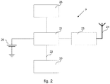
- FIG. 2 shows schematically the structure of an example of a parking sensor module P for use in a method or arrangement according to the invention.
- the parking sensor module (sensor node) P comprises a vehicle sensor 20, which can comprise, for example, one or more magnetic sensors, such as described, for example, in applicant's Dutch patent 2001994 .
- the vehicle sensor 20 is connected with a microcontroller 21, which receives signals generated by the vehicle sensor via a connection 22, processes them and transmits them to the central computer via a radio link with a transmitter/receiver 23 and an antenna 24. Communication between the sensor nodes mutually may also take place via this radio link.
- the radio link is usually a UHF link.
- the sensor node in this example furthermore comprises a low-frequency (LF) transmitter/receiver 25 with an LF antenna not shown separately.
- the transmitter/receiver 25 forms an RFID (Radio Frequency Identification Device) transponder, whose function will be further elucidated hereinbelow.
- the sensor node is provided with a battery 26 for providing supply voltage to the different circuits of the sensor node.
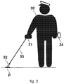
- FIG. 3 illustrates schematically a method according to the invention.
- the figure shows an operator 30 having in one hand a portable or mobile RFID reader 31, whose antenna 32 arranged on an extension stick 33 is held close to a sensor node P.
- the reader 31, if desired, may also be mounted lower on the stick 33 or may even, in a single housing together with the antenna, be attached to the distal end of the stick. However, the reader may also be connected to the antenna with a wire, via the stick or not so, and be worn elsewhere on the body of the operator, for example, suspended from his belt or on his back.
- the RFID transponder 25 in which the identification code, typically consisting of just a number, of the sensor node P is electronically stored, can be read out.
- the reader 31 is coupled, for instance via Bluetooth, with a so-called smartphone 34, carried along by the operator, and the read-out identification code of the sensor node P is automatically stored in the memory of the smartphone.
- the operator now only needs to input the location code, such as, for example, the number or the coordinates of the parking place, into the memory of the smartphone manually and forward it to the central computer 10 at a suitable time.
- the chance of errors is reduced considerably. If the parking places are consecutively numbered, the chance of errors can be further reduced by an automatic or semiautomatic increase or decrease of the parking place number in the smart phone application. Automatic increase or decrease may be done by coupling this to the input of a next identification code of a sensor node. For semiautomatic increase/decrease, for example, a button on the smartphone programmed for that purpose may be utilized.
- the locating process may be further supported by utilizing a positioning system.
- the GPS function of the smartphone may be utilized to input the coordinates of the parking place associated with a sensor node into the memory of the smartphone and to couple it to a sensor node identification code which has been read or is to be read with the reader 31.
- the RFID transponder 25 of the sensor nodes can also be used for logistics during the production of the sensor nodes.
- UHF radio link For normal operation, i.e., relaying parking information, communication between the sensor nodes mutually and from the nodes to the central computer takes place via a UHF radio link, as indicated in Figure 1 at 5 , 7, 8, and 9 and in Figure 2 at 23, 24.
- UHF signals are less suitable. Due to the large range of UHF signals and the small distance between adjacent sensor nodes, it is not always certain that with a reader suitable for UHF signals the correct identification code of a sensor node is registered if the automatic identification of the sensor nodes were carried out via the UHF link 23, 24.
- a solution to this problem is to utilize a low-frequency RFID method, as has already been described hereinabove.
- the low-frequency transmitter/receiver 25 may be utilized, in a similar manner to that described in applicant's older Dutch patent application NL2005776 , understood to be incorporated herein by reference, to determine the distance of each sensor node to neighboring sensor nodes.
- the sensor nodes are normally all situated substantially in the same horizontal plane.
- the sensor nodes are located close to each other, typically at a mutual distance in the order of 2.5 to 3 meters, in the use of magnetic fields low frequencies are employed in the so-called near field. In this near field it holds that the relation between field strength and distance r to the transmitter is inversely proportional to the third power of the distance r.
- the field strength at a distance r from an LF transmitter is proportional to 1 /r 3 and is a measure of the distance between the transmitter and the receiver.
- transponder circuit 25 or at least its antenna coil, of one of the sensor nodes as LF transmitter and using the transponder circuits of the other sensor nodes as LF receiver, it is possible, with the thus determined distances between the different nodes and utilizing algorithms known per se, to make by software a kind of ground plan of the relative location of the sensor nodes with respect to each other.
- existing techniques can be utilized for successively activating one of the sensor nodes as LF transmitter while the other sensor nodes operate as LF receiver.
- a suitable technique is the so-called TDMA (Time Division Multiple Access) method.
- This technique can be used for the UHF communication of the nodes, and the means then present for this purpose anyway can also be used to determine, under the control of the central computer and/or the microcontrollers 21, by means of LF communication between the nodes, the relative location of the nodes with respect to each other.
- the transmission frequency can be in the range of about 30 kHz to about 70 kHz, for instance, around 50 kHz.
- the map of the relative location of the sensor nodes with respect to each other can, together with the plan of the physical parking arrangement itself, be represented on the display of the central computer 10.
- Figure 4 shows schematically an example of a ground plan of a parking arrangement 40 with the parking places 41 and an entrance 42 and an exit 43 indicated thereon. Further, Figure 4 shows the map 44 of the relative location of the sensor nodes with respect to each other.
- the ground plan may be drawn in a usual manner and be inputted in the computer, but optionally the maps of Google Maps may be utilized for this purpose.
- the coordinates of the parking places can be simply obtained therefrom.
- the map 44 of the sensor nodes can be laid on the map 41 of the parking places so as to match it in a simple manner by shifting and/or turning and/or enlarging or reducing.
- the identification codes of the sensor nodes are unequivocally coupled to the physical parking places.
- Figure 5 shows how the map 44 of the sensor nodes has been laid on the map of the parking places on the display 45 of a monitor 46 of the central computer 10 with an unequivocal match.
- the determination of the distance between a sensor node and the other sensor nodes situated in the surroundings of that sensor node with the aid of low-frequency magnetic fields provides a very reliable result.
- the low-frequency signals unlike UHF signals, are not influenced, or influenced to a very minor extent only, by the surroundings.
- UHF communication link between the sensor nodes and the central computer can be used to automatically make, with the aid of suitable software, a map of the relative location of the sensor nodes with respect to each other.
- additional intermediate stations can be used, such as indicated, for example, at 4 and 6 in Figure 1 .
- these intermediate stations are preferably mounted high, for example, in a lamppost or a special pole or to the wall of a building or the like.
- the difference in transmission time of UHF signals from sensor nodes to the intermediate stations can be determined. Based on the difference in transmission time, the positions of the sensor nodes with respect to the intermediate stations can be calculated. Utilizing modern techniques for phase measurements, known per se, the different transmission times can be simply calculated.
- sensor nodes and/or intermediate stations with a GPS receiver or a comparable receiver, so that the geographical position of these sensor nodes and/or intermediate stations is already fixed and the coupling between the parking places and the sensor nodes can take place automatically.
- the reader 31 and the smartphone may then be used for checking and correction purposes only.
- the just-described UHF method is less accurate than the earlier-described LF method, though expectably this will not be a drawback at least in a number of situations, depending on nature and location of the parking arrangement.
- the reader 31 with the associated antenna may be carried along by the operator in various manners.
- a kind of small cart with wheels can be used, to which the antenna is attached.
- Such a cart could also be provided with propelling means and with a seat for the operator.
Landscapes
- Physics & Mathematics (AREA)
- General Physics & Mathematics (AREA)
- Traffic Control Systems (AREA)
Description
- The invention relates to a method for making a parking arrangement equipped with an automatic vehicle detection system ready for operation, which parking arrangement comprises a central computer with a database and at least a number of parking places identifiable by a location code, which parking places are each provided with at least one wirelessly operating parking sensor module which is connected with the central computer via a UHF radio link, and which is provided with an identification code, which parking sensor module comprises at least one vehicle sensor which in operation provides measuring values which are representative of the presence or absence of a vehicle in the respective parking place.
- In the following description, "parking place" is understood to mean a parking spot or a parking bay or parking space for a single vehicle. "Parking arrangement" is understood to mean an array of a number of parking places, such as, for instance, a parking lot, a parking garage, a parking zone, a parking lane or the like. "Vehicle" is understood to mean any type of vehicle that can be placed in a parking place, such as, for instance, a passenger car, a van, a camper, an autobus, trailer, etc.
- An example of a parking arrangement in which the present invention can be used is described in Dutch patent
2001994 2001994 - Further, from
WO 2009/117755 A2 an automated parking guidance and management system is known, in which parking sensor modules are used that can indicate the status of a parking place (occupied, vacant, occupied but not paid for, etc.) by means of light signals. These parking sensor modules are connected via cable work with connecting modules, which in turn are connected with a central computer via cable work and/or wirelessly. These known parking sensor modules are furthermore provided with an RFID reader, which can read out an RFID tag carried along in or on a car. This reference, however, does not disclose nor suggest a method for bringing a parking arrangement of the above-described type in a condition ready for operation, prior to opening to vehicles to be parked. - From
US2004/0252034A1 an automated parking director system is known for directing parking in a parking lot having a plurality of parking spaces. Each parking space has a vehicle detector for detecting the presence of a vehicle in said parking space. In one embodiment the vehicle detectors have an RFID reader for reading out an RFID tag attached to a vehicle. A method for making ready for operation a parking arrangement has not been disclosed inUS2004/0252034A1 . - According to a customary practice, an identification code provided on a sensor node, typically a number, is read and noted down by an operator. Thereafter, on a floor plan of the parking arrangement a code designation, such as, for example, a number or the coordinates of the respective parking place, is looked up and noted down next to the just-noted identification number of the sensor node, or the other way around. This is done for all parking places of the parking arrangement and the thus obtained information is manually inputted into the database of the central computer. This is sometimes designated as locating process.
- This is a laborious process, which can easily entail errors. The number of the sensor node, for example, may be poorly legible and hence, or for another reason, be misread, or be noted down incorrectly or be noted down in association with the wrong parking place. When the layout of the parking arrangement is changed, which occurs regularly, especially in the case of open-air lots, the same process needs to be traversed again, and once again errors may occur
- The object of the invention is to improve this process and to reduce the chance of errors. The invention is defined by the appended claims. To this end, according to the invention, a method of the above-described type is characterized in that use is made of parking sensor modules which have an RFID identification circuit, in which the identification code is stored, which identification code is wirelessly readable.
- A parking arrangement according to the invention is characterized in that at least a number of parking places of the parking arrangement are each provided with at least one parking sensor module, which parking sensor module is provided with an RFID identification circuit, in which a wirelessly readable identification code is stored.
- It is noted that in the parking guidance and management system known from
WO 2009/117755 A2 the parking sensor modules do not contain an RFID identification circuit. - In the following, the invention will be described in more detail with reference to the appended drawings.
-
Figure 1 shows schematically an example of a vehicle detection system for a parking arrangement; -
Figure 2 shows schematically a block diagram of an example of a parking sensor module according to the invention; -
Figure 3 illustrates schematically an exemplary embodiment of a method according to the invention; and -
Figures 4 and5 illustrate schematically how the relative location of the parking sensor modules can be matched with the geographic position of the corresponding parking places. -
Figure 1 shows schematically an example of avehicle detection system 1 for a parking arrangement according to the invention. The vehicle detection system shown comprises a number of parking sensor modules, also named sensor nodes, indicated with P1, P2, ...Pn, Pn+1, ... Pm. The sensor nodes correspond to the different parking places of the parking arrangement. The sensor nodes are typically, but not necessarily, divided into a number of groups, whereby the sensor nodes of a group can communicate with an intermediate station, which in turn can communicate with the central computer of the vehicle detection system. - In the example shown, the sensor nodes P1 ... Pn form a
first group 2 and the sensor nodes Pn+1 ... Pm form asecond group 3.Group 2 can communicate with an associated intermediate station 4 via aconnection 5, whilegroup 3 can communicate with an intermediate station 6 via a connection 7. - The intermediate stations 4 and 6 can communicate with the
central computer 10 via connections 8, 9. Theconnections 5, 7, 8, and 9 could, if desired, consist wholly or partly of wired connections, but are preferably wireless connections. When in a parking place a condition change occurs, as a result of a vehicle arriving or leaving, this is detected by the sensor node associated with that parking place and passed on via the associated intermediate station to the central computer. - It is noted that a parking arrangement can also be so configured that the sensor nodes communicate directly, or via other sensor nodes, with the central computer without intervention of intermediate stations such as the intermediate stations 4 and 6.
- It is further noted that, if desired, it is possible to provide a parking place with more than one sensor node. In the present description of an exemplary embodiment of the invention, the starting point is an automatic vehicle detection system with a single sensor node per parking place. Furthermore, more or fewer than two groups of sensor nodes may be used depending on the nature of the parking arrangement.
-
Figure 2 shows schematically the structure of an example of a parking sensor module P for use in a method or arrangement according to the invention. In the example shown, the parking sensor module (sensor node) P comprises avehicle sensor 20, which can comprise, for example, one or more magnetic sensors, such as described, for example, in applicant's Dutch patent2001994 vehicle sensor 20 is connected with amicrocontroller 21, which receives signals generated by the vehicle sensor via aconnection 22, processes them and transmits them to the central computer via a radio link with a transmitter/receiver 23 and anantenna 24. Communication between the sensor nodes mutually may also take place via this radio link. The radio link is usually a UHF link. - The sensor node in this example furthermore comprises a low-frequency (LF) transmitter/
receiver 25 with an LF antenna not shown separately. The transmitter/receiver 25 forms an RFID (Radio Frequency Identification Device) transponder, whose function will be further elucidated hereinbelow. Further, the sensor node is provided with abattery 26 for providing supply voltage to the different circuits of the sensor node. -
Figure 3 illustrates schematically a method according to the invention. The figure shows anoperator 30 having in one hand a portable ormobile RFID reader 31, whoseantenna 32 arranged on anextension stick 33 is held close to a sensor node P. Thereader 31, if desired, may also be mounted lower on thestick 33 or may even, in a single housing together with the antenna, be attached to the distal end of the stick. However, the reader may also be connected to the antenna with a wire, via the stick or not so, and be worn elsewhere on the body of the operator, for example, suspended from his belt or on his back. With the aid of the reader, theRFID transponder 25, in which the identification code, typically consisting of just a number, of the sensor node P is electronically stored, can be read out. Thereader 31 is coupled, for instance via Bluetooth, with a so-calledsmartphone 34, carried along by the operator, and the read-out identification code of the sensor node P is automatically stored in the memory of the smartphone. The operator now only needs to input the location code, such as, for example, the number or the coordinates of the parking place, into the memory of the smartphone manually and forward it to thecentral computer 10 at a suitable time. - As the identification code of the sensor node is automatically read and electronically stored in the smartphone, the chance of errors is reduced considerably. If the parking places are consecutively numbered, the chance of errors can be further reduced by an automatic or semiautomatic increase or decrease of the parking place number in the smart phone application. Automatic increase or decrease may be done by coupling this to the input of a next identification code of a sensor node. For semiautomatic increase/decrease, for example, a button on the smartphone programmed for that purpose may be utilized.
- The locating process may be further supported by utilizing a positioning system. To this end, for example, the GPS function of the smartphone may be utilized to input the coordinates of the parking place associated with a sensor node into the memory of the smartphone and to couple it to a sensor node identification code which has been read or is to be read with the
reader 31. - The current possibilities of the GPS system, whether or not still adversely affected by the so-called Urban Canyon effect, do not always provide sufficient accuracy of the position determinations, so that in such situations the GPS function cannot wholly replace the manual input of parking place numbers or coordinates or the above-described automatic or semiautomatic increase/decrease of the parking place numbers. On the other hand, it does allow large deviations in the input, for example due to typing errors, to be signaled and then corrected.
- Through the planned introduction of a more accurate positioning system, such as, for example, the European Galileo system, positioning by means of a satellite system is expected to improve considerably. Manual input of the position data might then become redundant.
- The
RFID transponder 25 of the sensor nodes can also be used for logistics during the production of the sensor nodes. - For normal operation, i.e., relaying parking information, communication between the sensor nodes mutually and from the nodes to the central computer takes place via a UHF radio link, as indicated in
Figure 1 at 5 , 7, 8, and 9 and inFigure 2 at 23, 24. However, for communication between a sensor node P and thereader 31, UHF signals are less suitable. Due to the large range of UHF signals and the small distance between adjacent sensor nodes, it is not always certain that with a reader suitable for UHF signals the correct identification code of a sensor node is registered if the automatic identification of the sensor nodes were carried out via theUHF link - A solution to this problem is to utilize a low-frequency RFID method, as has already been described hereinabove.
- The low-frequency transmitter/
receiver 25 may be utilized, in a similar manner to that described in applicant's older Dutch patent applicationNL2005776 - By successively using a
transponder circuit 25, or at least its antenna coil, of one of the sensor nodes as LF transmitter and using the transponder circuits of the other sensor nodes as LF receiver, it is possible, with the thus determined distances between the different nodes and utilizing algorithms known per se, to make by software a kind of ground plan of the relative location of the sensor nodes with respect to each other. For successively activating one of the sensor nodes as LF transmitter while the other sensor nodes operate as LF receiver, existing techniques can be utilized. A suitable technique is the so-called TDMA (Time Division Multiple Access) method. This technique can be used for the UHF communication of the nodes, and the means then present for this purpose anyway can also be used to determine, under the control of the central computer and/or themicrocontrollers 21, by means of LF communication between the nodes, the relative location of the nodes with respect to each other. - Since in each case just one of the sensor nodes works in the transmission mode, accordingly, in contrast with the system described in
NL 2005776 - The map of the relative location of the sensor nodes with respect to each other can, together with the plan of the physical parking arrangement itself, be represented on the display of the
central computer 10. -
Figure 4 shows schematically an example of a ground plan of aparking arrangement 40 with the parking places 41 and anentrance 42 and anexit 43 indicated thereon. Further,Figure 4 shows themap 44 of the relative location of the sensor nodes with respect to each other. The ground plan may be drawn in a usual manner and be inputted in the computer, but optionally the maps of Google Maps may be utilized for this purpose. The coordinates of the parking places can be simply obtained therefrom. - With some forms of the layout of the parking places, the
map 44 of the sensor nodes can be laid on themap 41 of the parking places so as to match it in a simple manner by shifting and/or turning and/or enlarging or reducing. Thus, the identification codes of the sensor nodes are unequivocally coupled to the physical parking places. This is the case with theparking arrangement 40 shown inFigure 4 .Figure 5 shows how themap 44 of the sensor nodes has been laid on the map of the parking places on thedisplay 45 of amonitor 46 of thecentral computer 10 with an unequivocal match. - In principle, it is not necessary then to manually couple the identification codes of the sensor nodes to the geographical position of the parking places with the aid of the
reader 31. For checking purposes, of course, the reader can still be used. - In cases where the map of the sensor nodes can be laid on the map of the parking places in several matching ways, it is necessary to couple the codes of a small number of sensor nodes to the associated physical parking places. The operator can do this in the manner already described with the aid of the
reader 31 and thesmartphone 34. - The determination of the distance between a sensor node and the other sensor nodes situated in the surroundings of that sensor node with the aid of low-frequency magnetic fields provides a very reliable result. The low-frequency signals, unlike UHF signals, are not influenced, or influenced to a very minor extent only, by the surroundings.
- It is also possible, however, to use the UHF communication link between the sensor nodes and the central computer to automatically make, with the aid of suitable software, a map of the relative location of the sensor nodes with respect to each other. To promote a reliable and fast communication between the sensor nodes and the central computer, additional intermediate stations (relay nodes) can be used, such as indicated, for example, at 4 and 6 in
Figure 1 . In view of the so-called Brewster angle effect, these intermediate stations are preferably mounted high, for example, in a lamppost or a special pole or to the wall of a building or the like. - With a number of those intermediate stations, the difference in transmission time of UHF signals from sensor nodes to the intermediate stations can be determined. Based on the difference in transmission time, the positions of the sensor nodes with respect to the intermediate stations can be calculated. Utilizing modern techniques for phase measurements, known per se, the different transmission times can be simply calculated.
- As soon as the location of the sensor nodes with respect to the intermediate stations is known, again a plan of the location of the sensor nodes can be made, which can thereupon be depicted on the geographical plan of the parking places, in the manner illustrated in
Figures 4 and5 . - It is also possible to provide a number of sensor nodes and/or intermediate stations with a GPS receiver or a comparable receiver, so that the geographical position of these sensor nodes and/or intermediate stations is already fixed and the coupling between the parking places and the sensor nodes can take place automatically. The
reader 31 and the smartphone may then be used for checking and correction purposes only. - The just-described UHF method is less accurate than the earlier-described LF method, though expectably this will not be a drawback at least in a number of situations, depending on nature and location of the parking arrangement.
- It is noted that after the foregoing diverse modifications and variants will be clear to those skilled in the art. Thus, the
reader 31 with the associated antenna may be carried along by the operator in various manners. For example, instead of a stick for the antenna of thereader 31, or in combination therewith, also a kind of small cart with wheels can be used, to which the antenna is attached. Such a cart could also be provided with propelling means and with a seat for the operator. Such modifications and variants are understood to be within the purview of the invention, as described in the appended claims.
Claims (15)
- A method for making ready for operation a parking arrangement (40) equipped with an automatic vehicle detection system (1), which parking arrangement (40) comprises a central computer (10) with a database and at least a number of parking places (41) identifiable by a location code, which parking places are each provided with at least one wirelessly operating parking sensor module (P) which is connected with the central computer via a UHF radio link (23, 24) and which has a RFID identification circuit (25) which is provided with an identification code, which parking sensor module (P) comprises at least one vehicle sensor (20) which in operation provides measuring values which are representative of the presence or absence of a vehicle in the respective parking place (41), wherein use is made of the parking sensor modules (P) in which the identification code is stored, which identification code is wirelessly readable, and wherein the identification codes of the individual parking sensor modules (P) are coupled in the database of the central computer (10) to the location codes of the individual parking places (41) by reading out in each case the identification code of a parking sensor module (P) of a parking place (41) with a wirelessly operating reader (31) and storing it in a memory together with the location code of the parking place (41) inputted in the memory.
- A method according to claim 1, characterized in that the data inputted into the memory are sent to the database of the central computer (10).
- A method according to claim 1 or 2 characterized in that the location codes of the parking places are manually inputted into the memory.
- A method according to any one of the preceding claims, characterized in that for reading out the identification codes of the parking sensor modules (P) a reader (31) is used with an antenna (32) placed at a distance, so that the antenna (32) can be simply brought close to a parking sensor module (P) by an operator (30) for reading out an identification code of said parking sensor module (P).
- A method according to any one of the preceding claims 1,2 and 4, characterized in that the parking places (41) are provided with consecutive numbers as location codes and that the smartphone (34) is programmed, upon each input of an identification code of a parking sensor module (P), to automatically or semiautomatically increase or decrease the number of the parking place (41), so that manual input of the location codes is not necessary.
- A method according to any one of claims 2 through 5, characterized in that at least as support for determining the location of individual parking places (41), use is made of a position determining function of the smartphone (34).
- A method according to any one of the preceding claims, characterized in that the RFID identification circuit (25) of the parking sensor modules (P) is a low-frequency circuit, and that for creating a map (44) of the relative location of the parking sensor modules (P) with respect to each other use is made of a distance determination of the parking sensor modules (P) with respect to each other by each time using the RFID identification circuit (25) of one parking sensor module (P) as transmitter for generating a low-frequency magnetic field and using the parking sensor modules (P) in the surroundings to receive the magnetic field and to measure the strength thereof at the receiving modules (P).
- A method according to any one of the preceding claims, characterized in that for the UHF radio link (23, 24) between the parking sensor modules (P) and the central computer (10) use is made of high-placed intermediate stations (4, 6) and that at least a number of those intermediate stations (4, 6) are used to determine the transmission time differences of signals transmitted between the parking sensor modules (P) and the intermediate stations (4, 6) with the aid of phase measuring techniques, after which on the basis of the transmission time differences in the central computer (10) a map (44) of the relative location of the parking sensor modules (P) with respect to each other is created.
- A method according to claim 7 or 8, characterized in that on the display of the central computer (10) the map (44) of the relative location of the parking sensor modules (P) with respect to each other is depicted together with a map of the geographical location of the parking places (41) and that the parking places (41) are coupled to the parking sensor modules (P) by depicting the map (44) of the parking sensor modules (P) on a map of the parking places (41) in a matching manner by shifting and/or turning and/or enlarging or reducing.
- A method according to claim 8, characterized in that at least a number of the intermediate stations (4, 6) are provided with a position determining module and that for coupling the parking sensor modules (P) to the geographical positions of the parking places (41) use is made of the position information obtained by means of the position determining modules.
- A parking arrangement (40) comprising: a central computer (10) with a database and at least a number of parking places (41) provided with a location code, the parking places are each provided with at least one wirelessly operating parking sensor module (P) which has a RFID identification circuit (25) configured to store an identification code and which is connected with the central computer via a UHF radio link (23, 24), the parking sensor module (P) comprises at least one vehicle sensor (20) configured to measuring values which are representative of the presence or absence of a vehicle in the respective parking place (41), the parking sensor modules (P), are configured to enable that the stored identification code is wirelessly readable, and the database of the central computer (10) is configured to couple the identification codes of the individual parking sensor modules (P) with the location codes of the individual parking places (41), a wirelessly operating RFID reader (31) configured to reading out the identification code of a parking sensor module (P) of a parking place (41) and storing the identification code in a memory together with the location code of the parking place (41) inputted in the memory.
- A parking arrangement (40) according to claim 11, characterized in that the parking sensor modules (P) are provided with a low-frequency operating transmitter/receiver for respectively transmitting and receiving a magnetic field and with means of measuring the strength of a received magnetic field.
- A parking arrangement according to claim 12, characterized in that the low-frequency operating transmitter/receiver is coupled with the antenna coil of the RFID identification circuit (25).
- A parking arrangement (40) according to claim 11 or 12 or for use of a method according to any one of claims 1 through 10, wherein the parking sensor modules (P) are configured to communicate with a central computer (10) via a high-frequency radio link via an intermediate station (4, 6), characterized in that at least a number of intermediate stations (4, 6) are placed high and are provided with means to determine the transmission time differences of signals coming from different parking sensor modules (P).
- A parking arrangement (40) according to claim 14, characterized in that at least a number of the high placed intermediate stations (4, 6) are provided with a position determining device.
Applications Claiming Priority (2)
| Application Number | Priority Date | Filing Date | Title |
|---|---|---|---|
| NL2006154A NL2006154C2 (en) | 2011-02-07 | 2011-02-07 | METHOD OF MAKING OPERATING A PARKING DEVICE EQUIPPED WITH AN AUTOMATIC VEHICLE DETECTION SYSTEM, AND PARKING DEVICE FOR APPLICATION OF THE METHOD. |
| PCT/NL2012/050063 WO2012108763A1 (en) | 2011-02-07 | 2012-02-06 | Method for making a parking arrangement equipped with an automatic vehicle detection system ready for operation, and parking arrangement for use of the method |
Publications (3)
| Publication Number | Publication Date |
|---|---|
| EP2673759A1 EP2673759A1 (en) | 2013-12-18 |
| EP2673759B1 true EP2673759B1 (en) | 2019-08-21 |
| EP2673759B8 EP2673759B8 (en) | 2019-10-02 |
Family
ID=44509763
Family Applications (1)
| Application Number | Title | Priority Date | Filing Date |
|---|---|---|---|
| EP12705487.2A Active EP2673759B8 (en) | 2011-02-07 | 2012-02-06 | Method for making a parking arrangement equipped with an automatic vehicle detection system ready for operation, and parking arrangement for use of the method |
Country Status (4)
| Country | Link |
|---|---|
| US (1) | US9041557B2 (en) |
| EP (1) | EP2673759B8 (en) |
| NL (1) | NL2006154C2 (en) |
| WO (1) | WO2012108763A1 (en) |
Families Citing this family (5)
| Publication number | Priority date | Publication date | Assignee | Title |
|---|---|---|---|---|
| NL2008517C2 (en) | 2012-03-22 | 2013-09-25 | Nedap Nv | METHOD AND SYSTEM FOR AUTOMATICALLY DETECTING AND CHECKING PARKING PLACES OF A PARKING DEVICE. |
| EP2835788B1 (en) * | 2013-08-06 | 2019-11-20 | Skidata Ag | Method for controlling entry and exit in multi-storey car parks and parking facilities |
| DE102015204854A1 (en) * | 2015-03-18 | 2016-09-22 | Robert Bosch Gmbh | Configuration of a parking management system |
| DE102015210116B3 (en) | 2015-06-02 | 2016-11-24 | Robert Bosch Gmbh | Parking Management System |
| CN107293136A (en) * | 2017-06-30 | 2017-10-24 | 中山市程博工业产品设计有限公司 | Intelligent parking device |
Citations (1)
| Publication number | Priority date | Publication date | Assignee | Title |
|---|---|---|---|---|
| US20040252034A1 (en) * | 2003-06-10 | 2004-12-16 | Slemmer John Blake | Automated parking director systems and related methods |
Family Cites Families (6)
| Publication number | Priority date | Publication date | Assignee | Title |
|---|---|---|---|---|
| US6771185B1 (en) * | 1999-02-03 | 2004-08-03 | Chul Jin Yoo | Parking guidance and management system |
| US7973641B1 (en) * | 2006-06-07 | 2011-07-05 | Yuanlin Huang | RFID based parking management system |
| AU2009227968B2 (en) * | 2008-03-26 | 2014-04-10 | Software System Solutions Fc-Llc | Automated parking guidance and management system |
| NL2001994C (en) | 2008-09-19 | 2010-03-22 | Nedap Nv | PARKING DEVICE WITH AN AUTOMATIC VEHICLE DETECTION SYSTEM, AND METHOD FOR OPERATING AND MANAGING A PARKING DEVICE. |
| US20120280836A1 (en) * | 2011-05-04 | 2012-11-08 | Federal Signal Corporation | Vehicle Detection System with RFID-Based Location Determination |
| NL2008517C2 (en) * | 2012-03-22 | 2013-09-25 | Nedap Nv | METHOD AND SYSTEM FOR AUTOMATICALLY DETECTING AND CHECKING PARKING PLACES OF A PARKING DEVICE. |
-
2011
- 2011-02-07 NL NL2006154A patent/NL2006154C2/en not_active IP Right Cessation
-
2012
- 2012-02-06 US US13/981,663 patent/US9041557B2/en not_active Expired - Fee Related
- 2012-02-06 WO PCT/NL2012/050063 patent/WO2012108763A1/en not_active Ceased
- 2012-02-06 EP EP12705487.2A patent/EP2673759B8/en active Active
Patent Citations (1)
| Publication number | Priority date | Publication date | Assignee | Title |
|---|---|---|---|---|
| US20040252034A1 (en) * | 2003-06-10 | 2004-12-16 | Slemmer John Blake | Automated parking director systems and related methods |
Also Published As
| Publication number | Publication date |
|---|---|
| EP2673759B8 (en) | 2019-10-02 |
| US9041557B2 (en) | 2015-05-26 |
| US20140022095A1 (en) | 2014-01-23 |
| WO2012108763A1 (en) | 2012-08-16 |
| EP2673759A1 (en) | 2013-12-18 |
| NL2006154C2 (en) | 2012-08-08 |
Similar Documents
| Publication | Publication Date | Title |
|---|---|---|
| US11005310B2 (en) | Method for determining the position of a charging station for the wireless transfer of electric power to a vehicle | |
| CN108025656B (en) | Method and apparatus for determining absolute position of a vehicle | |
| US9041557B2 (en) | Method for making a parking arrangement equipped with an automatic vehicle detection system ready for operation, and parking arrangement for use of the method | |
| CN103162683B (en) | For performing the apparatus and method of map match | |
| KR100946935B1 (en) | Position detecting device of moving object | |
| US20190324150A1 (en) | Method for Providing Correction Data for Determining Position | |
| JP6514360B2 (en) | Vehicle logistics management system | |
| CN107851386B (en) | Method and system for locating a vehicle located within a parking lot | |
| CN108898879A (en) | parking data detection system and method | |
| US20240013134A1 (en) | Mobile transport platform | |
| KR102511589B1 (en) | Parking site check apparatus | |
| CN205263301U (en) | Indoor location navigation | |
| JP2013186638A (en) | Communication system | |
| CN110723019A (en) | Wireless charging guiding and positioning system and method and vehicle-mounted equipment | |
| US10490073B2 (en) | Concept for locating a body in the form of an object in a parking lot | |
| EP2642461B1 (en) | Method and system for automatically detecting and checking parking places | |
| JP2010216955A (en) | Vehicle position presentation method and car navigation system | |
| CN109073391A (en) | Utilize the Vehicular navigation system and method for the location assistance from mesh network | |
| CN109064084B (en) | IoT-based baggage management and control method and system | |
| AU2013200502A1 (en) | Method for radio communication between a radio beacon and an onboard unit, and radio beacon and onboard unit therefor | |
| US20220358837A1 (en) | Method and control arrangement for autonomy enabling infra-structure features | |
| US11017189B2 (en) | See ID system | |
| JP2006343161A (en) | POSITIONING SYSTEM, RADIO TERMINAL DEVICE, POSITIONING METHOD USED FOR THEM, AND PROGRAM THEREOF | |
| JP5255101B2 (en) | Information processing apparatus, fee collection system, and fee collection method | |
| JP6383844B2 (en) | Parking lot management system |
Legal Events
| Date | Code | Title | Description |
|---|---|---|---|
| PUAI | Public reference made under article 153(3) epc to a published international application that has entered the european phase |
Free format text: ORIGINAL CODE: 0009012 |
|
| 17P | Request for examination filed |
Effective date: 20130829 |
|
| AK | Designated contracting states |
Kind code of ref document: A1 Designated state(s): AL AT BE BG CH CY CZ DE DK EE ES FI FR GB GR HR HU IE IS IT LI LT LU LV MC MK MT NL NO PL PT RO RS SE SI SK SM TR |
|
| DAX | Request for extension of the european patent (deleted) | ||
| STAA | Information on the status of an ep patent application or granted ep patent |
Free format text: STATUS: EXAMINATION IS IN PROGRESS |
|
| 17Q | First examination report despatched |
Effective date: 20170315 |
|
| GRAP | Despatch of communication of intention to grant a patent |
Free format text: ORIGINAL CODE: EPIDOSNIGR1 |
|
| RIC1 | Information provided on ipc code assigned before grant |
Ipc: G08G 1/14 20060101AFI20190218BHEP Ipc: G08G 1/017 20060101ALI20190218BHEP |
|
| STAA | Information on the status of an ep patent application or granted ep patent |
Free format text: STATUS: GRANT OF PATENT IS INTENDED |
|
| INTG | Intention to grant announced |
Effective date: 20190328 |
|
| RIN1 | Information on inventor provided before grant (corrected) |
Inventor name: RIKHOF, JASPER Inventor name: TANNEMAAT, GERHARD JOHAN |
|
| GRAS | Grant fee paid |
Free format text: ORIGINAL CODE: EPIDOSNIGR3 |
|
| GRAA | (expected) grant |
Free format text: ORIGINAL CODE: 0009210 |
|
| STAA | Information on the status of an ep patent application or granted ep patent |
Free format text: STATUS: THE PATENT HAS BEEN GRANTED |
|
| AK | Designated contracting states |
Kind code of ref document: B1 Designated state(s): AL AT BE BG CH CY CZ DE DK EE ES FI FR GB GR HR HU IE IS IT LI LT LU LV MC MK MT NL NO PL PT RO RS SE SI SK SM TR |
|
| REG | Reference to a national code |
Ref country code: GB Ref legal event code: FG4D |
|
| REG | Reference to a national code |
Ref country code: CH Ref legal event code: EP |
|
| REG | Reference to a national code |
Ref country code: DE Ref legal event code: R096 Ref document number: 602012063113 Country of ref document: DE |
|
| REG | Reference to a national code |
Ref country code: CH Ref legal event code: PK Free format text: BERICHTIGUNG B8 |
|
| REG | Reference to a national code |
Ref country code: AT Ref legal event code: REF Ref document number: 1170638 Country of ref document: AT Kind code of ref document: T Effective date: 20190915 |
|
| REG | Reference to a national code |
Ref country code: IE Ref legal event code: FG4D |
|
| RAP2 | Party data changed (patent owner data changed or rights of a patent transferred) |
Owner name: NEDAP N.V. |
|
| REG | Reference to a national code |
Ref country code: DE Ref legal event code: R081 Ref document number: 602012063113 Country of ref document: DE Owner name: NEDAP N.V., NL Free format text: FORMER OWNER: N.V. NEDERLANDSCHE APPARATENFABRIEK NEDAP, GROENLO, NL |
|
| REG | Reference to a national code |
Ref country code: NL Ref legal event code: FP |
|
| REG | Reference to a national code |
Ref country code: LT Ref legal event code: MG4D |
|
| PG25 | Lapsed in a contracting state [announced via postgrant information from national office to epo] |
Ref country code: FI Free format text: LAPSE BECAUSE OF FAILURE TO SUBMIT A TRANSLATION OF THE DESCRIPTION OR TO PAY THE FEE WITHIN THE PRESCRIBED TIME-LIMIT Effective date: 20190821 Ref country code: LT Free format text: LAPSE BECAUSE OF FAILURE TO SUBMIT A TRANSLATION OF THE DESCRIPTION OR TO PAY THE FEE WITHIN THE PRESCRIBED TIME-LIMIT Effective date: 20190821 Ref country code: NO Free format text: LAPSE BECAUSE OF FAILURE TO SUBMIT A TRANSLATION OF THE DESCRIPTION OR TO PAY THE FEE WITHIN THE PRESCRIBED TIME-LIMIT Effective date: 20191121 Ref country code: BG Free format text: LAPSE BECAUSE OF FAILURE TO SUBMIT A TRANSLATION OF THE DESCRIPTION OR TO PAY THE FEE WITHIN THE PRESCRIBED TIME-LIMIT Effective date: 20191121 Ref country code: PT Free format text: LAPSE BECAUSE OF FAILURE TO SUBMIT A TRANSLATION OF THE DESCRIPTION OR TO PAY THE FEE WITHIN THE PRESCRIBED TIME-LIMIT Effective date: 20191223 Ref country code: HR Free format text: LAPSE BECAUSE OF FAILURE TO SUBMIT A TRANSLATION OF THE DESCRIPTION OR TO PAY THE FEE WITHIN THE PRESCRIBED TIME-LIMIT Effective date: 20190821 Ref country code: SE Free format text: LAPSE BECAUSE OF FAILURE TO SUBMIT A TRANSLATION OF THE DESCRIPTION OR TO PAY THE FEE WITHIN THE PRESCRIBED TIME-LIMIT Effective date: 20190821 |
|
| PG25 | Lapsed in a contracting state [announced via postgrant information from national office to epo] |
Ref country code: IS Free format text: LAPSE BECAUSE OF FAILURE TO SUBMIT A TRANSLATION OF THE DESCRIPTION OR TO PAY THE FEE WITHIN THE PRESCRIBED TIME-LIMIT Effective date: 20191221 Ref country code: RS Free format text: LAPSE BECAUSE OF FAILURE TO SUBMIT A TRANSLATION OF THE DESCRIPTION OR TO PAY THE FEE WITHIN THE PRESCRIBED TIME-LIMIT Effective date: 20190821 Ref country code: GR Free format text: LAPSE BECAUSE OF FAILURE TO SUBMIT A TRANSLATION OF THE DESCRIPTION OR TO PAY THE FEE WITHIN THE PRESCRIBED TIME-LIMIT Effective date: 20191122 Ref country code: ES Free format text: LAPSE BECAUSE OF FAILURE TO SUBMIT A TRANSLATION OF THE DESCRIPTION OR TO PAY THE FEE WITHIN THE PRESCRIBED TIME-LIMIT Effective date: 20190821 Ref country code: LV Free format text: LAPSE BECAUSE OF FAILURE TO SUBMIT A TRANSLATION OF THE DESCRIPTION OR TO PAY THE FEE WITHIN THE PRESCRIBED TIME-LIMIT Effective date: 20190821 Ref country code: AL Free format text: LAPSE BECAUSE OF FAILURE TO SUBMIT A TRANSLATION OF THE DESCRIPTION OR TO PAY THE FEE WITHIN THE PRESCRIBED TIME-LIMIT Effective date: 20190821 |
|
| REG | Reference to a national code |
Ref country code: AT Ref legal event code: MK05 Ref document number: 1170638 Country of ref document: AT Kind code of ref document: T Effective date: 20190821 |
|
| PG25 | Lapsed in a contracting state [announced via postgrant information from national office to epo] |
Ref country code: TR Free format text: LAPSE BECAUSE OF FAILURE TO SUBMIT A TRANSLATION OF THE DESCRIPTION OR TO PAY THE FEE WITHIN THE PRESCRIBED TIME-LIMIT Effective date: 20190821 |
|
| PG25 | Lapsed in a contracting state [announced via postgrant information from national office to epo] |
Ref country code: PL Free format text: LAPSE BECAUSE OF FAILURE TO SUBMIT A TRANSLATION OF THE DESCRIPTION OR TO PAY THE FEE WITHIN THE PRESCRIBED TIME-LIMIT Effective date: 20190821 Ref country code: EE Free format text: LAPSE BECAUSE OF FAILURE TO SUBMIT A TRANSLATION OF THE DESCRIPTION OR TO PAY THE FEE WITHIN THE PRESCRIBED TIME-LIMIT Effective date: 20190821 Ref country code: AT Free format text: LAPSE BECAUSE OF FAILURE TO SUBMIT A TRANSLATION OF THE DESCRIPTION OR TO PAY THE FEE WITHIN THE PRESCRIBED TIME-LIMIT Effective date: 20190821 Ref country code: IT Free format text: LAPSE BECAUSE OF FAILURE TO SUBMIT A TRANSLATION OF THE DESCRIPTION OR TO PAY THE FEE WITHIN THE PRESCRIBED TIME-LIMIT Effective date: 20190821 Ref country code: DK Free format text: LAPSE BECAUSE OF FAILURE TO SUBMIT A TRANSLATION OF THE DESCRIPTION OR TO PAY THE FEE WITHIN THE PRESCRIBED TIME-LIMIT Effective date: 20190821 Ref country code: RO Free format text: LAPSE BECAUSE OF FAILURE TO SUBMIT A TRANSLATION OF THE DESCRIPTION OR TO PAY THE FEE WITHIN THE PRESCRIBED TIME-LIMIT Effective date: 20190821 |
|
| PG25 | Lapsed in a contracting state [announced via postgrant information from national office to epo] |
Ref country code: SK Free format text: LAPSE BECAUSE OF FAILURE TO SUBMIT A TRANSLATION OF THE DESCRIPTION OR TO PAY THE FEE WITHIN THE PRESCRIBED TIME-LIMIT Effective date: 20190821 Ref country code: CZ Free format text: LAPSE BECAUSE OF FAILURE TO SUBMIT A TRANSLATION OF THE DESCRIPTION OR TO PAY THE FEE WITHIN THE PRESCRIBED TIME-LIMIT Effective date: 20190821 Ref country code: IS Free format text: LAPSE BECAUSE OF FAILURE TO SUBMIT A TRANSLATION OF THE DESCRIPTION OR TO PAY THE FEE WITHIN THE PRESCRIBED TIME-LIMIT Effective date: 20200224 Ref country code: SM Free format text: LAPSE BECAUSE OF FAILURE TO SUBMIT A TRANSLATION OF THE DESCRIPTION OR TO PAY THE FEE WITHIN THE PRESCRIBED TIME-LIMIT Effective date: 20190821 |
|
| REG | Reference to a national code |
Ref country code: DE Ref legal event code: R097 Ref document number: 602012063113 Country of ref document: DE |
|
| PLBE | No opposition filed within time limit |
Free format text: ORIGINAL CODE: 0009261 |
|
| STAA | Information on the status of an ep patent application or granted ep patent |
Free format text: STATUS: NO OPPOSITION FILED WITHIN TIME LIMIT |
|
| PG2D | Information on lapse in contracting state deleted |
Ref country code: IS |
|
| 26N | No opposition filed |
Effective date: 20200603 |
|
| PG25 | Lapsed in a contracting state [announced via postgrant information from national office to epo] |
Ref country code: SI Free format text: LAPSE BECAUSE OF FAILURE TO SUBMIT A TRANSLATION OF THE DESCRIPTION OR TO PAY THE FEE WITHIN THE PRESCRIBED TIME-LIMIT Effective date: 20190821 |
|
| REG | Reference to a national code |
Ref country code: CH Ref legal event code: PL |
|
| REG | Reference to a national code |
Ref country code: BE Ref legal event code: MM Effective date: 20200229 |
|
| PG25 | Lapsed in a contracting state [announced via postgrant information from national office to epo] |
Ref country code: LU Free format text: LAPSE BECAUSE OF NON-PAYMENT OF DUE FEES Effective date: 20200206 Ref country code: MC Free format text: LAPSE BECAUSE OF FAILURE TO SUBMIT A TRANSLATION OF THE DESCRIPTION OR TO PAY THE FEE WITHIN THE PRESCRIBED TIME-LIMIT Effective date: 20190821 |
|
| PG25 | Lapsed in a contracting state [announced via postgrant information from national office to epo] |
Ref country code: LI Free format text: LAPSE BECAUSE OF NON-PAYMENT OF DUE FEES Effective date: 20200229 Ref country code: CH Free format text: LAPSE BECAUSE OF NON-PAYMENT OF DUE FEES Effective date: 20200229 |
|
| PG25 | Lapsed in a contracting state [announced via postgrant information from national office to epo] |
Ref country code: IE Free format text: LAPSE BECAUSE OF NON-PAYMENT OF DUE FEES Effective date: 20200206 |
|
| PG25 | Lapsed in a contracting state [announced via postgrant information from national office to epo] |
Ref country code: BE Free format text: LAPSE BECAUSE OF NON-PAYMENT OF DUE FEES Effective date: 20200229 |
|
| PGFP | Annual fee paid to national office [announced via postgrant information from national office to epo] |
Ref country code: GB Payment date: 20220223 Year of fee payment: 11 Ref country code: DE Payment date: 20220217 Year of fee payment: 11 |
|
| PG25 | Lapsed in a contracting state [announced via postgrant information from national office to epo] |
Ref country code: MT Free format text: LAPSE BECAUSE OF FAILURE TO SUBMIT A TRANSLATION OF THE DESCRIPTION OR TO PAY THE FEE WITHIN THE PRESCRIBED TIME-LIMIT Effective date: 20190821 Ref country code: CY Free format text: LAPSE BECAUSE OF FAILURE TO SUBMIT A TRANSLATION OF THE DESCRIPTION OR TO PAY THE FEE WITHIN THE PRESCRIBED TIME-LIMIT Effective date: 20190821 |
|
| PGFP | Annual fee paid to national office [announced via postgrant information from national office to epo] |
Ref country code: NL Payment date: 20220118 Year of fee payment: 11 Ref country code: FR Payment date: 20220216 Year of fee payment: 11 |
|
| PG25 | Lapsed in a contracting state [announced via postgrant information from national office to epo] |
Ref country code: MK Free format text: LAPSE BECAUSE OF FAILURE TO SUBMIT A TRANSLATION OF THE DESCRIPTION OR TO PAY THE FEE WITHIN THE PRESCRIBED TIME-LIMIT Effective date: 20190821 |
|
| REG | Reference to a national code |
Ref country code: DE Ref legal event code: R119 Ref document number: 602012063113 Country of ref document: DE |
|
| REG | Reference to a national code |
Ref country code: NL Ref legal event code: MM Effective date: 20230301 |
|
| GBPC | Gb: european patent ceased through non-payment of renewal fee |
Effective date: 20230206 |
|
| PG25 | Lapsed in a contracting state [announced via postgrant information from national office to epo] |
Ref country code: NL Free format text: LAPSE BECAUSE OF NON-PAYMENT OF DUE FEES Effective date: 20230301 |
|
| PG25 | Lapsed in a contracting state [announced via postgrant information from national office to epo] |
Ref country code: GB Free format text: LAPSE BECAUSE OF NON-PAYMENT OF DUE FEES Effective date: 20230206 |
|
| PG25 | Lapsed in a contracting state [announced via postgrant information from national office to epo] |
Ref country code: GB Free format text: LAPSE BECAUSE OF NON-PAYMENT OF DUE FEES Effective date: 20230206 Ref country code: FR Free format text: LAPSE BECAUSE OF NON-PAYMENT OF DUE FEES Effective date: 20230228 Ref country code: DE Free format text: LAPSE BECAUSE OF NON-PAYMENT OF DUE FEES Effective date: 20230901 |