EP2673123B1 - Powered circular saw and method of use thereof - Google Patents
Powered circular saw and method of use thereof Download PDFInfo
- Publication number
- EP2673123B1 EP2673123B1 EP12704537.5A EP12704537A EP2673123B1 EP 2673123 B1 EP2673123 B1 EP 2673123B1 EP 12704537 A EP12704537 A EP 12704537A EP 2673123 B1 EP2673123 B1 EP 2673123B1
- Authority
- EP
- European Patent Office
- Prior art keywords
- tool
- pin
- tool body
- selection
- locking
- Prior art date
- Legal status (The legal status is an assumption and is not a legal conclusion. Google has not performed a legal analysis and makes no representation as to the accuracy of the status listed.)
- Active
Links
Images





Classifications
-
- B—PERFORMING OPERATIONS; TRANSPORTING
- B27—WORKING OR PRESERVING WOOD OR SIMILAR MATERIAL; NAILING OR STAPLING MACHINES IN GENERAL
- B27B—SAWS FOR WOOD OR SIMILAR MATERIAL; COMPONENTS OR ACCESSORIES THEREFOR
- B27B9/00—Portable power-driven circular saws for manual operation
- B27B9/02—Arrangements for adjusting the cutting depth or the amount of tilting
-
- B—PERFORMING OPERATIONS; TRANSPORTING
- B27—WORKING OR PRESERVING WOOD OR SIMILAR MATERIAL; NAILING OR STAPLING MACHINES IN GENERAL
- B27G—ACCESSORY MACHINES OR APPARATUS FOR WORKING WOOD OR SIMILAR MATERIALS; TOOLS FOR WORKING WOOD OR SIMILAR MATERIALS; SAFETY DEVICES FOR WOOD WORKING MACHINES OR TOOLS
- B27G19/00—Safety guards or devices specially adapted for wood saws; Auxiliary devices facilitating proper operation of wood saws
- B27G19/02—Safety guards or devices specially adapted for wood saws; Auxiliary devices facilitating proper operation of wood saws for circular saws
- B27G19/04—Safety guards or devices specially adapted for wood saws; Auxiliary devices facilitating proper operation of wood saws for circular saws for manually-operated power-driven circular saws
Definitions
- This invention relates to a powered circular saw and method of use thereof.
- the powered circular saw described herein is also often referred to as a plunge saw.
- a powered circular saw, or plunge saw as they are also known typically comprises a tool body or cutting head, a circular saw blade that is arranged to undergo circular motion with respect to the cutting head, a guard for covering the circular saw blade, an aperture defined in the guard for allowing at least a working part of the circular saw blade to protrude therethrough in use, a handle for allowing a user to grip the tool body, and a base associated with the tool body for allowing the tool to be placed directly in contact with a work piece or for location on a predefined track.
- a drive mechanism is typically provided in the tool body for driving rotational movement of the circular saw in use, and a power supply is provided, such as a battery pack, for providing power to the drive mechanism.
- Circular plunge saws can typically pivot about two different pivotal axes in use; a first pivot axis about which the guard, the cutting head and saw blade pivot relative to the base (suitable for bevel cuts); and a second pivot axis about which the cutting head and saw blade pivot relative to the guard (suitable for plunge cuts).
- the two pivotal axes are typically perpendicular to each other.
- the degree of pivoting of the cutting head and saw blade about the second pivot axis typically determines the depth of cut of the saw blade in a workpiece in use.
- Conventional powered circular saws typically comprise a number of operational or saw blade position modes which the tool can be moved between in use.
- the operational modes can include a "free plunge mode", wherein the circular saw blade and cutting head can be pivoted relative to the base to a required depth of cut, typically to about 55mm; a "scribe mode” wherein the pivotal movement of the circular saw blade and cutting head relative to the base is limited to a pre-determined small distance, typically only about 3mm, to allow an initial cut to be created in a workpiece; and a "blade change mode” wherein the circular saw blade and cutting head are locked in a pre-determined position relative to the base to allow the circular saw blade to be changed.
- the mechanisms via which the tool can be switched between the different operational modes are independent and separate.
- a problem with these conventional arrangements is that more than one operational mode can be selected by a user at any one time, thereby creating a potentially unsafe situation.
- EP2045055 discloses a power tool comprising a housing displaceably mounted to a foot plate, a blade, a motor and an electrical switch.
- An interlock is provided for controlling movement of the housing with respect to the foot plate.
- the interlock has a control button mounted to one of the housing or foot plate which cooperates with a channel fixed in relation to the other of the housing or foot plate.
- the control button allows selection of the tool between a plunge cut mode or a blade change mode.
- the channel comprises a major leg and a minor leg. Cooperation between the control button and the major or minor leg determines the mode.
- a powered circular saw tool according to claim 1.
- the preamble of claim 1 is disclosed in EP2045055 .
- the two or more different operational modes of the tool relate to different operational modes associated with the saw blade and can include any or any combination of a blade changing mode; a plunge mode; and a scribe mode.
- a blade changing mode the position of the tool body relative to the base plate is typically moved to a locked position to allow a circular saw blade to be fitted and/or removed.
- the plunge mode the tool body can be pivotally moved relative to the base plate to a required or user selected depth of cut.
- a scribe mode the range of pivotal movement of the tool body relative to the base plate is limited compared to that possible in the plunge mode.
- the at least one selection pin moves in the at least one slot, recess, channel or aperture to guide or determine the movement of the tool body with respect to the base plate and thus to determine the operational mode of the tool.
- the slot, recess, channel, aperture is in the form of or shape of at least one arc or curve, such as an arc of a circle.
- the at least one arc typically corresponds to a path of movement the tool body takes relative to the base plate in each operational mode.
- the selection pin locates with the at least one arc and follows the movement thereof in use.
- the at least one arc comprises two or more arcs, each arc corresponding to the or each of two or more different operational modes of the tool.
- the at least one arc comprises at least three arcs, each arc corresponding to the or each of three different operational modes of the tool. Yet further preferably four arcs are provided that correspond to three different operational modes of the tool.
- the two or more arcs are arranged substantially concentrically.
- the radius of the different arcs from a central point are typically different in length, thereby providing the arcs in a spaced apart arrangement.
- each arc is provided.
- the length of each arc i.e. the distance from one end of the arc to an opposite end of the arc
- the length of each arc is substantially different to allow the tool body to move through different distances with respect to the base plate in the or each of the different operational modes.
- two or more arcs are provided.
- the two or more arcs are a spaced distance apart from each other and each arc communicates with an adjacent arc via at least one joining portion.
- the joining portions allows the selection pin to move between the different arcs.
- the arc corresponding to a plunge mode is longer in length relative to the arc corresponding to the scribe mode. This provides the different degree of movement the tool body can take in the two different operational modes.
- two or more arcs are provided and preferably the arc corresponding to the blade change mode is the outer most arc.
- the position of this arc corresponds to the blade attachment means of the tool body becoming accessible to a user to allow changing of a blade.
- an arbour bolt for attaching the blade to a tool body could be moved into a window of a saw blade guard through which the user can gain access.
- At least part of the attachment means for the saw blade is slidably mounted in a slot, channel, aperture or recess defined in at least a portion of a guard provided for the saw blade.
- this slot, channel, aperture or recess is substantially concentric with the tool mode selection arcs. This allows movement of the mode selection means with respect to the mode selection arcs to follow similar movement of the saw blade or saw blade attachment means with respect to the guard and/or base plate.
- the tool is provided with a guard for the saw blade.
- the guard typically includes an inner guard portion adjacent the tool body and an outer guard portion opposite the inner guard portion.
- the saw blade is typically located between the inner and outer guard portions in use.
- one of the guide means and mode selection means is provided on the inner guard portion and the other of the guide means and mode selection means is provided on or associated with the tool body.
- Locking means are provided to lock the mode selection means into a particular selected operational mode in use.
- the locking means includes a locking pin or protrusion that is positioned a spaced distance apart from said selection pin or protrusion on said tool, said locking pin or protrusion locking the tool in a particular selected operational mode.
- the locking pin or protrusion substantially follows the movement of the selection pin in use.
- the locking pin or protrusion is movable in the one or more arcs and/or joining portions associated with the mode selection means.
- the selection pin is integral with, attached to or joined to a rotatable member or cylinder, rotation of the rotatable member or cylinder causing rotation of said selection pin in use or movement of the selection pin through at least a partially circular path in use.
- the rotational or circular movement allows the selection pin to move between different selection mode arcs.
- the locking pin is associated with the rotatable cylinder or member, such that movement of the rotatable cylinder or member and selection pin causes corresponding movement of the locking pin or protrusion.
- the selection pin is provided within the outer circumference of the rotatable cylinder or member and the locking pin or protrusion is provided externally of the outer circumference of the rotatable cylinder or member.
- rotation of the rotatable cylinder or member drives movement of the locking pin or protrusion in use. This movement allows the locking pin of protrusion to move between and/or along one or more arcs or joining portions.
- the locking pin or protrusion and the mode selection pin or protrusion are arranged substantially concentrically of the rotatable cylinder or member.
- the locking pin or protrusion typically has a different length radius to that of the mode selection pin or protrusion.
- user actuation means are associated with the rotatable cylinder or member or the mode selection means to allow a user to select one of the plurality of different operational modes of the tool.
- a single user actuation means is provided for selection of the different operational modes.
- biasing means are associated with the locking pin, protrusion or locking means to bias the locking pin, protrusion or locking means to a locked position in use.
- User actuation means are typically associated with the locking pin, protrusion or means to allow the locking pin, protrusion or means to move to an unlocked position in use.
- the locking pin typically has to be in an unlocked position for the tool to be moved between the different operational modes.
- the joining portions are in the form of channels or recesses and the depth of the channels or recesses in one or more parts of the arcs and/or joining portions are different to allow location of the locking pin therein.
- one or more locking holes i.e. a part of the channels or recesses with greater relative depth to the remainder of the channels or recesses
- the tool body includes any or any combination of drive means for driving rotation of the saw blade in use
- the drive means can include a motor, suitable gearing, mechanical linkage and/or the like
- power means for providing power to drive the drive means can include a cable for connection to a mains power supply, battery power, rechargeable battery power and/or the like
- a blade guard for guarding a user from direct contact with the cutting edge of the blade
- handle means for allowing a user to grip the tool body, control means for allowing a user to move the tool between an "on” condition and an “off” condition
- pivotal actuation means for allowing a user to pivot a part of the tool with respect to the base plate about a suitable pivot axis
- measurement means for allowing a depth of cut to be measured when the tool is in the plunge mode or scribe mode, measurement means for allowing a bevel angle to be measured when the tool is pivoted in a bevel mode and/or the like.
- the preamble of claim 15 is disclosed in EP2045055 .
- the two or more different operational modes of the tool referred to herein typically relate to different operational or cutting modes or positions associated with the saw blade and are in addition to the power operational mode of the tool, such as an "on"/"off" switch for the tool.
- the user moves the tool between the two or more different operational modes using user actuation means.
- the two mote different operational modes are pre-determined positions that the tool can be located in use.
- a powered circular saw tool said tool including two or more different operational modes that can be selected by a user in use, said two or more different operational modes correspond to movement of mode selection means in two or more different arcs, said two or more different arcs being substantially concentric but having different length radii.
- a track compensation mechanism for a circular saw. This mechanism compensates for a measured depth of cut of the tool in a plunge mode depending on whether the tool is to be used on or off a track.
- the compensated distance is typically substantially equal to the thickness of the track.
- the track compensation mechanism includes stop means that can be moved between a retracted position and an extended position.
- stop means that can be moved between a retracted position and an extended position.
- the track compensation mechanism is moved to an extended position.
- the track compensation mechanism is moved to a retracted position.
- the tool body With the stop means in an extended position, the tool body is prevented from moving a pre-determined distance, corresponding to the depth of a track, towards the base plate when in a plunge mode.
- the depth of cut selected by a user of the tool on measurement means to which the stop means are associated with corresponds to the actual depth of cut that can be made with the stop means in the extended position.
- the stop means With the stop means in a retracted position, the tool body is able to move a user selected distance corresponding to a required depth of cut.
- the stop means does not limit the movement of the tool body with respect to the measurement means so the tool body is able to move a user selected distance corresponding to a required depth of cut.
- an anti-kick back mechanism for preventing kick back of a circular saw when used on a track
- a track lock mechanism for locking a circular saw to a track
- a fine adjustment mechanism for reducing play or unwanted movement between a circular saw when located on a track.
- a powered circular plunge saw 2 including a tool body 4 and a base plate 6 for supporting the tool body on a workpiece or surface in use.
- a circular saw blade 8 is attached to the tool body 4 and has suitable drive means in the form of a motor 10 located in the tool body for driving rotation of the saw blade in use.
- Power means in the form of a battery pack (not shown) forms part of the tool body 4 to provide power to the drive means.
- a guard 12 is provided around a substantial part of the saw blade to prevent a user from cutting themselves on the blade and includes an inner guard portion 14 (facing the tool body) and an outer guard portion 16 (facing away from the tool body).
- a working aperture 18 is provided adjacent the base of guard 12 to allow a working part of the saw blade to protrude therethrough in use.
- a blade changing window 20 is provided on outer guard portion 16 to allow a user to change the saw blade when the tool is located in a blade changing mode (as described in more detail below).
- the tool body 4 has a first handle portion 22 and a second handle portion 24 to allow a user to grip the tool body in use with both hands in a safe and controlled manner.
- a control switch 26 is provided on handle portion 22 to allow the tool to be moved between "on” and “off” conditions.
- First and second handle portions 22, 24 are typically provided at substantially 90 degrees to each other in this embodiment to provide an ergonomic arrangement of the user's hands for operating the tool.
- the tool 2 has three operating modes; a plunge mode, wherein the saw blade can be moved to a required depth of cut selected by the user (typically up to a maximum of 55m), a scribe mode, wherein the saw blade can be moved to a more limited depth of cut (typically up to a maximum of 3mm); and a blade change mode, wherein the tool body is moved to a position where the attachment for the saw blade is accessible to a user to allow a blade to be changed.
- a plunge mode wherein the saw blade can be moved to a required depth of cut selected by the user (typically up to a maximum of 55m)
- a scribe mode wherein the saw blade can be moved to a more limited depth of cut (typically up to a maximum of 3mm)
- a blade change mode wherein the tool body is moved to a position where the attachment for the saw blade is accessible to a user to allow a blade to be changed.
- a distance measurement ruler 28 is provided on inner guard portion 14 to allow the required depth of cut to be set for when the tool is in the plunge mode.
- An angle measurement indication 30 is provided adjacent base plate 6 to allow a bevel angle to be measured and set.
- a bolt and locking screw 32 are typically provided to allow a required measurement to be set by the user in use.
- the tool body 4 and saw blade 8 are capable of being pivoted about a first pivotal axis 34 (a substantially horizontal axis) to allow the tool body to be moved between the blade changing mode, the scribe mode and the plunge mode.
- handle 24 In pivoting tool body 4 to a cutting position, handle 24 is moved from a raised position, as shown in figure 1c , towards base plate 6, to a lowered position, as shown in figure 1b .
- the tool body has biasing means to bias the tool body to the raised position.
- the tool automatically moves back from a cutting position to a start or non-cutting position when a user removes their grip on handles 22, 24.
- This start or non-cutting position is also a locked and safe position, wherein locking means are engaged, as will be described in more detail below.
- the tool body 4, saw blade 8 and guard 12 are capable of pivotal motion about a second pivotal axis 36 to allow bevel cuts to be made using the tool, as shown in figure 1d .
- Second pivotal axis 36 is a substantially horizontal axis and is substantially perpendicular to first pivotal axis 34.
- two upstanding support plates 38 are provided on base plate 6.
- Curved slots 40 are defined in said support plates 38 to guide the outwardly pivoting movement of the tool body 4 and guard 12 with respect to base plate 6.
- Bolt and locking nuts 32, 42 are provided to secure the required angle of the tool body relative to base plate 6.
- the tool 2 is provided with mode selection means that allows a single mode selection means to select one of the three different operational modes (i.e. the plunge mode, blade change mode and scribe mode). This ensures that only one operational mode can be selected by a user at any one time.
- mode selection means that allows a single mode selection means to select one of the three different operational modes (i.e. the plunge mode, blade change mode and scribe mode). This ensures that only one operational mode can be selected by a user at any one time.
- Guide means in the form of four slots or channels 44, 46, 48, 50 are defined on inner guard portion 12.
- the channels 44-50 are in the form of arcs of a circle, they are substantially concentric to each other and have different length radii from a shared central point (i.e. they are a spaced distance apart).
- Each channel is joined to an adjacent channel by a joining portion 52, 54, 56. As such, a continuous path can be followed in moving between all four channels.
- the outermost channel 44 is for the blade changing mode; the adjacent channel 46 is for the plunge mode (which is the longest arc); the next adjacent channel 48 (which is the shortest arc) is for the scribe mode; and the innermost channel is for location of a locking pin 58 when a mode selection pin is located in the blade changing arc, as will be described in more detail below.
- the depths of the channels 44-50 and joining portions 52-56 are of substantially uniform depth, apart from joining portion 56 and far end 59 of channel 50 where the depth of the same is deeper, as will be described in mote detail below.
- the mode selection means includes a mode selection pin 60 that is provided on an end 62 of a rotatable cylinder 64, which in turn is rotatably mounted on tool body 4. End 62 of cylinder 64 faces towards outer guard portion 16. Pin 60 is located within the outer circumference of the cylinder adjacent a circumferential edge thereof.
- Mode selection pin 60 is slidably movable in channels 44-50 and joining portions 52-54.
- the tool body, and thus the saw blade follows the movement of the selection pin 60 in said channels and joining portions. As such, the saw blade can be moved to required positions corresponding to the different operational modes on movement of the mode selection pin 60.
- Rotation of the rotatable cylinder 64 causes movement of mode selection pin 60 between the concentric arcs and between the curved joining portions 52-54. Pivotal movement of the tool body with respect to the base plate moves mode selection pin 60 along the length of the arcs.
- Mode indication markings 68 can be provided on the tool body to indicate to a user when a required mode of operation has been selected.
- a locking pin 58 is associated with rotatable cylinder 64 such that locking pin 58 follows movement of the mode selection pin 60. More particularly, locking pin 58 is driven by movement of cylinder 64.
- the longitudinal axis of pin 58 is substantially parallel to the longitudinal axis of mode selection pin 60 and cylinder 64. Furthermore, the locking pin 58 is concentric with cylinder 64, as is mode selection pin 60.
- the locking pin 58 is resiliently biased towards outer guard portion 16 to allow a locked position to be provided. Thus, locking pin 58 can extend further towards outer guard portion 16 compared to mode selection pin 60.
- locking pin 58 when locking pin 58 is moved over an area of a channel 44-50 or joining portion 52-56 that has greater depth than the remaining area of the channel or joining portion, the locking pin 58 locates in the deeper region and forms a locked position.
- the tool body 4, saw blade 8 and mode selection pin 60 cannot then be moved further until the locking pin 58 is moved to an unlocked position.
- lock release lever or button 70 on handle 22 that must be depressed by a user to move locking pin 58 against its biasing force and away from guard 12, from a locked position to an unlocked or release position.
- Button 70 is connected to locking pin 58 through a mechanism provided in the tool body, such that depression of lever 70 moves the locking pin 58 away from guard 12 and back towards tool body 4, thereby moving the locking pin out of a deeper locking recess defined in channels 44-50 or joining portions 52-56.
- a shaft lock lever 72 is provided on tool 2 to lock the shaft of the saw blade in place so that the blade can be changed when the tool is in a blade changing mode.
- the start position of the plunge mode is typically a default mode the tool body takes when resiliently biased to a non-cutting position.
- the mode selection pin is located in channel 46 adjacent joining portions 52 and 54. It is to be noted that the openings to joining portions 52, 54 are substantially opposite each other to allow the mode selection pin 60 to be easily moved into either portion from the default position.
- the locking pin 58 is a spaced distance apart behind pin 60 and is located at an end 74 of joining portion 56 and channel 46.
- the recess of joining portion 56 is deeper than channel 46 and so the tool body is locked in this position until a user moves locking button 70 to an unlocked position. A user is then able to move tool body 4 towards base plate 6, thereby sliding mode selection pin 60 along channel 46 to a required depth of cut.
- the maximum limit of the depth of cut is determined by the pin 60 engaging with the end 76 of channel 46.
- a user selected depth of the cut less than the maximum limit is set as a result of the user moving the position of pointer 88 provided on the distance measurement ruler 28 to a required depth of cut, and possibly utilising the track compensation mechanism, as is described in more detail below with reference to figures 7a-7b . If a user releases their grip on the tool body, the tool body is resiliently biased back to a non-cutting position and the mode selection pin 60 and locking 58 move in reverse.
- mode selection pin 60 and locking pin 58 there is illustrated a position of mode selection pin 60 and locking pin 58 in the scribe mode.
- the mode selection lever 66 is first moved to the next indication marking 68 on the tool body corresponding to the scribe mode.
- the tool body is then pivotally moved relative to base plate 6 under control of the user. This allows mode selection pin 60 to be moved to end 78 of channel 48 and the locking pin 58 is moved to channel 46 at the opening of joining portions 52, 54.
- the depth of cut is limited by the length of channel 48, typically corresponding to a depth of cut of 3mm, which is much shorter than the length of channel 46 used for the plunge mode, which typically corresponds to a maximum depth of cut of 55mm.
- Figure 4a also shows how a curved or arc slot 80 defined in inner guard 14, which allows slidable movement of the saw blade attachment means therein in use, part of which is shown as an arbour bolt 82 in this embodiment, is concentric with arc channels 44-50. As such, the saw blade 8 and tool body 4 follow a similar motion to mode selection pin 60 in moving between the different operational modes.
- FIG. 5a-5c there is illustrated a position of the mode selection pin 60 and locking pin 58 in the blade changing mode.
- the mode selection pin 60 is moved into outermost channel 44 and, in doing so, locking pin 58 is moved along joining portion 56 and into innermost channel 50.
- locking pin 58 engages in the deeper recess provided at end 59 of channel 50 to form a locked position, thereby locking the saw blade and mode selection pin 60 in position.
- arbour bolt 82 is adjacent window 20 of outer guard portion 16 to allow changing of the saw blade 8.
- the blade, tool body and mode selection pin 60 cannot be moved until lock release button 70 is actuated to move the locking pin from a locked position to an unlocked position.
- the user actuatable "on"/"off" switch is in an interlocked position (i.e. cannot be operated) until the lock release button is actuated.
- the arbour bolt is not accessible through window 20, thereby preventing removal of the blade unless the tool is in the correct blade changing mode.
- Figures 7a-7b illustrate a track compensation mechanism for use with the tool when the tool is not being used on a track.
- Circular plunge saws can be used on a track to maintain alignment of the saw in use or can be used directly on a workpiece.
- the available cutting depth of the saw blade into a workpiece is reduced by the thickness of the track.
- the saw is raised a pre-determined distance above the workpiece when placed on the track, which in turn is placed on a top surface of a workpiece.
- Distance measurement ruler 28 on a conventional tool does not take the difference the track thickness makes to the measured depth of cut into account. As such, when a user measures a depth of cut on a conventional distance measurement ruler, it can be up to 5mm out of position.
- the track compensation mechanism of the present invention does take the depth of a standard track the tool would normally be used on into consideration.
- a locking nut 86 is provided, which has a required depth of cut pointer 88 associated with the same, for allowing a user to set a required depth of cut with respect to distance measurement ruler 28.
- a top surface of the depth of cut pointer 88 acts as a stop surface 89 for a stop rib 90 associated with the tool body 4.
- the stop rib 90 on the tool body 4 engages against stop surface 89 on pointer 88, thereby preventing further travel of tool body 4 towards base plate 6.
- the length of saw blade protruding through the working aperture 18 of guard 12 corresponds to the selected depth of cut shown by pointer 88 on measurement ruler 28.
- a stop protrusion 91 is pivotably movable with respect to stop surface 89 of pointer 88 from a retracted position, wherein it is retracted in a slot defined in stop surface 89, through 180 degrees to an extended position, where it protrudes upwardly from pointer 88 towards tool body 4.
- the strop protrusion 91 is of a pre-determined height corresponding to the thickness of the track, as shown in figure 7b . As such, as the tool body 4 is pivotally moved towards base plate 6 in the plunge cut mode, the stop rib 90 engages against stop protrusion 91 in the extended position.
- the required depth of cut provided by the saw blade is as set by pointer 88 on the measurement ruler rather than being an incorrect amount as with conventional tools.
- the method of the present invention does not rely on a user having to calculate the depth of track and taking this into account when setting the required depth of cut on the measurement ruler.
- Figures 8a-8d show a fine adjustment mechanism 102 for use on the base plate 6 of a tool 2 when placed on a track 100 in one embodiment of the present invention.
- the fine adjustment mechanism 102 allows the base plate 6 of the tool to be moved into increased contact with track 100 to prevent any unnecessary movement of the tool with respect to the track and to align the plunge saw correctly on the track.
- the fine adjustment mechanism 102 includes a lever 104 having an aperture 105 that is rotatably mounted over a sleeve member 106 protruding upwardly from base plate 6.
- An outer side wall of lever 104 is provided with a cam surface 108.
- This cam surface 108 is arranged to protrude through an aperture defined in a profiled portion of base plate 6 such that it can engage with an upwardly protruding portion of track 100, as shown in figure 8c .
- Rotation of lever 104 using user actuation portion 110 causes said cam surface 108 to move into and out of engagement with track 100 as required,
- a top member 112 sits on top of lever 104 and provides a locking means for locking lever 104 in position.
- the top member 112 is typically in the form of a locking knob with a threaded portion.
- a pin 114 is aligned with and engages in sleeve 106 to fix the top member 112 to lever 104 and base plate 6.
- two fine adjustment mechanisms are provided, one at the front of the base plate and one at the rear of the base plate.
- FIGS 9a-9c illustrate a track lock 116 in one embodiment of the present invention for locking the base plate 6 of the tool 2 to the track 100 when the tool is being used to make a bevel cut.
- the track lock 116 includes a locking lever 118 having an upwardly protruding sleeve member 120 provided thereon for location through an aperture 122 defined in base plate 6.
- the locking lever 118 has a cam surface 124 that engages in a channel 126 defined on the track 100.
- a rotatable user actuation knob 128 engages with sleeve member 120, such that rotation of knob 128 causes cam surface 124 to move into and out of engagement with track 100.
- the knob 128 can be resiliently biased to a locked position by a spring.
- Figures 10a-10d illustrate an anti-kick back mechanism 130 in one embodiment of the present invention to ensure the tool body only moves in one direction when the base plate is engaged on a track in use.
- the mechanism 130 includes a lower lever portion 132 that is rotatably mounted on base plate 6 via a sleeve portion 134 that protrudes upwardly through an aperture defined in base plate 6.
- the base 136 of lower lever portion 132 is substantially flush with base plate 6.
- a plurality of teeth 138 are provided on a side wall 140 adjacent base 136 and protrude through an aperture 142 defined in a profiled portion of base 136 so as to engage with a side of track 100 in use. The teeth allow travel of the lever portion 132 against the track 100 in a first direction only in use.
- a spring 144 is provided to bias lower lever portion 132 back to an engaged position (i.e.
- a rotatable knob 146 engages with sleeve portion 134 to allow a user to rotate knob to move the teeth 138 to a disengaged position to allow the tool to be located on the track in use.
Landscapes
- Life Sciences & Earth Sciences (AREA)
- Engineering & Computer Science (AREA)
- Mechanical Engineering (AREA)
- Wood Science & Technology (AREA)
- Forests & Forestry (AREA)
- Sawing (AREA)
Description
- This invention relates to a powered circular saw and method of use thereof. The powered circular saw described herein is also often referred to as a plunge saw.
- A powered circular saw, or plunge saw as they are also known, typically comprises a tool body or cutting head, a circular saw blade that is arranged to undergo circular motion with respect to the cutting head, a guard for covering the circular saw blade, an aperture defined in the guard for allowing at least a working part of the circular saw blade to protrude therethrough in use, a handle for allowing a user to grip the tool body, and a base associated with the tool body for allowing the tool to be placed directly in contact with a work piece or for location on a predefined track. A drive mechanism is typically provided in the tool body for driving rotational movement of the circular saw in use, and a power supply is provided, such as a battery pack, for providing power to the drive mechanism.
- Circular plunge saws can typically pivot about two different pivotal axes in use; a first pivot axis about which the guard, the cutting head and saw blade pivot relative to the base (suitable for bevel cuts); and a second pivot axis about which the cutting head and saw blade pivot relative to the guard (suitable for plunge cuts). The two pivotal axes are typically perpendicular to each other. The degree of pivoting of the cutting head and saw blade about the second pivot axis typically determines the depth of cut of the saw blade in a workpiece in use.
- Conventional powered circular saws typically comprise a number of operational or saw blade position modes which the tool can be moved between in use. The operational modes can include a "free plunge mode", wherein the circular saw blade and cutting head can be pivoted relative to the base to a required depth of cut, typically to about 55mm; a "scribe mode" wherein the pivotal movement of the circular saw blade and cutting head relative to the base is limited to a pre-determined small distance, typically only about 3mm, to allow an initial cut to be created in a workpiece; and a "blade change mode" wherein the circular saw blade and cutting head are locked in a pre-determined position relative to the base to allow the circular saw blade to be changed.
- Conventionally, the mechanisms via which the tool can be switched between the different operational modes are independent and separate. However, a problem with these conventional arrangements is that more than one operational mode can be selected by a user at any one time, thereby creating a potentially unsafe situation.
-
EP2045055 discloses a power tool comprising a housing displaceably mounted to a foot plate, a blade, a motor and an electrical switch. An interlock is provided for controlling movement of the housing with respect to the foot plate. The interlock has a control button mounted to one of the housing or foot plate which cooperates with a channel fixed in relation to the other of the housing or foot plate. The control button allows selection of the tool between a plunge cut mode or a blade change mode. The channel comprises a major leg and a minor leg. Cooperation between the control button and the major or minor leg determines the mode. - It is therefore an aim of the present invention to provide a powered circular saw or plunge saw tool that overcomes the abovementioned problems.
- It is a further aim of the present invention to provide a method of using a powered circular saw or plunge saw tool that overcomes the abovementioned problems.
- According to a first aspect of the present invention there is provided a powered circular saw tool according to claim 1.
- The preamble of claim 1 is disclosed in
EP2045055 . - Thus, by providing single selection means for allowing selection of the different operational modes, only one of the two or more different operational modes can be selected at any one time, thereby making the tool safer to use.
- Preferably the two or more different operational modes of the tool relate to different operational modes associated with the saw blade and can include any or any combination of a blade changing mode; a plunge mode; and a scribe mode. In the blade changing mode, the position of the tool body relative to the base plate is typically moved to a locked position to allow a circular saw blade to be fitted and/or removed. In the plunge mode, the tool body can be pivotally moved relative to the base plate to a required or user selected depth of cut. In a scribe mode, the range of pivotal movement of the tool body relative to the base plate is limited compared to that possible in the plunge mode.
- The at least one selection pin moves in the at least one slot, recess, channel or aperture to guide or determine the movement of the tool body with respect to the base plate and thus to determine the operational mode of the tool.
- Preferably the slot, recess, channel, aperture is in the form of or shape of at least one arc or curve, such as an arc of a circle. The at least one arc typically corresponds to a path of movement the tool body takes relative to the base plate in each operational mode. The selection pin locates with the at least one arc and follows the movement thereof in use.
- Preferably the at least one arc comprises two or more arcs, each arc corresponding to the or each of two or more different operational modes of the tool.
- Preferably the at least one arc comprises at least three arcs, each arc corresponding to the or each of three different operational modes of the tool. Yet further preferably four arcs are provided that correspond to three different operational modes of the tool.
- Preferably the two or more arcs are arranged substantially concentrically. The radius of the different arcs from a central point are typically different in length, thereby providing the arcs in a spaced apart arrangement.
- In one embodiment two or more arcs are provided. Preferably the length of each arc (i.e. the distance from one end of the arc to an opposite end of the arc) is substantially different to allow the tool body to move through different distances with respect to the base plate in the or each of the different operational modes.
- In one embodiment two or more arcs are provided. Preferably the two or more arcs are a spaced distance apart from each other and each arc communicates with an adjacent arc via at least one joining portion. The joining portions allows the selection pin to move between the different arcs.
- Preferably the arc corresponding to a plunge mode is longer in length relative to the arc corresponding to the scribe mode. This provides the different degree of movement the tool body can take in the two different operational modes.
- In one embodiment two or more arcs are provided and preferably the arc corresponding to the blade change mode is the outer most arc. The position of this arc corresponds to the blade attachment means of the tool body becoming accessible to a user to allow changing of a blade. For example, an arbour bolt for attaching the blade to a tool body could be moved into a window of a saw blade guard through which the user can gain access.
- In one embodiment at least part of the attachment means for the saw blade is slidably mounted in a slot, channel, aperture or recess defined in at least a portion of a guard provided for the saw blade. Preferably this slot, channel, aperture or recess is substantially concentric with the tool mode selection arcs. This allows movement of the mode selection means with respect to the mode selection arcs to follow similar movement of the saw blade or saw blade attachment means with respect to the guard and/or base plate.
- In one embodiment the tool is provided with a guard for the saw blade. The guard typically includes an inner guard portion adjacent the tool body and an outer guard portion opposite the inner guard portion. The saw blade is typically located between the inner and outer guard portions in use.
- Preferably one of the guide means and mode selection means is provided on the inner guard portion and the other of the guide means and mode selection means is provided on or associated with the tool body.
- Locking means are provided to lock the mode selection means into a particular selected operational mode in use.
- The locking means includes a locking pin or protrusion that is positioned a spaced distance apart from said selection pin or protrusion on said tool, said locking pin or protrusion locking the tool in a particular selected operational mode.
- The locking pin or protrusion substantially follows the movement of the selection pin in use. Preferably the locking pin or protrusion is movable in the one or more arcs and/or joining portions associated with the mode selection means.
- Preferably the selection pin is integral with, attached to or joined to a rotatable member or cylinder, rotation of the rotatable member or cylinder causing rotation of said selection pin in use or movement of the selection pin through at least a partially circular path in use. The rotational or circular movement allows the selection pin to move between different selection mode arcs.
- Preferably the locking pin is associated with the rotatable cylinder or member, such that movement of the rotatable cylinder or member and selection pin causes corresponding movement of the locking pin or protrusion. Further preferably the selection pin is provided within the outer circumference of the rotatable cylinder or member and the locking pin or protrusion is provided externally of the outer circumference of the rotatable cylinder or member. In one example, rotation of the rotatable cylinder or member drives movement of the locking pin or protrusion in use. This movement allows the locking pin of protrusion to move between and/or along one or more arcs or joining portions.
- Preferably the locking pin or protrusion and the mode selection pin or protrusion are arranged substantially concentrically of the rotatable cylinder or member. The locking pin or protrusion typically has a different length radius to that of the mode selection pin or protrusion.
- Preferably user actuation means are associated with the rotatable cylinder or member or the mode selection means to allow a user to select one of the plurality of different operational modes of the tool. Thus, in one embodiment a single user actuation means is provided for selection of the different operational modes.
- In one embodiment biasing means are associated with the locking pin, protrusion or locking means to bias the locking pin, protrusion or locking means to a locked position in use. User actuation means are typically associated with the locking pin, protrusion or means to allow the locking pin, protrusion or means to move to an unlocked position in use. The locking pin typically has to be in an unlocked position for the tool to be moved between the different operational modes.
- Preferably the joining portions are in the form of channels or recesses and the depth of the channels or recesses in one or more parts of the arcs and/or joining portions are different to allow location of the locking pin therein. For example, one or more locking holes (i.e. a part of the channels or recesses with greater relative depth to the remainder of the channels or recesses) can be defined in the channels or recesses to allow the locking pin to be biased into the same to form a locked position.
- Preferably the tool body includes any or any combination of drive means for driving rotation of the saw blade in use, the drive means can include a motor, suitable gearing, mechanical linkage and/or the like; power means for providing power to drive the drive means, the power means can include a cable for connection to a mains power supply, battery power, rechargeable battery power and/or the like; a blade guard for guarding a user from direct contact with the cutting edge of the blade; handle means for allowing a user to grip the tool body, control means for allowing a user to move the tool between an "on" condition and an "off" condition; pivotal actuation means for allowing a user to pivot a part of the tool with respect to the base plate about a suitable pivot axis; measurement means for allowing a depth of cut to be measured when the tool is in the plunge mode or scribe mode, measurement means for allowing a bevel angle to be measured when the tool is pivoted in a bevel mode and/or the like.
- According to a second aspect of the present invention there is provided a method of using a powered circular saw tool according to claim 15.
- The preamble of claim 15 is disclosed in
EP2045055 . - It is to be noted that the two or more different operational modes of the tool referred to herein typically relate to different operational or cutting modes or positions associated with the saw blade and are in addition to the power operational mode of the tool, such as an "on"/"off" switch for the tool.
- Preferably the user moves the tool between the two or more different operational modes using user actuation means.
- Preferably the two mote different operational modes are pre-determined positions that the tool can be located in use.
- According to a Preferred embodiment of the present invention there is provided a powered circular saw tool, said tool including two or more different operational modes that can be selected by a user in use, said two or more different operational modes correspond to movement of mode selection means in two or more different arcs, said two or more different arcs being substantially concentric but having different length radii.
- According to a preferred embodiment of the present invention a track compensation mechanism is provided for a circular saw. This mechanism compensates for a measured depth of cut of the tool in a plunge mode depending on whether the tool is to be used on or off a track. The compensated distance is typically substantially equal to the thickness of the track.
- Preferably the track compensation mechanism includes stop means that can be moved between a retracted position and an extended position. When the circular saw is not used on a track, the track compensation mechanism is moved to an extended position. When the circular saw is used on a track, the track compensation mechanism is moved to a retracted position.
- With the stop means in an extended position, the tool body is prevented from moving a pre-determined distance, corresponding to the depth of a track, towards the base plate when in a plunge mode. The depth of cut selected by a user of the tool on measurement means to which the stop means are associated with corresponds to the actual depth of cut that can be made with the stop means in the extended position.
- With the stop means in a retracted position, the tool body is able to move a user selected distance corresponding to a required depth of cut. The stop means does not limit the movement of the tool body with respect to the measurement means so the tool body is able to move a user selected distance corresponding to a required depth of cut.
- According to further preferred embodiments of the present invention there is provided an anti-kick back mechanism for preventing kick back of a circular saw when used on a track; a track lock mechanism for locking a circular saw to a track; and a fine adjustment mechanism for reducing play or unwanted movement between a circular saw when located on a track.
- Embodiments of the present invention will now be described with reference to the following drawings, wherein:
-
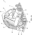
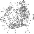
Figures 1a-1d show a perspective view from a front side, a perspective view from a rear side, a rear side view showing a first pivot point, and a rear side view showing a second pivot point respectively of a circular plunge saw according to an embodiment of the present invention; -
Figure 2 is an enlarged view of an inner guard portion of the tool showing arc guide means to allow different operational modes of the tool to be selected; -
Figures 3a-3b illustrate a partial view of a guard for the tool showing the mode selection pin and locking pin in a start position and an end position of the tool in a plunge mode respectively; -
Figures 4a-4b illustrate a partial view of a guard for the tool showing the mode selection pin and locking pin in an end position when the tool is in a scribe mode, and a view from the side of the tool in the same mode respectively; -
Figures 5a-5c illustrate a partial view of a guard for the tool showing the mode selection pin and locking pin in a blade change mode, a view from the side of the tool, and a partially exploded view from the side of the tool in the blade changing mode respectively; -
Figure 6 illustrates a partial view of the tool body from above showing a lock release lever; -
Figures 7a-7b illustrate a track compensation mechanism in one embodiment of the present invention in an "out of use" position and in an "in use" position respectively; -
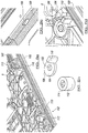
Figures 8a-8d show a perspective detailed view of a fine adjustment mechanism from the rear when the base plate of the tool is attached to a track in use; an exploded view of the fine adjustment mechanism; a side view from the front and a partial view of the fine adjustment mechanism respectively; -
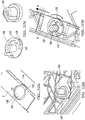
Figures 9a-9c illustrate a perspective view of a track lock in one embodiment of the present invention for locking the base plate of the tool to a track in use, a partial perspective view and an exploded view of the track lock respectively; and -
Figures 10a-10d illustrate a perspective view from above of an anti-kick back mechanism in one embodiment of the present invention to ensure the tool body only moves in one direction when the base plate is engaged on a track in use, a view from the base , an exploded view, and a partial view from above of the anti-kick back mechanism respectively. - Referring firstly to
figures 1a-1d , there is shown a powered circular plunge saw 2 including atool body 4 and abase plate 6 for supporting the tool body on a workpiece or surface in use. - A
circular saw blade 8 is attached to thetool body 4 and has suitable drive means in the form of amotor 10 located in the tool body for driving rotation of the saw blade in use. Power means in the form of a battery pack (not shown) forms part of thetool body 4 to provide power to the drive means. - A
guard 12 is provided around a substantial part of the saw blade to prevent a user from cutting themselves on the blade and includes an inner guard portion 14 (facing the tool body) and an outer guard portion 16 (facing away from the tool body). A workingaperture 18 is provided adjacent the base ofguard 12 to allow a working part of the saw blade to protrude therethrough in use. Ablade changing window 20 is provided onouter guard portion 16 to allow a user to change the saw blade when the tool is located in a blade changing mode (as described in more detail below). - The
tool body 4 has afirst handle portion 22 and asecond handle portion 24 to allow a user to grip the tool body in use with both hands in a safe and controlled manner. Acontrol switch 26 is provided onhandle portion 22 to allow the tool to be moved between "on" and "off" conditions. First andsecond handle portions - The
tool 2 has three operating modes; a plunge mode, wherein the saw blade can be moved to a required depth of cut selected by the user (typically up to a maximum of 55m), a scribe mode, wherein the saw blade can be moved to a more limited depth of cut (typically up to a maximum of 3mm); and a blade change mode, wherein the tool body is moved to a position where the attachment for the saw blade is accessible to a user to allow a blade to be changed. - A
distance measurement ruler 28 is provided oninner guard portion 14 to allow the required depth of cut to be set for when the tool is in the plunge mode. Anangle measurement indication 30 is providedadjacent base plate 6 to allow a bevel angle to be measured and set. On both measurement indicators/ruler screw 32 are typically provided to allow a required measurement to be set by the user in use. - The
tool body 4 and sawblade 8 are capable of being pivoted about a first pivotal axis 34 (a substantially horizontal axis) to allow the tool body to be moved between the blade changing mode, the scribe mode and the plunge mode. In pivotingtool body 4 to a cutting position, handle 24 is moved from a raised position, as shown infigure 1c , towardsbase plate 6, to a lowered position, as shown infigure 1b . The tool body has biasing means to bias the tool body to the raised position. Thus, the tool automatically moves back from a cutting position to a start or non-cutting position when a user removes their grip onhandles - The
tool body 4, sawblade 8 andguard 12 are capable of pivotal motion about a secondpivotal axis 36 to allow bevel cuts to be made using the tool, as shown infigure 1d . Thus, the tool body and guard are pivoted outwardly with respect tobase plate 6. Secondpivotal axis 36 is a substantially horizontal axis and is substantially perpendicular to firstpivotal axis 34. In this embodiment, twoupstanding support plates 38 are provided onbase plate 6.Curved slots 40 are defined in saidsupport plates 38 to guide the outwardly pivoting movement of thetool body 4 andguard 12 with respect tobase plate 6. Bolt and lockingnuts base plate 6. - In accordance with the present invention, the
tool 2 is provided with mode selection means that allows a single mode selection means to select one of the three different operational modes (i.e. the plunge mode, blade change mode and scribe mode). This ensures that only one operational mode can be selected by a user at any one time. - Guide means in the form of four slots or
channels inner guard portion 12. The channels 44-50 are in the form of arcs of a circle, they are substantially concentric to each other and have different length radii from a shared central point (i.e. they are a spaced distance apart). Each channel is joined to an adjacent channel by a joiningportion - The
outermost channel 44 is for the blade changing mode; theadjacent channel 46 is for the plunge mode (which is the longest arc); the next adjacent channel 48 (which is the shortest arc) is for the scribe mode; and the innermost channel is for location of a lockingpin 58 when a mode selection pin is located in the blade changing arc, as will be described in more detail below. - The depths of the channels 44-50 and joining portions 52-56 are of substantially uniform depth, apart from joining
portion 56 andfar end 59 ofchannel 50 where the depth of the same is deeper, as will be described in mote detail below. - The mode selection means includes a
mode selection pin 60 that is provided on anend 62 of arotatable cylinder 64, which in turn is rotatably mounted ontool body 4.End 62 ofcylinder 64 faces towardsouter guard portion 16.Pin 60 is located within the outer circumference of the cylinder adjacent a circumferential edge thereof. -
Mode selection pin 60 is slidably movable in channels 44-50 and joining portions 52-54. The tool body, and thus the saw blade, follows the movement of theselection pin 60 in said channels and joining portions. As such, the saw blade can be moved to required positions corresponding to the different operational modes on movement of themode selection pin 60. Rotation of therotatable cylinder 64 causes movement ofmode selection pin 60 between the concentric arcs and between the curved joining portions 52-54. Pivotal movement of the tool body with respect to the base plate movesmode selection pin 60 along the length of the arcs. - User selection means in the form of a
switch lever 66 extends outwardly from an outer surface ofrotatable cylinder 64 to allow a user to select a required mode of operation.Mode indication markings 68 can be provided on the tool body to indicate to a user when a required mode of operation has been selected. - A locking
pin 58 is associated withrotatable cylinder 64 such that lockingpin 58 follows movement of themode selection pin 60. More particularly, lockingpin 58 is driven by movement ofcylinder 64. The longitudinal axis ofpin 58 is substantially parallel to the longitudinal axis ofmode selection pin 60 andcylinder 64. Furthermore, the lockingpin 58 is concentric withcylinder 64, as ismode selection pin 60. The lockingpin 58 is resiliently biased towardsouter guard portion 16 to allow a locked position to be provided. Thus, lockingpin 58 can extend further towardsouter guard portion 16 compared tomode selection pin 60. As such, when lockingpin 58 is moved over an area of a channel 44-50 or joining portion 52-56 that has greater depth than the remaining area of the channel or joining portion, the lockingpin 58 locates in the deeper region and forms a locked position. Thetool body 4, sawblade 8 andmode selection pin 60 cannot then be moved further until the lockingpin 58 is moved to an unlocked position. - With reference to
figure 6 , there is illustrated a lock release lever orbutton 70 onhandle 22 that must be depressed by a user to move lockingpin 58 against its biasing force and away fromguard 12, from a locked position to an unlocked or release position.Button 70 is connected to lockingpin 58 through a mechanism provided in the tool body, such that depression oflever 70 moves the lockingpin 58 away fromguard 12 and back towardstool body 4, thereby moving the locking pin out of a deeper locking recess defined in channels 44-50 or joining portions 52-56. - A
shaft lock lever 72 is provided ontool 2 to lock the shaft of the saw blade in place so that the blade can be changed when the tool is in a blade changing mode. - With reference to
figures 3a-3b , there is illustrated a start and end position ofmode selection pin 60 and lockingpin 58 in the plunge mode respectively. The start position of the plunge mode is typically a default mode the tool body takes when resiliently biased to a non-cutting position. In this start position, the mode selection pin is located inchannel 46 adjacent joiningportions portions mode selection pin 60 to be easily moved into either portion from the default position. The lockingpin 58 is a spaced distance apart behindpin 60 and is located at anend 74 of joiningportion 56 andchannel 46. The recess of joiningportion 56 is deeper thanchannel 46 and so the tool body is locked in this position until a user moves lockingbutton 70 to an unlocked position. A user is then able to movetool body 4 towardsbase plate 6, thereby slidingmode selection pin 60 alongchannel 46 to a required depth of cut. The maximum limit of the depth of cut is determined by thepin 60 engaging with theend 76 ofchannel 46. A user selected depth of the cut less than the maximum limit is set as a result of the user moving the position ofpointer 88 provided on thedistance measurement ruler 28 to a required depth of cut, and possibly utilising the track compensation mechanism, as is described in more detail below with reference tofigures 7a-7b . If a user releases their grip on the tool body, the tool body is resiliently biased back to a non-cutting position and themode selection pin 60 and locking 58 move in reverse. - With reference to
figures 4a-4b , there is illustrated a position ofmode selection pin 60 and lockingpin 58 in the scribe mode. Themode selection lever 66 is first moved to the next indication marking 68 on the tool body corresponding to the scribe mode. The tool body is then pivotally moved relative tobase plate 6 under control of the user. This allowsmode selection pin 60 to be moved to end 78 ofchannel 48 and the lockingpin 58 is moved to channel 46 at the opening of joiningportions channel 48, typically corresponding to a depth of cut of 3mm, which is much shorter than the length ofchannel 46 used for the plunge mode, which typically corresponds to a maximum depth of cut of 55mm. -
Figure 4a also shows how a curved orarc slot 80 defined ininner guard 14, which allows slidable movement of the saw blade attachment means therein in use, part of which is shown as anarbour bolt 82 in this embodiment, is concentric with arc channels 44-50. As such, thesaw blade 8 andtool body 4 follow a similar motion tomode selection pin 60 in moving between the different operational modes. - With reference to
figures 5a-5c , there is illustrated a position of themode selection pin 60 and lockingpin 58 in the blade changing mode. Themode selection pin 60 is moved intooutermost channel 44 and, in doing so, lockingpin 58 is moved along joiningportion 56 and intoinnermost channel 50. Whenmode selection pin 60 contacts end 84 ofchannel 44, lockingpin 58 engages in the deeper recess provided atend 59 ofchannel 50 to form a locked position, thereby locking the saw blade andmode selection pin 60 in position. In this locked position,arbour bolt 82 isadjacent window 20 ofouter guard portion 16 to allow changing of thesaw blade 8. The blade, tool body andmode selection pin 60 cannot be moved untillock release button 70 is actuated to move the locking pin from a locked position to an unlocked position. In addition, the user actuatable "on"/"off" switch is in an interlocked position (i.e. cannot be operated) until the lock release button is actuated. In the other operational modes, the arbour bolt is not accessible throughwindow 20, thereby preventing removal of the blade unless the tool is in the correct blade changing mode. -
Figures 7a-7b illustrate a track compensation mechanism for use with the tool when the tool is not being used on a track. Circular plunge saws can be used on a track to maintain alignment of the saw in use or can be used directly on a workpiece. When the saw is placed on a track, the available cutting depth of the saw blade into a workpiece is reduced by the thickness of the track. For example, the saw is raised a pre-determined distance above the workpiece when placed on the track, which in turn is placed on a top surface of a workpiece.Distance measurement ruler 28 on a conventional tool does not take the difference the track thickness makes to the measured depth of cut into account. As such, when a user measures a depth of cut on a conventional distance measurement ruler, it can be up to 5mm out of position. However, the track compensation mechanism of the present invention does take the depth of a standard track the tool would normally be used on into consideration. A lockingnut 86 is provided, which has a required depth ofcut pointer 88 associated with the same, for allowing a user to set a required depth of cut with respect to distancemeasurement ruler 28. A top surface of the depth ofcut pointer 88 acts as astop surface 89 for astop rib 90 associated with thetool body 4. In normal operation oftool 2 on a track, as thetool body 4 is pivotally moved towardsbase plate 6 in the plunge cut mode, thestop rib 90 on thetool body 4 engages againststop surface 89 onpointer 88, thereby preventing further travel oftool body 4 towardsbase plate 6. The length of saw blade protruding through the workingaperture 18 ofguard 12 corresponds to the selected depth of cut shown bypointer 88 onmeasurement ruler 28. - If the
tool 2 is not used on a track, astop protrusion 91 is pivotably movable with respect to stopsurface 89 ofpointer 88 from a retracted position, wherein it is retracted in a slot defined instop surface 89, through 180 degrees to an extended position, where it protrudes upwardly frompointer 88 towardstool body 4. Thestrop protrusion 91 is of a pre-determined height corresponding to the thickness of the track, as shown infigure 7b . As such, as thetool body 4 is pivotally moved towardsbase plate 6 in the plunge cut mode, thestop rib 90 engages againststop protrusion 91 in the extended position. Thus, the required depth of cut provided by the saw blade is as set bypointer 88 on the measurement ruler rather than being an incorrect amount as with conventional tools. The method of the present invention does not rely on a user having to calculate the depth of track and taking this into account when setting the required depth of cut on the measurement ruler. -
Figures 8a-8d show afine adjustment mechanism 102 for use on thebase plate 6 of atool 2 when placed on atrack 100 in one embodiment of the present invention. Thefine adjustment mechanism 102 allows thebase plate 6 of the tool to be moved into increased contact withtrack 100 to prevent any unnecessary movement of the tool with respect to the track and to align the plunge saw correctly on the track. - The
fine adjustment mechanism 102 includes alever 104 having anaperture 105 that is rotatably mounted over asleeve member 106 protruding upwardly frombase plate 6. An outer side wall oflever 104 is provided with acam surface 108. Thiscam surface 108 is arranged to protrude through an aperture defined in a profiled portion ofbase plate 6 such that it can engage with an upwardly protruding portion oftrack 100, as shown infigure 8c . Rotation oflever 104 usinguser actuation portion 110 causes saidcam surface 108 to move into and out of engagement withtrack 100 as required, Atop member 112 sits on top oflever 104 and provides a locking means for lockinglever 104 in position. Thetop member 112 is typically in the form of a locking knob with a threaded portion. Apin 114 is aligned with and engages insleeve 106 to fix thetop member 112 to lever 104 andbase plate 6. - In a preferred embodiment two fine adjustment mechanisms are provided, one at the front of the base plate and one at the rear of the base plate.
-
Figures 9a-9c illustrate atrack lock 116 in one embodiment of the present invention for locking thebase plate 6 of thetool 2 to thetrack 100 when the tool is being used to make a bevel cut. Thetrack lock 116 includes a lockinglever 118 having an upwardlyprotruding sleeve member 120 provided thereon for location through anaperture 122 defined inbase plate 6. The lockinglever 118 has acam surface 124 that engages in achannel 126 defined on thetrack 100. A rotatableuser actuation knob 128 engages withsleeve member 120, such that rotation ofknob 128 causescam surface 124 to move into and out of engagement withtrack 100. Theknob 128 can be resiliently biased to a locked position by a spring. -
Figures 10a-10d illustrate ananti-kick back mechanism 130 in one embodiment of the present invention to ensure the tool body only moves in one direction when the base plate is engaged on a track in use. - The
mechanism 130 includes alower lever portion 132 that is rotatably mounted onbase plate 6 via asleeve portion 134 that protrudes upwardly through an aperture defined inbase plate 6. Thebase 136 oflower lever portion 132 is substantially flush withbase plate 6. A plurality ofteeth 138 are provided on aside wall 140adjacent base 136 and protrude through anaperture 142 defined in a profiled portion ofbase 136 so as to engage with a side oftrack 100 in use. The teeth allow travel of thelever portion 132 against thetrack 100 in a first direction only in use. Aspring 144 is provided to biaslower lever portion 132 back to an engaged position (i.e. where the teeth protrude throughaperture 142 so as to engage with a track in use) from a disengaged position (i.e. where the teeth are rotated out of engagement with the track against the biasing force of spring 144). Arotatable knob 146 engages withsleeve portion 134 to allow a user to rotate knob to move theteeth 138 to a disengaged position to allow the tool to be located on the track in use. - Thus, when the tool is moving in direction A along the track, as shown in
figure 10d , any kickback from the tool during the cutting process is prevented as a result ofteeth 138 engaging the track and preventing movement of the tool in the opposite direction to A. - It will be appreciated by persons skilled in the art that any or any combination of the mechanisms shown in 7a-10d could be used on any circular saw.
Claims (15)
- A powered circular saw tool (2), said tool (2) including a tool body (4), attachment means for allowing a circular saw blade (8) to be attached to the tool body (4) in use, and a base plate (6) associated with the tool body (4) for supporting the tool body (4) on a workpiece or surface in use, said tool body (4) arranged such that it is capable of undergoing pivotal movement relative to said base plate (6) to allow a circular saw blade (8) to be pivoted to a required depth of cut with respect to a workpiece in use, said tool (2) including two or more different operational modes that can be selected by a user in use; guide means are provided on the tool to guide the movement of the tool body relative to the base plate (6) in each of the different operational modes; and wherein a single mode selection means is provided for allowing selection of the different operational modes for each different operational mode, at least part of the single mode selection means movable with respect to the guide means in moving the tool body (4) between the different operational modes; wherein the guide means is in the form of at least one slot, recess, channel (44, 46, 48, 50) and/or aperture, and the single mode selection means is in the form of at least one selection pin (60) movably mounted in said at least one slot, recess, channel (44, 46, 48, 50) and/or aperture;
the at least one selection pin (60) is capable of undergoing rotational movement or is arranged to follow movement through at least a partially circular path to allow movement of the at least one selection pin (60) between different slots, recesses, channels (44, 46, 48, 50) and/or apertures;
wherein locking means are provided to lock the single mode selection means in a particular selected operational mode in use;
characterised in that the locking means includes a locking pin (58) provided a spaced distance apart from said selection pin (60) on said tool (2);
the locking pin (58) arranged to substantially follow movement of the selection pin (60) in use. - A tool according to claim 1 wherein the slot, recess, channel (44, 46, 48, 50) and/or aperture is in the shape of at least one arc.
- A tool according to claim 2 wherein two or more arcs are provided, each arc corresponding to each of two or more different operational modes of the tool (2); or at least three arcs are provided, each arc corresponding to each of three different operational modes of the tool (2); or four arcs are provided that correspond to three different operational modes of the tool (2).
- A tool according to claim 2, wherein two or more arcs are provided and the arcs have one or more of the following features: the arcs are arranged substantially concentrically, with each arc having a different radius from a central point to provide the arcs in a spaced apart arrangement; the length of each arc is substantially different; the arc corresponding to a plunge mode operational position of the tool (2) is longer in length relative to the arc corresponding to a scribe mode of the tool (2); the two or more arcs are provided a spaced distance apart from each other, adjacent arcs communicating via at least one joining portion (52, 54, 56); and the arc corresponding to a blade change operational mode of the tool (2) is the outermost arc relative to the tool base plate (6).
- A tool according to claim 1 wherein at least part of the attachment means for the saw blade (8) is slidably mounted in a slot (80), channel, recess or aperture defined in at least a portion of a guard (12) provided for the saw blade in use.
- A tool according to any preceding claim wherein the guard slot (8), channel, recess or aperture is arranged substantially concentrically with respect to the tool mode selection arcs.
- A tool according to claim 1 wherein the tool (2) is provided with a guard (12) for the saw blade (8), said guard (12) including an inner guard portion (14) and an outer guard portion (16), the saw blade (8) being located between the inner and outer guard portions (14, 16) in use.
- A tool according to any preceding claim wherein one of the guide means and the single mode selection means is provided on the inner guard portion (14) and the other of the guide means and the single mode selection means is provided on or associated with the tool body (4).
- A tool according to claim 1 wherein the selection pin (60) is integral with or attached to a rotatable member or cylinder (64), rotation of the rotatable member or cylinder (64) causing rotational movement of the selection pin (60) or movement of the selection pin (60) through at least a partially circular path in use, and the locking pin (58) is associated with the rotatable member or cylinder (64), such that movement of the rotatable member or cylinder (64) and selection pin (60) causes corresponding movement of the locking pin (58).
- A tool according to claim 9 wherein the locking pin (58) and the selection pin (60) are arranged substantially concentrically of the rotatable cylinder (64) or member, with the locking pin (58) having a different radius to that of the selection pin (60).
- A tool according to claim 1 wherein biasing means are associated with the locking means to bias the locking means to a locked position in use.
- A tool according to claim 11 wherein user actuation means are associated with the locking means to allow a user to move the locking means to an unlocked position in use.
- A tool according to any preceding claim wherein user actuation means are associated with the rotatable cylinder (64) or member or the single mode selection means to allow a user to select one of the two or more different operational modes of the tool (2).
- A tool according to any preceding claim wherein the joining portions (52, 54, 56) are in the form of channels or recesses and the depths of the channels or recesses in one or more parts of the arcs and/or joining portions (52, 54, 56) are different to allow location of the locking pin (58) therein to form a locked position.
- A method of using a powered circular saw tool (2), said tool including a tool body (4), attachment means for allowing a circular saw blade (8) to be attached to the tool body (4) in use, and a base plate (6) associated with the tool body (4) for supporting the tool body (4) on a workpiece or surface in use, said tool body (4) arranged such that it is capable of undergoing pivotal movement relative to said base plate (6) to allow a circular saw blade (8) to be pivoted to a required depth of cut with respect to a workpiece in use, said method including the step of selecting an operational mode for the tool (2) from two or more different selectable tool operational modes, guide means are provided on the tool to guide the movement of the tool body (4) relative to the base plate (6) in each of the different operational modes; and wherein a single mode selection means is provided for allowing the selection of the different operational modes for each different operational mode; said method further including the steps of moving the single mode selection means, in the form of at least one selection pin (60), with respect to the guide means, in the form of at least one slot, recess, channel (44, 46, 48, 50) and/or aperture, in moving the tool body (4) between the different operational modes; the at least one selection pin (60) undergoing rotational movement or following movement through at least a partially circular path in moving between different slots, recesses, channels (44, 46, 48, 50) and/or apertures;
locking the single mode selection means in a particular selected operational mode using locking means;
characterised in that the locking means including a locking pin (58) provided a spaced distance apart from said selection pin (60) and substantially following movement of the selection pin (60) in use.
Applications Claiming Priority (2)
| Application Number | Priority Date | Filing Date | Title |
|---|---|---|---|
| GBGB1102368.6A GB201102368D0 (en) | 2011-02-10 | 2011-02-10 | Powered circular saw and method of use thereof |
| PCT/GB2012/050282 WO2012107764A1 (en) | 2011-02-10 | 2012-02-09 | Powered circular saw and method of use thereof |
Publications (2)
| Publication Number | Publication Date |
|---|---|
| EP2673123A1 EP2673123A1 (en) | 2013-12-18 |
| EP2673123B1 true EP2673123B1 (en) | 2020-02-19 |
Family
ID=43859241
Family Applications (1)
| Application Number | Title | Priority Date | Filing Date |
|---|---|---|---|
| EP12704537.5A Active EP2673123B1 (en) | 2011-02-10 | 2012-02-09 | Powered circular saw and method of use thereof |
Country Status (7)
| Country | Link |
|---|---|
| US (1) | US9242390B2 (en) |
| EP (1) | EP2673123B1 (en) |
| CN (1) | CN103459106B (en) |
| AU (1) | AU2012215197B2 (en) |
| CA (1) | CA2830340C (en) |
| GB (1) | GB201102368D0 (en) |
| WO (1) | WO2012107764A1 (en) |
Families Citing this family (16)
| Publication number | Priority date | Publication date | Assignee | Title |
|---|---|---|---|---|
| GB201102368D0 (en) * | 2011-02-10 | 2011-03-30 | 7Rdd Ltd | Powered circular saw and method of use thereof |
| CN106424920A (en) * | 2012-07-13 | 2017-02-22 | 苏州宝时得电动工具有限公司 | Portable cutting machine |
| US9707693B2 (en) * | 2015-03-06 | 2017-07-18 | Chao-Ying LEE | Self-contained docking arrangement for head saw machine |
| CN105269618A (en) * | 2015-10-28 | 2016-01-27 | 林蓉瑶 | First-aid cutting machine quantification device |
| USD821957S1 (en) * | 2015-12-04 | 2018-07-03 | Ningbo Jingcheng Car Industry Co, Ltd | Electric foldable device of rearview mirror for automobiles |
| CN106002575A (en) * | 2016-07-16 | 2016-10-12 | 方小玲 | High-precision cutting machine |
| WO2018123366A1 (en) * | 2016-12-28 | 2018-07-05 | 工機ホールディングス株式会社 | Portable cutter |
| US10875109B1 (en) | 2018-04-30 | 2020-12-29 | Kreg Enterprises, Inc. | Adaptive cutting system |
| DE102019003733B4 (en) * | 2019-05-28 | 2023-05-25 | Metabowerke Gmbh | Hand machine tool and method for changing a working tool of a hand machine tool |
| DE102019134411A1 (en) * | 2019-12-13 | 2021-06-17 | Festool Gmbh | Mobile hand sawing machine with a swiveling scoring unit |
| USD951051S1 (en) | 2020-01-02 | 2022-05-10 | Techtronic Cordless Gp | Circular saw |
| US12208457B2 (en) | 2020-01-02 | 2025-01-28 | Techtronic Cordless Gp | Circular saw |
| EP4171856B1 (en) * | 2020-06-25 | 2025-07-30 | Festool GmbH | Plunge saw with cut indicators and method of operating a plunge saw |
| US12263615B2 (en) | 2020-11-23 | 2025-04-01 | Milwaukee Electric Tool Corporation | Circular saw |
| US12465982B2 (en) * | 2022-02-24 | 2025-11-11 | Techtronic Cordless Gp | Track saw including plunge lockout mechanism |
| US12083613B2 (en) | 2022-10-18 | 2024-09-10 | Techtronic Cordless Gp | Track saw including plunge lockout mechanism |
Family Cites Families (29)
| Publication number | Priority date | Publication date | Assignee | Title |
|---|---|---|---|---|
| US3262472A (en) * | 1964-05-08 | 1966-07-26 | Black & Decker Mfg Co | Depth and bevel adjustment means for portable power-driven saw |
| US4221051A (en) * | 1979-05-30 | 1980-09-09 | The Singer Company | Circular saw with improved base plate adjustment |
| US4856394A (en) * | 1988-04-14 | 1989-08-15 | Porter-Cable Corporation | Portable circular saw |
| JPH0737782Y2 (en) * | 1989-12-15 | 1995-08-30 | 日立工機株式会社 | Electric circular saw base tilting mechanism |
| DE4001331A1 (en) * | 1990-01-18 | 1991-07-25 | Reich Maschf Gmbh Karl | Cutting coated wooden etc. workpieces by circular saw - cuts cover layer in two orthogonal directions, and then entire cross=section in opposite cuts |
| DE4124232A1 (en) * | 1991-07-22 | 1993-01-28 | Bosch Gmbh Robert | HAND CIRCULAR SAW, IN PARTICULAR DIVING SAW |
| DE4124233A1 (en) * | 1991-07-22 | 1993-01-28 | Bosch Gmbh Robert | Circular saw |
| DE4300033B4 (en) * | 1993-01-02 | 2005-02-24 | Robert Bosch Gmbh | Hand circular saw with bevel angle adjustment device |
| US5433008A (en) * | 1994-01-31 | 1995-07-18 | Porter-Cable Corporation | Circular saw with variable adjustment stops |
| DE4403189B4 (en) * | 1994-02-02 | 2006-01-12 | Robert Bosch Gmbh | Circular saw with pendulum protection hood and with a cutting depth adjustment device |
| US5950514A (en) * | 1997-02-28 | 1999-09-14 | Benedict Engineering Company | Miter saw blade guards |
| US5758425A (en) * | 1997-05-20 | 1998-06-02 | S-B Power Tool Company | Depth-of-cut mechanism for circular saw |
| DE19923145A1 (en) * | 1999-05-20 | 2000-11-23 | Hilti Ag | Suction hood for hand-held cutters |
| DE10032294B4 (en) * | 2000-07-03 | 2005-10-13 | Hilti Ag | Machine tool for cutting work |
| JP4283464B2 (en) * | 2001-08-02 | 2009-06-24 | 株式会社マキタ | Marunoco |
| JP3888165B2 (en) * | 2002-01-16 | 2007-02-28 | 日立工機株式会社 | Portable cutting machine |
| US6735875B1 (en) * | 2002-05-22 | 2004-05-18 | At&T Corp. | Tool for removing duct surrounding a fiber optic cable |
| DE10261743A1 (en) * | 2002-12-30 | 2004-07-22 | Robert Bosch Gmbh | Manual circular saw B27B |
| DE10303543B4 (en) * | 2003-01-29 | 2015-09-10 | Robert Bosch Gmbh | Hand tool |
| US7290342B2 (en) * | 2004-01-16 | 2007-11-06 | Robert Bosch Gmbh | Bevel and depth of cut detent system |
| US20080244910A1 (en) * | 2004-05-28 | 2008-10-09 | Scientific Molding Corporation Ltd. | Hand-Held Circular Saw, In Particular Plunge-Cut Saw |
| JP4954504B2 (en) * | 2005-06-28 | 2012-06-20 | 株式会社マキタ | Portable circular saw |
| JP4780524B2 (en) * | 2006-02-22 | 2011-09-28 | 日立工機株式会社 | Portable cutting machine |
| US8061043B2 (en) * | 2006-11-15 | 2011-11-22 | Milwaukee Electric Tool Corporation | Power tool |
| GB0719802D0 (en) * | 2007-10-04 | 2007-11-21 | Black & Decker Inc | A Power tool |
| JP5398993B2 (en) * | 2008-02-05 | 2014-01-29 | 株式会社マキタ | Cutting machine body |
| CN102114555B (en) * | 2010-01-04 | 2014-05-28 | 泉峰(中国)贸易有限公司 | Electric tool |
| GB201003262D0 (en) * | 2010-02-26 | 2010-04-14 | 7Rdd Ltd | Saw guard means and method of use thereof |
| GB201102368D0 (en) * | 2011-02-10 | 2011-03-30 | 7Rdd Ltd | Powered circular saw and method of use thereof |
-
2011
- 2011-02-10 GB GBGB1102368.6A patent/GB201102368D0/en not_active Ceased
-
2012
- 2012-02-09 AU AU2012215197A patent/AU2012215197B2/en active Active
- 2012-02-09 EP EP12704537.5A patent/EP2673123B1/en active Active
- 2012-02-09 CN CN201280017575.3A patent/CN103459106B/en active Active
- 2012-02-09 CA CA2830340A patent/CA2830340C/en active Active
- 2012-02-09 WO PCT/GB2012/050282 patent/WO2012107764A1/en not_active Ceased
-
2013
- 2013-08-08 US US13/962,134 patent/US9242390B2/en active Active
Non-Patent Citations (1)
| Title |
|---|
| None * |
Also Published As
| Publication number | Publication date |
|---|---|
| CA2830340C (en) | 2020-03-10 |
| WO2012107764A1 (en) | 2012-08-16 |
| AU2012215197A1 (en) | 2013-10-03 |
| CA2830340A1 (en) | 2012-08-16 |
| AU2012215197B2 (en) | 2015-12-24 |
| GB201102368D0 (en) | 2011-03-30 |
| CN103459106B (en) | 2016-10-26 |
| CN103459106A (en) | 2013-12-18 |
| US9242390B2 (en) | 2016-01-26 |
| EP2673123A1 (en) | 2013-12-18 |
| US20130318801A1 (en) | 2013-12-05 |
Similar Documents
| Publication | Publication Date | Title |
|---|---|---|
| AU2012215197B2 (en) | Powered circular saw and method of use thereof | |
| CN101402173B (en) | A power tool | |
| US7900661B2 (en) | Plunge router and kit | |
| US20250214275A1 (en) | Track saw assembly | |
| EP2771148B1 (en) | Planer accessory tool for an oscillating power tool | |
| US6757982B2 (en) | Safety improvements for power tool | |
| US20120204430A1 (en) | Undercut saw height adjustment, handle, blade guard improvements | |
| US20050060896A1 (en) | Clamping apparatus for a tool component and an improved scrolling mechanism | |
| GB2476713A (en) | Power tool with push and insert modes | |
| CA2697590C (en) | Laminate flooring saw | |
| US8302518B2 (en) | Laminate flooring saw | |
| CN223264879U (en) | Circular saw and orbital saw assembly configured to cut in a workpiece | |
| EP3479942A1 (en) | Cutting tool | |
| JP4796285B2 (en) | Portable cutting tools | |
| WO2011104538A1 (en) | Guard means for a saw and method of use thereof | |
| US20250339991A1 (en) | Prescoring tool for a sawing machine | |
| EP2591898B1 (en) | Chop saw with top table | |
| US20230264275A1 (en) | Track saw including plunge lockout mechanism | |
| WO2011042733A1 (en) | Guide means for a cutting tool and method of use thereof | |
| EP1514626B1 (en) | Shoe assembly for power tool and power tool incorporating such assembly | |
| US20010055519A1 (en) | Right-angle plunge router | |
| JP2003251604A (en) | Motor-driven tool | |
| JP2023114186A (en) | portable processing machine | |
| JP2007167982A (en) | Electric cutting tool | |
| AU2003248455A1 (en) | Clamping apparatus for a tool component and an improved scrolling mechanism |
Legal Events
| Date | Code | Title | Description |
|---|---|---|---|
| PUAI | Public reference made under article 153(3) epc to a published international application that has entered the european phase |
Free format text: ORIGINAL CODE: 0009012 |
|
| 17P | Request for examination filed |
Effective date: 20130821 |
|
| AK | Designated contracting states |
Kind code of ref document: A1 Designated state(s): AL AT BE BG CH CY CZ DE DK EE ES FI FR GB GR HR HU IE IS IT LI LT LU LV MC MK MT NL NO PL PT RO RS SE SI SK SM TR |
|
| DAX | Request for extension of the european patent (deleted) | ||
| STAA | Information on the status of an ep patent application or granted ep patent |
Free format text: STATUS: EXAMINATION IS IN PROGRESS |
|
| 17Q | First examination report despatched |
Effective date: 20180905 |
|
| GRAP | Despatch of communication of intention to grant a patent |
Free format text: ORIGINAL CODE: EPIDOSNIGR1 |
|
| STAA | Information on the status of an ep patent application or granted ep patent |
Free format text: STATUS: GRANT OF PATENT IS INTENDED |
|
| INTG | Intention to grant announced |
Effective date: 20191021 |
|
| GRAS | Grant fee paid |
Free format text: ORIGINAL CODE: EPIDOSNIGR3 |
|
| GRAA | (expected) grant |
Free format text: ORIGINAL CODE: 0009210 |
|
| STAA | Information on the status of an ep patent application or granted ep patent |
Free format text: STATUS: THE PATENT HAS BEEN GRANTED |
|
| AK | Designated contracting states |
Kind code of ref document: B1 Designated state(s): AL AT BE BG CH CY CZ DE DK EE ES FI FR GB GR HR HU IE IS IT LI LT LU LV MC MK MT NL NO PL PT RO RS SE SI SK SM TR |
|
| REG | Reference to a national code |
Ref country code: GB Ref legal event code: FG4D |
|
| REG | Reference to a national code |
Ref country code: CH Ref legal event code: EP |
|
| REG | Reference to a national code |
Ref country code: DE Ref legal event code: R096 Ref document number: 602012067868 Country of ref document: DE |
|
| REG | Reference to a national code |
Ref country code: AT Ref legal event code: REF Ref document number: 1234415 Country of ref document: AT Kind code of ref document: T Effective date: 20200315 |
|
| REG | Reference to a national code |
Ref country code: IE Ref legal event code: FG4D |
|
| REG | Reference to a national code |
Ref country code: NL Ref legal event code: MP Effective date: 20200219 |
|
| PG25 | Lapsed in a contracting state [announced via postgrant information from national office to epo] |
Ref country code: RS Free format text: LAPSE BECAUSE OF FAILURE TO SUBMIT A TRANSLATION OF THE DESCRIPTION OR TO PAY THE FEE WITHIN THE PRESCRIBED TIME-LIMIT Effective date: 20200219 Ref country code: FI Free format text: LAPSE BECAUSE OF FAILURE TO SUBMIT A TRANSLATION OF THE DESCRIPTION OR TO PAY THE FEE WITHIN THE PRESCRIBED TIME-LIMIT Effective date: 20200219 Ref country code: NO Free format text: LAPSE BECAUSE OF FAILURE TO SUBMIT A TRANSLATION OF THE DESCRIPTION OR TO PAY THE FEE WITHIN THE PRESCRIBED TIME-LIMIT Effective date: 20200519 |
|
| REG | Reference to a national code |
Ref country code: LT Ref legal event code: MG4D |
|
| PG25 | Lapsed in a contracting state [announced via postgrant information from national office to epo] |
Ref country code: BG Free format text: LAPSE BECAUSE OF FAILURE TO SUBMIT A TRANSLATION OF THE DESCRIPTION OR TO PAY THE FEE WITHIN THE PRESCRIBED TIME-LIMIT Effective date: 20200519 Ref country code: GR Free format text: LAPSE BECAUSE OF FAILURE TO SUBMIT A TRANSLATION OF THE DESCRIPTION OR TO PAY THE FEE WITHIN THE PRESCRIBED TIME-LIMIT Effective date: 20200520 Ref country code: IS Free format text: LAPSE BECAUSE OF FAILURE TO SUBMIT A TRANSLATION OF THE DESCRIPTION OR TO PAY THE FEE WITHIN THE PRESCRIBED TIME-LIMIT Effective date: 20200619 Ref country code: LV Free format text: LAPSE BECAUSE OF FAILURE TO SUBMIT A TRANSLATION OF THE DESCRIPTION OR TO PAY THE FEE WITHIN THE PRESCRIBED TIME-LIMIT Effective date: 20200219 Ref country code: SE Free format text: LAPSE BECAUSE OF FAILURE TO SUBMIT A TRANSLATION OF THE DESCRIPTION OR TO PAY THE FEE WITHIN THE PRESCRIBED TIME-LIMIT Effective date: 20200219 Ref country code: HR Free format text: LAPSE BECAUSE OF FAILURE TO SUBMIT A TRANSLATION OF THE DESCRIPTION OR TO PAY THE FEE WITHIN THE PRESCRIBED TIME-LIMIT Effective date: 20200219 |
|
| PG25 | Lapsed in a contracting state [announced via postgrant information from national office to epo] |
Ref country code: NL Free format text: LAPSE BECAUSE OF FAILURE TO SUBMIT A TRANSLATION OF THE DESCRIPTION OR TO PAY THE FEE WITHIN THE PRESCRIBED TIME-LIMIT Effective date: 20200219 |
|
| PG25 | Lapsed in a contracting state [announced via postgrant information from national office to epo] |
Ref country code: SK Free format text: LAPSE BECAUSE OF FAILURE TO SUBMIT A TRANSLATION OF THE DESCRIPTION OR TO PAY THE FEE WITHIN THE PRESCRIBED TIME-LIMIT Effective date: 20200219 Ref country code: PT Free format text: LAPSE BECAUSE OF FAILURE TO SUBMIT A TRANSLATION OF THE DESCRIPTION OR TO PAY THE FEE WITHIN THE PRESCRIBED TIME-LIMIT Effective date: 20200712 Ref country code: SM Free format text: LAPSE BECAUSE OF FAILURE TO SUBMIT A TRANSLATION OF THE DESCRIPTION OR TO PAY THE FEE WITHIN THE PRESCRIBED TIME-LIMIT Effective date: 20200219 Ref country code: EE Free format text: LAPSE BECAUSE OF FAILURE TO SUBMIT A TRANSLATION OF THE DESCRIPTION OR TO PAY THE FEE WITHIN THE PRESCRIBED TIME-LIMIT Effective date: 20200219 Ref country code: DK Free format text: LAPSE BECAUSE OF FAILURE TO SUBMIT A TRANSLATION OF THE DESCRIPTION OR TO PAY THE FEE WITHIN THE PRESCRIBED TIME-LIMIT Effective date: 20200219 Ref country code: RO Free format text: LAPSE BECAUSE OF FAILURE TO SUBMIT A TRANSLATION OF THE DESCRIPTION OR TO PAY THE FEE WITHIN THE PRESCRIBED TIME-LIMIT Effective date: 20200219 Ref country code: LT Free format text: LAPSE BECAUSE OF FAILURE TO SUBMIT A TRANSLATION OF THE DESCRIPTION OR TO PAY THE FEE WITHIN THE PRESCRIBED TIME-LIMIT Effective date: 20200219 Ref country code: ES Free format text: LAPSE BECAUSE OF FAILURE TO SUBMIT A TRANSLATION OF THE DESCRIPTION OR TO PAY THE FEE WITHIN THE PRESCRIBED TIME-LIMIT Effective date: 20200219 Ref country code: CZ Free format text: LAPSE BECAUSE OF FAILURE TO SUBMIT A TRANSLATION OF THE DESCRIPTION OR TO PAY THE FEE WITHIN THE PRESCRIBED TIME-LIMIT Effective date: 20200219 |
|
| REG | Reference to a national code |
Ref country code: AT Ref legal event code: MK05 Ref document number: 1234415 Country of ref document: AT Kind code of ref document: T Effective date: 20200219 |
|
| REG | Reference to a national code |
Ref country code: DE Ref legal event code: R097 Ref document number: 602012067868 Country of ref document: DE |
|
| PLBE | No opposition filed within time limit |
Free format text: ORIGINAL CODE: 0009261 |
|
| STAA | Information on the status of an ep patent application or granted ep patent |
Free format text: STATUS: NO OPPOSITION FILED WITHIN TIME LIMIT |
|
| 26N | No opposition filed |
Effective date: 20201120 |
|
| PG25 | Lapsed in a contracting state [announced via postgrant information from national office to epo] |
Ref country code: IT Free format text: LAPSE BECAUSE OF FAILURE TO SUBMIT A TRANSLATION OF THE DESCRIPTION OR TO PAY THE FEE WITHIN THE PRESCRIBED TIME-LIMIT Effective date: 20200219 Ref country code: AT Free format text: LAPSE BECAUSE OF FAILURE TO SUBMIT A TRANSLATION OF THE DESCRIPTION OR TO PAY THE FEE WITHIN THE PRESCRIBED TIME-LIMIT Effective date: 20200219 |
|
| PG25 | Lapsed in a contracting state [announced via postgrant information from national office to epo] |
Ref country code: SI Free format text: LAPSE BECAUSE OF FAILURE TO SUBMIT A TRANSLATION OF THE DESCRIPTION OR TO PAY THE FEE WITHIN THE PRESCRIBED TIME-LIMIT Effective date: 20200219 Ref country code: PL Free format text: LAPSE BECAUSE OF FAILURE TO SUBMIT A TRANSLATION OF THE DESCRIPTION OR TO PAY THE FEE WITHIN THE PRESCRIBED TIME-LIMIT Effective date: 20200219 |
|
| PG25 | Lapsed in a contracting state [announced via postgrant information from national office to epo] |
Ref country code: MC Free format text: LAPSE BECAUSE OF FAILURE TO SUBMIT A TRANSLATION OF THE DESCRIPTION OR TO PAY THE FEE WITHIN THE PRESCRIBED TIME-LIMIT Effective date: 20200219 |
|
| REG | Reference to a national code |
Ref country code: BE Ref legal event code: MM Effective date: 20210228 |
|
| PG25 | Lapsed in a contracting state [announced via postgrant information from national office to epo] |
Ref country code: LI Free format text: LAPSE BECAUSE OF NON-PAYMENT OF DUE FEES Effective date: 20210228 Ref country code: LU Free format text: LAPSE BECAUSE OF NON-PAYMENT OF DUE FEES Effective date: 20210209 Ref country code: CH Free format text: LAPSE BECAUSE OF NON-PAYMENT OF DUE FEES Effective date: 20210228 |
|
| PG25 | Lapsed in a contracting state [announced via postgrant information from national office to epo] |
Ref country code: IE Free format text: LAPSE BECAUSE OF NON-PAYMENT OF DUE FEES Effective date: 20210209 |
|
| PG25 | Lapsed in a contracting state [announced via postgrant information from national office to epo] |
Ref country code: BE Free format text: LAPSE BECAUSE OF NON-PAYMENT OF DUE FEES Effective date: 20210228 |
|
| PG25 | Lapsed in a contracting state [announced via postgrant information from national office to epo] |
Ref country code: HU Free format text: LAPSE BECAUSE OF FAILURE TO SUBMIT A TRANSLATION OF THE DESCRIPTION OR TO PAY THE FEE WITHIN THE PRESCRIBED TIME-LIMIT; INVALID AB INITIO Effective date: 20120209 Ref country code: CY Free format text: LAPSE BECAUSE OF FAILURE TO SUBMIT A TRANSLATION OF THE DESCRIPTION OR TO PAY THE FEE WITHIN THE PRESCRIBED TIME-LIMIT Effective date: 20200219 |
|
| P01 | Opt-out of the competence of the unified patent court (upc) registered |
Effective date: 20230403 |
|
| PG25 | Lapsed in a contracting state [announced via postgrant information from national office to epo] |
Ref country code: MK Free format text: LAPSE BECAUSE OF FAILURE TO SUBMIT A TRANSLATION OF THE DESCRIPTION OR TO PAY THE FEE WITHIN THE PRESCRIBED TIME-LIMIT Effective date: 20200219 |
|
| PG25 | Lapsed in a contracting state [announced via postgrant information from national office to epo] |
Ref country code: TR Free format text: LAPSE BECAUSE OF FAILURE TO SUBMIT A TRANSLATION OF THE DESCRIPTION OR TO PAY THE FEE WITHIN THE PRESCRIBED TIME-LIMIT Effective date: 20200219 |
|
| PG25 | Lapsed in a contracting state [announced via postgrant information from national office to epo] |
Ref country code: MT Free format text: LAPSE BECAUSE OF FAILURE TO SUBMIT A TRANSLATION OF THE DESCRIPTION OR TO PAY THE FEE WITHIN THE PRESCRIBED TIME-LIMIT Effective date: 20200219 |
|
| PGFP | Annual fee paid to national office [announced via postgrant information from national office to epo] |
Ref country code: GB Payment date: 20260313 Year of fee payment: 15 |
|
| PGFP | Annual fee paid to national office [announced via postgrant information from national office to epo] |
Ref country code: DE Payment date: 20260316 Year of fee payment: 15 |
|
| PGFP | Annual fee paid to national office [announced via postgrant information from national office to epo] |
Ref country code: FR Payment date: 20260313 Year of fee payment: 15 |