EP2672938B1 - Stent for splinting a nasal passage - Google Patents
Stent for splinting a nasal passage Download PDFInfo
- Publication number
- EP2672938B1 EP2672938B1 EP12706453.3A EP12706453A EP2672938B1 EP 2672938 B1 EP2672938 B1 EP 2672938B1 EP 12706453 A EP12706453 A EP 12706453A EP 2672938 B1 EP2672938 B1 EP 2672938B1
- Authority
- EP
- European Patent Office
- Prior art keywords
- stent
- support body
- fixing
- holding element
- nasal passage
- Prior art date
- Legal status (The legal status is an assumption and is not a legal conclusion. Google has not performed a legal analysis and makes no representation as to the accuracy of the status listed.)
- Active
Links
- 238000003780 insertion Methods 0.000 claims description 87
- 230000037431 insertion Effects 0.000 claims description 87
- 238000010168 coupling process Methods 0.000 claims description 42
- 238000005859 coupling reaction Methods 0.000 claims description 42
- 230000008878 coupling Effects 0.000 claims description 39
- RVTZCBVAJQQJTK-UHFFFAOYSA-N oxygen(2-);zirconium(4+) Chemical compound [O-2].[O-2].[Zr+4] RVTZCBVAJQQJTK-UHFFFAOYSA-N 0.000 claims description 5
- 229910000831 Steel Inorganic materials 0.000 claims description 4
- 229910052751 metal Inorganic materials 0.000 claims description 4
- 239000002184 metal Substances 0.000 claims description 4
- 239000010959 steel Substances 0.000 claims description 4
- 210000001331 nose Anatomy 0.000 description 26
- 229920003023 plastic Polymers 0.000 description 26
- 210000001847 jaw Anatomy 0.000 description 17
- 239000000463 material Substances 0.000 description 16
- 210000002414 leg Anatomy 0.000 description 13
- 229920002614 Polyether block amide Polymers 0.000 description 12
- 208000008784 apnea Diseases 0.000 description 9
- 210000003928 nasal cavity Anatomy 0.000 description 9
- 210000003800 pharynx Anatomy 0.000 description 8
- 210000001944 turbinate Anatomy 0.000 description 7
- 210000002105 tongue Anatomy 0.000 description 6
- 240000007817 Olea europaea Species 0.000 description 4
- 230000009471 action Effects 0.000 description 3
- 230000008901 benefit Effects 0.000 description 3
- 230000000994 depressogenic effect Effects 0.000 description 3
- 230000000694 effects Effects 0.000 description 3
- 239000000835 fiber Substances 0.000 description 3
- 229920002457 flexible plastic Polymers 0.000 description 3
- 210000003254 palate Anatomy 0.000 description 3
- 206010041235 Snoring Diseases 0.000 description 2
- 230000015572 biosynthetic process Effects 0.000 description 2
- 238000009954 braiding Methods 0.000 description 2
- 238000002788 crimping Methods 0.000 description 2
- 230000006378 damage Effects 0.000 description 2
- 239000007788 liquid Substances 0.000 description 2
- 210000001989 nasopharynx Anatomy 0.000 description 2
- 229920001296 polysiloxane Polymers 0.000 description 2
- 210000001519 tissue Anatomy 0.000 description 2
- 230000007704 transition Effects 0.000 description 2
- 241000511343 Chondrostoma nasus Species 0.000 description 1
- 208000001705 Mouth breathing Diseases 0.000 description 1
- 229910000639 Spring steel Inorganic materials 0.000 description 1
- RTAQQCXQSZGOHL-UHFFFAOYSA-N Titanium Chemical compound [Ti] RTAQQCXQSZGOHL-UHFFFAOYSA-N 0.000 description 1
- 239000004480 active ingredient Substances 0.000 description 1
- 239000000853 adhesive Substances 0.000 description 1
- 238000004026 adhesive bonding Methods 0.000 description 1
- 230000001070 adhesive effect Effects 0.000 description 1
- 238000000137 annealing Methods 0.000 description 1
- 230000000295 complement effect Effects 0.000 description 1
- 239000000109 continuous material Substances 0.000 description 1
- 230000007423 decrease Effects 0.000 description 1
- 238000009826 distribution Methods 0.000 description 1
- 229920001971 elastomer Polymers 0.000 description 1
- 239000000806 elastomer Substances 0.000 description 1
- 238000001839 endoscopy Methods 0.000 description 1
- 238000001125 extrusion Methods 0.000 description 1
- 210000001214 frontal sinus Anatomy 0.000 description 1
- 238000000227 grinding Methods 0.000 description 1
- 238000010438 heat treatment Methods 0.000 description 1
- 238000000608 laser ablation Methods 0.000 description 1
- 238000004519 manufacturing process Methods 0.000 description 1
- 230000013011 mating Effects 0.000 description 1
- 238000002844 melting Methods 0.000 description 1
- 230000008018 melting Effects 0.000 description 1
- 238000000034 method Methods 0.000 description 1
- 238000000465 moulding Methods 0.000 description 1
- 210000000492 nasalseptum Anatomy 0.000 description 1
- 230000000149 penetrating effect Effects 0.000 description 1
- 239000011505 plaster Substances 0.000 description 1
- 239000004014 plasticizer Substances 0.000 description 1
- 229920000642 polymer Polymers 0.000 description 1
- 238000003825 pressing Methods 0.000 description 1
- 230000008569 process Effects 0.000 description 1
- 230000029058 respiratory gaseous exchange Effects 0.000 description 1
- 230000035945 sensitivity Effects 0.000 description 1
- 210000001584 soft palate Anatomy 0.000 description 1
- 239000007787 solid Substances 0.000 description 1
- 125000006850 spacer group Chemical group 0.000 description 1
- 238000002560 therapeutic procedure Methods 0.000 description 1
- 230000008719 thickening Effects 0.000 description 1
- 239000010936 titanium Substances 0.000 description 1
- 229910052719 titanium Inorganic materials 0.000 description 1
- 210000000689 upper leg Anatomy 0.000 description 1
Images


Classifications
-
- A—HUMAN NECESSITIES
- A61—MEDICAL OR VETERINARY SCIENCE; HYGIENE
- A61M—DEVICES FOR INTRODUCING MEDIA INTO, OR ONTO, THE BODY; DEVICES FOR TRANSDUCING BODY MEDIA OR FOR TAKING MEDIA FROM THE BODY; DEVICES FOR PRODUCING OR ENDING SLEEP OR STUPOR
- A61M29/00—Dilators with or without means for introducing media, e.g. remedies
- A61M29/02—Dilators made of swellable material
-
- A—HUMAN NECESSITIES
- A61—MEDICAL OR VETERINARY SCIENCE; HYGIENE
- A61F—FILTERS IMPLANTABLE INTO BLOOD VESSELS; PROSTHESES; DEVICES PROVIDING PATENCY TO, OR PREVENTING COLLAPSING OF, TUBULAR STRUCTURES OF THE BODY, e.g. STENTS; ORTHOPAEDIC, NURSING OR CONTRACEPTIVE DEVICES; FOMENTATION; TREATMENT OR PROTECTION OF EYES OR EARS; BANDAGES, DRESSINGS OR ABSORBENT PADS; FIRST-AID KITS
- A61F5/00—Orthopaedic methods or devices for non-surgical treatment of bones or joints; Nursing devices; Anti-rape devices
- A61F5/01—Orthopaedic devices, e.g. splints, casts or braces
- A61F5/08—Devices for correcting deformities of the nose ; Devices for enlarging the nostril, e.g. for breathing improvement
-
- A—HUMAN NECESSITIES
- A61—MEDICAL OR VETERINARY SCIENCE; HYGIENE
- A61F—FILTERS IMPLANTABLE INTO BLOOD VESSELS; PROSTHESES; DEVICES PROVIDING PATENCY TO, OR PREVENTING COLLAPSING OF, TUBULAR STRUCTURES OF THE BODY, e.g. STENTS; ORTHOPAEDIC, NURSING OR CONTRACEPTIVE DEVICES; FOMENTATION; TREATMENT OR PROTECTION OF EYES OR EARS; BANDAGES, DRESSINGS OR ABSORBENT PADS; FIRST-AID KITS
- A61F5/00—Orthopaedic methods or devices for non-surgical treatment of bones or joints; Nursing devices; Anti-rape devices
- A61F5/56—Devices for preventing snoring
-
- A—HUMAN NECESSITIES
- A61—MEDICAL OR VETERINARY SCIENCE; HYGIENE
- A61F—FILTERS IMPLANTABLE INTO BLOOD VESSELS; PROSTHESES; DEVICES PROVIDING PATENCY TO, OR PREVENTING COLLAPSING OF, TUBULAR STRUCTURES OF THE BODY, e.g. STENTS; ORTHOPAEDIC, NURSING OR CONTRACEPTIVE DEVICES; FOMENTATION; TREATMENT OR PROTECTION OF EYES OR EARS; BANDAGES, DRESSINGS OR ABSORBENT PADS; FIRST-AID KITS
- A61F2/00—Filters implantable into blood vessels; Prostheses, i.e. artificial substitutes or replacements for parts of the body; Appliances for connecting them with the body; Devices providing patency to, or preventing collapsing of, tubular structures of the body, e.g. stents
- A61F2/82—Devices providing patency to, or preventing collapsing of, tubular structures of the body, e.g. stents
- A61F2/86—Stents in a form characterised by the wire-like elements; Stents in the form characterised by a net-like or mesh-like structure
- A61F2/90—Stents in a form characterised by the wire-like elements; Stents in the form characterised by a net-like or mesh-like structure characterised by a net-like or mesh-like structure
-
- A—HUMAN NECESSITIES
- A61—MEDICAL OR VETERINARY SCIENCE; HYGIENE
- A61F—FILTERS IMPLANTABLE INTO BLOOD VESSELS; PROSTHESES; DEVICES PROVIDING PATENCY TO, OR PREVENTING COLLAPSING OF, TUBULAR STRUCTURES OF THE BODY, e.g. STENTS; ORTHOPAEDIC, NURSING OR CONTRACEPTIVE DEVICES; FOMENTATION; TREATMENT OR PROTECTION OF EYES OR EARS; BANDAGES, DRESSINGS OR ABSORBENT PADS; FIRST-AID KITS
- A61F2210/00—Particular material properties of prostheses classified in groups A61F2/00 - A61F2/26 or A61F2/82 or A61F9/00 or A61F11/00 or subgroups thereof
- A61F2210/0076—Particular material properties of prostheses classified in groups A61F2/00 - A61F2/26 or A61F2/82 or A61F9/00 or A61F11/00 or subgroups thereof multilayered, e.g. laminated structures
-
- A—HUMAN NECESSITIES
- A61—MEDICAL OR VETERINARY SCIENCE; HYGIENE
- A61F—FILTERS IMPLANTABLE INTO BLOOD VESSELS; PROSTHESES; DEVICES PROVIDING PATENCY TO, OR PREVENTING COLLAPSING OF, TUBULAR STRUCTURES OF THE BODY, e.g. STENTS; ORTHOPAEDIC, NURSING OR CONTRACEPTIVE DEVICES; FOMENTATION; TREATMENT OR PROTECTION OF EYES OR EARS; BANDAGES, DRESSINGS OR ABSORBENT PADS; FIRST-AID KITS
- A61F2220/00—Fixations or connections for prostheses classified in groups A61F2/00 - A61F2/26 or A61F2/82 or A61F9/00 or A61F11/00 or subgroups thereof
-
- A—HUMAN NECESSITIES
- A61—MEDICAL OR VETERINARY SCIENCE; HYGIENE
- A61F—FILTERS IMPLANTABLE INTO BLOOD VESSELS; PROSTHESES; DEVICES PROVIDING PATENCY TO, OR PREVENTING COLLAPSING OF, TUBULAR STRUCTURES OF THE BODY, e.g. STENTS; ORTHOPAEDIC, NURSING OR CONTRACEPTIVE DEVICES; FOMENTATION; TREATMENT OR PROTECTION OF EYES OR EARS; BANDAGES, DRESSINGS OR ABSORBENT PADS; FIRST-AID KITS
- A61F2230/00—Geometry of prostheses classified in groups A61F2/00 - A61F2/26 or A61F2/82 or A61F9/00 or A61F11/00 or subgroups thereof
- A61F2230/0063—Three-dimensional shapes
- A61F2230/0071—Three-dimensional shapes spherical
Definitions
- Nasaline® nasal dilators are offered, which expand the nostrils and thus reduce mouth breathing. These nasal dilators are short plastic sockets that are loosely connected to each other via a plastic strap so that they are adjustable in their spacing.
- a nasopharyngeal splint was developed by MBM ScienceBridge GmbH, Göttingen, Germany.
- This rail consists of two plastic rails, which are each trough-shaped, the trough-shaped rails are connected at one end with an elongated bracket together.
- Each rail can be inserted into a nostril.
- the splints are shaped so that they can be inserted through the nose, past the nasal septum, and keep the upper pharynx open by its shape.
- the soft palate is prevented from closing the throat. This should ensure a continuous breathing.
- the patient is adjusted once by endoscopy the rails. This is necessary to ensure that the length of the rail is precisely set.
- apnea stent which serves for splinting and / or keeping open the airway in the pharynx.
- This apnea stent consists of a compressible and self-expanding stent having at least one flared area.
- This stent is designed in three phases.
- a distal phase of the stent forms an active part of the apnea stent.
- This distal phase is tubular and expandable such that the airway is kept open.
- a proximal phase of the stent is provided for fixation of the stent in the nasal area.
- the proximal phase is funnel-shaped, widening from a proximal to a distal end.
- a stent for the rails of a nasal passage, wherein the stent is formed from a braided, tubular support body.
- the stent according to the invention is characterized in that the support body is substantially cylindrical and has at its proximal end a widened portion which is widened approximately spherically, wherein the support body in the unloaded state has a diameter of 4 to 20 mm and a length of 25 up to 100 mm.
- a support body about 60 mm in length with its distal end on a region of the nasal passages and nasal turbinates, which are very sensitive. Therefore, it is usually convenient to make the support body either shorter, so that it does not come into contact with this sensitive area, or longer form, so that it extends through this sensitive area. Therefore, on the one hand support body with a maximum length of 40 mm to about 45 or 50 mm or support body with a length of at least 70 mm to 80 mm or 100 mm are preferred.
- the function of the fixing section is that it prevents the support body from slipping through the nasal passage in the direction of the throat.
- the fixing portion is therefore connected to the support body and extends to outside the nose.
- the fixing section can be fixed.
- the retaining element has two mating coupling elements for coupling two proximal ends of two stents to the retaining element.
- the retaining element forms a releasable stirrup between the two stents, which reliably prevents the two stents from being displaced too deep in the direction of the pharynx.
- the distal end of the support body most preferably only the round ends, formed slightly tapered with respect to the remaining region of the support body. This prevents the stent from pressing into the nasal passage with its end edge. This can be uncomfortable.
- An insertion rod 9, which can be coupled to the coupling element 7, is in Fig. 8 shown.
- the insertion rod 9 is formed of plastic.
- a tubular bushing 10 is integrally formed.
- the bush has two diametrically opposed circular through holes 11 arranged opposite one another.
- a slot 12 may be formed in the region of the two circular passage openings 11.
- the slot 12 extends to the distal end of the socket 10.
- the socket 10 may be formed directly on the distal end of the insertion rod 9 or separately made of a different material and non-positively connected to the insertion rod 9, for example, glued be.
- the ball coupling 7 of the stent 1 can be received between the two passage openings 11 of the bush 10 of the insertion rod 9. In this way, a releasable connection between the stent 1 and the insertion rod 9 is provided.
- the trained in the socket 10 longitudinal slot 12 facilitates insertion and withdrawal of the ball coupling 7 in or out of the socket 10.
- the connection or holding force of the connection between the ball coupling 7 and the sleeve 10 is adjustable.
- the ball coupling 7 is freely rotatably mounted in the bush 10.
- the insertion rod can also be formed as an insertion tube (not shown) into which at one end the two circular passage openings and optionally a slot - similar to the socket 10 - are incorporated. This eliminates the separate production of the tubular socket.
- the insertion tube may also be formed in a multi-layered manner, wherein the inner layer is preferably harder than the outer layer in order to have a smooth surface on the inside Provide friction (eg PEBAX 7233).
- the stent can be inserted with little resistance into the insertion tube and pulled out again.
- the outer layer preferably has a Shore hardness of, for example, 60A to 95A, and is thicker than the inner layer, so that the insertion tube as a whole is soft and flexible in its material properties and thus adapts well to the course of the nasal passage. In this way, the tube is easy to insert.
- the outer layer is made of PU 85A with a layer thickness of about 0.2 mm and the inner layer of PEBAX 7233 with a layer thickness of about 0.1 mm.
- PU 85A with a layer thickness of about 0.2 mm
- PEBAX 7233 with a layer thickness of about 0.1 mm.
- the insertion tip has a chamfer 17 on the outside edge region.
- the insertion tip 14 may also be formed with a rounding.
- a rounding can be produced for example by means of a thermal deformation or by means of grinding or laser ablation.
- Such a rounding can be formed on the outside and / or inside.
- These shaped introducer tips 14 represent atraumatic tips, the harder the material of the tip should be, the smoother and rounder the shape.
- An olive or teardrop-shaped design has the largest frontal area and thus the best pressure distribution on the nasal tissue.
- This spherically expanded portion should have a diameter of at least 10 mm, preferably 12 mm and in particular 13 mm in order to effect an effective widening of the nostrils.
- the diameter should not be too big, so that no strong pressure on the nostrils arises.
- a maximum diameter of 20 mm, in particular of 17 mm or 15 mm is therefore expedient.
- the rest of the support body 2 is therefore formed shorter by this area compared to the above-described embodiments, so that the entire length remains approximately the same.
- Fig. 4 shows a further embodiment of a non-inventive stent 1, again like parts are designated by the same reference numerals and will not be explained again.
- This stent differs from the three embodiments described above in that the fixing section 3 is not braided, but the wires either individually extend approximately parallel from the support body 2 to the pin-shaped body or crimp body 5 or the wires are twisted and the twirled strands 16 run approximately parallel from the support body 2 to the crimp body 5. In this case, two, three or four wires can be twisted into a twirled strand 16.
- the advantage of this fixing section 3 is that it has a high flexibility and the stent in the region of the fixing section 3 is very flexible.
- this fixing section 3 can also be combined with the widened section 15 according to the third embodiment.
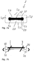
- a second embodiment of a removal tool 89 (FIG. Fig. 18a, 18b ) has similar to a chuck of a mechanical pencil trained elastic tentacles 90 which are slidably mounted in a sleeve 91.
- the tentacles 90 are formed at their free ends with inwardly facing hook-shaped projections. With these hook-shaped projections they are inserted into the mesh of the stent 1.
- the tentacles 90 become pulled so far into the sleeve 91 until the stent 1 is firmly grasped. Then the stent is pulled out of the nose.
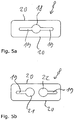
- the rigid insert 25 is completely punched out of the flexible plastic material, as shown in FIG Figure 7a illustrated by two punched lines 29.
- the flexible plastic material thus forms two flexible tongues 30, which are connected to the rigid insert 25 in the connection region 28.
- the flexible tongues 30 thus have openings whose shape is complementary to the end portions of the rigid insert 25.
- Fig. 5b The holding elements according to Fig. 5b .
- Fig. 6 and Fig. 7a and 7b can also be provided in the region of their openings 18, 21, 22, 29 with an integrated funnel.
- the housing 31 also has a first recess 40 and a second recess 41 which have approximately the same shape as the first recess 34 and the second recess 35 of the insert 32 and in the maximum depressed position of the insert 32 with the recesses 34, 35th aligned.
- the recesses 40, 41 thus also have concave arcs 42, which bound the recesses in their longitudinal direction.
- the guide rod is pressed against the action of the spring element 54 in the frame 47, so that the punch plate 52 is lifted by the longitudinal strut 48.
- the two fixing sections 3 of the stents 1 can then be inserted.
- the punch plate 52 is pressed against the longitudinal strut 48, whereby the fixing portions 3 of the stent 1 between the punch plates 52 and the longitudinal struts 48 are clamped.
- the second jaw 56 is L-shaped and has a cuboid cross-section.
- the second clamping jaw 56 comprises a long leg 70 and a short leg formed thereon at a right angle, which is referred to below as a fixing leg 71.
- the long leg 70 is in turn formed groove-shaped with a base wall 72 and two side walls 73.
Landscapes
- Health & Medical Sciences (AREA)
- Public Health (AREA)
- Veterinary Medicine (AREA)
- Animal Behavior & Ethology (AREA)
- General Health & Medical Sciences (AREA)
- Engineering & Computer Science (AREA)
- Biomedical Technology (AREA)
- Heart & Thoracic Surgery (AREA)
- Vascular Medicine (AREA)
- Life Sciences & Earth Sciences (AREA)
- Nursing (AREA)
- Orthopedic Medicine & Surgery (AREA)
- Otolaryngology (AREA)
- Pulmonology (AREA)
- Anesthesiology (AREA)
- Hematology (AREA)
- Media Introduction/Drainage Providing Device (AREA)
- Orthopedics, Nursing, And Contraception (AREA)
- Prostheses (AREA)
Description
Die vorliegende Erfindung betrifft einen Stent zum Schienen eines Nasenganges. Unter dem Handelsnamen "Schnarchzapfen" werden Kunststoffschienen zum Schienen der Nasenöffnungen angeboten. Diese Kunststoffschienen bestehen jeweils aus mehreren Kunststoffringen, die über Längsstreben miteinander verbunden sind. An einem Ende sind zwei derartige Kunststoffschienen mittels eines Kunststoffbügels miteinander verbunden, so dass jeweils zwei Kunststoffschienen in die beiden Löcher einer Nase gesteckt werden können. An dem mit dem Bügel verbundenen Ende ist der Durchmesser der Kunststoffschiene größer als an dem vom Bügel entfernten Ende. Diese Schienen werden somit mit dem schmäleren Ende voran in die Nase gesteckt. Diese Schienen sind etwa 10 mm lang und stellen sicher, dass die Nase im Bereich ihrer Öffnung geöffnet ist.The present invention relates to a stent for splints of a nasal passage. Under the trade name "Schnarchzapfen" plastic rails are offered to rails of the nostrils. These plastic rails each consist of several plastic rings, which are connected to each other via longitudinal struts. At one end, two such plastic rails are connected to each other by means of a plastic strap, so that in each case two plastic rails can be inserted into the two holes of a nose. At the end connected to the bracket, the diameter of the plastic rail is larger than at the end remote from the bracket. These rails are thus stuck with the narrower end ahead in the nose. These rails are about 10 mm long and ensure that the nose is open in the area of its opening.
Unter dem Markenname Nasaline® werden Nasendilatatoren angeboten, die die Nasenflügel erweitern und damit die Mundatmung verringern sollen. Diese Nasendilatatoren sind kurze Kunststoffbuchsen, die über einen Kunststoffbügel lose miteinander verbunden sind, so dass sie in ihrem Abstand verstellbar sind.Under the brand name Nasaline® nasal dilators are offered, which expand the nostrils and thus reduce mouth breathing. These nasal dilators are short plastic sockets that are loosely connected to each other via a plastic strap so that they are adjustable in their spacing.
Diese Produkte "Schnarchzapfen" und Nasaline® sind jeweils buchsen- bzw. rohrförmige Körper, die die Nasenflügel offenhalten sollen.These products, "snore pins" and Nasaline®, are respectively female and tubular bodies designed to keep the nostrils open.
Anstelle von derartigen Buchsenelementen gibt es auch Flügel, mit welchen die Nasenflügel auseinandergedrückt werden. Ein solches Element mit zwei Abstandsflügeln, die über einen steifen Nasenbügel aus Titan in einem vorbestimmten Abstand gehalten werden, ist unter dem Handelsnamen Nasanita Nasenschmetterling® bekannt. Ein auf einem ähnlichen Wirkprinzip beruhendes Element zum Offenhalten der Nasenflügel wird unter dem Handelsnamen Nozovent® vertrieben.Instead of such bushing elements, there are also wings with which the nostrils are pressed apart. Such an element having two spacer wings held at a predetermined distance by a rigid titanium noseband is known by the trade name Nasanita Nose Butterfly®. A nasal wing-open element based on a similar mode of action is sold under the trade name Nozovent®.
Die oben erläuterten Vorrichtungen dienen zum Offenhalten der Nasenöffnungen.The devices explained above serve to keep the nostrils open.
Von der Firma MBM ScienceBridge GmbH, Göttingen, Deutschland wurde eine Nasopharyngeale Schiene entwickelt. Diese Schiene besteht aus zwei Kunststoffschienen, die jeweils muldenförmig geformt sind, wobei die muldenförmigen Schienen an einem Ende mit einem langgestreckten Bügel miteinander verbunden sind. Eine jede Schiene kann in ein Nasenloch eingeführt werden. Die Schienen sind so geformt, dass sie sich durch die Nase, vorbei an der Nasenscheidewand einführen lassen und den oberen Rachen durch seine Form offenhalten. Das Gaumensegel wird daran gehindert, den Rachen zu schließen. Dadurch soll eine kontinuierliche Atmung gewährleistet sein. Bei der Schnarchtherapie werden dem Patienten einmalig per Endoskopie die Schienen angepasst. Dies ist notwendig, um zu gewährleisten, dass die Länge der Schiene exakt eingestellt ist.A nasopharyngeal splint was developed by MBM ScienceBridge GmbH, Göttingen, Germany. This rail consists of two plastic rails, which are each trough-shaped, the trough-shaped rails are connected at one end with an elongated bracket together. Each rail can be inserted into a nostril. The splints are shaped so that they can be inserted through the nose, past the nasal septum, and keep the upper pharynx open by its shape. The soft palate is prevented from closing the throat. This should ensure a continuous breathing. In snoring therapy, the patient is adjusted once by endoscopy the rails. This is necessary to ensure that the length of the rail is precisely set.
Aus der
Aus der
Aus der
Aus der
Die
Aus der
Der vorliegenden Erfindung liegt die Aufgabe zugrunde, einen Stent zum Schienen eines Nasenganges zu schaffen, der nicht an einen jeden Nasengang individuell angepasst werden muss, der einfach einführbar und angenehm zu benutzen ist und einen Nasengang vollständig und zuverlässig offenhält.The present invention has for its object to provide a stent to the rails of a nasal passage, which does not have to be adapted to each nasal passage individually, which is easy to insert and comfortable to use and a nasal passage completely and reliably open.
Die Aufgabe wird durch einen Stent mit dem Merkmal des Anspruchs 1 gelöst. Vorteilhafte Ausgestaltungen sind in den Unteransprüchen angegeben.The object is achieved by a stent with the feature of
Erfindungsgemäß ist ein Stent zum Schienen eines Nasenganges vorgesehen, wobei der Stent aus einem geflochtenen, rohrförmigen Stützkörper ausgebildet ist. Der erfindungsgemäße Stent zeichnet sich dadurch aus, dass der Stützkörper im Wesentlichen zylinderförmig ausgebildet ist und an seinem proximalen Ende einen aufgeweiteten Abschnitt aufweist, der etwa kugelförmig aufgeweitet ist, wobei der Stützkörper im unbelasteten Zustand einen Durchmesser von 4 bis 20 mm und eine Länge von 25 bis 100 mm aufweist.According to the invention, a stent is provided for the rails of a nasal passage, wherein the stent is formed from a braided, tubular support body. The stent according to the invention is characterized in that the support body is substantially cylindrical and has at its proximal end a widened portion which is widened approximately spherically, wherein the support body in the unloaded state has a diameter of 4 to 20 mm and a length of 25 up to 100 mm.
Der erfindungsgemäße Stent zum Schienen eines Nasenganges besteht aus einem geflochtenen, schlauchförmigen Stützkörper und optional einem Fixierabschnitt. Der Stützkörper weist im unbelasteten Zustand einen Durchmesser von mindestens 4 mm und eine Länge im Bereich von 25 mm bis 120 mm und insbesondere von 25 mm bis 100 mm auf.The stent for guiding a nasal passage according to the invention consists of a braided, tubular support body and optionally a fixing section. The support body has a diameter of at least 4 mm and a length in the range of 25 mm to 120 mm and in particular from 25 mm to 100 mm in the unloaded state.
Am proximalen Ende des Stents kann ein Fixierabschnitt angeordnet sein, der zum Fixieren des Stents in einem Nasengang eines Benutzers ausgebildet ist, wobei der Fixierabschnitt sich beim Fixieren aus dem Nasenloch des Benutzers heraus erstreckt und außerhalb der Nase fixierbar ist.At the proximal end of the stent may be arranged a fixing section which is designed to fix the stent in a nasal passage of a user, wherein the fixing section extends out of the nostril of the user during fixation and can be fixed outside the nose.
Der geflochtene Stützkörper ist elastisch verformbar und schmiegt sich an die Innenfläche des Nasenganges an. Der vom rohrförmigen Stützkörper auf den Nasengang erzeugte Druck verteilt sich gleichmäßig, wodurch der Stützkörper in dem empfindlichen Nasengang keine Schmerzen oder unangenehme Gefühle verursacht. Da der Stützkörper geflochten ist, schmiegt er sich an unterschiedliche Formen des Nasenganges an und es ist nicht notwendig, den Stent an den Nasengang eines bestimmten Benutzers individuell anzupassen. Mit einigen wenigen Standardgrößen des Stents, die sich vor allem in der Länge und im Durchmesser des Stützkörpers unterscheiden, kann für fast jede Person ein geeigneter Stent vorgesehen werden. Der Stützkörper kann in Durchmessern von 4 bis 20 mm ausgebildet sein, wobei sich die Standardgrößen vorzugsweise im Durchmesser unterschieden und jeweils 1 mm abgestuft sind. Die Länge des Stützkörpers liegt im Bereich von 25 mm bis 120 mm und insbesondere von 25 mm bis 100 mm. Vorzugsweise sind die Standardgrößen in 5 mm-Stufen in der Länge ausgebildet.The braided support body is elastically deformable and conforms to the inner surface of the nasal passage. The pressure generated by the tubular support body on the nasal passage is distributed evenly, causing the support body in the sensitive nasal passage no pain or unpleasant feelings. Since the support body is braided, it conforms to different forms of the nasal passage and it is not necessary to customize the stent to the nasal passage of a particular user. With a few standard sizes of the stent, which differ mainly in the length and the diameter of the support body, a suitable stent can be provided for almost every person. The support body may be formed in diameters of 4 to 20 mm, wherein the standard sizes preferably differ in diameter and are each graduated 1 mm. The length of the support body is in the range of 25 mm to 120 mm and in particular from 25 mm to 100 mm. Preferably, the standard sizes are formed in 5 mm increments in length.
Die bevorzugte Länge des Stützkörpers liegt im Bereich von 30 mm bis 50 mm, da dies die üblichen Längen der Nasengänge im Bereich der vorderen Nasenmuscheln bei durchschnittlichen Körpergrößen sind.The preferred length of the support body is in the range of 30 mm to 50 mm, as these are the usual lengths of the nasal passages in the area of the anterior nasal turbinates at average body sizes.
Es hat sich gezeigt, dass bei den meisten Nutzern ein Stützkörper mit einer Länge von etwa 60 mm mit seinem distalen Ende an einem Bereich der Nasengänge und Nasenmuscheln liegt, die sehr empfindlich sind. Deshalb ist es meistens zweckmäßig, den Stützkörper entweder kürzer auszubilden, so dass er mit diesem empfindlichen Bereich nicht in Kontakt gelangt, oder länger auszubilden, so dass er sich durch diesen empfindlichen Bereich hindurch erstreckt. Daher sind einerseits Stützkörper mit einer Länge von maximal 40 mm bis etwa 45 bzw. 50 mm oder Stützkörper mit einer Länge von zumindest 70 mm bis 80 mm bzw. 100 mm bevorzugt.It has been found that for most users, a support body about 60 mm in length with its distal end on a region of the nasal passages and nasal turbinates, which are very sensitive. Therefore, it is usually convenient to make the support body either shorter, so that it does not come into contact with this sensitive area, or longer form, so that it extends through this sensitive area. Therefore, on the one hand support body with a maximum length of 40 mm to about 45 or 50 mm or support body with a length of at least 70 mm to 80 mm or 100 mm are preferred.
Die Funktion des Fixierabschnittes liegt darin, dass er verhindert, dass der Stützkörper durch den Nasengang hindurch in Richtung zum Rachen rutschen kann. Der Fixierabschnitt ist deshalb mit dem Stützkörper verbunden und erstreckt sich bis außerhalb der Nase. Hier kann der Fixierabschnitt fixiert werden.The function of the fixing section is that it prevents the support body from slipping through the nasal passage in the direction of the throat. The fixing portion is therefore connected to the support body and extends to outside the nose. Here, the fixing section can be fixed.
Der Fixierabschnitt kann einteilig mit dem Stützkörper als geflochtener, schlauchförmiger, sich zum proximalen Ende hin verjüngender Abschnitt ausgebildet sein. Der Fixierabschnitt kann jedoch auch aus einem beliebigen anderen Material bestehen, das vorzugsweise flexibel ist.The fixing portion may be integrally formed with the support body as a braided, tubular, tapered to the proximal end portion. The fixing section However, it can also be made of any other material that is preferably flexible.
Am proximalen Ende des Fixierabschnittes ist ein Kupplungselement angeordnet, das mit einem Gegenkupplungselement einer Einführstange oder eines Haltelements koppelbar ist. Das Gegenkupplungselement ist an einem Ende der Einführstange angeordnet. Mit der an den Stent gekoppelten Einführstange kann der Stent in einen Einführschlauch eingeführt und komprimiert werden. Hierzu wird die Einführstange durch den Einführschlauch geschoben, so dass der Stent von der Einführstange in den Einführschlauch gezogen wird.At the proximal end of the fixing portion, a coupling element is arranged, which can be coupled with a counter-coupling element of an insertion rod or a holding element. The counter-coupling element is arranged at one end of the insertion rod. With the introducer rod coupled to the stent, the stent can be inserted into an introducer tube and compressed. For this purpose, the insertion rod is pushed through the insertion tube, so that the stent is pulled by the insertion rod into the insertion tube.
Vorzugsweise weist das Halteelement zwei Gegenkupplungselemente zum Koppeln zweier proximaler Enden zweier Stents an das Halteelement auf. Hierdurch bildet das Halteelement einen lösbaren Bügel zwischen den zwei Stents, der sicher verhindert, dass die beiden Stents zu tief in Richtung des Rachens verschoben werden.Preferably, the retaining element has two mating coupling elements for coupling two proximal ends of two stents to the retaining element. As a result, the retaining element forms a releasable stirrup between the two stents, which reliably prevents the two stents from being displaced too deep in the direction of the pharynx.
Das Halteelement kann auch eine Klammer sein, die einen Fixierabschnitt eines Stents oder zwei Fixierabschnitte zweier Stents durch eine Klemmung fixiert. Die Klemmung kann unabhängig vom Kupplungselement zum Koppeln des Stents an eine Einführstange oder aber durch Klemmung des Kupplungselements im Halteelement erfolgen.The holding element may also be a clamp which fixes a fixing section of a stent or two fixing sections of two stents by clamping. The clamping can be done independently of the coupling element for coupling the stent to an insertion rod or by clamping the coupling element in the holding element.
Der Stent kann aus Drähten, Fasern und/oder Fäden, die sich kreuzen, geflochten sein. Im Folgenden wird lediglich der Begriff Draht verwendet, wobei hiermit auch Fasern oder Fäden gemeint sind, sofern der Draht nicht näher definiert ist.The stent may be braided from wires, fibers and / or threads that intersect. In the following, only the term wire is used, whereby also fibers or threads are meant, as long as the wire is not defined further.
Jeder einzelne in Richtung zum distalen Ende des Stents verlaufende Draht wird am distalen Ende des Stützkörpers zurück zum proximalen Ende des Stents geführt. Die hierdurch erzeugten Biegungen werden als runde Enden bezeichnet. Diese weisen im unbelasteten Zustand des Stents einen Durchmesser im Bereich von ca. 0,5 bis 2 mm auf. Auf diese Weise wird ein distales Ende bereitgestellt, an dem keine einzelnen Drahtenden freiliegen oder mit einem weiteren Element miteinander verbunden werden müssen. Die Verbindung des Drahtes bzw. der Drähte des Stents kann am proximalen Ende des Stents z.B. durch Crimpen oder Verkleben erfolgen, so dass ein Fixierabschnitt ausgebildet wird Alternativ können die Drähte auch ohne die Ausbildung eines Fixierabschnitts zusammengefasst werden, z.B. durch einen Kunststofftropfen, einen Ring oder indem sie nach innen zurückgeführt werden in den Stützkörper. Durch die runden Enden werden Verletzungen der Atemwege durch das distale Ende des Stents vermieden.Each individual wire extending in the direction of the distal end of the stent is guided at the distal end of the support body back to the proximal end of the stent. The bends created thereby are referred to as round ends. These have a diameter in the range of about 0.5 to 2 mm in the unloaded state of the stent. In this way, a distal end is provided on which no individual wire ends need to be exposed or connected to another element. The connection of the wire (s) of the stent may be at the proximal end of the stent e.g. by crimping or gluing, so that a fixing section is formed. Alternatively, the wires can be combined without the formation of a fixing section, e.g. by a plastic drop, a ring or by being returned to the inside of the support body. The round ends prevent airway injuries through the distal end of the stent.
Der Draht, aus dem der Stützkörper geflochten ist, ist insbesondere ein Metalldraht, vorzugsweise ein Nitinoldraht oder ein Stahldraht.The wire from which the support body is braided is in particular a metal wire, preferably a nitinol wire or a steel wire.
Vorzugsweise ist das distale Ende des Stützkörpers, am meisten bevorzugt nur die runden Enden, gegenüber dem übrigen Bereich des Stützkörpers etwas verjüngt ausgebildet. Hierdurch wird verhindert, dass sich der Stent mit seiner Endkante in den Nasengang eindrückt. Dies kann unangenehm sein.Preferably, the distal end of the support body, most preferably only the round ends, formed slightly tapered with respect to the remaining region of the support body. This prevents the stent from pressing into the nasal passage with its end edge. This can be uncomfortable.
Der Stützkörper kann an seinem proximalen Ende einen aufgeweiteten Abschnitt aufweisen. Dieser aufgeweitete Abschnitt ist vorzugsweise etwa kugelförmig aufgeweitet. Die Kugel weist einen Durchmesser von etwa 10 bis 20 mm, vorzugsweise 12 bzw. 13 bis 15 bzw. 17 mm auf. Dieser aufgeweitete Abschnitt des Stützkörpers wird bei Gebrauch im Bereich unmittelbar hinter den Nasenöffnungen angeordnet, um die Nasenflügel gegen einen Kollaps abzustützen. Zusätzlich fixiert der aufgeweitete Abschnitt den Stent in der Nase, so dass insbesondere bei einem Stent mit aufgeweitetem Abschnitt der oben erläuterte Fixierabschnitt entfallen kann. Ein solcher Stent ist besonders für sportliche Tätigkeiten geeignet, bei welchen die Nasengänge offen gehalten werden sollen. Ein an der Nase vorstehender Fixierabschnitt ist bei solchen sportlichen Tätigkeiten nicht erwünscht.The support body may have a flared portion at its proximal end. This flared portion is preferably widened approximately spherically. The ball has a diameter of about 10 to 20 mm, preferably 12 or 13 to 15 or 17 mm. This expanded portion of the support body is placed in use immediately in the area behind the nostrils to support the nostrils against collapse. In addition, the flared portion fixes the stent in the nose, so that can be omitted in particular in a stent with flared portion of the above-described fixing. Such a stent is particularly suitable for sports activities in which the nasal passages are to be kept open. A protruding on the nose Fixierabschnitt is not desirable in such sports activities.
Bei einem Stent ohne Fixierabschnitt ist es zweckmäßig ein Entfernungswerkzeug vorzusehen, mit dem der Stent aus einem Nasengang entfernt werden kann. Das Entfernungswerkzeug ist an den Stent koppelbar, bspw, indem es ein Element zum Einhaken in das Geflecht des Stents oder ein Element zum Greifen des Geflechts aufweist. Zum Koppeln an das Entfernungswerkzeug genügt alleine der geflochtene Stützkörper. Hierzu muss am Stent kein weiterer Bestandteil vorgesehen werden.In the case of a stent without a fixation section, it is expedient to provide a removal tool with which the stent can be removed from a nasal passage. The removal tool is couplable to the stent, for example by having an element for hooking into the braid of the stent or a member for gripping the braid. For coupling to the removal tool, the braided support body alone is sufficient. For this purpose, no other component must be provided on the stent.
Die Erfindung wird nachfolgend beispielhaft anhand der Zeichnungen näher erläutert. Die Zeichnungen zeigen in:
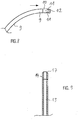
- Fig. 1
- einen nicht-erfindungsgemäßen Stent nach einem Ausführungsbeispiel schematisch in einer Seitenansicht,
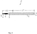
- Fig. 2
- einen nicht-erfindungsgemäßen Stent nach einem weiteren Ausführungsbeispiel schematisch in einer Seitenansicht,
- Fig. 3
- einen erfindungsgemäßen Stent schematisch in einer Seitenansicht,
- Fig. 4
- einen nicht-erfindungsgemäßen Stent nach einem weiteren Ausführungsbeispiel schematisch in einer Seitenansicht,
- Fig. 5a, 5a
- jeweils ein Haltelement in der Draufsicht,
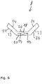
- Fig. 6
- ein weiteres Haltelement in der Draufsicht,
- Fig. 7a, 7b
- ein Halteelement in der Draufsicht und in einer Seitenansicht,
- Fig. 8
- einen Abschnitt einer Einführstange in einer Seitenansicht,
- Fig. 9
- einen Abschnitt eines Einführschlauches in einer Schnittansicht,
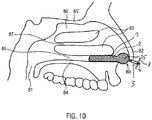
- Fig. 10
- schematisch die Nasenhöhle in einer Schnittdarstellung,
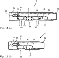
- Fig. 11a und 11b
- schematisch grob vereinfacht ein weiteres Halteelement in der Seitenansicht,
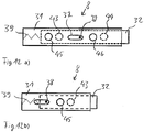
- Fig. 12a und 12b
- schematisch grob vereinfacht ein weiteres Halteelement in der Seitenansicht,
- Fig. 13a und 13b
- schematisch grob vereinfacht ein weiteres Halteelement in der Seitenansicht,
- Fig. 14a bis 14c
- schematisch grob vereinfacht ein weiteres Halteelement in der Seitenansicht,
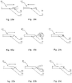
- Fig. 15a, b bis 17a, b
- jeweils einen proximalen Endbereich eines Stents ohne Fixierabschnitt in einer Vorderansicht (Fig. a) und in einer Seitenansicht (Fig. b), und
- Fig. 18a, 18b, 19a, 19b, 19c, 20a, 20b, 20c
- jeweils ein Entfernungswerkzeug zum Entfernen eines Stents au seiner Nase in unterschiedlichen Greifzuständen.
- Fig. 1
- a non-inventive stent according to an embodiment schematically in a side view,
- Fig. 2
- a non-inventive stent according to a further embodiment schematically in a side view,
- Fig. 3
- a stent according to the invention schematically in a side view,
- Fig. 4
- a non-inventive stent according to a further embodiment schematically in a side view,
- Fig. 5a, 5a
- each a holding element in plan view,
- Fig. 6
- another holding element in the plan view,
- Fig. 7a, 7b
- a holding element in plan view and in a side view,
- Fig. 8
- a section of an insertion rod in a side view,
- Fig. 9
- a section of an insertion tube in a sectional view,
- Fig. 10
- schematically the nasal cavity in a sectional view,
- Fig. 11a and 11b
- schematically roughly simplified another holding element in the side view,
- Fig. 12a and 12b
- schematically roughly simplified another holding element in the side view,
- Fig. 13a and 13b
- schematically roughly simplified another holding element in the side view,
- Fig. 14a to 14c
- schematically roughly simplified another holding element in the side view,
- Fig. 15a, b to 17a, b
- each a proximal end portion of a stent without fixing portion in a front view (Fig. A) and in a side view (Fig. B), and
- 18a, 18b, 19a, 19b, 19c, 20a, 20b, 20c
- each a removal tool for removing a stent on his nose in different gripping conditions.
Ein erfindungsgemäßer Stent 1 zum Schienen eines Nasenganges umfasst einen Stützkörper 2 und einen Fixierabschnitt 3.An
Der Stent 1 kann aus einem einzigen Draht oder aus einer Vielzahl von Drähten geflochten sein. Die Enden des Drahtes bzw. der Drähte sind am proximalen Ende des Stents bzw. am proximalen Ende des Fixierabschnitts 3 mit einem stiftförmigen bzw. zylinderförmigen Körper 5 zusammengefasst. Im vorliegenden Ausführungsbeispiel ist der stiftförmige Körper 5 ein um die Enden der Drähte gecrimpter Körper 5. Man kann ihn deshalb auch als Crimpkörper 5 bezeichnen. Am distalen Ende des Crimpkörpers 5 ist ein dünner Stift 6 angeformt. Am vom Crimpkörper 5 entfernten Ende des Stiftes 6 ist eine Kugelkupplung 7 ausgebildet. Mit der Kugelkupplung 7 kann der Stent an ein anderes Element gekoppelt werden, das ein entsprechendes Gegenkupplungselement aufweist.The
Der Stent ist aus einem elastischen Draht mit einem Durchmesser von 0,001 mm bis 2 mm, insbesondere mit einem Durchmesser von 0,05 mm bis 0,5 mm und vorzugsweise mit einem Durchmesser von 0,07 mm bis 0,2 mm geflochten. Der Draht ist insbesondere ein Metalldraht und vorzugsweise ein Nitinoldraht oder Stahldraht.The stent is braided from an elastic wire with a diameter of 0.001 mm to 2 mm, in particular with a diameter of 0.05 mm to 0.5 mm and preferably with a diameter of 0.07 mm to 0.2 mm. The wire is in particular a metal wire and preferably a nitinol wire or steel wire.
Die Länge L2 des Stützkörpers 2 beträgt 25 mm bis 120 mm und insbesondere 25 mm bis 100 mm. Vorzugsweise liegt die Länge L2 des Stützkörpers im Bereich von 30 mm bis 50 mm oder von 60 mm bis 120 mm bzw. von 30 mm bis 50 mm oder von 70 mm bis 100 mm. Bei der längeren Ausführung ist am meisten bevorzugt ein Bereich von 70 bis 100 mm.The length L2 of the
Der Durchmesser des Stützkörpers 2 liegt im Bereich von 4 mm bis 20 mm. Vorzugsweise weist der Stützkörper einen Durchmesser von zumindest 5 mm und insbesondere von zumindest 6 mm auf.The diameter of the
Der Fixierabschnitt 3 weist eine Länge L2 von etwa 10 bis 25 mm auf. Mit dem Fixierabschnitt kann der Stent derart am Körper des Benutzers fixiert werden, dass der Stent nicht aus dem Nasengang des Benutzers in Richtung zum Rachen verschoben werden kann. Hierzu ist es notwendig, dass der Fixierabschnitt sich durch die Nasenöffnung nach außen erstreckt, um dann dort mit einem entsprechenden Fixierelement fixiert zu werden. Ein solches Fixierelement kann beispielsweise ein Pflaster sein, mit dem der Fixierabschnitt 3 im Bereich unterhalb der Nase des Benutzers festgeklebt wird. Bevorzugt wird jedoch ein Haltelement 8, das sich zumindest in eine Richtung soweit erstreckt, dass es nicht durch eine Nasenöffnung in den Nasengang eingeführt werden kann. Alternativ kann das Halteelement 8 so ausgebildet sein, dass es mit zwei Stents 1 koppelbar ist, so dass es sich wie ein Bügel zwischen beiden Stents erstreckt und so ein zu tiefes Einziehen des Stents in den Nasengang verhindert. Ein solches Halteelement 8, das unten näher erläutert wird, wird vorzugsweise an das Kupplungselement des Stents, das im vorliegenden Ausführungsbeispiel als Kugelkupplung 7 ausgebildet ist, gekoppelt. Im Rahmen der Erfindung ist es jedoch auch möglich, als Haltelement eine Klemme vorzusehen, die an den Fixierabschnitt 3 eines Stents 1 oder an die Fixierabschnitte 3 zweier Stents 1 geklemmt wird.The fixing
Eine Einführstange 9, die an das Kupplungselement 7 gekoppelt werden kann, ist in
Die Einführstange kann auch als Einführrohr (nicht dargestellt) ausgebildet werden, in das an einem Ende die beiden kreisförmigen Durchgangsöffnungen und optional ein Schlitz - ähnlich wie bei der Buchse 10 - eingearbeitet sind. Dadurch entfällt die separate Herstellung der rohrförmigen Buchse.The insertion rod can also be formed as an insertion tube (not shown) into which at one end the two circular passage openings and optionally a slot - similar to the socket 10 - are incorporated. This eliminates the separate production of the tubular socket.
Der Durchmesser der Einführstange 9 und des Crimpkörpers 5 sind so bemessen, dass die Einführstange 9 zusammen mit dem Stent 1 in einen Einführschlauch 13 eingeführt werden können (
Der Einführschlauch kann auch mehrschichtig ausgebildet sein, wobei die innere Schicht vorzugsweise härter als die äußere Schicht ist, um innen eine glatte Oberfläche mit geringer Reibung bereitzustellen (z.B. PEBAX 7233). Hierdurch kann der Stent mit geringem Widerstand in den Einführschlauch eingeführt und wieder herausgezogen werden. Die äussere Schicht hat vorzugsweise eine Shorehärte von z.B. 60A bis 95A und ist dicker als die innenliegende Schicht, damit der Einführschlauch insgesamt in seinen Materialeigenschaften weich und flexibel ist und sich dadurch gut an den Verlauf des Nasengangs anpasst. Auf diese Weise ist der Schlauch leicht einführbar. Vorzugsweise wird die äussere Schicht aus PU 85A mit einer Schichtdicke von ca. 0,2 mm ausgeführt und die innenliegende aus PEBAX 7233 mit einer Schichtdicke von ca. 0,1 mm. Durch Anschmelzen einer kurzen Spitze aus PU 85A (ca. 2 bis 10 mm lang), die vorzugsweise atraumatisch verrundet ist, werden Komfort und Sicherheit bei der Einführung des Schlauches durch den Nasengang noch weiter gesteigert. Der Einführschlauch 13 kann geradlinig geformt sein. Er kann jedoch auch eine Krümmung aufweisen.The insertion tube may also be formed in a multi-layered manner, wherein the inner layer is preferably harder than the outer layer in order to have a smooth surface on the inside Provide friction (eg PEBAX 7233). As a result, the stent can be inserted with little resistance into the insertion tube and pulled out again. The outer layer preferably has a Shore hardness of, for example, 60A to 95A, and is thicker than the inner layer, so that the insertion tube as a whole is soft and flexible in its material properties and thus adapts well to the course of the nasal passage. In this way, the tube is easy to insert. Preferably, the outer layer is made of PU 85A with a layer thickness of about 0.2 mm and the inner layer of PEBAX 7233 with a layer thickness of about 0.1 mm. By melting a short tip of PU 85A (about 2 to 10 mm long), which is preferably atraumatisch rounded, comfort and safety in the introduction of the tube through the nasal passage are further increased. The
Der Außendurchmesser des Einführschlauchs beträgt bis zu 10 mm, bevorzugt bis zu 5 mm, um dem Benutzer eine komfortable, schmerzfreie Einführung des Stents zu ermöglichen. Der Innendurchmesser des Einführschlauchs beträgt bis zu 4 mm, um ausreichend Raum zur Aufnahme des Stents 1 bereitzustellen.The outer diameter of the introducer tube is up to 10 mm, preferably up to 5 mm, to allow the user a comfortable, painless insertion of the stent. The inner diameter of the insertion tube is up to 4 mm to provide sufficient space for receiving the
Die Einführspitze weist am außenseitigen Randbereich eine Fase 17 auf. Anstelle der Fase 17 kann die Einführspitze 14 auch mit einer Rundung ausgebildet sein. Eine solche Rundung kann beispielsweise mittels einer thermischen Umformung oder mittels Schleifen oder Laserabtragen erzeugt werden. Eine solche Rundung kann außenseitig und/oder innenseitig ausgebildet sein.The insertion tip has a
Eine solche abgerundete Spitze ist in der Herstellung aufwändiger als eine Fase. Die abgerundete Spitze ist jedoch noch sicherer beim Einführen des Stents. Zudem kann bei einer Fase das sich ergebende dünnwandige Ende verhärten, indem die Weichmacher aus dem Kunststoffmaterial durch die relativ große Oberfläche entweichen.Such a rounded tip is more complex to produce than a chamfer. However, the rounded tip is even safer when inserting the stent. In addition, in a chamfer, the resulting thin-walled end can harden by the plasticizers escape from the plastic material through the relatively large surface.
Der Einführschlauch kann auch eine oliven- oder tropfenförmige Verdickung an einem Ende oder beiden Enden aufweisen, um das Einführen in den Nasengang zu erleichtern. Die Olive oder der Tropfen am Ende des Einführschlauchs hat eine Länge von 2-20 mm, vorzugsweise 2-10 mm und noch mehr bevorzugt 2-5 mm. Der Durchmesser der Olive oder des Tropfens ist etwa 3,5-6,0 mm, bevorzugt 4,0-5,0 mm.The introducer tube may also have an olive or teardrop-shaped thickening at one end or both ends to facilitate insertion into the nasal passageway. The olive or the drop at the end of the insertion tube has a length of 2-20 mm, preferably 2-10 mm and more preferably 2-5 mm. The diameter of the olive or the drop is about 3.5-6.0 mm, preferably 4.0-5.0 mm.
Diese geformten Einführspitzen 14 stellen atraumatische Spitzen dar, wobei die Form umso glatter und runder sein sollte, je härter das Material der Spitze ist. Eine oliven- oder tropfenförmige Ausführung weist die größte Stirnfläche auf und somit die beste Druckverteilung auf das Nasengewebe.These shaped
Zum Einführen des Stents 1 in den Einführschlauch 13 wird der Stent 1 zunächst mittels der Kugelkupplung 7 an der Buchse 10 der Einführstange 9 fixiert. Die Einführstange wird dann mit ihrem proximalen Ende an der Einführspitze 14 des Einführschlauches 13 in diesen eingeführt. Die Einführstange 9 wird durch den Einführschlauch 13 hindurchgeschoben bis der Stent 1 vollständig im Einführschlauch 13 aufgenommen ist. Hierbei kann der Stent 1 auch geringfügig am Einführschlauch etwas vorstehen. Wesentlich ist, dass der Stent 1 durch das Einführen in den Einführschlauch 13 auf einen geringen Durchmesser komprimiert ist, so dass er zusammen mit dem Einführschlauch und der Einführstange einfach in den Nasengang eingeführt werden kann. Alternativ wird der Stent 1 ohne ein Kupplungselement 7 in den Einführschlauch 13 hineingeschoben, wobei keine lösbare Verbindung mit einer Einführstange hergestellt wird. Ausführungsformen ohne Kupplungselement werden unten noch näher erläutert.For insertion of the
Ist diese Anordnung aus Stent 1, Einführschlauch 13 und Einführstange 9 so weit eingeführt, dass sich der Stützkörper 2 im Nasengang befindet, wird zunächst der Einführschlauch 13 über die Einführstange 9 hinweg abgezogen und dann die Einführstange vom Stent 1 gelöst. Die glatte Oberfläche des Einführschlauches 13 erleichtert erheblich das Einführen des Stents 1 in den Nasengang.If this arrangement of
Dieser kugelförmig aufgeweitete Abschnitt 15 ist vorgesehen, um im Bereich unmittelbar hinter der Nasenöffnung angeordnet zu werden, damit die Nasenflügel gegen einen Kollaps abgestützt werden.This spherically flared
Insbesondere bei der Ausführungsform mit aufgeweitetetem Abschnittt kann ein Verzicht auf einen Fixierabschnitt vorteilhaft sein, weil durch den kugelförmig aufgeweiteten Abschnitt 15 bereits eine ausreichende Fixierung in der Nase erfolgen kann, so dass ein Haltelement nicht unbedingt notwendig ist.In particular, in the embodiment with widenedetem section, a waiver of a fixing can be advantageous because the spherical widened
Nachfolgend werden einige Ausführungsformen des Stents ohne Fixierabschnitt bzw. ohne Kupplungselement anhand der
Bei der Ausführungsform gemäß
Bei einer weiteren Ausführungsform (
Gemäß einer weiteren Ausführungsform (
Bei einem Stent ohne Kupplungselement wird der Einführschlauch über eine Einführstange, die keine rohrförmige Buchse enthält, oder über ein Einführrohr, das keine Durchgangsöffnungen und keinen Schlitz enthält, hinweg abgezogen, wobei sich der Stent im Nasengang entfaltet und positioniert.In a stent without a coupling element, the introducer tube is withdrawn via an introducer rod that does not contain a tubular socket, or via an introducer tube that does not include through-holes and a slot, whereby the stent unfolds and positions in the nasal passageway.
In
Ist der Stent ohne Kupplungselement, wie z.B. einer Kugelkupplung, ausgebildet, dann ist es zweckmäßig, ein Entfernungswerkzeug einzusetzen, um den Stent 1 wieder aus der Nase herauszuziehen. Die einfachste Ausführungsform ist ein dünner gestreckter Körper aus Kunststoff oder Metall, der am distalen Ende eine hakenförmige Krümmung aufweist (nicht dargestellt). Diese Krümmung wird in das Drahtgeflecht des Stents 1 eingeführt und der Stent mittels des Entfernungswerkzeugs aus der Nase herausgezogen
Alternativ können verschiedene andere Ausführungsformen von Entfernungswerkzeugen 89 eingesetzt werden, wie sie im Folgenden anhand der
Alternatively, various other embodiments of
Eine zweite Ausführungsform eines Entfernungswerkzeug 89 (
In den
Eine vierte Ausführungsform eines Entfernungswerkzeug 89 (
Eine Kugelkupplung 7 eines Stents 1 kann durch die Öffnung 18 des Halteelements 8 hindurchgeführt werden und der Stent kann in einen der beiden Schlitze 19 verschoben werden, wobei der Stent 1 sich mit seinem Stift 6 oder mit dem Drahtgeflecht durch den jeweiligen Schlitz 19 hindurch erstreckt. Ein zweiter Stent kann mit seiner Kugelkupplung 7 in die Öffnung 18 eingeführt und in den anderen Schlitz 19 verschoben werden. Die Stents 1 werden in das Halteelement 8 eingehängt, wenn sie bereits in den Nasengang eingeführt und der Einführschlauch sowie die Einführhilfe entfernt sind. Durch die Anordnung der Stents 1 in der Nase sind sie voneinander beabstandet, so dass zuverlässig verhindert wird, dass die Kugelkupplungen 7 in Richtung zur Öffnung 18 rutschen. Somit ist das Halteelement mit beiden Stents 1 verliersicher verbunden. Das Halteelement 8 bildet somit zwischen den beiden Stents 1 einen Bügel, der verhindert, dass die Stents zu tief in den Nasengang und insbesondere in den Rachen eindringen können.A ball coupling 7 of a
Es ist vor allem auch zweckmäßig die Öffnung 18 mit einem am Halteelement 8 integrierten Trichter (nicht dargestellt) zu versehen, der das Einführen der Kugelkupplung 7 erleichtert. Beim Einführen der Kugelkupplung 7 in die Öffnung 18 ist der Stent 1 mit seinem Stützkörper im Nasengang angeordnet. Die Kugelkupplung 7 befindet sich somit unmittelbar vor der Nase und am Rande des Sichtfeldes des Benutzers. Daher ist ein derartiger Trichter sehr vorteilhaft, denn damit ist es möglich, das Halteelement an den Stent 1 zu koppeln, ohne dass man das Halteelement und den Fixierabschnitt 3 des Stents 1 sieht.Above all, it is also expedient to provide the
Ein drittes Ausführungsbeispiel des Halteelementes 8 ist in
Die Längskanten 24 der Stützflügel 23 begrenzen mit den Längskanten 20 des Hauptkörpers des Halteelements 8 einen Winkel im Bereich von 120° bis 150°.The longitudinal edges 24 of the
Wie es in
Dieses Halteelement 8 gemäß
Die Halteelemente gemäß
Das Gehäuse 31 weist zwei diametral gegenüberliegende Längsschlitze 37 auf, in welchen jeweils ein Ende eines mit dem Einsatz 32 verbundener Querstift 38 gelagert ist. Durch den Querstift 38 ist die Bewegung des Einsatzes 32 im Gehäuse 31 begrenzt, wobei bei einer maximal eingedrückten Stellung des Einsatzes 32 der Querstift 38 am zur Stirnwandung 33 weisenden Ende des Längsschlitzes 37 anschlägt und bei einer maximal ausgefahrenen Stellung des Einsatzes 32 der Querstift 38 an dem von der Stirnwandung 33 entfernten Ende des Längsschlitzes 37 anschlägt. Die Länge des Längsschlitzes 37 entspricht somit dem maximalen Weg des Einsatzes 32 im Gehäuse 31. Zwischen der Stirnwandung 33 und dem Einsatz 32 befindet sich ein Federelement 39, das den Einsatz 32 in seine maximal ausgefahrene Stellung drückt (
Das Gehäuse 31 weist auch eine erste Ausnehmung 40 und eine zweite Ausnehmung 41 auf, die etwa die gleiche Form wie die erste Ausnehmung 34 und die zweite Ausnehmung 35 des Einsatzes 32 aufweisen und in der maximal eingedrückten Stellung des Einsatzes 32 mit den Ausnehmungen 34, 35 fluchten. Die Ausnehmungen 40, 41 weisen somit auch konkave Bögen 42 auf, die die Ausnehmungen in ihrer Längsrichtung begrenzen.The
In einer eingedrückten Stellung des Einsatzes 32, in der die ersten Ausnehmungen 34, 40 und die zweiten Ausnehmungen 35, 41 etwa fluchten, ergibt sich somit eine durchgehende Ausnehmung, in welche jeweils ein Fixierabschnitt 3 eines Stents 1 eingefügt werden kann. Wird dann der Einsatz 32 freigegeben, so wird er durch das Federelement 39 von der Stirnwandung 33 weggedrückt, wodurch die konkaven Bögen 36 der Ausnehmungen des Einsatzes und die konkaven Bögen 42 des Gehäuses 31 aufeinander zu bewegt werden und zwischen sich die Fixierabschnitte 3 der Stents 1 einklemmen.In a depressed position of the
Der Einsatz 32 wird an seinem am offenen Ende des Gehäuses 31 vorstehenden Abschnitt betätigt, um gegen das Federelement 39 gedrückt zu werden.The
In
Zum Verbinden dieses Haltelementes 8 mit den Fixierabschnitten 3 zweiter Stents 1 wird die Führungsstange gegen die Wirkung des Federelementes 54 in den Rahmen 47 eingedrückt, so dass die Stempelplatte 52 von der Längsstrebe 48 angehoben wird. In dem Bereich zwischen der Stempelplatte 52 und der Längsstrebe 48 können dann die beiden Fixierabschnitte 3 der Stents 1 eingeführt werden. Durch Freigeben der Führungsstange 53 wird die Stempelplatte 52 gegen die Längsstrebe 48 gedrückt, wodurch die Fixierabschnitte 3 des Stents 1 zwischen den Stempelplatten 52 und den Längsstreben 48 eingeklemmt werden.To connect this holding
Der Vorteil dieses Halteelementes 8 liegt darin, dass der geöffnete Bereich zwischen der Stempelplatte 52 und den Längsstreben 48 sehr groß ist, so dass es einfach ist, die Fixierabschnitte 3 einzuführen.The advantage of this holding
In der
Die erste Klemmbacke 55 wird im Folgenden als Basisbacke bezeichnet. Die Basisbacke 55 weist eine Basiswandung 58 auf. Die Basiswandung umfasst eine Oberseite 59, eine Unterseite 60 und von der Basiswandung 58 erstrecken sich an deren Längsseiten zwei Seitenwandungen 61 nach oben, so dass die Basiswandung 58 und die zwei Seitenwandungen 61 eine U-förmige Ausnehmung 62 begrenzen. Die beiden gegenüberliegenden Enden der quaderförmigen Basiswandung 58 werden als Gelenkseite 63 und Verschlussseite 64 bezeichnet.The
An der Gelenkseite 63 der Basiswandung 58 sind zwei Ringscheibenelemente 65 beabstandet voneinander angeformt, die bündig zu den Außenflächen der Seitenwandungen 61 ausgebildet sind. Die Ringscheibenelemente 65 weisen jeweils eine kreisförmige Durchgangsöffnung 66 auf, die zueinander fluchten. Die Durchgangsöffnungen 66 sind jeweils zur Aufnahme einer Rohrwelle 67 ausgebildet. Die Rohrwelle 67 ist drehbar in den Durchgangsöffnungen 66 angeordnet und bündig zu den Außenflächen der Seitenwandungen 61 ausgebildet. Über die Rohrwelle 67 ist die erste Klemmbacke 55 gelenkig mit der zweiten Klemmbacke 56 verbunden.At the
An der Verschlussseite 64 erstrecken sich die Seitenwandungen 61 über den stirnseitigen Rand der Basiswandung 58 hinaus, so dass sie in der Draufsicht auf die Basisbacke 55 die U-förmige Ausnehmung begrenzen. Die Seitenwandungen sind in diesem Bereich ein Stück nach oben gezogen.On the
Die stirnseitige Kante der Basiswandung 58 an der Unterseite 60 wird im Folgenden als Fixierkante 68 bezeichnet.The end edge of the
In der U-förmigen Ausnehmung bzw. Nut 62 ist ein quaderförmiger Fixierblock 69 angeordnet. Der quaderförmige Fixierblock 69 ragt in etwa 3 mm auf der Oberseite 59 der Basiswandung 58 heraus. Der quaderförmige Fixierblock 69 ist aus einem Kunststoff, insbesondere Silikon, ausgebildet und bildet ein Fixierelement aus.In the U-shaped recess or
Die zweite Klemmbacke 56 ist L-förmig ausgebildet und weist einen quaderförmigen Querschnitt auf. Die zweite Klemmbacke 56 umfasst einen langen Schenkel 70 und einen daran im rechten Winkel angeformten kurzen Schenkel, der im Folgenden als Fixierschenkel 71 bezeichnet wird. Der lange Schenkel 70 ist wiederum nutförmig mit einer Basiswandung 72 und zwei Seitenwandungen 73 ausgebildet.The
Das dem Fixierschenkel 71 gegenüberliegende Ende des langen Schenkels 70 wird als Gelenkseite 74 bezeichnet. An diese Gelenkseite 74 ist ein rohrförmiger Gelenkkörper 75 angeformt. Der Gelenkkörper 75 bildet ein Rohr mit zwei Stirnseiten und einem kreisförmigen Durchgang, wobei die Länge des Rohrs der lichten Weite zwischen den beiden Ringscheibenelementen 65 entspricht. In der Durchgangsöffnung des Gelenkkörpers ist die Rohrwelle 67 angeordnet. Die Rohrwelle 67 lagert drehbar in den Durchgangsöffnungen 66 der Ringscheibenelemente 65 und in der Durchgangsöffnung des Gelenkkörpers 75.The fixing
Im Fixierschenkel 71 ist ein Durchgangsloch ausgebildet (nicht dargestellt), das mit der Nut des langen Schenkels 70 fluchtet. Im rohrförmigen Gelenkkörper 75 ist eine Ausnehmung eingebracht, die auch mit der Nut des langen Schenkels 70 fluchtet. Im Durchgangsloch, der Nut des langen Schenkels 70 und der Ausnehmung des Gelenkkörpers 75 ist ein Fixierschlauch 77 aufgenommen. Der Fixierschlauch 77 bzw. das Fixierelement ist aus Kunststoff, insbesondere Silikon, ausgebildet.In the fixing
Am freien Ende des Fixierschenkels 71 ist eine in Richtung zum Gelenkkörper 75 zeigende Rastnase 78 ausgebildet. Die Rastnase 78 ist derart ausgebildet, dass sie die Fixierkante 71 hintergreift, wenn die beiden Schenkel zusammengedrückt werden. Die Rastnase 78 rastet dann hinter der Fixierkante 68 ein und hält das Halteelement 8 in einem geschlossenen Zustand. Die Rastnase 78 und die Fixierkante bilden so ein Verschlusselement aus. Im geschlossenen Zustand des Halteelementes sind die Basisbacke 55 und die zweite Klemmbacke 56 etwa parallel zueinander angeordnet, wobei der Fixierblock 69 und der Fixierschlauch 77 aufeinandergepresst werden.At the free end of the fixing
Zwischen dem Fixierblock 69 der Basisbacke 55 und dem Fixierschlauch 77 der zweiten Klemmbacke 56 kann ein Fixierabschnitt 3 eines Stents 1 angeordnet werden. Es ist auch möglich, mit diesem Halteelement gleichzeitig zwei Fixierabschnitte 3 zweier Stents gleichzeitig zwischen einem Fixierblock 69 und einem Fixierschlauch 77 zu fixieren. Dazu ist es zweckmäßig, dass sich der Fixierblock 69 und der Fixierschlauch 77 jeweils über eine Länge von zumindest 2 bis 3 cm erstrecken.A fixing
Im Rahmen der Erfindung kann es auch zweckmäßig sein, ein derartiges Halteelement in miniaturisierter Ausführungsform auszubilden, wobei sich die Klemmbacken 55, 56 beispielsweise lediglich über eine Länge von etwa 1 cm erstrecken. Zwei derartige Halteelemente sind dann mit einem biegsamen Band miteinander verbunden, so dass mit jeweils einem der Halteelemente ein Stent fixiert werden kann.In the context of the invention, it may also be expedient to form such a holding element in a miniaturized embodiment, wherein the clamping
Die oben erläuterten Halteelemente 8 sind jeweils zum Sichern zweier Stents 1 ausgebildet. Im Rahmen der Erfindung ist es selbstverständlich auch möglich, ein Halteelement 8 zum Fixieren lediglich eines einzigen Stents auszubilden. Hierbei ist es zweckmäßig, wenn sich das Halteelement zumindest in eine Richtung soweit erstreckt, dass das Halteelement nicht durch ein Nasenloch hineingezogen werden kann.The above-described
Sind die Nasenmuscheln angeschwollen, dann kann ein Nasengang mit dem erfindungsgemäßen Stent offengehalten werden. Der Stent 1 wird vor allem im unteren Nasengang 86 eingesetzt. Es ist jedoch auch möglich, ihn im mittleren Nasengang 87 bzw. oberen Nasengang 88 einzusetzen. Vor allem der untere Nasengang 86 weist in seinem hinteren Bereich eine besondere Empfindlichkeit auf. In diesem Bereich sollte der Stützkörper 2 des Stents 1 möglichst nicht enden, da die rückwärtige Kante unangenehm auf die Nasenmuschel 83 drücken könnte. Es ist deshalb zweckmäßig, den Stützkörper so anzuordnen, dass er nur den vorderen Bereich des Nasengangs schient oder sich vollständig durch den Nasengang hindurch erstreckt.If the turbinates swelled, then a nasal passage can be kept open with the stent according to the invention. The
Es ist auch vorteilhaft, dass der erfindungsgemäße Stent biegsam ist, so dass er sich an die Konturen der Nasengänge anschmiegen kann. Dies wird einerseits durch die Elastizität des Drahtes und andererseits durch die Ausbildung als Geflecht bewerkstelligt.It is also advantageous that the stent according to the invention is flexible, so that it can conform to the contours of the nasal passages. This is done on the one hand by the elasticity of the wire and on the other hand by the formation of a braid.
Im Rahmen der Erfindung ist es möglich, lediglich einen einzigen Stent zu verwenden. In der Regel werden jedoch zwei Stents 1 eingesetzt. Die beiden Stents sind normalerweise gleich ausgebildet. In speziellen Anwendungen kann es jedoch auch sinnvoll sein, zwei Stents unterschiedlicher Größe (unterschiedlicher Länge und/oder mit unterschiedlichem Durchmesser und/oder unterschiedlicher Bauart) zu verwenden. So kann es auch manchmal sinnvoll sein, einen erfindungsgemäßen Stent zum Schienen eines Nasenganges mit einem Stent zum Schienen des Atemweges im Rachenraum, wie er z.B. aus der
Claims (12)
- A stent for splinting a nasal passage, the stent (1) being designed of a braided, tubular support body (2),
characterized in that
the support body (2) is substantially cylindrical and has a widened area (15) at the proximal end thereof, said widened area being widened approximately spherically, wherein, in an unloaded state, the support body has a diameter of 4 to 20 mm and a length of 25 to 100 mm. - The stent according to claim 1,
characterized in that
the widened area (15) has a diameter of at least 10 mm, in particular 10-20 mm. - The stent according to claim 1 or 2,
characterized in that
the stent (1) has a fixing section (3), which is arranged at the proximal end of the stent (1) and is designed to fix the stent (1) in a nasal passage of a user, wherein during fixing the fixing section (3) protrudes from the nostril of the user and can be fixed outside the nose. - The stent according to any of claims 1 to 3,
characterized in that
the stent is compressible in an insertion tube (14) and is self-expanding when it is released from the insertion tube. - The stent according to any of claims 1 to 4,
characterized in that
at least the support body (2) is made from a wire braid. - The stent according to any of claims 1 to 5,
characterized in that
the support body (2) is made from an elastic wire with a diameter of 0.001 mm to 2 mm, in particular with a diameter of 0.05 mm to 0.5 mm and preferably with a diameter of 0.07 mm to 0.2 mm, the wire being in particular a metal wire and preferably a nitinol wire or a steel wire. - The stent according to any of claims 1 to 6,
characterized in that
the stent (1) has a support body (2), which, in an unloaded state, has a maximum diameter of 15 mm and/or a length of either 30 to 50 mm or of 70 to 100 mm. - The stent according to any of claims 1 to 7,
characterized in that
the distal end of the support body (2) is tapered. - The stent according to any of claims 1 to 8,
characterized in that
the fixing section (3) has a coupling element (7), in particular a ball-shaped coupling, for fixing the stent (1) at a holding element (8) and/or at an inserting rod (9). - The stent according to claim 9,
characterized in that
a holding element (8) is provided, the holding element (8) having at least one matching coupling element that can be coupled to the coupling element (7) of the stent (1). - A system for splinting a nasal passage, comprising
a stent (1) according to any of claims 1 to 9 and an inserting rod (9) and an insertion tube (13). - The system for splinting a nasal passage according to claim 11,
characterized in that
the stent can be detachably connected to the inserting rod (9) and/or the system comprises a removal tool (89) for removal of the stent (1) from a nasal passage, wherein the removal tool can be coupled to the stent (1).
Applications Claiming Priority (2)
| Application Number | Priority Date | Filing Date | Title |
|---|---|---|---|
| DE102011010754A DE102011010754A1 (en) | 2011-02-09 | 2011-02-09 | Stent to the rails of a nasal passage |
| PCT/EP2012/000589 WO2012107229A1 (en) | 2011-02-09 | 2012-02-09 | Stent for splinting a nasal passage |
Publications (2)
| Publication Number | Publication Date |
|---|---|
| EP2672938A1 EP2672938A1 (en) | 2013-12-18 |
| EP2672938B1 true EP2672938B1 (en) | 2018-05-02 |
Family
ID=45774124
Family Applications (1)
| Application Number | Title | Priority Date | Filing Date |
|---|---|---|---|
| EP12706453.3A Active EP2672938B1 (en) | 2011-02-09 | 2012-02-09 | Stent for splinting a nasal passage |
Country Status (6)
| Country | Link |
|---|---|
| US (2) | US20140018839A1 (en) |
| EP (1) | EP2672938B1 (en) |
| CN (1) | CN103384507B (en) |
| BR (1) | BR112013020115B1 (en) |
| DE (1) | DE102011010754A1 (en) |
| WO (1) | WO2012107229A1 (en) |
Families Citing this family (24)
| Publication number | Priority date | Publication date | Assignee | Title |
|---|---|---|---|---|
| EP3103422A1 (en) | 2003-03-14 | 2016-12-14 | Intersect ENT, Inc. | Sinus delivery of sustained release therapeutics |
| US8025635B2 (en) | 2005-04-04 | 2011-09-27 | Intersect Ent, Inc. | Device and methods for treating paranasal sinus conditions |
| CN103961193A (en) | 2007-12-18 | 2014-08-06 | 因特尔赛克特耳鼻喉公司 | Self-expanding devices and methods therefor |
| EP2320832A4 (en) | 2008-08-01 | 2015-07-29 | Intersect Ent Inc | Methods and devices for crimping self-expanding devices |
| CA2750154A1 (en) * | 2009-01-23 | 2010-07-29 | Intersect Ent, Inc. | Devices and methods for dilating tissues |
| CN102573981B (en) | 2009-05-15 | 2016-06-22 | 因特尔赛克特耳鼻喉公司 | Extendable device and using method thereof |
| US11039735B2 (en) * | 2013-03-13 | 2021-06-22 | Spiway Llc | Surgical tissue protection sheath |
| US10986984B2 (en) | 2013-03-13 | 2021-04-27 | Spiway Llc | Surgical tissue protection sheath |
| SG11201507476TA (en) | 2013-03-14 | 2015-10-29 | Intersect Ent Inc | Systems, devices, and method for treating a sinus condition |
| US8998986B1 (en) * | 2013-07-05 | 2015-04-07 | Zdzislaw B. Malinowski | Nasal stent |
| CN103816002A (en) * | 2014-03-06 | 2014-05-28 | 王震东 | Woven type nickel-titanium alloy nose support frame |
| DE102014003654A1 (en) | 2014-03-13 | 2015-09-17 | Nasib Dlaikan-Campos | Compressible self-expandable stent for splinting and / or holding open a cavity, an organ passage and / or a vessel in the human or animal body |
| GR1008535B (en) * | 2014-04-03 | 2015-07-16 | Ευαγγελος Παναγιωτη Παπαγεωργιου | Stent with new multi-action slide mechanism practicable for vessels, pores, the rhinopharynx and other hollow viscerae |
| DE102014005994A1 (en) * | 2014-04-23 | 2015-10-29 | Marvis Medical Gmbh | Rod-shaped body and medical instrument |
| CA2974376A1 (en) | 2015-01-22 | 2016-07-28 | Intersect Ent, Inc. | Drug-coated balloon |
| CN106344232B (en) * | 2015-07-14 | 2022-04-01 | 浦易(上海)生物技术股份有限公司 | Sustained-release drug stent for nasal cavity and forming method and application thereof |
| US10596330B2 (en) | 2015-08-26 | 2020-03-24 | Medtronic Xomed, Inc. | Resorbable, drug-eluting submucosal turbinate implant device and method |
| CN106510911B (en) * | 2016-12-12 | 2018-05-11 | 郑晓明 | Nasal cavity stent |
| FR3069770B1 (en) * | 2017-08-03 | 2019-08-30 | Dianosic | IMPLANT FOR MEDICAL USE FOR CLASSIFICATION TO BIOLOGICAL PROTUBERANCE |
| CN107753162B (en) * | 2017-09-29 | 2020-05-01 | 依奈德医疗技术(上海)有限公司 | Self-expanding intra-nasal stent assembly |
| CN109223265A (en) * | 2018-10-31 | 2019-01-18 | 胡冰 | A kind of opening balloon type biliary tract anti-countercurrent stent |
| US11583313B1 (en) | 2018-12-06 | 2023-02-21 | Spiway Llc | Surgical access sheath and methods of use |
| CN114832218B (en) * | 2021-10-27 | 2023-12-05 | 上海微创道通医疗科技有限公司 | Intranasal drug stent |
| WO2023212267A1 (en) * | 2022-04-29 | 2023-11-02 | Board Of Regents, The University Of Texas System | A dilating and stenting oral or nasopharyngeal airway |
Family Cites Families (18)
| Publication number | Priority date | Publication date | Assignee | Title |
|---|---|---|---|---|
| IL94138A (en) * | 1990-04-19 | 1997-03-18 | Instent Inc | Device for the treatment of constricted fluid conducting ducts |
| US5336163A (en) | 1993-01-06 | 1994-08-09 | Smith & Nephew Richards, Inc. | Expandable nasal stent |
| GB0003387D0 (en) * | 2000-02-14 | 2000-04-05 | Angiomed Ag | Stent matrix |
| AU2003231099A1 (en) * | 2002-05-02 | 2003-11-17 | William R. Dubrul | Upper airway device and method |
| US8636009B2 (en) * | 2003-08-22 | 2014-01-28 | BiO2 Medical, Inc. | Airway assembly for tracheal intubation |
| US8998973B2 (en) * | 2004-03-02 | 2015-04-07 | Boston Scientific Scimed, Inc. | Medical devices including metallic films |
| US7294138B2 (en) * | 2004-06-28 | 2007-11-13 | Shippert Ronald D | Nose pack method and apparatus |
| US20060249161A1 (en) | 2004-12-09 | 2006-11-09 | Kurt Waters | Methods and apparatus for nasal aspiration |
| DE102006040301A1 (en) | 2005-12-06 | 2008-03-06 | Düring, Klaus, Dr. | Device for splinting a cavity, organ path and / or vessel |
| WO2007076480A2 (en) * | 2005-12-23 | 2007-07-05 | Levy Elad I | Bifurcated aneurysm treatment arrangement |
| WO2007079153A2 (en) * | 2005-12-29 | 2007-07-12 | Wilson-Cook Medical Inc. | A hybrid intraluminal device with varying expansion force |
| US20090010991A1 (en) | 2007-07-07 | 2009-01-08 | Julian Prabhu | Nasal Passage Stent |
| EP2460477B1 (en) * | 2008-04-21 | 2018-04-11 | Covidien LP | Braid-ball embolic devices and delivery systems |
| US8241316B2 (en) * | 2008-04-25 | 2012-08-14 | Paul Oberle | Inflatable nasopharyngeal stent |
| US20100211181A1 (en) | 2008-06-02 | 2010-08-19 | Julian Prabhu | Nasal passage stent |
| US20100106255A1 (en) | 2008-10-24 | 2010-04-29 | Dubin Marc G | Self-expanding frontal sinus stent and insertion tool |
| DE202009010388U1 (en) * | 2009-07-31 | 2010-12-09 | Düring, Klaus, Dr. | Fixation device for fixing an apnea stent in the airway |
| US20130006293A1 (en) * | 2011-06-30 | 2013-01-03 | Smith Oakley | Internally implantable nasal stent |
-
2011
- 2011-02-09 DE DE102011010754A patent/DE102011010754A1/en not_active Withdrawn
-
2012
- 2012-02-09 WO PCT/EP2012/000589 patent/WO2012107229A1/en active Application Filing
- 2012-02-09 US US13/983,028 patent/US20140018839A1/en not_active Abandoned
- 2012-02-09 EP EP12706453.3A patent/EP2672938B1/en active Active
- 2012-02-09 BR BR112013020115-0A patent/BR112013020115B1/en active IP Right Grant
- 2012-02-09 CN CN201280008471.6A patent/CN103384507B/en active Active
-
2018
- 2018-08-24 US US16/111,737 patent/US11116950B2/en active Active
Non-Patent Citations (1)
| Title |
|---|
| None * |
Also Published As
| Publication number | Publication date |
|---|---|
| CN103384507B (en) | 2017-02-08 |
| US20180361129A1 (en) | 2018-12-20 |
| US11116950B2 (en) | 2021-09-14 |
| DE102011010754A1 (en) | 2012-08-09 |
| EP2672938A1 (en) | 2013-12-18 |
| US20140018839A1 (en) | 2014-01-16 |
| WO2012107229A1 (en) | 2012-08-16 |
| BR112013020115B1 (en) | 2021-03-02 |
| CN103384507A (en) | 2013-11-06 |
| BR112013020115A2 (en) | 2016-10-25 |
Similar Documents
| Publication | Publication Date | Title |
|---|---|---|
| EP2672938B1 (en) | Stent for splinting a nasal passage | |
| EP2204148B1 (en) | Implant for treatment of obstructive sleep apnea | |
| EP1893272B1 (en) | Insertion aid for percutaneous tracheostomy | |
| EP1455636B1 (en) | Lip and cheek expander | |
| EP1485158A2 (en) | Catheter | |
| EP2571431A1 (en) | Medical device for removing concretions | |
| EP3116453B1 (en) | Compressible self-expandable stent for splinting and/or keeping open a cavity, an organ duct, and/or a vessel in the human or animal body | |
| DE69828004T2 (en) | Catheter for the right coronary artery | |
| EP2630938A1 (en) | Device for improving the respiration of a person | |
| EP3106201A1 (en) | Electrode fixating sleeve having an adhesion-enhancing surface structure | |
| EP2814406B1 (en) | Device for applying a surgical clip | |
| EP3073935A1 (en) | System for connecting a medical implant to an insertion aid | |
| EP2926771B1 (en) | Auditory ossicle prosthesis with loop with longitudinal perforation | |
| EP3027117B1 (en) | Arrangement for inserting a surgical implant with at least one implant attachment portion | |
| DE102009030313A1 (en) | Dilatation device for percutaneous dilatative tracheostomy | |
| EP2364610A1 (en) | Pinch clamp | |
| EP2910221B1 (en) | Release device for releasing a medical implant from a catheter, and catheter comprising a release device | |
| EP3254648A1 (en) | Fixing device for fixing an apnea stent in an airway | |
| DE102012020693B3 (en) | Medical device for use in form of urethral-dilator for insertion in body opening or- hollow of individual, has forming unit formed in area of stepped passover, so that top portion is expanded into radial direction under its clearance | |
| AT16947U1 (en) | Reduction aid | |
| WO2021259418A1 (en) | Applicator for a eustachian tube | |
| DE10259002B4 (en) | catheter | |
| DE202005011661U1 (en) | Braces for correction of ingrown toenail, comprising two bows and adjusting central part | |
| WO2014177440A1 (en) | Pusher assembly for an insertion system for a self-expanding vascular implant | |
| DE202009016524U1 (en) | Cannula and cannula device for implanting an implant |
Legal Events
| Date | Code | Title | Description |
|---|---|---|---|
| PUAI | Public reference made under article 153(3) epc to a published international application that has entered the european phase |
Free format text: ORIGINAL CODE: 0009012 |
|
| 17P | Request for examination filed |
Effective date: 20130904 |
|
| AK | Designated contracting states |
Kind code of ref document: A1 Designated state(s): AL AT BE BG CH CY CZ DE DK EE ES FI FR GB GR HR HU IE IS IT LI LT LU LV MC MK MT NL NO PL PT RO RS SE SI SK SM TR |
|
| DAX | Request for extension of the european patent (deleted) | ||
| RAP1 | Party data changed (applicant data changed or rights of an application transferred) |
Owner name: DUERING, KLAUS |
|
| STAA | Information on the status of an ep patent application or granted ep patent |
Free format text: STATUS: EXAMINATION IS IN PROGRESS |
|
| 17Q | First examination report despatched |
Effective date: 20161125 |
|
| REG | Reference to a national code |
Ref country code: DE Ref legal event code: R079 Ref document number: 502012012629 Country of ref document: DE Free format text: PREVIOUS MAIN CLASS: A61F0005080000 Ipc: A61F0002900000 |
|
| GRAP | Despatch of communication of intention to grant a patent |
Free format text: ORIGINAL CODE: EPIDOSNIGR1 |
|
| STAA | Information on the status of an ep patent application or granted ep patent |
Free format text: STATUS: GRANT OF PATENT IS INTENDED |
|
| RIC1 | Information provided on ipc code assigned before grant |
Ipc: A61M 29/02 20060101ALN20171023BHEP Ipc: A61F 5/56 20060101ALI20171023BHEP Ipc: A61F 2/90 20130101AFI20171023BHEP Ipc: A61F 5/08 20060101ALI20171023BHEP |
|
| INTG | Intention to grant announced |
Effective date: 20171122 |
|
| GRAS | Grant fee paid |
Free format text: ORIGINAL CODE: EPIDOSNIGR3 |
|
| GRAA | (expected) grant |
Free format text: ORIGINAL CODE: 0009210 |
|
| STAA | Information on the status of an ep patent application or granted ep patent |
Free format text: STATUS: THE PATENT HAS BEEN GRANTED |
|
| AK | Designated contracting states |
Kind code of ref document: B1 Designated state(s): AL AT BE BG CH CY CZ DE DK EE ES FI FR GB GR HR HU IE IS IT LI LT LU LV MC MK MT NL NO PL PT RO RS SE SI SK SM TR |
|
| REG | Reference to a national code |
Ref country code: GB Ref legal event code: FG4D Free format text: NOT ENGLISH |
|
| REG | Reference to a national code |
Ref country code: CH Ref legal event code: EP Ref country code: AT Ref legal event code: REF Ref document number: 994431 Country of ref document: AT Kind code of ref document: T Effective date: 20180515 |
|
| REG | Reference to a national code |
Ref country code: DE Ref legal event code: R096 Ref document number: 502012012629 Country of ref document: DE Ref country code: IE Ref legal event code: FG4D Free format text: LANGUAGE OF EP DOCUMENT: GERMAN |
|
| REG | Reference to a national code |
Ref country code: NL Ref legal event code: MP Effective date: 20180502 |
|
| REG | Reference to a national code |
Ref country code: LT Ref legal event code: MG4D |
|
| PG25 | Lapsed in a contracting state [announced via postgrant information from national office to epo] |
Ref country code: NO Free format text: LAPSE BECAUSE OF FAILURE TO SUBMIT A TRANSLATION OF THE DESCRIPTION OR TO PAY THE FEE WITHIN THE PRESCRIBED TIME-LIMIT Effective date: 20180802 Ref country code: BG Free format text: LAPSE BECAUSE OF FAILURE TO SUBMIT A TRANSLATION OF THE DESCRIPTION OR TO PAY THE FEE WITHIN THE PRESCRIBED TIME-LIMIT Effective date: 20180802 Ref country code: FI Free format text: LAPSE BECAUSE OF FAILURE TO SUBMIT A TRANSLATION OF THE DESCRIPTION OR TO PAY THE FEE WITHIN THE PRESCRIBED TIME-LIMIT Effective date: 20180502 Ref country code: SE Free format text: LAPSE BECAUSE OF FAILURE TO SUBMIT A TRANSLATION OF THE DESCRIPTION OR TO PAY THE FEE WITHIN THE PRESCRIBED TIME-LIMIT Effective date: 20180502 Ref country code: ES Free format text: LAPSE BECAUSE OF FAILURE TO SUBMIT A TRANSLATION OF THE DESCRIPTION OR TO PAY THE FEE WITHIN THE PRESCRIBED TIME-LIMIT Effective date: 20180502 Ref country code: LT Free format text: LAPSE BECAUSE OF FAILURE TO SUBMIT A TRANSLATION OF THE DESCRIPTION OR TO PAY THE FEE WITHIN THE PRESCRIBED TIME-LIMIT Effective date: 20180502 |
|
| PG25 | Lapsed in a contracting state [announced via postgrant information from national office to epo] |
Ref country code: HR Free format text: LAPSE BECAUSE OF FAILURE TO SUBMIT A TRANSLATION OF THE DESCRIPTION OR TO PAY THE FEE WITHIN THE PRESCRIBED TIME-LIMIT Effective date: 20180502 Ref country code: GR Free format text: LAPSE BECAUSE OF FAILURE TO SUBMIT A TRANSLATION OF THE DESCRIPTION OR TO PAY THE FEE WITHIN THE PRESCRIBED TIME-LIMIT Effective date: 20180803 Ref country code: NL Free format text: LAPSE BECAUSE OF FAILURE TO SUBMIT A TRANSLATION OF THE DESCRIPTION OR TO PAY THE FEE WITHIN THE PRESCRIBED TIME-LIMIT Effective date: 20180502 Ref country code: LV Free format text: LAPSE BECAUSE OF FAILURE TO SUBMIT A TRANSLATION OF THE DESCRIPTION OR TO PAY THE FEE WITHIN THE PRESCRIBED TIME-LIMIT Effective date: 20180502 Ref country code: RS Free format text: LAPSE BECAUSE OF FAILURE TO SUBMIT A TRANSLATION OF THE DESCRIPTION OR TO PAY THE FEE WITHIN THE PRESCRIBED TIME-LIMIT Effective date: 20180502 |
|
| PG25 | Lapsed in a contracting state [announced via postgrant information from national office to epo] |
Ref country code: SK Free format text: LAPSE BECAUSE OF FAILURE TO SUBMIT A TRANSLATION OF THE DESCRIPTION OR TO PAY THE FEE WITHIN THE PRESCRIBED TIME-LIMIT Effective date: 20180502 Ref country code: EE Free format text: LAPSE BECAUSE OF FAILURE TO SUBMIT A TRANSLATION OF THE DESCRIPTION OR TO PAY THE FEE WITHIN THE PRESCRIBED TIME-LIMIT Effective date: 20180502 Ref country code: CZ Free format text: LAPSE BECAUSE OF FAILURE TO SUBMIT A TRANSLATION OF THE DESCRIPTION OR TO PAY THE FEE WITHIN THE PRESCRIBED TIME-LIMIT Effective date: 20180502 Ref country code: RO Free format text: LAPSE BECAUSE OF FAILURE TO SUBMIT A TRANSLATION OF THE DESCRIPTION OR TO PAY THE FEE WITHIN THE PRESCRIBED TIME-LIMIT Effective date: 20180502 Ref country code: DK Free format text: LAPSE BECAUSE OF FAILURE TO SUBMIT A TRANSLATION OF THE DESCRIPTION OR TO PAY THE FEE WITHIN THE PRESCRIBED TIME-LIMIT Effective date: 20180502 Ref country code: PL Free format text: LAPSE BECAUSE OF FAILURE TO SUBMIT A TRANSLATION OF THE DESCRIPTION OR TO PAY THE FEE WITHIN THE PRESCRIBED TIME-LIMIT Effective date: 20180502 |
|
| REG | Reference to a national code |
Ref country code: DE Ref legal event code: R097 Ref document number: 502012012629 Country of ref document: DE |
|
| PG25 | Lapsed in a contracting state [announced via postgrant information from national office to epo] |
Ref country code: SM Free format text: LAPSE BECAUSE OF FAILURE TO SUBMIT A TRANSLATION OF THE DESCRIPTION OR TO PAY THE FEE WITHIN THE PRESCRIBED TIME-LIMIT Effective date: 20180502 |
|
| PLBE | No opposition filed within time limit |
Free format text: ORIGINAL CODE: 0009261 |
|
| STAA | Information on the status of an ep patent application or granted ep patent |
Free format text: STATUS: NO OPPOSITION FILED WITHIN TIME LIMIT |
|
| 26N | No opposition filed |
Effective date: 20190205 |
|
| PG25 | Lapsed in a contracting state [announced via postgrant information from national office to epo] |
Ref country code: SI Free format text: LAPSE BECAUSE OF FAILURE TO SUBMIT A TRANSLATION OF THE DESCRIPTION OR TO PAY THE FEE WITHIN THE PRESCRIBED TIME-LIMIT Effective date: 20180502 |
|
| REG | Reference to a national code |
Ref country code: CH Ref legal event code: PL |
|
| PG25 | Lapsed in a contracting state [announced via postgrant information from national office to epo] |
Ref country code: MC Free format text: LAPSE BECAUSE OF FAILURE TO SUBMIT A TRANSLATION OF THE DESCRIPTION OR TO PAY THE FEE WITHIN THE PRESCRIBED TIME-LIMIT Effective date: 20180502 Ref country code: LU Free format text: LAPSE BECAUSE OF NON-PAYMENT OF DUE FEES Effective date: 20190209 |
|
| REG | Reference to a national code |
Ref country code: BE Ref legal event code: MM Effective date: 20190228 |
|
| REG | Reference to a national code |
Ref country code: IE Ref legal event code: MM4A |
|
| PG25 | Lapsed in a contracting state [announced via postgrant information from national office to epo] |
Ref country code: AL Free format text: LAPSE BECAUSE OF FAILURE TO SUBMIT A TRANSLATION OF THE DESCRIPTION OR TO PAY THE FEE WITHIN THE PRESCRIBED TIME-LIMIT Effective date: 20180502 |
|
| PG25 | Lapsed in a contracting state [announced via postgrant information from national office to epo] |
Ref country code: LI Free format text: LAPSE BECAUSE OF NON-PAYMENT OF DUE FEES Effective date: 20190228 Ref country code: CH Free format text: LAPSE BECAUSE OF NON-PAYMENT OF DUE FEES Effective date: 20190228 |
|
| PG25 | Lapsed in a contracting state [announced via postgrant information from national office to epo] |
Ref country code: IE Free format text: LAPSE BECAUSE OF NON-PAYMENT OF DUE FEES Effective date: 20190209 |
|
| PG25 | Lapsed in a contracting state [announced via postgrant information from national office to epo] |
Ref country code: BE Free format text: LAPSE BECAUSE OF NON-PAYMENT OF DUE FEES Effective date: 20190228 |
|
| PG25 | Lapsed in a contracting state [announced via postgrant information from national office to epo] |
Ref country code: TR Free format text: LAPSE BECAUSE OF FAILURE TO SUBMIT A TRANSLATION OF THE DESCRIPTION OR TO PAY THE FEE WITHIN THE PRESCRIBED TIME-LIMIT Effective date: 20180502 |
|
| REG | Reference to a national code |
Ref country code: AT Ref legal event code: MM01 Ref document number: 994431 Country of ref document: AT Kind code of ref document: T Effective date: 20190209 |
|
| PG25 | Lapsed in a contracting state [announced via postgrant information from national office to epo] |
Ref country code: AT Free format text: LAPSE BECAUSE OF NON-PAYMENT OF DUE FEES Effective date: 20190209 |
|
| PG25 | Lapsed in a contracting state [announced via postgrant information from national office to epo] |
Ref country code: MT Free format text: LAPSE BECAUSE OF FAILURE TO SUBMIT A TRANSLATION OF THE DESCRIPTION OR TO PAY THE FEE WITHIN THE PRESCRIBED TIME-LIMIT Effective date: 20180502 Ref country code: PT Free format text: LAPSE BECAUSE OF FAILURE TO SUBMIT A TRANSLATION OF THE DESCRIPTION OR TO PAY THE FEE WITHIN THE PRESCRIBED TIME-LIMIT Effective date: 20180903 |
|
| PG25 | Lapsed in a contracting state [announced via postgrant information from national office to epo] |
Ref country code: CY Free format text: LAPSE BECAUSE OF FAILURE TO SUBMIT A TRANSLATION OF THE DESCRIPTION OR TO PAY THE FEE WITHIN THE PRESCRIBED TIME-LIMIT Effective date: 20180502 |
|
| PG25 | Lapsed in a contracting state [announced via postgrant information from national office to epo] |
Ref country code: IS Free format text: LAPSE BECAUSE OF FAILURE TO SUBMIT A TRANSLATION OF THE DESCRIPTION OR TO PAY THE FEE WITHIN THE PRESCRIBED TIME-LIMIT Effective date: 20180902 |
|
| PG25 | Lapsed in a contracting state [announced via postgrant information from national office to epo] |
Ref country code: HU Free format text: LAPSE BECAUSE OF FAILURE TO SUBMIT A TRANSLATION OF THE DESCRIPTION OR TO PAY THE FEE WITHIN THE PRESCRIBED TIME-LIMIT; INVALID AB INITIO Effective date: 20120209 |
|
| PG25 | Lapsed in a contracting state [announced via postgrant information from national office to epo] |
Ref country code: MK Free format text: LAPSE BECAUSE OF FAILURE TO SUBMIT A TRANSLATION OF THE DESCRIPTION OR TO PAY THE FEE WITHIN THE PRESCRIBED TIME-LIMIT Effective date: 20180502 |
|
| P01 | Opt-out of the competence of the unified patent court (upc) registered |
Effective date: 20230601 |
|
| PGFP | Annual fee paid to national office [announced via postgrant information from national office to epo] |
Ref country code: DE Payment date: 20240227 Year of fee payment: 13 Ref country code: GB Payment date: 20240220 Year of fee payment: 13 |
|
| PGFP | Annual fee paid to national office [announced via postgrant information from national office to epo] |
Ref country code: IT Payment date: 20240222 Year of fee payment: 13 Ref country code: FR Payment date: 20240226 Year of fee payment: 13 |