EP2672734A1 - Audio output device - Google Patents
Audio output device Download PDFInfo
- Publication number
- EP2672734A1 EP2672734A1 EP12742510.6A EP12742510A EP2672734A1 EP 2672734 A1 EP2672734 A1 EP 2672734A1 EP 12742510 A EP12742510 A EP 12742510A EP 2672734 A1 EP2672734 A1 EP 2672734A1
- Authority
- EP
- European Patent Office
- Prior art keywords
- audio
- control unit
- output device
- operated
- light
- Prior art date
- Legal status (The legal status is an assumption and is not a legal conclusion. Google has not performed a legal analysis and makes no representation as to the accuracy of the status listed.)
- Withdrawn
Links
Images






Classifications
-
- H—ELECTRICITY
- H04—ELECTRIC COMMUNICATION TECHNIQUE
- H04R—LOUDSPEAKERS, MICROPHONES, GRAMOPHONE PICK-UPS OR LIKE ACOUSTIC ELECTROMECHANICAL TRANSDUCERS; ELECTRIC HEARING AIDS; PUBLIC ADDRESS SYSTEMS
- H04R1/00—Details of transducers, loudspeakers or microphones
- H04R1/20—Arrangements for obtaining desired frequency or directional characteristics
- H04R1/32—Arrangements for obtaining desired frequency or directional characteristics for obtaining desired directional characteristic only
- H04R1/323—Arrangements for obtaining desired frequency or directional characteristics for obtaining desired directional characteristic only for loudspeakers
-
- H—ELECTRICITY
- H01—ELECTRIC ELEMENTS
- H01H—ELECTRIC SWITCHES; RELAYS; SELECTORS; EMERGENCY PROTECTIVE DEVICES
- H01H13/00—Switches having rectilinearly-movable operating part or parts adapted for pushing or pulling in one direction only, e.g. push-button switch
- H01H13/70—Switches having rectilinearly-movable operating part or parts adapted for pushing or pulling in one direction only, e.g. push-button switch having a plurality of operating members associated with different sets of contacts, e.g. keyboard
- H01H13/84—Switches having rectilinearly-movable operating part or parts adapted for pushing or pulling in one direction only, e.g. push-button switch having a plurality of operating members associated with different sets of contacts, e.g. keyboard characterised by ergonomic functions, e.g. for miniature keyboards; characterised by operational sensory functions, e.g. sound feedback
-
- H—ELECTRICITY
- H04—ELECTRIC COMMUNICATION TECHNIQUE
- H04S—STEREOPHONIC SYSTEMS
- H04S7/00—Indicating arrangements; Control arrangements, e.g. balance control
- H04S7/30—Control circuits for electronic adaptation of the sound field
-
- H—ELECTRICITY
- H01—ELECTRIC ELEMENTS
- H01H—ELECTRIC SWITCHES; RELAYS; SELECTORS; EMERGENCY PROTECTIVE DEVICES
- H01H2215/00—Tactile feedback
- H01H2215/03—Sound
-
- H—ELECTRICITY
- H04—ELECTRIC COMMUNICATION TECHNIQUE
- H04R—LOUDSPEAKERS, MICROPHONES, GRAMOPHONE PICK-UPS OR LIKE ACOUSTIC ELECTROMECHANICAL TRANSDUCERS; ELECTRIC HEARING AIDS; PUBLIC ADDRESS SYSTEMS
- H04R2203/00—Details of circuits for transducers, loudspeakers or microphones covered by H04R3/00 but not provided for in any of its subgroups
- H04R2203/12—Beamforming aspects for stereophonic sound reproduction with loudspeaker arrays
-
- H—ELECTRICITY
- H04—ELECTRIC COMMUNICATION TECHNIQUE
- H04R—LOUDSPEAKERS, MICROPHONES, GRAMOPHONE PICK-UPS OR LIKE ACOUSTIC ELECTROMECHANICAL TRANSDUCERS; ELECTRIC HEARING AIDS; PUBLIC ADDRESS SYSTEMS
- H04R2217/00—Details of magnetostrictive, piezoelectric, or electrostrictive transducers covered by H04R15/00 or H04R17/00 but not provided for in any of their subgroups
- H04R2217/03—Parametric transducers where sound is generated or captured by the acoustic demodulation of amplitude modulated ultrasonic waves
-
- H—ELECTRICITY
- H04—ELECTRIC COMMUNICATION TECHNIQUE
- H04R—LOUDSPEAKERS, MICROPHONES, GRAMOPHONE PICK-UPS OR LIKE ACOUSTIC ELECTROMECHANICAL TRANSDUCERS; ELECTRIC HEARING AIDS; PUBLIC ADDRESS SYSTEMS
- H04R2499/00—Aspects covered by H04R or H04S not otherwise provided for in their subgroups
- H04R2499/10—General applications
- H04R2499/11—Transducers incorporated or for use in hand-held devices, e.g. mobile phones, PDA's, camera's
-
- H—ELECTRICITY
- H04—ELECTRIC COMMUNICATION TECHNIQUE
- H04R—LOUDSPEAKERS, MICROPHONES, GRAMOPHONE PICK-UPS OR LIKE ACOUSTIC ELECTROMECHANICAL TRANSDUCERS; ELECTRIC HEARING AIDS; PUBLIC ADDRESS SYSTEMS
- H04R2499/00—Aspects covered by H04R or H04S not otherwise provided for in their subgroups
- H04R2499/10—General applications
- H04R2499/13—Acoustic transducers and sound field adaptation in vehicles
-
- H—ELECTRICITY
- H04—ELECTRIC COMMUNICATION TECHNIQUE
- H04R—LOUDSPEAKERS, MICROPHONES, GRAMOPHONE PICK-UPS OR LIKE ACOUSTIC ELECTROMECHANICAL TRANSDUCERS; ELECTRIC HEARING AIDS; PUBLIC ADDRESS SYSTEMS
- H04R2499/00—Aspects covered by H04R or H04S not otherwise provided for in their subgroups
- H04R2499/10—General applications
- H04R2499/15—Transducers incorporated in visual displaying devices, e.g. televisions, computer displays, laptops
-
- H—ELECTRICITY
- H04—ELECTRIC COMMUNICATION TECHNIQUE
- H04S—STEREOPHONIC SYSTEMS
- H04S1/00—Two-channel systems
-
- H—ELECTRICITY
- H04—ELECTRIC COMMUNICATION TECHNIQUE
- H04S—STEREOPHONIC SYSTEMS
- H04S2400/00—Details of stereophonic systems covered by H04S but not provided for in its groups
- H04S2400/11—Positioning of individual sound objects, e.g. moving airplane, within a sound field
Definitions
- the present invention relates to an audio output device.
- Patent Document 1 discloses a technique in which an audio image is constantly located at a predetermined position using a parametric speaker.
- Patent Document 2 discloses a technique in which an audio image is located at a position of an object in an image using a parametric speaker.
- An object of the invention is to provide an audio output device capable of associating the position of an operation unit which is operated by a user with a direction in which an audio is heard.
- the invention provides an audio output device including: a plurality of operation units that are operated by a user; a detection unit that detects which operation unit of the plurality of operation units is operated; a directional speaker; and an audio control unit that controls the directional speaker so that an audio image is formed at a position corresponding to the position of the operation unit that is operated by the user among the plurality of operation units.
- a direction in which an audio is heard can be associated with a position of an operation unit operated by a user.
- FIG. 1 is a front view illustrating a portable terminal device 100 as an audio output device according to a first embodiment.
- FIG. 2 is a block diagram illustrating the portable terminal device 100 of FIG. 1 .
- the portable terminal device 100 includes a plurality of operation units (for example, a plurality of operation keys 11) that are operated by a user, a detection unit 20 that detects which operation unit of the plurality of operations has been operated, a directional speaker (for example, a parametric speaker 30), and an audio control unit 41 that controls the directional speaker so that an audio image is formed at a position corresponding to the position of the operation unit operated by the user, among the plurality of operation units.
- the portable terminal device is, for example, a cellular phone, a PDA (Personal Digital Assistant), a small game machine, or a laptop personal computer, which will be described below in detail.
- the portable terminal device 100 includes a keyboard (operation unit group) 10 having the plurality of operation keys 11, and the parametric speaker 30.
- the plurality of operation keys 11 each receives an input of an operation when being pressed by a user, and are arranged, for example, in a matrix.
- the parametric speaker 30 includes a plurality of oscillators 31 each oscillating ultrasonic waves and arranged in an array.
- the oscillators 31 are arranged, for example, in a matrix.
- the parametric speaker 30 generates an electrical signal to be input to each oscillator 31.
- the parametric speaker 30 is disposed, for example, in the vicinity of the keyboard 10.
- the portable terminal device 100 further includes an LED group (light-emitting member group) 50 having a plurality of LEDs (light-emitting members) 51, and a display unit 60 constituted by a liquid crystal display device or the like.
- an LED group (light-emitting member group) 50 having a plurality of LEDs (light-emitting members) 51
- a display unit 60 constituted by a liquid crystal display device or the like.
- the portable terminal device 100 includes, for example, first and second housings 101 and 102, and a hinge unit 103 that connects the first and second housings 101 and 102 to each other so as to be openable and closable.
- the keyboard 10 and the parametric speaker 30 are provided in the first housing 101
- the LED group 50 and the display unit 60 are provided in the second housing 102.
- the keyboard 10, the parametric speaker 30, the LED group 50, and the display unit 60 are all disposed in a surface serving as an inner side when the first and second housings 101 and 102 are closed.
- the LED group 50 is disposed in the vicinity (for example, upper right) of a region in which the display unit 60 is disposed, and includes the plurality of (for example, three) LEDs 51, for example, arranged horizontally in a line.
- the portable terminal device 100 further includes the detection unit 20 and a control unit 40 in addition to the keyboard 10, the parametric speaker 30, the LED group 50, and the display unit 60.
- the detection unit 20 includes the same number of detection switches 21 as the operation keys 11.
- the detection switch 21 When each of the detection switches 21 detects the operation for the corresponding operation key 11, the detection switch 21 outputs a signal indicating the detection (hereinafter, detection signal) to the control unit 40.
- the control unit 40 includes an audio control unit 41 that individually controls operations of the oscillators 31 of the parametric speaker 30, an emission control unit 42 that individually controls operations of the LEDs 51 of the LED group 50, and a display control unit 43 that controls operations of the display unit 60.
- the oscillators 31 of the parametric speaker 30 are controlled by the audio control unit 41, thereby allowing an audio image to be formed in a desired region.
- the audio image can be located in the desired region.
- the audio control unit 41 controls the oscillators 31 so that an audio image is formed at a position (for example, above the operation key 11) corresponding to the position of the operation key 11 that is operated by a user among the plurality of operation keys 11.
- a position for example, above the operation key 11
- the audio image is formed above the operation key 11a.
- an operation key 11b FIG. 1
- the audio image is formed above the operation key 11b.
- FIG. 3 is a schematic diagram illustrating the oscillator 31.
- the oscillator 31 includes, for example, a sheet-shaped vibration member 32, a vibrator 33, and a supporting member 34.
- the vibrator 33 is, for example, a piezoelectric vibrator, and is attached to one surface of the vibration member 32.
- the supporting member 34 supports an edge of the vibration member 32.
- the supporting member 34 is fixed to a circuit board (not shown) or a housing of the portable terminal device 100.
- the signal generation unit 35 and the audio control unit 41 constitute an oscillation circuit that oscillates acoustic waves from the vibrator 33 and the vibration member 32 by inputting an oscillation signal to the vibrator 33 to vibrate the vibrator 33.
- the vibration member 32 vibrates by vibration generated from the vibrator 33, and oscillates acoustic waves, for example, having a frequency equal to or greater than 20 kHz. Meanwhile, the vibrator 33 also oscillates acoustic waves, for example, having a frequency equal to or greater than 20 kHz by its own vibration. In addition, the vibration member 32 adjusts a fundamental resonance frequency of the vibrator 33.
- a fundamental resonance frequency of a mechanical vibrator depends on load weight and compliance. Since the compliance is mechanical rigidity of the vibrator, the fundamental resonance frequency of the vibrator 33 can be controlled by controlling the rigidity of the vibration member 32. Meanwhile, the thickness of the vibration member 32 is preferably equal to or greater than 5 ⁇ m and equal to or less than 500 ⁇ m.
- the vibration member 32 have a longitudinal elastic modulus, which is an index indicating rigidity, equal to or greater than 1 Gpa and equal to or less than 500 GPa.
- a longitudinal elastic modulus which is an index indicating rigidity, equal to or greater than 1 Gpa and equal to or less than 500 GPa.
- the material for forming the vibration member 32 is not particularly limited as long as it is a material, such as a metal or a resin, having a high elastic modulus with respect to the vibrator 33 which is formed of a brittle material, but is preferably phosphor bronze, stainless steel or the like from the viewpoint of workability or costs.
- a planar shape of the vibrator 33 is a circular shape.
- the planar shape of the vibrator 33 is not limited to the circular shape.
- the entirety of a surface of the vibrator 33 which faces the vibration member 32 is fixed to the vibration member 32 using an adhesive agent. Accordingly, the entirety of the single-sided surface of the vibrator 33 is restrained by the vibration member 32.
- the signal generation unit 35 generates an electrical signal to be input to the vibrator 33, that is, a modulation signal in the oscillator 31.
- Carrier waves of the modulation signal are, for example, ultrasonic waves having a frequency equal to or greater than 20 kHz, and specifically are, for example, ultrasonic waves having a frequency of 100 kHz.
- the audio control unit 41 controls the signal generation unit 35 in response to an audio signal to be input from the outside.
- FIG. 4 is a cross-sectional view illustrating a layered structure in the thickness direction of the vibrator 33.
- the vibrator 33 includes a piezoelectric body 36, an upper electrode 37, and a lower electrode 38.
- the piezoelectric body 36 is polarized in the thickness direction.
- the material for forming the piezoelectric body 36 may be any of an inorganic material or an organic material as long as it is a material having a piezoelectric effect. However, the material is preferably a material having a high electro-mechanical conversion efficiency, for example, lead zirconate titanate (PZT) or barium titanate (BaTiO 3 ).
- a thickness h1 of the piezoelectric body 36 is, for example, equal to or greater than 10 ⁇ m and equal to or less than 1 mm. When the thickness h1 is less than 10 ⁇ m, there is a possibility that the vibrator 33 may be damaged during the manufacturing of the oscillator 31.
- the materials for forming the upper electrode 37 and the lower electrode 38 are not particularly limited, for example, silver or silver/palladium can be used. Since silver is used as a low-resistance versatile electrode material, there is an advantage in a manufacturing process, cost and the like. Since silver/palladium is a low-resistance material excellent in oxidation resistance, there is an advantage from the viewpoint of reliability.
- a thickness h2 of the upper electrode 37 and the lower electrode 38 is not particularly limited, but the thickness h2 is preferably equal to or greater than 1 ⁇ m and equal to or less than 50 ⁇ m. In the thickness h2 of less than 1 ⁇ m, it is difficult to uniformly form the upper electrode 37 and the lower electrode 38.
- the vibrator 33 can be set to have an outer diameter of ⁇ 18 mm, an inner diameter of ⁇ 12 mm, and a thickness of 100 ⁇ m.
- a silver/palladium alloy having a weight ratio of, for example, 7:3 having a thickness of 8 ⁇ m can be used.
- phosphor bronze having an outer diameter of ⁇ 20 mm and a thickness of 50 ⁇ m (0.3 mm) can be used.
- the supporting member 34 serve as a case of the oscillator 31, and is formed, for example, in a tubular shape (for example, cylindrical shape) having an outer diameter of ⁇ 22 mm and an inner diameter of ⁇ 20 mm.
- the parametric speaker 30 emits ultrasonic waves (carrier waves) on which an AM modulation, a DSB modulation, an SSB modulation, or an FM modulation is performed from each of the plurality of oscillators 31 into the air, and issues an audible sound based on the non-linear characteristics when ultrasonic waves are propagated into the air.
- the term "non-linear” herein indicates a transition from a laminar flow to a turbulent flow when the Reynolds number expressed by the ratio of the inertial action and the viscous action of a flow increases. Since the acoustic wave is very slightly disturbed within a fluid, the acoustic wave is propagated non-linearly.
- the non-linearity of the acoustic wave can be easily observed.
- higher harmonic waves associated with the non-linearity of the acoustic wave are conspicuously generated.
- the acoustic wave is in a sparse and dense state in which light and shade occur in the molecular density in the air.
- the air which is not capable of being restored after the compression collides with air molecules continuously propagated, and thus a shock wave occurs.
- the audible sound is generated, that is, reproduced (demodulated) due to the shock wave.
- the parametric speaker 30 has an advantage that the directionality of an audio is high.
- FIG. 5 is a flow chart illustrating a flow of operations performed by the control unit 40 according to the first embodiment.
- a user operates any one operation key 11 (for example, operation key 11a) of the plurality of operation keys 11. Then, the control unit 40 recognizes the operation of the operation key 11a using the detection signal that is input from the detection switch 21 corresponding to the operation key 11a (Y of step S11).
- the user hears an audio (operation sound) from the position (direction) of the operation key 11 operated by the user at a timing when the user operates the operation key 11. Therefore, a novel operational sensation that the position at which the operation sound is heard is associated with the position of the operation key 11, can be obtained.
- the audio control unit 41 store the value of the phase of the ultrasonic waves output from each oscillator 31 (or value of relative deviation amount of phase of ultrasonic waves output from each oscillator 31) for each of the operation key 11 as a table in advance.
- the audio control unit 41 extracts the value corresponding to the operated operation key 11 from the table, and controls the phase of each oscillator 31 based on the value.
- the table may, for example, be divided into a first table for determining the position at which the audio image is to be formed in an X coordinate (first direction parallel to display screen) and a second table for determining the position at which the audio image is to be formed in a Y coordinate (direction that is parallel to display screen and perpendicular to the first direction).
- the audios reproduced in step S12 is, for example, a simple audio (for example, blip or the like) to cause the user to recognize the operation of the operation key 11, and may be a common audio for each of the operation keys 11.
- the audios reproduced in step S12 may be different from each other for the operation keys 11.
- the audio control unit 41 may control the parametric speaker 30 so that the audio corresponding to the operation key 11 operated by the user is output.
- the audios different from each other for the operation keys 11 may be, for example, the same audios as the pronunciation of characters associated with the operation keys 11. Specifically, for example, in the case of the operation key 11 corresponding to a character "a", an audio "a" may be output.
- a resolution of the position at which the audio image is located can be appropriately changed corresponding to a resolution (depending on the number of oscillators 31, or the like) that can be implemented by the parametric speaker 30.
- the audio image can be formed at different positions according to each of the operation keys 11.
- the audio image may be located in each of zones (for example, three zones or Z1, Z2, and Z3 shown in FIG. 1 ) by setting the region in which the plurality of operation keys 11 united into one group are disposed as one zone.
- the audio image may be located in the zone Z1 when any one operation key 11 included in the zone Z1 is operated, the audio image may be located in the zone Z2 when any one operation key 11 included in the zone Z2 is operated, and the audio image may be located in the zone Z3 when any one operation key 11 included in the zone Z3 is operated. Meanwhile, in this case, at least two zones are set.
- step S13 following step S12, other processes (processes other than the process in step S12) corresponding to the operation are performed.
- the emission control unit 42 controls the LEDs 51 to emit light in a predetermined emission mode (lighting, blinking, or the like), or the display control unit 43 controls the display unit 60 to display predetermined information, an image, or the like.
- the operation is not performed (N of step S11) the forming of the audio image (step S12) and other processes (step S13) corresponding to the operation are not performed.
- the detection unit 20 detects which operation key 11 of the plurality of operation keys 11 is operated by the user, and the audio control unit 41 controls the parametric speaker 30 so that the audio image is formed at a position corresponding to the position of the operation key 11 operated by the user, and thus a direction in which an audio is heard with respect to the user can be associated with the position of the operation key 11 operated by the user. Therefore, the operation position in the case where there are a plurality of operation keys 11 can also be confirmed not only through viewing or touching but also through hearing.
- FIG. 6 is a flow chart illustrating a flow of operations performed by the control unit 40 according to a second embodiment.
- FIG. 6 illustrates an example of a detailed process of step S13 ( FIG. 5 ) described in the first embodiment.
- a configuration of the portable terminal device 100 is as shown in FIGS. 1 and 2 .
- step S13 of FIG. 5 a process corresponding to the operation (other than the process in step S12) is performed.
- the emission control unit 42 performs emission control for causing the LEDs 51 to emit light in a predetermined emission mode (lighting, blinking, or the like) (step S131)
- the audio control unit 41 controls the parametric speaker 30 so that an audio image is formed at an emission position (step S132).
- the emission position refers to a position corresponding to the LED 51 that is emitting light by the emission control, among the plurality of LEDs 51, and the emission position is, for example, above the LED 51 that is emitting light.
- a manner of adjusting the position of the audio image is the same as that in step S12.
- the portable terminal device 100 includes the LEDs (light-emitting members) 51 and the emission control unit 42 that controls the LEDs 51.
- the audio control unit 41 controls the parametric speaker 30 so that the audio image is formed at a position corresponding to the position of the LED 51 in association (synchronization) witch the emission operation of the LED 51. For this reason, a user hears an audio from the position (direction) of the LED 51 emitting light at a timing when the LED 51 emits light. In other words, the direction in which the audio is heard with respect to the user can be associated with the position of the LED 51 emitting light. Therefore, a novel decoration through the emission and the audio can be implemented.
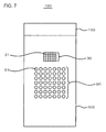
- FIG. 7 is a front view illustrating a folded portable terminal device 100 as an audio output device according to a third embodiment. Meanwhile, even in the third embodiment, a block configuration of the portable terminal device 100 is the same as that of FIG. 2 .
- the structure of the portable terminal device 100 according to the embodiment is different from that of the portable terminal device 100 according to the second embodiment in the following respects.
- the plurality of LEDs 51 are arranged in a line in the second embodiment, the plurality of LEDs 51 are arranged in a matrix in the second embodiment.
- the LED group 50 includes a total of 49 LEDs 51 of 7 rows by 7 columns.
- the LED group 50 and the parametric speaker 30 are disposed in a surface serving as an inner side when the first and second housings 101 and 102 are folded, while in the third embodiment, the LED group 50 and the parametric speaker 30 are disposed in a surface (for example, surface serving as the front side when the second housing 102 is placed on the front side) serving as an outer side when the first and second housings 101 and 102 are folded.
- the LED group 50 and the parametric speaker 30 are provided in the second housing 102.
- another LED group for example, the same one as the LED group 50 in the first embodiment
- another LED group may also be provided in the surface serving as an inner side when the first and second housings 101 and 102 are folded.
- another parametric speaker 30 for example, the same one as the parametric speaker 30 in the first embodiment
- the second embodiment shows the example in which the first and second housings 101 and 102 have a horizontally long shape, that is, a shape in which a turning radius of the first and second housings 101 and 102 when opening or closing the first and second housings 101 and 102 through the hinge unit 103 is shorter than the lengths of the first and second housings 101 and 102 in the axial direction (horizontal direction of FIG. 1 ) of the hinge unit 103.
- the first and second housings 101 and 102 have a vertically long shape, that is, a shape in which the turning radius of the first and second housings 101 and 102 is longer than the lengths of the first and second housings 101 and 102 in the axial direction (horizontal direction of FIG. 7 ) of the hinge unit 103.
- the audio control unit 41 controls the parametric speaker 30 so that an audio image is formed at a position corresponding to the position of the LED 51 emitting light among the plurality of LEDs 51 arranged in a matrix. Meanwhile, similarly to a case where the audio image is formed to correspond to the operation keys 11 (step S12 of FIG. 5 ), the audio image may be formed at a position corresponding to each LED 51, or the audio image may be formed in each zone including the plurality of LEDs 51.
- a further complex and novel decoration than the second embodiment can be implemented through emission and audios.
- FIG. 8 is a front view illustrating a portable terminal device 100 as an audio output device according to a fourth embodiment.
- a plurality of operation units for example, four operation units of 12a, 12b, 12c, and 12d
- the operation unit 12a, the operation unit 12b, the operation unit 2c, and the operation unit 12d can be respectively used for an operation for instructing movement upward, an operation for instructing movement downward, an operation for instructing movement leftward, and an operation for instructing movement rightward.
- the portable terminal device 100 is not limited to the operation key 11 of the keyboard 10 ( FIG. 1 ), and may include other operation buttons 13 ( FIG. 8 ).
- an audio image can be formed at a position corresponding to each of the operated operation units 12a to 12d.
- the audio image can be formed at a position corresponding to the operated operation button 13.
- the oscillator 31 of the portable terminal device 100 according to the embodiment includes an MEMS (Micro Electro Mechanical Systems) actuator 70 shown in FIG. 9 , instead of the vibrator 33 ( FIG. 3 ).
- the portable terminal device 100 according to the embodiment is configured in a similar manner to the portable terminal devices 100 according to the first to fourth embodiments.
- a driving method of the MEMS actuator 70 is a piezoelectric method, and a piezoelectric thin layer 72 is interposed between an upper movable electrode layer 74 and a lower movable electrode layer 76.
- the MEMS actuator 70 is operated by inputting a signal to the upper movable electrode layer 74 and the lower movable electrode layer 76 from the signal generation unit 35.
- the MEMS actuator 70 is manufactured using, for example, an aerosol deposition method, but it is not limited thereto. When the aerosol deposition method is used, the piezoelectric thin layer 72, the upper movable electrode layer 74, and the lower movable electrode layer 76 can also be formed on a curved surface. For this reason, the aerosol deposition method is preferable.
- the driving method of the MEMS actuator 70 may be an electrostatic method, electromagnetic method, or heat conduction method.
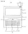
- FIG. 10 is a front view illustrating a portable terminal device 100 as an audio output device according to a sixth embodiment.
- FIG. 11 is a block diagram illustrating the portable terminal device 100 of FIG. 10 .
- FIG. 2 is a schematic diagram illustrating operations for changing a position at which an audio image is formed according to the embodiment.
- the parametric speaker 30 includes, for example, a single (one) oscillator 31, a plurality of the actuators 39 for changing the direction of the oscillator 31, and a supporting unit 39a to which the actuators 39 are fixed.
- the supporting unit 39a is directly or indirectly fixed to a housing (for example, the first housing 101) of the portable terminal device 100.
- the supporting unit 39a is formed, for example, in a flat plate shape.
- the actuators 39 are, for example, piezoelectric elements, and expand and contract by controlling a voltage to be applied.
- One end of each actuator 39 is fixed to the supporting unit 39a, and the other end thereof is fixed to, for example, the supporting member 34 of the oscillator 31.
- the actuators 39 are provided so as to vertically stand up from one surface of the supporting unit 39a.
- a number of actuators 39 can be set to two or three.
- three actuators 39 are provided, a degree of freedom of the adjustment of the direction of the oscillator 31 increases. For this reason, in the embodiment, as shown in FIG. 11 , it is preferable that the parametric speaker 30 have three actuators 39.
- the expansion and contraction operations of the actuators 39 are performed by an actuator control unit 44 ( FIG. 11 ) of the control unit 40.
- FIG. 12 shows operations when the parametric speaker 30 includes two actuators 39.
- any one actuator 39 is contracted (or any one actuator 39 is expanded), thereby allowing an angle of the oscillator 31 with respect to the supporting unit 39a to be changed and allowing the direction in which the ultrasonic waves are output from the oscillator 31 to be changed (in other words, allowing the vibration member 32 to be inclined with respect to the supporting unit 39a). Therefore, the audio image 1 is formed at a position that is offset from the front of the supporting unit 39a ( FIG. 12(b), FIG. 12 (c) ).
- the actuators 39 are appropriately expanded and contracted, thereby allowing the audio image 1 to be formed above the desired operation key 11 or above the desired LED 51.
- the same effects as the first embodiment are obtained.
- the parametric speaker 30 since the position at which the audio image 1 is formed is changed by changing the direction in which the acoustic waves are output from the oscillator 31 using the actuators 39, the parametric speaker 30 does not need to include the plurality of oscillators 31 arranged in an array, and may include, for example, just a single oscillator 31.
- each of the above-described embodiments shows an example that the direction in which an audio is heard is associated with the position of the operation unit which is disposed separately from the display unit 60, when the display unit 60 is a touch panel, the direction in which an audio is heard may be associated with the position of the operation unit formed in the display unit 60.
Landscapes
- Physics & Mathematics (AREA)
- Engineering & Computer Science (AREA)
- Acoustics & Sound (AREA)
- Signal Processing (AREA)
- Health & Medical Sciences (AREA)
- Otolaryngology (AREA)
- Circuit For Audible Band Transducer (AREA)
- Stereophonic System (AREA)
- Telephone Set Structure (AREA)
Abstract
Description
- The present invention relates to an audio output device.
- A parametric speaker is also called a directional speaker, and the like, and has a feature that the directionality of an audio to be output is high. For this reason, an audio image (acoustic field) can be selectively formed in a specific region by using the parametric speaker.
- For example,
Patent Document 1 discloses a technique in which an audio image is constantly located at a predetermined position using a parametric speaker.
In addition, Patent Document 2 discloses a technique in which an audio image is located at a position of an object in an image using a parametric speaker. -
- [Patent Document 1] Japanese Unexamined Patent Publication No.
2010-68023 - [Patent Document 2] Japanese Unexamined Patent Publication No.
2007-274061 - Incidentally, in a general audio output device, when an audio is output in association with a user's operation, the audio is just output with a constant directionality from a speaker.
In addition, even in the technique of Patent Document 2, an audio image is just located at a position of an object in an image. - An object of the invention is to provide an audio output device capable of associating the position of an operation unit which is operated by a user with a direction in which an audio is heard.
- The invention provides an audio output device including: a plurality of operation units that are operated by a user; a detection unit that detects which operation unit of the plurality of operation units is operated; a directional speaker; and an audio control unit that controls the directional speaker so that an audio image is formed at a position corresponding to the position of the operation unit that is operated by the user among the plurality of operation units.
- According to the invention, a direction in which an audio is heard can be associated with a position of an operation unit operated by a user.
- The above-described objects, other objects, features and advantages will be further apparent from the preferred embodiments described below, and the accompanying drawings as follows.
-
-
FIG. 1 is a front view illustrating a portable terminal. device as an audio output device according to a first embodiment. -
FIG. 2 is a block diagram illustrating the portable terminal device ofFIG. 1 . -
FIG. 3 is a schematic diagram illustrating an oscillator included in the portable terminal device ofFIG. 1 . -
FIG. 4 is a cross-sectional view illustrating a layered structure of a vibrator. -
FIG. 5 is a flow chart illustrating a flow of operations according to the first embodiment. -
FIG. 6 is a flow chart illustrating a flow of operations according to a second embodiment. -
FIG. 7 is a front view illustrating a folded portable terminal device as an audio output device according to a third embodiment. -
FIG. 8 is a front view illustrating a portable terminal device as an audio output device according to a fourth embodiment. -
FIG. 9 is an exploded perspective view illustrating a configuration of an MEMS actuator that is used as a vibrator of an oscillator included in a portable terminal device as an audio output device according to a fifth embodiment. -
FIG. 10 is a front view illustrating a portable terminal device as an audio output device according to a sixth embodiment. -
FIG. 11 is a block diagram illustrating the portable terminal device ofFIG. 10 . -
FIG. 12 is a schematic diagram illustrating operations for changing a position at which an audio image is formed according to the sixth embodiment. - Hereinafter, embodiments of the invention will be described in detail with reference to the accompanying drawings. Meanwhile, throughout the drawings, same reference numerals refer to like elements, and the description thereof will not be repeated.
-
FIG. 1 is a front view illustrating aportable terminal device 100 as an audio output device according to a first embodiment.FIG. 2 is a block diagram illustrating theportable terminal device 100 ofFIG. 1 . - The
portable terminal device 100 according to the embodiment includes a plurality of operation units (for example, a plurality of operation keys 11) that are operated by a user, adetection unit 20 that detects which operation unit of the plurality of operations has been operated, a directional speaker (for example, a parametric speaker 30), and anaudio control unit 41 that controls the directional speaker so that an audio image is formed at a position corresponding to the position of the operation unit operated by the user, among the plurality of operation units. Meanwhile, the portable terminal device is, for example, a cellular phone, a PDA (Personal Digital Assistant), a small game machine, or a laptop personal computer, which will be described below in detail. - As shown in
FIG. 1 , theportable terminal device 100 includes a keyboard (operation unit group) 10 having the plurality ofoperation keys 11, and theparametric speaker 30. - The plurality of
operation keys 11 each receives an input of an operation when being pressed by a user, and are arranged, for example, in a matrix. - For example, the
parametric speaker 30 includes a plurality ofoscillators 31 each oscillating ultrasonic waves and arranged in an array. Theoscillators 31 are arranged, for example, in a matrix. Further, theparametric speaker 30 generates an electrical signal to be input to eachoscillator 31. Theparametric speaker 30 is disposed, for example, in the vicinity of thekeyboard 10. - The
portable terminal device 100 further includes an LED group (light-emitting member group) 50 having a plurality of LEDs (light-emitting members) 51, and adisplay unit 60 constituted by a liquid crystal display device or the like. - The
portable terminal device 100 includes, for example, first andsecond housings hinge unit 103 that connects the first andsecond housings keyboard 10 and theparametric speaker 30 are provided in thefirst housing 101, and theLED group 50 and thedisplay unit 60 are provided in thesecond housing 102. Thekeyboard 10, theparametric speaker 30, theLED group 50, and thedisplay unit 60 are all disposed in a surface serving as an inner side when the first andsecond housings - The
LED group 50 is disposed in the vicinity (for example, upper right) of a region in which thedisplay unit 60 is disposed, and includes the plurality of (for example, three)LEDs 51, for example, arranged horizontally in a line. - As shown in
FIG. 2 , theportable terminal device 100 further includes thedetection unit 20 and acontrol unit 40 in addition to thekeyboard 10, theparametric speaker 30, theLED group 50, and thedisplay unit 60. - For example, the
detection unit 20 includes the same number ofdetection switches 21 as theoperation keys 11. When each of thedetection switches 21 detects the operation for thecorresponding operation key 11, thedetection switch 21 outputs a signal indicating the detection (hereinafter, detection signal) to thecontrol unit 40. - The
control unit 40 includes anaudio control unit 41 that individually controls operations of theoscillators 31 of theparametric speaker 30, anemission control unit 42 that individually controls operations of theLEDs 51 of theLED group 50, and adisplay control unit 43 that controls operations of thedisplay unit 60. - The
oscillators 31 of theparametric speaker 30 are controlled by theaudio control unit 41, thereby allowing an audio image to be formed in a desired region. In other words, the audio image can be located in the desired region.
More specifically, theaudio control unit 41 controls theoscillators 31 so that an audio image is formed at a position (for example, above the operation key 11) corresponding to the position of theoperation key 11 that is operated by a user among the plurality ofoperation keys 11. In other words, for example, when anoperation key 11a (FIG. 1 ) is operated, the audio image is formed above theoperation key 11a. In addition, when anoperation key 11b (FIG. 1 ) is operated, the audio image is formed above theoperation key 11b. -
FIG. 3 is a schematic diagram illustrating theoscillator 31. - The
oscillator 31 includes, for example, a sheet-shaped vibration member 32, avibrator 33, and a supportingmember 34. Thevibrator 33 is, for example, a piezoelectric vibrator, and is attached to one surface of thevibration member 32. The supportingmember 34 supports an edge of thevibration member 32. For example, the supportingmember 34 is fixed to a circuit board (not shown) or a housing of theportable terminal device 100.
Thesignal generation unit 35 and theaudio control unit 41 constitute an oscillation circuit that oscillates acoustic waves from thevibrator 33 and thevibration member 32 by inputting an oscillation signal to thevibrator 33 to vibrate thevibrator 33. - The
vibration member 32 vibrates by vibration generated from thevibrator 33, and oscillates acoustic waves, for example, having a frequency equal to or greater than 20 kHz. Meanwhile, thevibrator 33 also oscillates acoustic waves, for example, having a frequency equal to or greater than 20 kHz by its own vibration. In addition, thevibration member 32 adjusts a fundamental resonance frequency of thevibrator 33. A fundamental resonance frequency of a mechanical vibrator depends on load weight and compliance. Since the compliance is mechanical rigidity of the vibrator, the fundamental resonance frequency of thevibrator 33 can be controlled by controlling the rigidity of thevibration member 32. Meanwhile, the thickness of thevibration member 32 is preferably equal to or greater than 5 µm and equal to or less than 500 µm. In addition, it is preferable that thevibration member 32 have a longitudinal elastic modulus, which is an index indicating rigidity, equal to or greater than 1 Gpa and equal to or less than 500 GPa. When the rigidity of thevibration member 32 is excessively low or high, there is a possibility that characteristics and reliability as a mechanical vibrator may be damaged. Meanwhile, the material for forming thevibration member 32 is not particularly limited as long as it is a material, such as a metal or a resin, having a high elastic modulus with respect to thevibrator 33 which is formed of a brittle material, but is preferably phosphor bronze, stainless steel or the like from the viewpoint of workability or costs. - In the embodiment, a planar shape of the
vibrator 33 is a circular shape. However, the planar shape of thevibrator 33 is not limited to the circular shape. The entirety of a surface of thevibrator 33 which faces thevibration member 32 is fixed to thevibration member 32 using an adhesive agent. Accordingly, the entirety of the single-sided surface of thevibrator 33 is restrained by thevibration member 32. - The
signal generation unit 35 generates an electrical signal to be input to thevibrator 33, that is, a modulation signal in theoscillator 31. Carrier waves of the modulation signal are, for example, ultrasonic waves having a frequency equal to or greater than 20 kHz, and specifically are, for example, ultrasonic waves having a frequency of 100 kHz. Theaudio control unit 41 controls thesignal generation unit 35 in response to an audio signal to be input from the outside. -
FIG. 4 is a cross-sectional view illustrating a layered structure in the thickness direction of thevibrator 33. Thevibrator 33 includes apiezoelectric body 36, anupper electrode 37, and alower electrode 38. - The
piezoelectric body 36 is polarized in the thickness direction. The material for forming thepiezoelectric body 36 may be any of an inorganic material or an organic material as long as it is a material having a piezoelectric effect. However, the material is preferably a material having a high electro-mechanical conversion efficiency, for example, lead zirconate titanate (PZT) or barium titanate (BaTiO3). A thickness h1 of thepiezoelectric body 36 is, for example, equal to or greater than 10 µm and equal to or less than 1 mm. When the thickness h1 is less than 10 µm, there is a possibility that thevibrator 33 may be damaged during the manufacturing of theoscillator 31. In addition, when the thickness h1 exceeds 1 mm, there is a possibility that the electro-mechanical conversion efficiency is excessively lowered, and thus a sufficiently large vibration cannot be obtained. The reason is because when the thickness of thevibrator 33 increases, the electric field intensity within the piezoelectric vibrator is inversely proportional thereto and thus decreases. - Although the materials for forming the
upper electrode 37 and thelower electrode 38 are not particularly limited, for example, silver or silver/palladium can be used. Since silver is used as a low-resistance versatile electrode material, there is an advantage in a manufacturing process, cost and the like. Since silver/palladium is a low-resistance material excellent in oxidation resistance, there is an advantage from the viewpoint of reliability. In addition, a thickness h2 of theupper electrode 37 and thelower electrode 38 is not particularly limited, but the thickness h2 is preferably equal to or greater than 1 µm and equal to or less than 50 µm. In the thickness h2 of less than 1 µm, it is difficult to uniformly form theupper electrode 37 and thelower electrode 38. As a result, there is a possibility that the electro-mechanical conversion efficiency decreases. In addition, when the film thicknesses of theupper electrode 37 and thelower electrode 38 exceed 100 µm, theupper electrode 37 and thelower electrode 38 serve as constraint surfaces with respect to thepiezoelectric body 36, and thus there is a possibility that the energy conversion efficiency may decrease. - The
vibrator 33 can be set to have an outer diameter of ϕ18 mm, an inner diameter of ϕ12 mm, and a thickness of 100 µm. In addition, as theupper electrode 37 and thelower electrode 38, for example, a silver/palladium alloy (having a weight ratio of, for example, 7:3) having a thickness of 8 µm can be used. In addition, as thevibration member 32, phosphor bronze having an outer diameter of ϕ20 mm and a thickness of 50 µm (0.3 mm) can be used. The supportingmember 34 serve as a case of theoscillator 31, and is formed, for example, in a tubular shape (for example, cylindrical shape) having an outer diameter of ϕ22 mm and an inner diameter of ϕ20 mm. - The
parametric speaker 30 emits ultrasonic waves (carrier waves) on which an AM modulation, a DSB modulation, an SSB modulation, or an FM modulation is performed from each of the plurality ofoscillators 31 into the air, and issues an audible sound based on the non-linear characteristics when ultrasonic waves are propagated into the air. The term "non-linear" herein indicates a transition from a laminar flow to a turbulent flow when the Reynolds number expressed by the ratio of the inertial action and the viscous action of a flow increases. Since the acoustic wave is very slightly disturbed within a fluid, the acoustic wave is propagated non-linearly. Particularly, in the ultrasonic wave frequency band, the non-linearity of the acoustic wave can be easily observed. When the ultrasonic waves are emitted into the air, higher harmonic waves associated with the non-linearity of the acoustic wave are conspicuously generated. In addition, the acoustic wave is in a sparse and dense state in which light and shade occur in the molecular density in the air. When it takes time for air molecules to be restored rather than compressed, the air which is not capable of being restored after the compression collides with air molecules continuously propagated, and thus a shock wave occurs. The audible sound is generated, that is, reproduced (demodulated) due to the shock wave. Theparametric speaker 30 has an advantage that the directionality of an audio is high. - Hereinafter, a series of operations will be described.
-
FIG. 5 is a flow chart illustrating a flow of operations performed by thecontrol unit 40 according to the first embodiment. - First, a user operates any one operation key 11 (for example, operation key 11a) of the plurality of
operation keys 11. Then, thecontrol unit 40 recognizes the operation of the operation key 11a using the detection signal that is input from thedetection switch 21 corresponding to the operation key 11a (Y of step S11). - Next, the
audio control unit 41 of thecontrol unit 40 controls theparametric speaker 30 so that an audio image is formed at a position corresponding to the position of the operation key 11a, for example, above the operation key 11a, that is, so that the audible sound is demodulated at that position. For example, the phase of the ultrasonic waves output from eachoscillator 31 is controlled, thereby controlling the directionality of theparametric speaker 30 and adjusting the position of the audio image.
As a result, the audio image is located above the operation key 11 (for example, operation key 11a) that is operated by the user (step S12). - Thus, the user hears an audio (operation sound) from the position (direction) of the operation key 11 operated by the user at a timing when the user operates the
operation key 11. Therefore, a novel operational sensation that the position at which the operation sound is heard is associated with the position of theoperation key 11, can be obtained. - In order to implement such operations, for example, the
audio control unit 41 store the value of the phase of the ultrasonic waves output from each oscillator 31 (or value of relative deviation amount of phase of ultrasonic waves output from each oscillator 31) for each of the operation key 11 as a table in advance. Theaudio control unit 41 extracts the value corresponding to the operated operation key 11 from the table, and controls the phase of eachoscillator 31 based on the value.
Meanwhile, the table may, for example, be divided into a first table for determining the position at which the audio image is to be formed in an X coordinate (first direction parallel to display screen) and a second table for determining the position at which the audio image is to be formed in a Y coordinate (direction that is parallel to display screen and perpendicular to the first direction). - In addition, the audios reproduced in step S12 is, for example, a simple audio (for example, blip or the like) to cause the user to recognize the operation of the
operation key 11, and may be a common audio for each of theoperation keys 11.
Alternatively, the audios reproduced in step S12 may be different from each other for theoperation keys 11. In other words, theaudio control unit 41 may control theparametric speaker 30 so that the audio corresponding to the operation key 11 operated by the user is output. The audios different from each other for theoperation keys 11 may be, for example, the same audios as the pronunciation of characters associated with theoperation keys 11. Specifically, for example, in the case of the operation key 11 corresponding to a character "a", an audio "a" may be output. - In addition, in step S12, a resolution of the position at which the audio image is located can be appropriately changed corresponding to a resolution (depending on the number of
oscillators 31, or the like) that can be implemented by theparametric speaker 30. When a fine resolution capable of forming the audio image at different positions according to theoperation keys 11 is obtained, the audio image can be formed at different positions according to each of theoperation keys 11.
Alternatively, when the position of the audio image cannot be controlled very finely, the audio image may be located in each of zones (for example, three zones or Z1, Z2, and Z3 shown inFIG. 1 ) by setting the region in which the plurality ofoperation keys 11 united into one group are disposed as one zone. In other words, the audio image may be located in the zone Z1 when any oneoperation key 11 included in the zone Z1 is operated, the audio image may be located in the zone Z2 when any oneoperation key 11 included in the zone Z2 is operated, and the audio image may be located in the zone Z3 when any oneoperation key 11 included in the zone Z3 is operated. Meanwhile, in this case, at least two zones are set. - In step S13 following step S12, other processes (processes other than the process in step S12) corresponding to the operation are performed. Specifically, for example, the
emission control unit 42 controls theLEDs 51 to emit light in a predetermined emission mode (lighting, blinking, or the like), or thedisplay control unit 43 controls thedisplay unit 60 to display predetermined information, an image, or the like.
Meanwhile, when the operation is not performed (N of step S11) the forming of the audio image (step S12) and other processes (step S13) corresponding to the operation are not performed. - According to the above-described first embodiment, the
detection unit 20 detects whichoperation key 11 of the plurality ofoperation keys 11 is operated by the user, and theaudio control unit 41 controls theparametric speaker 30 so that the audio image is formed at a position corresponding to the position of the operation key 11 operated by the user, and thus a direction in which an audio is heard with respect to the user can be associated with the position of the operation key 11 operated by the user. Therefore, the operation position in the case where there are a plurality ofoperation keys 11 can also be confirmed not only through viewing or touching but also through hearing. -
FIG. 6 is a flow chart illustrating a flow of operations performed by thecontrol unit 40 according to a second embodiment.FIG. 6 illustrates an example of a detailed process of step S13 (FIG. 5 ) described in the first embodiment. In the embodiment, a configuration of the portableterminal device 100 is as shown inFIGS. 1 and2 . - As described above, in step S13 of
FIG. 5 , a process corresponding to the operation (other than the process in step S12) is performed.
Specifically, for example, as shown inFIG. 6 , while theemission control unit 42 performs emission control for causing theLEDs 51 to emit light in a predetermined emission mode (lighting, blinking, or the like) (step S131), theaudio control unit 41 controls theparametric speaker 30 so that an audio image is formed at an emission position (step S132). The emission position refers to a position corresponding to theLED 51 that is emitting light by the emission control, among the plurality ofLEDs 51, and the emission position is, for example, above theLED 51 that is emitting light. A manner of adjusting the position of the audio image is the same as that in step S12.
In addition, further other processes (for example, a process of causing thedisplay control unit 43 to display predetermined information, an image, or the like on the display unit 60) corresponding to the operation are further performed in parallel with the processes of step S131 and step S132 or following these processes (step S133). - As such, in the second embodiment, the portable
terminal device 100 includes the LEDs (light-emitting members) 51 and theemission control unit 42 that controls theLEDs 51. Theaudio control unit 41 controls theparametric speaker 30 so that the audio image is formed at a position corresponding to the position of theLED 51 in association (synchronization) witch the emission operation of theLED 51.
For this reason, a user hears an audio from the position (direction) of theLED 51 emitting light at a timing when theLED 51 emits light. In other words, the direction in which the audio is heard with respect to the user can be associated with the position of theLED 51 emitting light. Therefore, a novel decoration through the emission and the audio can be implemented. -
FIG. 7 is a front view illustrating a folded portableterminal device 100 as an audio output device according to a third embodiment. Meanwhile, even in the third embodiment, a block configuration of the portableterminal device 100 is the same as that ofFIG. 2 . - The structure of the portable
terminal device 100 according to the embodiment is different from that of the portableterminal device 100 according to the second embodiment in the following respects. - First, while the plurality of
LEDs 51 are arranged in a line in the second embodiment, the plurality ofLEDs 51 are arranged in a matrix in the second embodiment. Specifically, for example, theLED group 50 includes a total of 49LEDs 51 of 7 rows by 7 columns. - In addition, in the second embodiment, the
LED group 50 and theparametric speaker 30 are disposed in a surface serving as an inner side when the first andsecond housings LED group 50 and theparametric speaker 30 are disposed in a surface (for example, surface serving as the front side when thesecond housing 102 is placed on the front side) serving as an outer side when the first andsecond housings LED group 50 and theparametric speaker 30 are provided in thesecond housing 102.
However, even in the embodiment, separately from theLED group 50, another LED group (for example, the same one as theLED group 50 in the first embodiment) may also be provided in the surface serving as an inner side when the first andsecond housings
Similarly, even in the embodiment, separately from theparametric speaker 30, another parametric speaker 30 (for example, the same one as theparametric speaker 30 in the first embodiment) may also be provided in the surface serving as the inner side when the first andsecond housings - Meanwhile, the second embodiment shows the example in which the first and
second housings second housings second housings hinge unit 103 is shorter than the lengths of the first andsecond housings FIG. 1 ) of thehinge unit 103.
On the other hand, in the third embodiment, for example, the first andsecond housings second housings second housings FIG. 7 ) of thehinge unit 103. - In the embodiment, the
audio control unit 41 controls theparametric speaker 30 so that an audio image is formed at a position corresponding to the position of theLED 51 emitting light among the plurality ofLEDs 51 arranged in a matrix. Meanwhile, similarly to a case where the audio image is formed to correspond to the operation keys 11 (step S12 ofFIG. 5 ), the audio image may be formed at a position corresponding to eachLED 51, or the audio image may be formed in each zone including the plurality ofLEDs 51. - In addition, for example, the
emission control unit 42 performs a series of emission control operations for causing the plurality ofLEDs 51 to emit light in a predetermined order (emission pattern), thereby allowing illumination to be implemented through the emission of the plurality ofLEDs 51.
Theaudio control unit 41 controls theparametric speaker 30 so that the audio image is formed at a position corresponding to the position of theLED 51 emitting light in association (synchronization) with the emission control. Specifically, for example, when the emission control of the emission pattern in which theLED 51 emitting light moves is performed, it is possible to perform the control in which the position of the audio image moves with the movement of emitting light. - Meanwhile, for example, the control of the
parametric speaker 30 which is associated with the above-described emission control can be performed when the first andsecond housing
Alternatively, the portableterminal device 100 may be a portable terminal device having a communication function, for example, a cellular phone. In this case, the control of theparametric speaker 30 which is associated with the emission control can be performed when a call, an e-mail, or the like arrives. - According to the above-described third embodiment, a further complex and novel decoration than the second embodiment can be implemented through emission and audios.
-
FIG. 8 is a front view illustrating a portableterminal device 100 as an audio output device according to a fourth embodiment. Although each of the above-described embodiments shows an example in which it is assumed that the operation units (operation keys 11) are individually formed and operated by being individually pressed, a plurality of operation units (for example, four operation units of 12a, 12b, 12c, and 12d) may be integrally formed, for example, like cross key 12 shown inFIG. 8 . Like thegeneral cross key 12, for example, theoperation unit 12a, theoperation unit 12b, the operation unit 2c, and theoperation unit 12d can be respectively used for an operation for instructing movement upward, an operation for instructing movement downward, an operation for instructing movement leftward, and an operation for instructing movement rightward. In addition, the portableterminal device 100 is not limited to theoperation key 11 of the keyboard 10 (FIG. 1 ), and may include other operation buttons 13 (FIG. 8 ). - In the embodiment, when the
operation units 12a to 12d of the cross key 12 are operated, an audio image can be formed at a position corresponding to each of the operatedoperation units 12a to 12d. Alternatively, when any oneoperation button 13 is operated, the audio image can be formed at a position corresponding to the operatedoperation button 13. - The
oscillator 31 of the portableterminal device 100 according to the embodiment includes an MEMS (Micro Electro Mechanical Systems)actuator 70 shown inFIG. 9 , instead of the vibrator 33 (FIG. 3 ). In other respects, the portableterminal device 100 according to the embodiment is configured in a similar manner to the portableterminal devices 100 according to the first to fourth embodiments. - In an example shown in
FIG. 9 , a driving method of theMEMS actuator 70 is a piezoelectric method, and a piezoelectricthin layer 72 is interposed between an uppermovable electrode layer 74 and a lowermovable electrode layer 76. TheMEMS actuator 70 is operated by inputting a signal to the uppermovable electrode layer 74 and the lowermovable electrode layer 76 from thesignal generation unit 35. TheMEMS actuator 70 is manufactured using, for example, an aerosol deposition method, but it is not limited thereto. When the aerosol deposition method is used, the piezoelectricthin layer 72, the uppermovable electrode layer 74, and the lowermovable electrode layer 76 can also be formed on a curved surface. For this reason, the aerosol deposition method is preferable. Meanwhile, the driving method of theMEMS actuator 70 may be an electrostatic method, electromagnetic method, or heat conduction method. -
FIG. 10 is a front view illustrating a portableterminal device 100 as an audio output device according to a sixth embodiment.FIG. 11 is a block diagram illustrating the portableterminal device 100 ofFIG. 10 .FIG. 2 is a schematic diagram illustrating operations for changing a position at which an audio image is formed according to the embodiment. - Each of the above-described embodiments shows an example in which a position at which the audio image is formed is controlled by controlling the phase of the ultrasonic waves output from each
oscillator 31 of theparametric speaker 30.
On the other hand, in the embodiment, a direction in which acoustic waves are output from theoscillator 31 is changed using anactuator 39 so as to control the directionality of theparametric speaker 30 and to control the position at which the audio image is formed, that is, the position at which the audio sound is demodulated. - In the embodiment, the
parametric speaker 30 includes, for example, a single (one)oscillator 31, a plurality of theactuators 39 for changing the direction of theoscillator 31, and a supportingunit 39a to which theactuators 39 are fixed. - The supporting
unit 39a is directly or indirectly fixed to a housing (for example, the first housing 101) of the portableterminal device 100. The supportingunit 39a is formed, for example, in a flat plate shape. - The
actuators 39 are, for example, piezoelectric elements, and expand and contract by controlling a voltage to be applied. One end of each actuator 39 is fixed to the supportingunit 39a, and the other end thereof is fixed to, for example, the supportingmember 34 of theoscillator 31. For example, as shown inFIG. 12 , theactuators 39 are provided so as to vertically stand up from one surface of the supportingunit 39a. - A number of
actuators 39 can be set to two or three. When threeactuators 39 are provided, a degree of freedom of the adjustment of the direction of theoscillator 31 increases. For this reason, in the embodiment, as shown inFIG. 11 , it is preferable that theparametric speaker 30 have threeactuators 39. The expansion and contraction operations of theactuators 39 are performed by an actuator control unit 44 (FIG. 11 ) of thecontrol unit 40. - For the convenience of description,
FIG. 12 shows operations when theparametric speaker 30 includes twoactuators 39. - When the
actuators 39 have the same length, the direction in which the ultrasonic waves are output from theoscillator 31 is set to be an opposite direction to the supportingunit 39a (in other words, thevibration member 32 of theoscillator 31 is parallel to the supportingunit 39a). Therefore, anaudio image 1 is formed in the front direction of the supportingunit 39a (FIG. 12(a) ). - In addition, any one
actuator 39 is contracted (or any oneactuator 39 is expanded), thereby allowing an angle of theoscillator 31 with respect to the supportingunit 39a to be changed and allowing the direction in which the ultrasonic waves are output from theoscillator 31 to be changed (in other words, allowing thevibration member 32 to be inclined with respect to the supportingunit 39a). Therefore, theaudio image 1 is formed at a position that is offset from the front of the supportingunit 39a (FIG. 12(b), FIG. 12 (c) ). - Therefore, in the embodiment, the
actuators 39 are appropriately expanded and contracted, thereby allowing theaudio image 1 to be formed above the desired operation key 11 or above the desiredLED 51. - According to the sixth embodiment, the same effects as the first embodiment are obtained.
In addition, in the sixth embodiment, since the position at which theaudio image 1 is formed is changed by changing the direction in which the acoustic waves are output from theoscillator 31 using theactuators 39, theparametric speaker 30 does not need to include the plurality ofoscillators 31 arranged in an array, and may include, for example, just asingle oscillator 31. - Although each of the above-described embodiments shows an example that the direction in which an audio is heard is associated with the position of the operation unit which is disposed separately from the
display unit 60, when thedisplay unit 60 is a touch panel, the direction in which an audio is heard may be associated with the position of the operation unit formed in thedisplay unit 60. - The application is based on Japanese Patent Application No.
2011-020330 filed on February 2, 2011
Claims (8)
- An audio output device comprising:a plurality of operation units that are operated by a user;a detection unit that detects which operation unit of the plurality of operation units is operated;a directional speaker; andan audio control unit that controls the directional speaker so that an audio image is formed at a position corresponding to the position of the operation unit operated by the user among the plurality of operation units.
- The audio output device according to claim 1,
wherein the audio control unit controls the directional speaker so that an audio corresponding to the operation unit operated by the user is output. - The audio output device according to claim 1 or 2,
wherein at least one of the plurality of operation units is an operation key. - The audio output device according to any one of claims 1 to 3,
wherein the directional speaker is a parametric speaker. - The audio output device according to any one of claims 1 to 4, further comprising:a light-emitting member; andan emission control unit that controls the light-emitting member,wherein the audio control unit controls the directional speaker so that the audio image is formed at a position corresponding to the position of the light-emitting member in association with the emission operation of the light-emitting member.
- The audio output device according to claim 5, further comprising a plurality of the light-emitting members which are arranged in a matrix,
wherein the audio control unit controls the directional speaker so that the audio image is formed at the position corresponding to the position of the light-emitting member that emits light among the plurality of light-emitting members. - The audio output device according to claim 6,
wherein the emission control unit performs a series of emission control operations for causing the plurality of light-emitting members to emit light in a predetermined order. - The audio output device according to any one of claims 1 to 7,
wherein the audio output device is a portable terminal device.
Applications Claiming Priority (2)
| Application Number | Priority Date | Filing Date | Title |
|---|---|---|---|
| JP2011020330A JP5725542B2 (en) | 2011-02-02 | 2011-02-02 | Audio output device |
| PCT/JP2012/000435 WO2012105183A1 (en) | 2011-02-02 | 2012-01-24 | Audio output device |
Publications (2)
| Publication Number | Publication Date |
|---|---|
| EP2672734A1 true EP2672734A1 (en) | 2013-12-11 |
| EP2672734A4 EP2672734A4 (en) | 2015-01-28 |
Family
ID=46602410
Family Applications (1)
| Application Number | Title | Priority Date | Filing Date |
|---|---|---|---|
| EP12742510.6A Withdrawn EP2672734A4 (en) | 2011-02-02 | 2012-01-24 | Audio output device |
Country Status (5)
| Country | Link |
|---|---|
| US (1) | US9215523B2 (en) |
| EP (1) | EP2672734A4 (en) |
| JP (1) | JP5725542B2 (en) |
| CN (1) | CN103348704B (en) |
| WO (1) | WO2012105183A1 (en) |
Families Citing this family (8)
| Publication number | Priority date | Publication date | Assignee | Title |
|---|---|---|---|---|
| US10181314B2 (en) * | 2013-03-15 | 2019-01-15 | Elwha Llc | Portable electronic device directed audio targeted multiple user system and method |
| US10291983B2 (en) * | 2013-03-15 | 2019-05-14 | Elwha Llc | Portable electronic device directed audio system and method |
| US9886941B2 (en) | 2013-03-15 | 2018-02-06 | Elwha Llc | Portable electronic device directed audio targeted user system and method |
| US10575093B2 (en) | 2013-03-15 | 2020-02-25 | Elwha Llc | Portable electronic device directed audio emitter arrangement system and method |
| US20140269214A1 (en) | 2013-03-15 | 2014-09-18 | Elwha LLC, a limited liability company of the State of Delaware | Portable electronic device directed audio targeted multi-user system and method |
| US9763021B1 (en) * | 2016-07-29 | 2017-09-12 | Dell Products L.P. | Systems and methods for display of non-graphics positional audio information |
| CN106507006A (en) * | 2016-11-15 | 2017-03-15 | 四川长虹电器股份有限公司 | Intelligent television orients transaudient System and method for |
| JP6897480B2 (en) * | 2017-10-12 | 2021-06-30 | オムロン株式会社 | Operation switch unit and gaming machine |
Family Cites Families (15)
| Publication number | Priority date | Publication date | Assignee | Title |
|---|---|---|---|---|
| JPH03264883A (en) | 1990-03-15 | 1991-11-26 | Matsushita Electric Works Ltd | Information apparatus |
| JP2000082162A (en) * | 1998-09-04 | 2000-03-21 | Toshiba Corp | Information input / output device and automatic transaction device |
| EP1035732A1 (en) * | 1998-09-24 | 2000-09-13 | Fourie Inc. | Apparatus and method for presenting sound and image |
| JP2000285709A (en) * | 1999-03-29 | 2000-10-13 | Toyoda Gosei Co Ltd | Sound illumination device |
| US6882337B2 (en) * | 2002-04-18 | 2005-04-19 | Microsoft Corporation | Virtual keyboard for touch-typing using audio feedback |
| US7363060B2 (en) * | 2003-05-02 | 2008-04-22 | Nokia Corporation | Mobile telephone user interface |
| JP4333385B2 (en) * | 2004-02-03 | 2009-09-16 | セイコーエプソン株式会社 | Super-directional speaker, projector, and portable information terminal |
| JP4347743B2 (en) * | 2004-05-11 | 2009-10-21 | パイオニア株式会社 | Sound generator, method thereof, program thereof, and recording medium recording the program |
| JP4904793B2 (en) * | 2005-12-05 | 2012-03-28 | 株式会社Jvcケンウッド | Electronic book, control method and program |
| JP2007274061A (en) | 2006-03-30 | 2007-10-18 | Yamaha Corp | Sound image localizer and av system |
| WO2007144014A1 (en) * | 2006-06-15 | 2007-12-21 | Nokia Corporation | Mobile device with virtual keypad |
| JP2010041167A (en) * | 2008-08-01 | 2010-02-18 | Seiko Epson Corp | Voice output controller, sound output device, voice output control method, and program |
| JP2010068023A (en) | 2008-09-08 | 2010-03-25 | Mitsubishi Electric Engineering Co Ltd | Virtual surround audio system |
| JP2011055076A (en) | 2009-08-31 | 2011-03-17 | Fujitsu Ltd | Voice communication device and voice communication method |
| US9092056B2 (en) * | 2010-02-22 | 2015-07-28 | Panasonic Corporation Of North America | Keyboard having selectively viewable glyphs |
-
2011
- 2011-02-02 JP JP2011020330A patent/JP5725542B2/en active Active
-
2012
- 2012-01-24 CN CN201280007355.2A patent/CN103348704B/en not_active Expired - Fee Related
- 2012-01-24 US US13/981,034 patent/US9215523B2/en not_active Expired - Fee Related
- 2012-01-24 EP EP12742510.6A patent/EP2672734A4/en not_active Withdrawn
- 2012-01-24 WO PCT/JP2012/000435 patent/WO2012105183A1/en not_active Ceased
Also Published As
| Publication number | Publication date |
|---|---|
| US20130294637A1 (en) | 2013-11-07 |
| JP5725542B2 (en) | 2015-05-27 |
| WO2012105183A1 (en) | 2012-08-09 |
| EP2672734A4 (en) | 2015-01-28 |
| US9215523B2 (en) | 2015-12-15 |
| CN103348704A (en) | 2013-10-09 |
| JP2012160983A (en) | 2012-08-23 |
| CN103348704B (en) | 2016-03-30 |
Similar Documents
| Publication | Publication Date | Title |
|---|---|---|
| US9215523B2 (en) | Audio output device | |
| JP4968515B2 (en) | Substrate support vibration structure, input device with tactile function, and electronic device | |
| US8310452B2 (en) | Touch panel display apparatus, electronic device having touch panel display apparatus, and camera having touch panel display apparatus | |
| US9386367B2 (en) | Electronic apparatus with detachable speakers, a body unit and a control unit | |
| JP4770164B2 (en) | Piezoelectric support structure, piezoelectric body mounting method, input device with tactile function, and electronic device | |
| CN102986249A (en) | Vibration device and electronic device | |
| US9313565B2 (en) | Portable terminal device having sound emission hole which changes orientation based on rotation of casing about biaxial hinge | |
| JP6073071B2 (en) | Electronics | |
| JP2012108949A (en) | Substrate supporting vibration structure, input device with tactile function, and electronic device | |
| US9348442B2 (en) | Input apparatus | |
| JP6000642B2 (en) | Electronics | |
| JP6021184B2 (en) | Electronic equipment | |
| JP2012034120A (en) | Portable terminal device | |
| KR102340299B1 (en) | Actuator for distributed mode loudspeaker with extended damper and system comprising same | |
| JP2013020362A (en) | Input unit, display unit, and device | |
| JP5609384B2 (en) | Mobile terminal device | |
| JP2013242803A (en) | Electronic apparatus | |
| JP2012181826A (en) | Electronic apparatus and portable terminal with the same | |
| JP2012029094A (en) | Mobile terminal device | |
| JP2013242806A (en) | Electronic apparatus | |
| JP6175220B2 (en) | Electronics | |
| JP2013242814A (en) | Electronic apparatus | |
| JP2012029097A (en) | Sound output device | |
| JP2013243617A (en) | Electronic apparatus | |
| JP2012034121A (en) | Portable terminal device |
Legal Events
| Date | Code | Title | Description |
|---|---|---|---|
| PUAI | Public reference made under article 153(3) epc to a published international application that has entered the european phase |
Free format text: ORIGINAL CODE: 0009012 |
|
| 17P | Request for examination filed |
Effective date: 20130814 |
|
| AK | Designated contracting states |
Kind code of ref document: A1 Designated state(s): AL AT BE BG CH CY CZ DE DK EE ES FI FR GB GR HR HU IE IS IT LI LT LU LV MC MK MT NL NO PL PT RO RS SE SI SK SM TR |
|
| DAX | Request for extension of the european patent (deleted) | ||
| A4 | Supplementary search report drawn up and despatched |
Effective date: 20150108 |
|
| RIC1 | Information provided on ipc code assigned before grant |
Ipc: H04R 17/00 20060101ALI20141222BHEP Ipc: H04S 7/00 20060101ALI20141222BHEP Ipc: H04S 1/00 20060101ALI20141222BHEP Ipc: H04R 1/32 20060101ALI20141222BHEP Ipc: H04R 3/00 20060101AFI20141222BHEP Ipc: H04N 21/439 20110101ALI20141222BHEP Ipc: H04R 3/12 20060101ALI20141222BHEP Ipc: H01H 13/83 20060101ALI20141222BHEP Ipc: H04N 5/60 20060101ALI20141222BHEP Ipc: H04R 1/40 20060101ALI20141222BHEP Ipc: H04N 21/431 20110101ALI20141222BHEP Ipc: H01H 13/84 20060101ALI20141222BHEP Ipc: H04N 21/442 20110101ALI20141222BHEP Ipc: H04N 21/422 20110101ALI20141222BHEP |
|
| RAP1 | Party data changed (applicant data changed or rights of an application transferred) |
Owner name: NEC CORPORATION |
|
| STAA | Information on the status of an ep patent application or granted ep patent |
Free format text: STATUS: THE APPLICATION HAS BEEN WITHDRAWN |
|
| 18W | Application withdrawn |
Effective date: 20180216 |