EP2672392A1 - Collision detection in eia-485 bus systems - Google Patents
Collision detection in eia-485 bus systems Download PDFInfo
- Publication number
- EP2672392A1 EP2672392A1 EP12170846.5A EP12170846A EP2672392A1 EP 2672392 A1 EP2672392 A1 EP 2672392A1 EP 12170846 A EP12170846 A EP 12170846A EP 2672392 A1 EP2672392 A1 EP 2672392A1
- Authority
- EP
- European Patent Office
- Prior art keywords
- transmission line
- bit
- voltage
- transmitter
- eia
- Prior art date
- Legal status (The legal status is an assumption and is not a legal conclusion. Google has not performed a legal analysis and makes no representation as to the accuracy of the status listed.)
- Withdrawn
Links
Images


Classifications
-
- G—PHYSICS
- G06—COMPUTING OR CALCULATING; COUNTING
- G06F—ELECTRIC DIGITAL DATA PROCESSING
- G06F13/00—Interconnection of, or transfer of information or other signals between, memories, input/output devices or central processing units
- G06F13/14—Handling requests for interconnection or transfer
- G06F13/36—Handling requests for interconnection or transfer for access to common bus or bus system
-
- G—PHYSICS
- G06—COMPUTING OR CALCULATING; COUNTING
- G06F—ELECTRIC DIGITAL DATA PROCESSING
- G06F13/00—Interconnection of, or transfer of information or other signals between, memories, input/output devices or central processing units
- G06F13/38—Information transfer, e.g. on bus
- G06F13/42—Bus transfer protocol, e.g. handshake; Synchronisation
- G06F13/4282—Bus transfer protocol, e.g. handshake; Synchronisation on a serial bus, e.g. I2C bus, SPI bus
- G06F13/4286—Bus transfer protocol, e.g. handshake; Synchronisation on a serial bus, e.g. I2C bus, SPI bus using a handshaking protocol, e.g. RS232C link
-
- G—PHYSICS
- G06—COMPUTING OR CALCULATING; COUNTING
- G06F—ELECTRIC DIGITAL DATA PROCESSING
- G06F13/00—Interconnection of, or transfer of information or other signals between, memories, input/output devices or central processing units
- G06F13/38—Information transfer, e.g. on bus
- G06F13/40—Bus structure
- G06F13/4063—Device-to-bus coupling
- G06F13/4068—Electrical coupling
- G06F13/4072—Drivers or receivers
-
- H—ELECTRICITY
- H04—ELECTRIC COMMUNICATION TECHNIQUE
- H04L—TRANSMISSION OF DIGITAL INFORMATION, e.g. TELEGRAPHIC COMMUNICATION
- H04L25/00—Baseband systems
- H04L25/02—Details ; arrangements for supplying electrical power along data transmission lines
- H04L25/0264—Arrangements for coupling to transmission lines
- H04L25/028—Arrangements specific to the transmitter end
Definitions
- the invention relates to the field of data communication over bus systems according to RS-485, and specifically to message collision detection in such systems.
- the EIA-485 (also referred to as RS-485) standard defines a balanced multi-drop communication which can be used by different types of serial communication protocols. EIA-485 is concerned with the electrical characteristics of the interface and does not specify a particular protocol, nor does it refer to a specific connector or collision detection or collision avoidance technique.
- a bus system according to EIA-485 may comprise up to 32 (unit load) devices and the length of the bus may be up to 1200 meters with Baud rates of 115200 bits/s or higher.
- EIA-485 is specified as Half Duplex (HD) transmission, the communication can become Full Duplex (FD) by applying a four wire connection.
- HD Half Duplex
- FD Full Duplex
- Colliding messages significantly reduce the data throughput on every communication link. Firstly, at least two messages are lost in a collision. Secondly, most protocols have retransmission techniques in place which may lead to further collisions. Ideally, collisions should be avoided using suitable collision avoidance techniques such as Carrier Sense Multiple Access (CSMA) with Collision Avoidance. But even with a good collision avoidance measure, collisions can still occur and should be detected properly.
- CSMA Carrier Sense Multiple Access
- DNP 3.0 which allows slaves transmitting messages in an uncoordinated manner (called "DNP unsolicited mode").
- DNP unsolicited mode it is imperative to recognize collisions, as any data rate degradation on the bus is not acceptable especially if high priority event messages need to be sent.
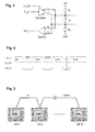
- Fig.1 depicts a typical HD setup with an EIA-485 transceiver connected to a bus including positive wire A and negative wire B.
- permanent pull-up and pull-down resistors R A , R B are provided respectively between wire A and Vcc (e.g. 3.3 or 5 Volts) and between wire B and GND (ground), in order to bias the data lines into a defined state.
- a termination resistor R T may be used at the bus ends to avoid reflections caused by high Baud rates and fast slew rates.
- Fig.2 depicts a typical timing diagram for the transceiver wiring of Fig. 1 , with '1' being called 'mark' and '0' being called ⁇ space'.
- '1' being called 'mark'
- '0' being called ⁇ space'.
- the start bit is '0' (space)
- the stop bit again is '1' (mark). Therefore, there will always be a transition from mark to space at the start of every word. This way the receiver can always synchronise its clock regardless of the data content.
- EIA-485 implementations include a software-based collision detection principle where the transmit data TX_D, which was provided e.g. by a Universal Asynchronous Receiver / Transmitter (UART), is compared against receive data RX_D recorded by the receiver during transmission of the transmit data TX_D. If the data does not correlate, occurrence of a collision is signalled. However, such a solution is only suitable if the colliding signal superposes the transmit signal sufficiently. In an EIA-485 setup with a long transmission line exceeding a few hundred meters, and/or with a cable of bad quality, one transmitter may appear stronger than the other. Specifically, a collision may remain undetected in case two transmitters are located at far ends of the bus.
- UART Universal Asynchronous Receiver / Transmitter
- Fig.3 depicts an exemplary set-up of an EIA-485 bus system with a bus length of 1000m and including two neighboring IEDs 1 and 2 as well as remote IED 32.
- Fig.4 shows the result of a transmission over the bus system of Fig.3 , wherein IED 1 is receiving, while IED 2 and IED 32 are both transmitting.
- the four signals displayed include, from top to bottom, the transmitted signal from IED 2 (TX2_D), the signal transmitted from the remote IED 32 (TX32_D), a resulting superposition signal on the bus in the vicinity of IED 1 and IED 2 (Vbus), and the received signal at the RS-485 receiver inside IED 1 as obtained from Vbus by discrimination (RX1_D).
- TX32_D is not strong enough to significantly influence Vbus. In other words, TX2_D dominates and masks the collision with the messages from remote IED 32.
- the EIA-485 transceivers in IED 2 and IED 32 drive their signals with the same strength.
- the impedance of the transmission line however reduces the signal energy from IED 32 as it travels from one bus end to the other. When arriving at IED 1 and IED 2, the signal is not strong enough to superimpose the local signal sufficiently.
- a communication module for Intelligent Electronic Devices (IEDs) implementing the EIA-485 standard is provided with an intelligent hardware support that allows a conventional software-based collision detection function to detect collisions independently of the location of the message sources on the transmission line.
- the hardware support enables both a "strong signal driving” mode as well as a “weak signal driving” mode.
- an EIA-485 biasing, or attenuating, or voltage-dividing, resistor is temporarily inserted between a transmitter, or voltage source, and the transmission line.
- active bits such as any start bit and any 'space' or '0' data bit are transmitted in strong mode.
- the strong mode is likewise enabled, following which the transmission mode changes to the weak mode by activating the biasing resistor. This ultimately allows detecting a collision provoked by another transmitter.
- the proposed collision detection facilitation technique is used in conjunction with a suitable collision avoidance mechanism such as CSMA.
- message collision detection in communication bus systems operating according to EIA-485 wherein a signal transmitter is connected to two wires of a transmission line for transmitting a binary signal including a first bit ("space") followed by a second bit (“mark”) different from the first bit, comprises the steps of
- the third voltage is applied to the transmission line by a weak-mode transmitter different from the transmitter applying the second voltage.
- the biasing resistors are permanently arranged between the weak-mode transmitter and the transmission line, and thus do not need to be switched or otherwise activated/deactivated.
- the second voltage has a reverse polarity, or an opposite sign, of the first voltage and the duration of the transitional period is sufficient to reverse the polarity of the transmission line over the entire length of the line.
- the transitional period is generally shorter than five microseconds, in particular shorter than 2 microseconds, and typically equal to about one microsecond.
- Fig.5 depicts an exemplary EIA-485 HD setup according to the invention.
- Two preferably identical transmitters or line drivers are used in this configuration.
- Primary transmitter 10 remains unchanged with respect to the configuration of Fig.1 , with output Y1 of primary transmitter 10 being connected to wire A of the transmission line, and output Z1 being connected to wire B.
- Receiver 11 has a first input A1 connected to wire A and a second input B1 connected to wire B.
- Biasing transmitter 20 is connected to the transmission line in parallel to the primary transmitter 10 and via biasing resistors RA, RB. Specifically, output Y2 of biasing transmitter 20 is connected via first biasing resistor RA to wire A of the transmission line, while output Z2 is connected via biasing resistor RB to wire B.
- Data signals TX_D and BIAS_POL are input to the two RS-485 transmitters 10, 20, wherein the transmit data stream TX_D of the primary transmitter is preferably used as an input for the biasing transmitter BIAS_POL as well.
- the two line drivers are connected to a dedicated Programmable Gate Array (FPGA or CPLD, not depicted) providing the required control signals TX_EN and BIAS_EN.
- Operation of the biasing resistors RA, RB is controlled by the transmitters to drive the transmission line in a "weak mode" during selected "sensitive” or “vulnerable” periods.
- Weak driving includes applying the driving voltage of the transmitter in series to the biasing resistors and to the transmission line. Accordingly, a voltage drop at the biasing resistors becomes comparable in magnitude to a voltage drop suffered by an unbiased driving voltage applied at a remote end of the transmission line.
- a receiver connected to the transmission line between the biasing resistors and the remote transmitter will thus be able to detect a derivation or derogation of the transmitted signal due to superposition by a colliding signal. Thus a colliding signal is detected at the sending device and a collision may be signalled.
- the shaded rectangles in Fig.5 denote alternative locations for the biasing resistors in a single-transceiver variant without a dedicated biasing transmitter 20.
- the biasing resistors are inserted between the outputs Y1 and Z1 of the first transmitter and the respective bifurcation point (T-point) on the wire A, B connecting to receiver inputs. Biasing resistors inserted in such alternative locations must be bypassed or otherwise deactivated in strong driving mode.
- Fig.6 depicts an exemplary timing diagram for the transceiver wiring shown in Fig.5 .
- the transmit enable pin TX_EN of the primary line driver is active just as long as it is needed for transmitting the "space” and for shifting the voltage level, or polarity, from “space” to "mark".
- the primary transmitter 10 is disabled.
- the permanently enabled biasing transmitter 20 weakly drives the transmitted signal.
- the RX1_D signal only reduces insignificantly when passing from strong to weak driving mode.
- biasing enable pin BIAS_EN of the biasing driver is active from the start bit until some pre-set time after the last character has left the UART ("Byte enable").
- the bias support should be disabled shortly after the message was sent in order not to overload the bus with multiple "bias supporters".
- biasing resistor values depends on the type of transmission line, i.e. the cable characteristic impedance. Accordingly, the value chosen is allowed to somewhat derogate from the standard 120 Ohm, but is generally perceived to remain between 100 to 150 Ohm.
- Fig. 7 shows the result of a modified transmission over the bus system of Fig.3 , with IED 2 and IED 32 both transmitting.
- the four signals depicted include, from top to bottom, the signals transmitted from IED 2 (TX2_D) and from remote IED 32 (TX32_D), a resulting superimposed signal on the bus at or close to IED 2 (Vbus), as well as, derived from the former, the receive signal (RX2_D) determined by the receiver inside IED 2. Due to the biasing resistors of IED 2, the signal transmitted from remote IED 32 has a noticeable influence at IED 2.
- IED 2 may determine a discrepancy between transmit signal and receive signal, and conclude that a collision has occurred.
- the time scale corresponds to a bit length of a few milliseconds and a Baud rate of 300. For this reason, the initial strong driving part lasting for a few microseconds leads only to a narrow spike in the superposition signal and the receive signal at t1.
Landscapes
- Engineering & Computer Science (AREA)
- Theoretical Computer Science (AREA)
- General Engineering & Computer Science (AREA)
- Physics & Mathematics (AREA)
- General Physics & Mathematics (AREA)
- Power Engineering (AREA)
- Computer Networks & Wireless Communication (AREA)
- Signal Processing (AREA)
- Computer Hardware Design (AREA)
- Small-Scale Networks (AREA)
- Dc Digital Transmission (AREA)
- Arrangements For Transmission Of Measured Signals (AREA)
Abstract
The present invention is concerned with a communication module for Intelligent Electronic Devices (IEDs) implementing the EIA-485 standard, and featuring an intelligent hardware support that allows a conventional software-based collision detection function to detect collisions independently of the location of the message sources on the transmission line. The hardware support enables both a "strong signal driving" mode as well as a "weak signal driving" mode. In the weak mode, a biasing, or attenuating, or voltage-dividing, resistor is temporarily inserted between a transmitter, or voltage source, and the transmission line.
Description
- The invention relates to the field of data communication over bus systems according to RS-485, and specifically to message collision detection in such systems.
- The EIA-485 (also referred to as RS-485) standard defines a balanced multi-drop communication which can be used by different types of serial communication protocols. EIA-485 is concerned with the electrical characteristics of the interface and does not specify a particular protocol, nor does it refer to a specific connector or collision detection or collision avoidance technique. A bus system according to EIA-485 may comprise up to 32 (unit load) devices and the length of the bus may be up to 1200 meters with Baud rates of 115200 bits/s or higher. Although EIA-485 is specified as Half Duplex (HD) transmission, the communication can become Full Duplex (FD) by applying a four wire connection.
- Colliding messages significantly reduce the data throughput on every communication link. Firstly, at least two messages are lost in a collision. Secondly, most protocols have retransmission techniques in place which may lead to further collisions. Ideally, collisions should be avoided using suitable collision avoidance techniques such as Carrier Sense Multiple Access (CSMA) with Collision Avoidance. But even with a good collision avoidance measure, collisions can still occur and should be detected properly.
- Within Substation Automation Systems, a protocol which is often used via, or over, EIA-485 is DNP 3.0 which allows slaves transmitting messages in an uncoordinated manner (called "DNP unsolicited mode"). In this case, it is imperative to recognize collisions, as any data rate degradation on the bus is not acceptable especially if high priority event messages need to be sent.
-
Fig.1 depicts a typical HD setup with an EIA-485 transceiver connected to a bus including positive wire A and negative wire B. In order to ensure a fail-safe EIA-485 communication, permanent pull-up and pull-down resistors RA, RB are provided respectively between wire A and Vcc (e.g. 3.3 or 5 Volts) and between wire B and GND (ground), in order to bias the data lines into a defined state. A termination resistor RT may be used at the bus ends to avoid reflections caused by high Baud rates and fast slew rates. -
Fig.2 depicts a typical timing diagram for the transceiver wiring ofFig. 1 , with '1' being called 'mark' and '0' being called `space'. As long as there is no traffic on the line (idle state), the line is transmitting marks or '1' continuously. The start bit is '0' (space) and the stop bit again is '1' (mark). Therefore, there will always be a transition from mark to space at the start of every word. This way the receiver can always synchronise its clock regardless of the data content. - Many EIA-485 implementations include a software-based collision detection principle where the transmit data TX_D, which was provided e.g. by a Universal Asynchronous Receiver / Transmitter (UART), is compared against receive data RX_D recorded by the receiver during transmission of the transmit data TX_D. If the data does not correlate, occurrence of a collision is signalled. However, such a solution is only suitable if the colliding signal superposes the transmit signal sufficiently. In an EIA-485 setup with a long transmission line exceeding a few hundred meters, and/or with a cable of bad quality, one transmitter may appear stronger than the other. Specifically, a collision may remain undetected in case two transmitters are located at far ends of the bus.
-
Fig.3 depicts an exemplary set-up of an EIA-485 bus system with a bus length of 1000m and including two neighboringIEDs -
Fig.4 shows the result of a transmission over the bus system ofFig.3 , wherein IED 1 is receiving, while IED 2 and IED 32 are both transmitting. The four signals displayed include, from top to bottom, the transmitted signal from IED 2 (TX2_D), the signal transmitted from the remote IED 32 (TX32_D), a resulting superposition signal on the bus in the vicinity ofIED 1 and IED 2 (Vbus), and the received signal at the RS-485 receiver insideIED 1 as obtained from Vbus by discrimination (RX1_D). As apparent from RX1_D, TX32_D is not strong enough to significantly influence Vbus. In other words, TX2_D dominates and masks the collision with the messages from remote IED 32. - It is important to note that the EIA-485 transceivers in IED 2 and IED 32 drive their signals with the same strength. The impedance of the transmission line however reduces the signal energy from IED 32 as it travels from one bus end to the other. When arriving at
IED 1 andIED 2, the signal is not strong enough to superimpose the local signal sufficiently. - It is an objective of the invention to facilitate message collision detection in communication bus systems operating according to EIA-485, in particular in Substation Automation systems with extended communication bus topologies including transmission line distances between two message sources in excess of a few hundred meters. This objective is achieved by a method of facilitating message collision detection and a communication module according to the independent claims. Preferred embodiments are evident from the dependent patent claims, wherein the claim dependency shall not be construed as excluding further meaningful claim combinations.
- According to an aspect of the invention, a communication module for Intelligent Electronic Devices (IEDs) implementing the EIA-485 standard is provided with an intelligent hardware support that allows a conventional software-based collision detection function to detect collisions independently of the location of the message sources on the transmission line. The hardware support enables both a "strong signal driving" mode as well as a "weak signal driving" mode. In the weak mode, an EIA-485 biasing, or attenuating, or voltage-dividing, resistor is temporarily inserted between a transmitter, or voltage source, and the transmission line.
- By way of example, active bits such as any start bit and any 'space' or '0' data bit are transmitted in strong mode. During a transitional period at the beginning of each "mark" or '1' data bit the strong mode is likewise enabled, following which the transmission mode changes to the weak mode by activating the biasing resistor. This ultimately allows detecting a collision provoked by another transmitter. Ideally the proposed collision detection facilitation technique is used in conjunction with a suitable collision avoidance mechanism such as CSMA.
- Specifically, message collision detection in communication bus systems operating according to EIA-485, wherein a signal transmitter is connected to two wires of a transmission line for transmitting a binary signal including a first bit ("space") followed by a second bit ("mark") different from the first bit, comprises the steps of
- applying, or providing, to the transmission line, for a period of time corresponding to a duration of the first bit, a first voltage indicative of, or coding, the first bit,
- applying to the transmission line, during a transitional period shorter than a duration of the second bit, a second voltage indicative of the second bit,
- applying to the transmission line, following the transitional period and preferably for the rest of the duration of the second bit, a third voltage likewise indicative of the second bit, wherein the third voltage may be equal to the second voltage, and wherein a biasing, or attenuating, or voltage-dividing resistor is provided between a transmitter or voltage source providing the third voltage and the transmission line, and
- detecting a superposition of the third voltage with a signal from a remote interfering message source by a receiver connected to the transmission line, i.e. at a location of the communication bus system between the biasing resistor and the remote message source.
- In an advantageous embodiment of the invention, the third voltage is applied to the transmission line by a weak-mode transmitter different from the transmitter applying the second voltage. The biasing resistors are permanently arranged between the weak-mode transmitter and the transmission line, and thus do not need to be switched or otherwise activated/deactivated.
- In a preferred variant of the invention, the second voltage has a reverse polarity, or an opposite sign, of the first voltage and the duration of the transitional period is sufficient to reverse the polarity of the transmission line over the entire length of the line. In consequence, the transitional period is generally shorter than five microseconds, in particular shorter than 2 microseconds, and typically equal to about one microsecond.
- The subject matter of the invention will be explained in more detail in the following text with reference to preferred exemplary embodiments which are illustrated in the attached drawings, in which:
-
Fig. 1 schematically shows a conventional EIA-485 HD setup; -
Fig.2 is a timing diagram for the transceiver wiring inFig. 1 ; -
Fig.3 depicts an EIA-485 bus system with up to 32 IEDs; -
Fig.4 traces four signals resulting from a transmission on the bus system ofFig.3 ; -
Fig.5 schematically shows an EIA-485 implementation with two RS-485 line drivers; -
Fig.6 is a timing diagram for the transceiver wiring inFig.5 ; and -
Fig.7 traces four signals resulting from a transmission according to the invention. -
Fig.5 depicts an exemplary EIA-485 HD setup according to the invention. Two preferably identical transmitters or line drivers are used in this configuration.Primary transmitter 10 remains unchanged with respect to the configuration ofFig.1 , with output Y1 ofprimary transmitter 10 being connected to wire A of the transmission line, and output Z1 being connected to wireB. Receiver 11 has a first input A1 connected to wire A and a second input B1 connected to wireB. Biasing transmitter 20 is connected to the transmission line in parallel to theprimary transmitter 10 and via biasing resistors RA, RB. Specifically, output Y2 of biasingtransmitter 20 is connected via first biasing resistor RA to wire A of the transmission line, while output Z2 is connected via biasing resistor RB to wire B. Data signals TX_D and BIAS_POL are input to the two RS-485transmitters - Operation of the biasing resistors RA, RB is controlled by the transmitters to drive the transmission line in a "weak mode" during selected "sensitive" or "vulnerable" periods. Weak driving includes applying the driving voltage of the transmitter in series to the biasing resistors and to the transmission line. Accordingly, a voltage drop at the biasing resistors becomes comparable in magnitude to a voltage drop suffered by an unbiased driving voltage applied at a remote end of the transmission line. A receiver connected to the transmission line between the biasing resistors and the remote transmitter will thus be able to detect a derivation or derogation of the transmitted signal due to superposition by a colliding signal. Thus a colliding signal is detected at the sending device and a collision may be signalled.
- The shaded rectangles in
Fig.5 denote alternative locations for the biasing resistors in a single-transceiver variant without adedicated biasing transmitter 20. In this variant the biasing resistors are inserted between the outputs Y1 and Z1 of the first transmitter and the respective bifurcation point (T-point) on the wire A, B connecting to receiver inputs. Biasing resistors inserted in such alternative locations must be bypassed or otherwise deactivated in strong driving mode. -
Fig.6 depicts an exemplary timing diagram for the transceiver wiring shown inFig.5 . Specifically, the transmit enable pin TX_EN of the primary line driver is active just as long as it is needed for transmitting the "space" and for shifting the voltage level, or polarity, from "space" to "mark". Once the voltage level corresponding to "mark" has been established throughout the entire bus, which is generally the case after a few microseconds, theprimary transmitter 10 is disabled. For the remaining duration of the "mark" interval, the permanently enabled biasingtransmitter 20 weakly drives the transmitted signal. Generally, the RX1_D signal only reduces insignificantly when passing from strong to weak driving mode. - The biasing enable pin BIAS_EN of the biasing driver is active from the start bit until some pre-set time after the last character has left the UART ("Byte enable"). The bias support should be disabled shortly after the message was sent in order not to overload the bus with multiple "bias supporters".
- The selection of the biasing resistor values depends on the type of transmission line, i.e. the cable characteristic impedance. Accordingly, the value chosen is allowed to somewhat derogate from the standard 120 Ohm, but is generally perceived to remain between 100 to 150 Ohm.
-
Fig. 7 shows the result of a modified transmission over the bus system ofFig.3 , withIED 2 andIED 32 both transmitting. The four signals depicted include, from top to bottom, the signals transmitted from IED 2 (TX2_D) and from remote IED 32 (TX32_D), a resulting superimposed signal on the bus at or close to IED 2 (Vbus), as well as, derived from the former, the receive signal (RX2_D) determined by the receiver insideIED 2. Due to the biasing resistors ofIED 2, the signal transmitted fromremote IED 32 has a noticeable influence atIED 2. For instance, at time t2 indicating the end of the first "mark" transmitted byIED 32, and approximately coinciding with the middle of the second "mark" transmitted byIED 2, the superposition signal Vbus drops remarkably, and the discriminated receive signal returns to low. Accordingly,IED 2 may determine a discrepancy between transmit signal and receive signal, and conclude that a collision has occurred. - For the sake of completeness, it is noted that the time scale corresponds to a bit length of a few milliseconds and a Baud rate of 300. For this reason, the initial strong driving part lasting for a few microseconds leads only to a narrow spike in the superposition signal and the receive signal at t1.
Claims (6)
- A method of facilitating message collision detection in communication bus systems operating according to EIA-485, wherein a signal transmitter (10, 20) is connected to a transmission line (A, B) for transmitting a binary signal (TX_D) including a first bit followed by a second bit, comprising- applying a first voltage indicative of the first bit to the transmission line,- applying, during a transitional period shorter than a duration of the second bit, a second voltage indicative of the second bit to the transmission line,- applying, during a weak driving period following the transitional period, a third voltage indicative of the second bit to the transmission line via a biasing resistor (RA, RB), and- detecting a superposition of the third voltage with a signal from an interfering message source connected to the transmission line, by a receiver (11) connected to the transmission line.
- The method according to claim 1, comprising- applying during the transitional period the second voltage to the transmission line by a first transmitter (10),- disabling the first transmitter after the transitional period, and- applying the third voltage by a second transmitter (20).
- The method according to claim 1, wherein the transitional period is shorter than five microseconds, and preferably shorter than two microseconds.
- A communication module for an IED in a communication bus system operating according to EIA-485, including a signal transmitter (10, 20) connectable to a transmission line (A, B) for transmitting a binary signal (TX_D) including a first bit followed by a second bit, adapted to apply to the transmission line- a first voltage indicative of the first bit,- during a transitional period shorter than a duration of the second bit, a second voltage indicative of the second bit, and- during a weak driving period following the transitional period and via a biasing resistor (RA, RB), a third voltage indicative of the second bit.
- The communication module according to claim 4, comprising- a first transmitter (10) for applying the second voltage to the transmission line during the transitional period, and- a second transmitter (20) for applying the third voltage to the transmission line.
- A Substation Automation SA system with a plurality of Intelligent Electronic Devices IEDs connecting to a Station Bus and communicating according to DNP 3.0 via EIA-485, characterized in that the IEDs comprise a communication module according to claim 4 or 5.
Priority Applications (6)
| Application Number | Priority Date | Filing Date | Title |
|---|---|---|---|
| EP12170846.5A EP2672392A1 (en) | 2012-06-05 | 2012-06-05 | Collision detection in eia-485 bus systems |
| RU2014140179/08A RU2586580C2 (en) | 2012-03-05 | 2013-02-28 | Conflict detection in eia-485 buses |
| CN201380012650.1A CN104145256B (en) | 2012-03-05 | 2013-02-28 | Collision detection in the bus systems of EIA 485 |
| EP13706553.8A EP2823404B1 (en) | 2012-03-05 | 2013-02-28 | Collision detection in eia-485 bus systems |
| PCT/EP2013/054052 WO2013131803A1 (en) | 2012-03-05 | 2013-02-28 | Collision detection in eia-485 bus systems |
| US14/477,369 US9678919B2 (en) | 2012-03-05 | 2014-09-04 | Collision detection in EIA-485 bus systems |
Applications Claiming Priority (1)
| Application Number | Priority Date | Filing Date | Title |
|---|---|---|---|
| EP12170846.5A EP2672392A1 (en) | 2012-06-05 | 2012-06-05 | Collision detection in eia-485 bus systems |
Publications (1)
| Publication Number | Publication Date |
|---|---|
| EP2672392A1 true EP2672392A1 (en) | 2013-12-11 |
Family
ID=49115960
Family Applications (2)
| Application Number | Title | Priority Date | Filing Date |
|---|---|---|---|
| EP12170846.5A Withdrawn EP2672392A1 (en) | 2012-03-05 | 2012-06-05 | Collision detection in eia-485 bus systems |
| EP13706553.8A Active EP2823404B1 (en) | 2012-03-05 | 2013-02-28 | Collision detection in eia-485 bus systems |
Family Applications After (1)
| Application Number | Title | Priority Date | Filing Date |
|---|---|---|---|
| EP13706553.8A Active EP2823404B1 (en) | 2012-03-05 | 2013-02-28 | Collision detection in eia-485 bus systems |
Country Status (5)
| Country | Link |
|---|---|
| US (1) | US9678919B2 (en) |
| EP (2) | EP2672392A1 (en) |
| CN (1) | CN104145256B (en) |
| RU (1) | RU2586580C2 (en) |
| WO (1) | WO2013131803A1 (en) |
Cited By (1)
| Publication number | Priority date | Publication date | Assignee | Title |
|---|---|---|---|---|
| CN104184638A (en) * | 2014-09-15 | 2014-12-03 | 万高(杭州)科技有限公司 | Conflict prevention method, interface chip and communication network of RS-485 bus |
Families Citing this family (6)
| Publication number | Priority date | Publication date | Assignee | Title |
|---|---|---|---|---|
| US10019306B2 (en) | 2016-04-27 | 2018-07-10 | Western Digital Technologies, Inc. | Collision detection for slave storage devices |
| EP3499806B1 (en) * | 2017-12-13 | 2020-08-05 | Nxp B.V. | Node and method for conducting measurements and signal analyses on a multi-master access bus |
| US11144493B1 (en) | 2018-05-02 | 2021-10-12 | Ecosense Lighting Inc. | Composite interface circuit |
| CN109274615B (en) * | 2018-11-09 | 2020-01-31 | 珠海格力电器股份有限公司 | Bus signal reflection suppression method, device and system and control circuit |
| CN110174058B (en) * | 2019-06-06 | 2020-06-23 | 浙江理工大学 | Device and method for dynamic offset-frequency locking sinusoidal frequency scanning interferometric absolute ranging |
| CN110943900B (en) * | 2019-10-25 | 2021-12-17 | 福建和盛高科技产业有限公司 | Carrier monitoring multi-access RS485 bus circuit with collision detection and method |
Citations (3)
| Publication number | Priority date | Publication date | Assignee | Title |
|---|---|---|---|---|
| WO1996020552A1 (en) * | 1994-12-28 | 1996-07-04 | Maxim Integrated Products, Inc. | Method and apparatus for transmitting signals over a wire pair having activity detection capability |
| US20080002735A1 (en) * | 1997-04-01 | 2008-01-03 | Paradox Security Systems Ltd. | Device network |
| US20090067616A1 (en) * | 2007-09-07 | 2009-03-12 | Kerby William Suhre | CAN echo cancellation level shifter |
Family Cites Families (12)
| Publication number | Priority date | Publication date | Assignee | Title |
|---|---|---|---|---|
| US4941126A (en) * | 1987-07-24 | 1990-07-10 | Advanced Micro Devices, Inc. | Weak/strong bus driver |
| US5335226A (en) * | 1992-06-18 | 1994-08-02 | Digital Equipment Corporation | Communications system with reliable collision detection method and apparatus |
| US5307350A (en) * | 1992-08-28 | 1994-04-26 | Veri Fone Inc. | Method for collison avoidance on a character sense, multiple access local area network |
| US5659543A (en) * | 1995-02-22 | 1997-08-19 | 3Com Corporation | Communication method and system for aggregates of separate entities using data/management path and mapping path for identifying entities and managing a communication network |
| US5969543A (en) * | 1995-09-15 | 1999-10-19 | Xilinx, Inc. | Input signal interface with independently controllable pull-up and pull-down circuitry |
| JP2000214179A (en) * | 1999-01-26 | 2000-08-04 | Asuko Kk | Acceleration sensor and acceleration detecting system |
| US6493351B1 (en) * | 1999-04-21 | 2002-12-10 | Nortel Networks Ltd. | Collision detection on a differential bus |
| DE10055938A1 (en) * | 2000-11-10 | 2002-05-23 | Hirschmann Electronics Gmbh | Data transmission network has connected equipment items with arrangements, especially converters, for controlling data transmission between transmission device and equipment items |
| US6864704B1 (en) * | 2003-09-24 | 2005-03-08 | Altera Corporation | Adjustable differential input and output drivers |
| US7323907B1 (en) * | 2005-11-30 | 2008-01-29 | Ting-Sheng Ku | Pre-emphasis driver control |
| RU2345407C1 (en) * | 2007-05-11 | 2009-01-27 | Открытое акционерное общество Московский научно-исследовательский институт "АГАТ" | Controller of interblock exchange channel |
| US20110161468A1 (en) * | 2009-12-31 | 2011-06-30 | Schneider Electric USA, Inc. | Method and system for cascading peer-to-peer configuration of large systems of ieds |
-
2012
- 2012-06-05 EP EP12170846.5A patent/EP2672392A1/en not_active Withdrawn
-
2013
- 2013-02-28 WO PCT/EP2013/054052 patent/WO2013131803A1/en not_active Ceased
- 2013-02-28 CN CN201380012650.1A patent/CN104145256B/en active Active
- 2013-02-28 EP EP13706553.8A patent/EP2823404B1/en active Active
- 2013-02-28 RU RU2014140179/08A patent/RU2586580C2/en not_active IP Right Cessation
-
2014
- 2014-09-04 US US14/477,369 patent/US9678919B2/en active Active
Patent Citations (3)
| Publication number | Priority date | Publication date | Assignee | Title |
|---|---|---|---|---|
| WO1996020552A1 (en) * | 1994-12-28 | 1996-07-04 | Maxim Integrated Products, Inc. | Method and apparatus for transmitting signals over a wire pair having activity detection capability |
| US20080002735A1 (en) * | 1997-04-01 | 2008-01-03 | Paradox Security Systems Ltd. | Device network |
| US20090067616A1 (en) * | 2007-09-07 | 2009-03-12 | Kerby William Suhre | CAN echo cancellation level shifter |
Cited By (2)
| Publication number | Priority date | Publication date | Assignee | Title |
|---|---|---|---|---|
| CN104184638A (en) * | 2014-09-15 | 2014-12-03 | 万高(杭州)科技有限公司 | Conflict prevention method, interface chip and communication network of RS-485 bus |
| CN104184638B (en) * | 2014-09-15 | 2018-02-13 | 杭州万高科技股份有限公司 | The bus anti-collision methods of RS 485, interface chip and its communication network |
Also Published As
| Publication number | Publication date |
|---|---|
| US20140372645A1 (en) | 2014-12-18 |
| CN104145256B (en) | 2017-10-13 |
| WO2013131803A1 (en) | 2013-09-12 |
| EP2823404B1 (en) | 2017-03-29 |
| RU2014140179A (en) | 2016-04-27 |
| RU2586580C2 (en) | 2016-06-10 |
| EP2823404A1 (en) | 2015-01-14 |
| US9678919B2 (en) | 2017-06-13 |
| CN104145256A (en) | 2014-11-12 |
Similar Documents
| Publication | Publication Date | Title |
|---|---|---|
| US9678919B2 (en) | Collision detection in EIA-485 bus systems | |
| EP0843413B1 (en) | Squelch circuit and method | |
| EP3217602B1 (en) | A push pull ringing suppression circuit | |
| CN102160045A (en) | Multichannel transmission on unifilar bus | |
| CN109714235B (en) | Non-polar RS485 communication interface and method for realizing non-polar RS485 communication | |
| TW201304471A (en) | USB isolator integrated circuit with USB 2.0 high speed mode and automatic speed detection | |
| US20240120956A1 (en) | Transmitter circuit | |
| US5263049A (en) | Method and apparatus for CMOS differential drive having a rapid turn off | |
| US11126582B2 (en) | Circuit device, determination method for circuit device, and electronic apparatus | |
| US6744810B1 (en) | Signal repeater for voltage intolerant components used in a serial data line | |
| EP2680504B1 (en) | Chip applied to serial transmission system and associated fail safe method | |
| KR101084060B1 (en) | Non-polar RS-485 communication device capable of data transmission by automatic polarity determination between GSM controllers | |
| CN105910700B (en) | Noise detection device | |
| KR101791373B1 (en) | Fault tolerant transceiver | |
| US10437690B2 (en) | Fault tolerant communication system | |
| US5687321A (en) | Method and apparatus for transmitting signals over a wire pair having activity detection capability | |
| US10187229B2 (en) | Bi-directional, full-duplex differential communication over a single conductor pair | |
| CN105099408B (en) | Reception device | |
| US5717714A (en) | Inter-repeater backplane with mixed signal state machine interconnect | |
| JPH11341080A (en) | Transmission system | |
| EP2302817A1 (en) | Transmission system | |
| JPS61198823A (en) | System for detecting unconnection of input signal line | |
| JP2010028196A (en) | Serial communication method and bidirectional real communication system |
Legal Events
| Date | Code | Title | Description |
|---|---|---|---|
| PUAI | Public reference made under article 153(3) epc to a published international application that has entered the european phase |
Free format text: ORIGINAL CODE: 0009012 |
|
| AK | Designated contracting states |
Kind code of ref document: A1 Designated state(s): AL AT BE BG CH CY CZ DE DK EE ES FI FR GB GR HR HU IE IS IT LI LT LU LV MC MK MT NL NO PL PT RO RS SE SI SK SM TR |
|
| AX | Request for extension of the european patent |
Extension state: BA ME |
|
| STAA | Information on the status of an ep patent application or granted ep patent |
Free format text: STATUS: THE APPLICATION IS DEEMED TO BE WITHDRAWN |
|
| 18D | Application deemed to be withdrawn |
Effective date: 20140612 |