EP2672350A2 - Apparatus and method for controlling programmable logic controller - Google Patents
Apparatus and method for controlling programmable logic controller Download PDFInfo
- Publication number
- EP2672350A2 EP2672350A2 EP13165278.6A EP13165278A EP2672350A2 EP 2672350 A2 EP2672350 A2 EP 2672350A2 EP 13165278 A EP13165278 A EP 13165278A EP 2672350 A2 EP2672350 A2 EP 2672350A2
- Authority
- EP
- European Patent Office
- Prior art keywords
- plc
- output signal
- interpolation
- unit
- digital output
- Prior art date
- Legal status (The legal status is an assumption and is not a legal conclusion. Google has not performed a legal analysis and makes no representation as to the accuracy of the status listed.)
- Granted
Links
Images


Classifications
-
- G—PHYSICS
- G05—CONTROLLING; REGULATING
- G05B—CONTROL OR REGULATING SYSTEMS IN GENERAL; FUNCTIONAL ELEMENTS OF SUCH SYSTEMS; MONITORING OR TESTING ARRANGEMENTS FOR SUCH SYSTEMS OR ELEMENTS
- G05B19/00—Program-control systems
- G05B19/02—Program-control systems electric
-
- G—PHYSICS
- G05—CONTROLLING; REGULATING
- G05B—CONTROL OR REGULATING SYSTEMS IN GENERAL; FUNCTIONAL ELEMENTS OF SUCH SYSTEMS; MONITORING OR TESTING ARRANGEMENTS FOR SUCH SYSTEMS OR ELEMENTS
- G05B19/00—Program-control systems
- G05B19/02—Program-control systems electric
- G05B19/04—Program control other than numerical control, i.e. in sequence controllers or logic controllers
- G05B19/05—Programmable logic controllers, e.g. simulating logic interconnections of signals according to ladder diagrams or function charts
-
- G—PHYSICS
- G05—CONTROLLING; REGULATING
- G05B—CONTROL OR REGULATING SYSTEMS IN GENERAL; FUNCTIONAL ELEMENTS OF SUCH SYSTEMS; MONITORING OR TESTING ARRANGEMENTS FOR SUCH SYSTEMS OR ELEMENTS
- G05B19/00—Program-control systems
- G05B19/02—Program-control systems electric
- G05B19/04—Program control other than numerical control, i.e. in sequence controllers or logic controllers
- G05B19/05—Programmable logic controllers, e.g. simulating logic interconnections of signals according to ladder diagrams or function charts
- G05B19/054—Input/output
Definitions
- the embodiment relates to an apparatus and a method for controlling an output signal of a programmable logic controller (PLC).
- PLC programmable logic controller
- Automatic equipment used in industrial fields consists of mechanical equipment including a relay. There is a difficulty to change the automatic equipment consisting of the mechanical equipment because internal circuits of the automatic equipment must be changed.
- the PLC which is a general control device, is used.
- the PLC converts a digital signal input by a user into an analog signal and transmits the analog signal to external devices to control the external devices.
- FIG. 1 is a graph showing general PLC response characteristics.
- a value of a PLC digital signal output 101 is abruptly changed at a specific point 107.
- a value of a PLC analog signal output 103 which is obtained by converting the PLC digital signal output 101, is also abruptly changed at the specific point 107.
- a load response 105 of the external device may become a transient response 109 at the specific point 107 at which the value of the PLC analog signal output 103 is abruptly changed.
- the external device may malfunction or, in extreme cases, may be broken due to the transient response 109.
- the embodiment provides an apparatus and a method for controlling a PLC, capable of preventing a transient response of an external device by interpolating a PLC output signal to be supplied to the external device.
- a method of controlling a PLC digital output signal includes receiving the PLC digital output signal; and interpolating a gradient of the PLC digital output signal by applying a nonlinear correction function to the received PLC digital output signal.
- An apparatus for controlling a PLC digital output signal includes a calculation unit to calculate a value of a signal to be actually output, an interpolation unit to interpolate a signal by applying a nonlinear correction function, a conversion unit to convert a digital signal into an analog signal, and a control unit that controls the calculation unit such that the PLC digital output signal is calculated as an actual output value, controls the interpolation unit to apply the nonlinear correction function to the PLC digital output signal calculated in the calculation unit, and controls the conversion unit to convert the PLC digital output signal interpolated in the interpolation unit into a PLC analog output signal.
- an apparatus and a method for controlling a PLC capable of preventing a transient response of an external device by interpolating a PLC output signal to be supplied to the external device.
- FIG. 1 is a graph showing general PLC response characteristics
- FIG. 2 is a block diagram showing a configuration of a PLC control apparatus according to the embodiment
- FIG. 3 is a block diagram showing a configuration of a PLC output control apparatus according to the embodiment.
- FIG. 4 is a flowchart showing a PLC output control method according to the embodiment.
- FIG. 5 is a graph to explain an output according to the embodiment.
- FIG. 6 is a graph showing PLC response characteristics according to the embodiment.
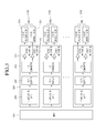
- FIG. 2 is a block diagram showing a configuration of a PLC control apparatus according to the embodiment.
- the PLC control apparatus 200 includes a user input unit 201, a control unit 203, a calculation unit 205, an interpolation unit 207, a conversion unit 209, and a channel unit 211.
- the user input unit 201 receives user's input to select an analog output channel.
- the channel may refer to a path to transmit a PLC output signal to an external device 10.
- the user may set at least one of a plurality of channels as a transmission path by using the user input unit 201.
- the control unit 203 controls a signal to be output to the external device 10 through the channel selected by the user.
- the control unit 203 may select at least one channel according to the user's input received in the user input unit 201. For instance, the control unit 203 may transmit a signal, which selects at least one of a plurality of channels, to a channel unit 211 to be described later.
- the control unit 203 may initialize the preset value. For instance, the control unit 203 may transmit an initialization command signal for the selected signal to the channel unit 211.
- control unit 203 can confirm the allowance of the digital-analog conversion in the selected channel. For instance, the control unit 203 may inquire the allowance of the digital-analog conversion in the selected channel to the channel unit 211.
- the control unit 203 may terminate the PLC output signal control after initializing the data. For instance, upon receiving the answer of prohibiting the digital-analog conversion in the selected channel from the channel unit 211, the control unit 211 may terminate the PLC output signal control.
- initialized data may refer to data, which are input for the PLC output signal control, or preset data, but the embodiment is not limited thereto.
- the control unit 203 may perform the PLC output signal control. For instance, upon receiving the answer of allowing the digital-analog conversion in the selected channel from the channel unit 211, the control unit 211 may continuously perform the PLC output signal control. The control unit 211 may transfer a PLC digital output signal to the calculation unit 205, which will be described later, for the PLC output signal control.
- the calculation unit 205 calculates a value of the PLC digital output signal.
- the PLC digital output signal may refer to a digital output signal which is actually transferred to the external device 10 from the PLC control apparatus 200.
- the calculation unit 205 can calculate the value of the PLC digital output signal according to the analog resolution.
- the calculation unit 205 may calculate the value of the PLC digital output signal in the range of 0 to 4000 when the analog resolution is 12 bits and may calculate the value of the PLC digital output signal in the range of 0 to 16000 when the analog resolution is 14 bits.
- the range of the PLC digital output signal may refer to the similarity between the digital output signal and the analog output signal.
- the similarity between the digital output signal and the analog output signal may become high as the range of the PLC digital output signal value is wide.
- the interpolation unit 207 interpolates the PLC digital output signal calculated in the calculation unit 205. After the interpolation has been performed by the interpolation unit 207, an edge of the PLC digital output signal may have an S-shape curve in the graph.
- the interpolation unit 207 may confirm the allowance of the interpolation in the selected channel. For instance, the interpolation unit 207 may inquire the allowance of the interpolation in the selected channel to the channel unit 211.
- the interpolation unit 207 may interpolate the calculated PLC digital output signal. For instance, upon receiving the answer of allowing the interpolation in the selected channel from the channel unit 211, the interpolation unit 207 may interpolate the PLC digital output signal.
- the interpolation unit 207 may interpolate the digital output signal by using a sigmoid function.
- the interpolation unit 207 may individually adjust the offset gain of the PLC digital output signal, which has been interpolated through the sigmoid function, by using a linear correction function.
- the interpolation unit 207 may interpolate the PLC digital output signal according to at least one of a predetermined interpolation frequency, a target value and a scan time.
- the interpolation frequency may be set according to the user's input, and the PLC digital output signal may be more smoothly interpolated as the interpolation frequency is increased.
- the conversion unit 209 converts the interpolated PLC digital output signal into the PLC analog output signal.
- the conversion unit 209 converts the PLC digital output signal, which has been interpolated in the interpolation unit 207, into the PLC analog output signal, the PLC analog output signal having the edge of the S-shape curve can be output.
- the PLC analog output signal converted by the conversion unit 209 may be amplified and then transferred to the channel unit 211.
- the channel unit 211 transfers the PLC analog output signal, which is transmitted from the conversion unit 209, to the external device 10.
- the PLC control apparatus 200 can transmit the PLC analog output signal, in which the S-shape interpolation has been completed, to the external device 10.
- FIG. 3 is a block diagram showing a configuration of the PLC output control apparatus according to the embodiment.
- the PLC output control apparatus may include a microprocessor unit (MPU) 301 and an analog output circuit 303.
- the PLC output control apparatus shown in FIG. 3 may be one embodiment of the PLC output control apparatus described above with reference to FIG. 2 .
- the PLC output control apparatus shown in FIG. 3 may be a part of the PLC or may be separated from the PLC, and the embodiment is not limited thereto.
- the MPU 301 may generate a digital signal to transfer the digital signal to the analog output circuit 303.
- the analog output circuit 303 includes an interpolation unit 305, a photo coupler 307, a DA converter 309, amplification units 311 and 313 and a channel 319.
- the analog output circuit 303 converts a digital signal received from the MPU 301 into an analog signal and outputs an analog voltage and an analog current through the channel 319 after the voltage amplification and the current amplification.
- the PLC transmits the analog voltage and the analog current to the external device to control the operation of the external device.
- the interpolation unit 305 can interpolate the digital signal.
- the digital signal is output in the form of a step function having a steep gradient. That is, in general, the digital signal has a waveform having the value that is abruptly changed from 0 to the target value or from the target value to 0 at the specific point.
- the interpolation unit 305 interpolates the digital signal such that the digital signal output can be gradually changed from 0 to the target value or from the target value to 0 within a predetermined time range, thereby smoothing the gradient of the digital signal.
- the photo coupler 307 can electrically insulate the MPU 301 from the analog output circuit 303.
- the digital signal generated from the MPU 301 can be transferred to the DA converter 309 after being insulated by the photo coupler 307.
- the DA converter 309 can convert the digital signal, which has been interpolated to have a smooth gradient, into the analog signal.
- the amplification units 311 and 313 amplify the intensity of the analog signal output from the DA converter 309 to the extent that the external device can be driven.
- the amplification units 311 and 313 may include a voltage amplifier and a voltage amplifier.
- the voltage amplifier 311 may include an OP-AMP for amplifying an analog voltage signal.
- the current amplifier 313 may include an OP-AMP for amplifying an analog current signal.
- An analog voltage signal 315 and an analog current signal 317 for driving the external device are output through one channel 319.
- the user can set the analog output channel 319 according to the external device. If the user sets a first channel CH1, the analog output circuit 303 may convert the digital signal into the analog signal only when the first channel CH1 allows the analog signal conversion.
- FIG. 4 is a flowchart showing a PLC output control method according to the embodiment.
- the channel 319 can be set according to the user's selection in order to convert the PLC digital output into the PLC analog output for driving the external device.
- the MPU 301 selects the analog output circuit 303 including the channel 319 set by the user (S401).
- the MPU 301 can initialize the preset value in order to input a new value to the selected analog output circuit 303.
- the MPU 301 may determine whether the digital-analog conversion is allowed in the analog output circuit 303 including the channel 319 (S403). If the digital-analog conversion is not allowed in the analog output circuit 303, the MPU 301 may initialize the preset data of the analog output circuit 303 and terminate the digital-analog conversion process (S405).
- the analog output circuit 303 may calculate a register setting value required for the digital-analog conversion of the DA converter 309 (S407).
- the analog output circuit 303 may calculate the digital output value to be output actually (S409).
- the analog output circuit 303 may calculate the digital output value in the range of 0 to 4000 when the analog resolution is 12 bits and may calculate the digital output value in the range of 0 to 16000 when the analog resolution is 14 bits.
- the analog output circuit 303 may determine whether the digital output interpolation is allowed in the selected channel 319 (S411). If the interpolation is not allowed in the channel 319, the digital output is transferred to the DA converter 309 through the photo coupler 307 (S415).
- the digital output is transferred to the interpolation unit 305 and the interpolation unit 305 interpolates the digital output (S413).
- the interpolation unit 305 can interpolate the PLC digital output in the form of an S-shape by executing the nonlinear interpolation algorithm and the linear interpolation algorithm.
- the S-shape interpolation refers to the interpolation to interpolate the output having a steep gradient in the form of a step function into the output having a smooth gradient.
- the sigmoid function may be utilized to execute the nonlinear interpolation algorithm, and the linear correction function may be utilized to execute the linear interpolation algorithm.
- the linear correction function is used to adjust the offset gain which is not implemented by the sigmoid function.
- the sigmoid application function is expressed as following equation 1.
- P 1 t 1 1 + e - 0.7 ⁇ 10 ⁇ t ⁇ - 5 ⁇ ⁇ ⁇ : interpolation frequency
- ⁇ target value
- t scan time (ms)
- Equation 1 is the sigmoid application function obtained by transforming the coefficient of the sigmoid function.
- the interpolation frequency ( ⁇ ) refers to the number of times for drawing straight lines to draw a graph approximate to a curve by using straight lines when the sigmoid application function is represented in the graph.
- the digital output approximate to the curve can be obtained as the interpolation frequency ( ⁇ ) is increased.
- the target value ( ⁇ ) refers to the final digital output value.
- the interpolation frequency ( ⁇ ) and the target value ( ⁇ ) may be set depending on the purpose of the user.
- the scan time (t) refers to the time to reach the target value from o.
- P1(t) refers to the digital output to which the nonlinear interpolation algorithm has been executed. Referring to Equation 1, the P1(t) does not output the target value ( ⁇ ), but is converged even if the scan time (t) is infinitely increased. Therefore, the interpolation unit 305 must use the linear correction function to output the target value ( ⁇ ).
- Equation 2 P2(t) refers to the digital output which is obtained by executing the linear interpolation algorithm with respect to the digital output P1(t) to which the nonlinear interpolation algorithm has been executed. Since Equation 2 is for the offset gain adjustment, it is expressed as a simple equation and the user may preset the threshold value. If the P1(t) is applied to Equation 2, the offset value can be output at the threshold value or less, and the target value ( ⁇ ) can be output at the value above the threshold value. As a result of the linear interpolation algorithm, the P2(t) can output the target value ( ⁇ ) when the scan time (t) has elapsed.
- the final digital output to which the interpolation algorithm has been executed or the digital output to which the interpolation algorithm is not executed is transferred to the DA converter 309 through the photo coupler 307 (S415).
- the DA converter 309 converts the digital output signal into the analog output signal (S417).
- the voltage amplifying unit 311 amplifies the converted analog output voltage such that the analog output voltage has the intensity sufficient for driving the external device and the current amplifying unit 313 amplifies the converted analog output current such that the analog output current has the intensity sufficient for driving the external device (S419).
- the analog output circuit 303 outputs the analog output voltage or current through the channel 319 so that the PLC can control the external device connected to the channel (S421).
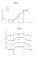
- FIG. 5 is a graph to explain an output according to the embodiment.
- the analog output P(t) is obtained by converting the digital output signal, to which the interpolation algorithm has been executed, to the analog signal.
- straight lines refer to the digital output signals to which the interpolation algorithm has been executed
- a curve line refers to the analog output signal.
- the target value of the analog output signal is ⁇ and t is the scan time required for the output value of the analog output signal to reach the target value from o. For instance, if the interpolation frequency ⁇ is 4, the analog output P(t) is ⁇ /8 at a point of t/4, ⁇ /2 at a point of t/2, 7 ⁇ /8 at a point of 3t/4, and ⁇ at a point of t.
- the graph of the analog output P(t) has the S-shape where first and fourth sections of the scan time have the smoother gradient and second and third sections of the scan time have the steeper gradient. If the analog output signal, to which the S-shape interpolation has been completed, is applied to the external device, the effect shown in FIG. 6 may be represented.
- FIG. 6 is a graph showing PLC response characteristics according to the embodiment.
- a digital output 601 transferred from the MPU 301 is in the form of a step function and the value of the digital output 601 is changed from 0 to 16000 at an output change point 609.
- a digital output 603 interpolated through the interpolation unit 305 is in the form of S-shape and the gradient of the digital output 603 is gradually changed from the output change point 609 so that the value of the digital output 603 reaches the initial value (0) or the target value (16000).
- an analog current output 605 obtained by converting the interpolated digital output 603 is also in the form of S-shape and the gradient is gradually changed from the output change point 609 so that the value of the analog current output 605 reaches the initial value (0) or the target value (20mA).
- the analog output circuit 303 according to the embodiment can control the external device to output the smooth response other than the transient response indicated by reference numeral 611, so that the control device having superior stability can be provided.
- the analog output circuit 303 according to the embodiment can gradually change the intensity of the voltage or current input into the external device, so that the external device can be prevented from being malfunctioned or broken.
Landscapes
- Physics & Mathematics (AREA)
- General Physics & Mathematics (AREA)
- Engineering & Computer Science (AREA)
- Automation & Control Theory (AREA)
- Programmable Controllers (AREA)
Abstract
Description
- The embodiment relates to an apparatus and a method for controlling an output signal of a programmable logic controller (PLC).
- Automatic equipment used in industrial fields consists of mechanical equipment including a relay. There is a difficulty to change the automatic equipment consisting of the mechanical equipment because internal circuits of the automatic equipment must be changed. In order to overcome such a difficulty, the PLC, which is a general control device, is used.
- The PLC converts a digital signal input by a user into an analog signal and transmits the analog signal to external devices to control the external devices.
-
FIG. 1 is a graph showing general PLC response characteristics. - Referring to
FIG. 1 , a value of a PLCdigital signal output 101 is abruptly changed at aspecific point 107. Thus, a value of a PLCanalog signal output 103, which is obtained by converting the PLCdigital signal output 101, is also abruptly changed at thespecific point 107. - Meanwhile, if the PLC
analog signal output 103 is transferred to an external device, aload response 105 of the external device may become atransient response 109 at thespecific point 107 at which the value of the PLCanalog signal output 103 is abruptly changed. The external device may malfunction or, in extreme cases, may be broken due to thetransient response 109. - The embodiment provides an apparatus and a method for controlling a PLC, capable of preventing a transient response of an external device by interpolating a PLC output signal to be supplied to the external device.
- A method of controlling a PLC digital output signal according to the embodiment includes receiving the PLC digital output signal; and interpolating a gradient of the PLC digital output signal by applying a nonlinear correction function to the received PLC digital output signal.
- An apparatus for controlling a PLC digital output signal according to the embodiment includes a calculation unit to calculate a value of a signal to be actually output, an interpolation unit to interpolate a signal by applying a nonlinear correction function, a conversion unit to convert a digital signal into an analog signal, and a control unit that controls the calculation unit such that the PLC digital output signal is calculated as an actual output value, controls the interpolation unit to apply the nonlinear correction function to the PLC digital output signal calculated in the calculation unit, and controls the conversion unit to convert the PLC digital output signal interpolated in the interpolation unit into a PLC analog output signal.
- According to the embodiment, it is possible to provide an apparatus and a method for controlling a PLC, capable of preventing a transient response of an external device by interpolating a PLC output signal to be supplied to the external device.
-
FIG. 1 is a graph showing general PLC response characteristics; -
FIG. 2 is a block diagram showing a configuration of a PLC control apparatus according to the embodiment; -
FIG. 3 is a block diagram showing a configuration of a PLC output control apparatus according to the embodiment; -
FIG. 4 is a flowchart showing a PLC output control method according to the embodiment; -
FIG. 5 is a graph to explain an output according to the embodiment; and -
FIG. 6 is a graph showing PLC response characteristics according to the embodiment. - Hereinafter, embodiments will be described in detail with reference to accompanying drawings.
-
FIG. 2 is a block diagram showing a configuration of a PLC control apparatus according to the embodiment. - Referring to
FIG. 2 , thePLC control apparatus 200 includes auser input unit 201, acontrol unit 203, acalculation unit 205, aninterpolation unit 207, aconversion unit 209, and achannel unit 211. - The
user input unit 201 receives user's input to select an analog output channel. - The channel may refer to a path to transmit a PLC output signal to an
external device 10. The user may set at least one of a plurality of channels as a transmission path by using theuser input unit 201. - The
control unit 203 controls a signal to be output to theexternal device 10 through the channel selected by the user. - The
control unit 203 may select at least one channel according to the user's input received in theuser input unit 201. For instance, thecontrol unit 203 may transmit a signal, which selects at least one of a plurality of channels, to achannel unit 211 to be described later. - At this time, if the selected channel has a preset value, the
control unit 203 may initialize the preset value. For instance, thecontrol unit 203 may transmit an initialization command signal for the selected signal to thechannel unit 211. - In addition, the
control unit 203 can confirm the allowance of the digital-analog conversion in the selected channel. For instance, thecontrol unit 203 may inquire the allowance of the digital-analog conversion in the selected channel to thechannel unit 211. - If the digital-analog conversion in the selected channel is prohibited, the
control unit 203 may terminate the PLC output signal control after initializing the data. For instance, upon receiving the answer of prohibiting the digital-analog conversion in the selected channel from thechannel unit 211, thecontrol unit 211 may terminate the PLC output signal control. At this time, initialized data may refer to data, which are input for the PLC output signal control, or preset data, but the embodiment is not limited thereto. - In contrast, if the digital-analog conversion in the selected channel is allowed, the
control unit 203 may perform the PLC output signal control. For instance, upon receiving the answer of allowing the digital-analog conversion in the selected channel from thechannel unit 211, thecontrol unit 211 may continuously perform the PLC output signal control. Thecontrol unit 211 may transfer a PLC digital output signal to thecalculation unit 205, which will be described later, for the PLC output signal control. - The
calculation unit 205 calculates a value of the PLC digital output signal. The PLC digital output signal may refer to a digital output signal which is actually transferred to theexternal device 10 from thePLC control apparatus 200. - The
calculation unit 205 can calculate the value of the PLC digital output signal according to the analog resolution. - For instance, the
calculation unit 205 may calculate the value of the PLC digital output signal in the range of 0 to 4000 when the analog resolution is 12 bits and may calculate the value of the PLC digital output signal in the range of 0 to 16000 when the analog resolution is 14 bits. - At this time, the range of the PLC digital output signal may refer to the similarity between the digital output signal and the analog output signal. For instance, the similarity between the digital output signal and the analog output signal may become high as the range of the PLC digital output signal value is wide.
- The
interpolation unit 207 interpolates the PLC digital output signal calculated in thecalculation unit 205. After the interpolation has been performed by theinterpolation unit 207, an edge of the PLC digital output signal may have an S-shape curve in the graph. - The
interpolation unit 207 may confirm the allowance of the interpolation in the selected channel. For instance, theinterpolation unit 207 may inquire the allowance of the interpolation in the selected channel to thechannel unit 211. - If the interpolation in the selected channel is allowed, the
interpolation unit 207 may interpolate the calculated PLC digital output signal. For instance, upon receiving the answer of allowing the interpolation in the selected channel from thechannel unit 211, theinterpolation unit 207 may interpolate the PLC digital output signal. - The
interpolation unit 207 may interpolate the digital output signal by using a sigmoid function. In addition, theinterpolation unit 207 may individually adjust the offset gain of the PLC digital output signal, which has been interpolated through the sigmoid function, by using a linear correction function. - In addition, the
interpolation unit 207 may interpolate the PLC digital output signal according to at least one of a predetermined interpolation frequency, a target value and a scan time. For instance, the interpolation frequency may be set according to the user's input, and the PLC digital output signal may be more smoothly interpolated as the interpolation frequency is increased. - The
conversion unit 209 converts the interpolated PLC digital output signal into the PLC analog output signal. - Since the
conversion unit 209 converts the PLC digital output signal, which has been interpolated in theinterpolation unit 207, into the PLC analog output signal, the PLC analog output signal having the edge of the S-shape curve can be output. The PLC analog output signal converted by theconversion unit 209 may be amplified and then transferred to thechannel unit 211. - The
channel unit 211 transfers the PLC analog output signal, which is transmitted from theconversion unit 209, to theexternal device 10. - Therefore, the
PLC control apparatus 200 can transmit the PLC analog output signal, in which the S-shape interpolation has been completed, to theexternal device 10. -
FIG. 3 is a block diagram showing a configuration of the PLC output control apparatus according to the embodiment. - Referring to
FIG. 3 , the PLC output control apparatus may include a microprocessor unit (MPU) 301 and ananalog output circuit 303. The PLC output control apparatus shown inFIG. 3 may be one embodiment of the PLC output control apparatus described above with reference toFIG. 2 . In addition, the PLC output control apparatus shown inFIG. 3 may be a part of the PLC or may be separated from the PLC, and the embodiment is not limited thereto. - The
MPU 301 may generate a digital signal to transfer the digital signal to theanalog output circuit 303. - The
analog output circuit 303 includes aninterpolation unit 305, aphoto coupler 307, aDA converter 309,amplification units channel 319. Theanalog output circuit 303 converts a digital signal received from theMPU 301 into an analog signal and outputs an analog voltage and an analog current through thechannel 319 after the voltage amplification and the current amplification. The PLC transmits the analog voltage and the analog current to the external device to control the operation of the external device. - The
interpolation unit 305 can interpolate the digital signal. The digital signal is output in the form of a step function having a steep gradient. That is, in general, the digital signal has a waveform having the value that is abruptly changed from 0 to the target value or from the target value to 0 at the specific point. Theinterpolation unit 305 interpolates the digital signal such that the digital signal output can be gradually changed from 0 to the target value or from the target value to 0 within a predetermined time range, thereby smoothing the gradient of the digital signal. - The
photo coupler 307 can electrically insulate theMPU 301 from theanalog output circuit 303. Thus, the digital signal generated from theMPU 301 can be transferred to theDA converter 309 after being insulated by thephoto coupler 307. - The
DA converter 309 can convert the digital signal, which has been interpolated to have a smooth gradient, into the analog signal. - The
amplification units DA converter 309 to the extent that the external device can be driven. Theamplification units voltage amplifier 311 may include an OP-AMP for amplifying an analog voltage signal. Thecurrent amplifier 313 may include an OP-AMP for amplifying an analog current signal. - An
analog voltage signal 315 and an analogcurrent signal 317 for driving the external device are output through onechannel 319. The user can set theanalog output channel 319 according to the external device. If the user sets a first channel CH1, theanalog output circuit 303 may convert the digital signal into the analog signal only when the first channel CH1 allows the analog signal conversion. -
FIG. 4 is a flowchart showing a PLC output control method according to the embodiment. - Referring to
FIG. 4 , thechannel 319 can be set according to the user's selection in order to convert the PLC digital output into the PLC analog output for driving the external device. TheMPU 301 selects theanalog output circuit 303 including thechannel 319 set by the user (S401). TheMPU 301 can initialize the preset value in order to input a new value to the selectedanalog output circuit 303. - The
MPU 301 may determine whether the digital-analog conversion is allowed in theanalog output circuit 303 including the channel 319 (S403). If the digital-analog conversion is not allowed in theanalog output circuit 303, theMPU 301 may initialize the preset data of theanalog output circuit 303 and terminate the digital-analog conversion process (S405). - If the digital-analog conversion is allowed in the
analog output circuit 303, theanalog output circuit 303 may calculate a register setting value required for the digital-analog conversion of the DA converter 309 (S407). - In addition, the
analog output circuit 303 may calculate the digital output value to be output actually (S409). Theanalog output circuit 303 may calculate the digital output value in the range of 0 to 4000 when the analog resolution is 12 bits and may calculate the digital output value in the range of 0 to 16000 when the analog resolution is 14 bits. - Then, the
analog output circuit 303 may determine whether the digital output interpolation is allowed in the selected channel 319 (S411). If the interpolation is not allowed in thechannel 319, the digital output is transferred to theDA converter 309 through the photo coupler 307 (S415). - If the interpolation is allowed in the
channel 319, the digital output is transferred to theinterpolation unit 305 and theinterpolation unit 305 interpolates the digital output (S413). Theinterpolation unit 305 can interpolate the PLC digital output in the form of an S-shape by executing the nonlinear interpolation algorithm and the linear interpolation algorithm. The S-shape interpolation refers to the interpolation to interpolate the output having a steep gradient in the form of a step function into the output having a smooth gradient. The sigmoid function may be utilized to execute the nonlinear interpolation algorithm, and the linear correction function may be utilized to execute the linear interpolation algorithm. The linear correction function is used to adjust the offset gain which is not implemented by the sigmoid function. - For instance, the sigmoid application function is expressed as following equation 1.

α : interpolation frequency
β : target value
t: scan time (ms) - Equation 1 is the sigmoid application function obtained by transforming the coefficient of the sigmoid function.
- The interpolation frequency (α) refers to the number of times for drawing straight lines to draw a graph approximate to a curve by using straight lines when the sigmoid application function is represented in the graph. The digital output approximate to the curve can be obtained as the interpolation frequency (α) is increased.
- The target value (β) refers to the final digital output value. The interpolation frequency (α) and the target value (β) may be set depending on the purpose of the user.
- The scan time (t) refers to the time to reach the target value from o.
- In Equation 1, P1(t) refers to the digital output to which the nonlinear interpolation algorithm has been executed. Referring to Equation 1, the P1(t) does not output the target value (β), but is converged even if the scan time (t) is infinitely increased. Therefore, the
interpolation unit 305 must use the linear correction function to output the target value (β). - For instance, the linear correction function is expressed as following
equation 2. -

- In
Equation 2, P2(t) refers to the digital output which is obtained by executing the linear interpolation algorithm with respect to the digital output P1(t) to which the nonlinear interpolation algorithm has been executed. SinceEquation 2 is for the offset gain adjustment, it is expressed as a simple equation and the user may preset the threshold value. If the P1(t) is applied toEquation 2, the offset value can be output at the threshold value or less, and the target value (β) can be output at the value above the threshold value. As a result of the linear interpolation algorithm, the P2(t) can output the target value (β) when the scan time (t) has elapsed. - Then, the final digital output to which the interpolation algorithm has been executed or the digital output to which the interpolation algorithm is not executed is transferred to the
DA converter 309 through the photo coupler 307 (S415). - The
DA converter 309 converts the digital output signal into the analog output signal (S417). - The
voltage amplifying unit 311 amplifies the converted analog output voltage such that the analog output voltage has the intensity sufficient for driving the external device and thecurrent amplifying unit 313 amplifies the converted analog output current such that the analog output current has the intensity sufficient for driving the external device (S419). - Then, the
analog output circuit 303 outputs the analog output voltage or current through thechannel 319 so that the PLC can control the external device connected to the channel (S421). -
FIG. 5 is a graph to explain an output according to the embodiment. - Referring to
FIG. 5 , the analog output P(t) is obtained by converting the digital output signal, to which the interpolation algorithm has been executed, to the analog signal. InFIG. 5 , straight lines refer to the digital output signals to which the interpolation algorithm has been executed, and a curve line refers to the analog output signal. The target value of the analog output signal is β and t is the scan time required for the output value of the analog output signal to reach the target value from o. For instance, if the interpolation frequency α is 4, the analog output P(t) is β/8 at a point of t/4, β/2 at a point of t/2, 7β/8 at a point of 3t/4, and β at a point of t. That is, if the scan time is divided into four, the graph of the analog output P(t) has the S-shape where first and fourth sections of the scan time have the smoother gradient and second and third sections of the scan time have the steeper gradient. If the analog output signal, to which the S-shape interpolation has been completed, is applied to the external device, the effect shown inFIG. 6 may be represented. -
FIG. 6 is a graph showing PLC response characteristics according to the embodiment. - Referring to
FIG. 6 , adigital output 601 transferred from theMPU 301 is in the form of a step function and the value of thedigital output 601 is changed from 0 to 16000 at anoutput change point 609. However, adigital output 603 interpolated through theinterpolation unit 305 is in the form of S-shape and the gradient of thedigital output 603 is gradually changed from theoutput change point 609 so that the value of thedigital output 603 reaches the initial value (0) or the target value (16000). In addition, an analogcurrent output 605 obtained by converting the interpolateddigital output 603 is also in the form of S-shape and the gradient is gradually changed from theoutput change point 609 so that the value of the analogcurrent output 605 reaches the initial value (0) or the target value (20mA). - As a result, a load that receives the
analog output 605 can output the response in the form of S. Theanalog output circuit 303 according to the embodiment can control the external device to output the smooth response other than the transient response indicated byreference numeral 611, so that the control device having superior stability can be provided. In addition, theanalog output circuit 303 according to the embodiment can gradually change the intensity of the voltage or current input into the external device, so that the external device can be prevented from being malfunctioned or broken. - Although embodiments have been described with reference to a number of illustrative embodiments thereof, it should be understood that numerous other modifications and embodiments can be devised by those skilled in the art that will fall within the spirit and scope of the principles of this disclosure.
- Therefore, the embodiments do not intend to limit the technical features of the disclosure but intend to explain the technical features of the disclosure and the technical features of the disclosure may not limited by the above embodiments.
Claims (10)
- A method of controlling a PLC digital output signal, the method comprising:receiving the PLC digital output signal; andinterpolating a gradient of the PLC digital output signal by applying a nonlinear correction function to the received PLC digital output signal.
- The method of claim 1, wherein the interpolating of the gradient comprises interpolating the gradient by setting at least one of an interpolation frequency, a target value and a scan time.
- The method of claim 1, wherein the nonlinear correction function comprises a sigmoid function.
- The method of claim 1, further comprising:selecting at least one channel according to a user input, wherein the interpolating of the gradient is performed only when a digital-analog conversion and an interpolation are allowed in the selected channel.
- The method of claim 1, further comprising:performing an interpolation by applying a linear correction function to adjust an offset gain of the PLC digital output signal to which the nonlinear correction function is applied.
- An apparatus for controlling a PLC digital output signal, the apparatus comprising:a calculation unit to calculate a value of a signal to be actually output;an interpolation unit to interpolate a signal by applying a nonlinear correction function;a conversion unit to convert a digital signal into an analog signal; anda control unit that controls the calculation unit such that the PLC digital output signal is calculated as an actual output value, controls the interpolation unit to apply the nonlinear correction function to the PLC digital output signal calculated in the calculation unit, and controls the conversion unit to convert the PLC digital output signal interpolated in the interpolation unit into a PLC analog output signal.
- The apparatus of claim 6, wherein the interpolation unit interpolates the PLC digital output signal calculated in the calculation unit by setting at least one of an interpolation frequency, a target value and a scan time.
- The apparatus of claim 6, wherein the nonlinear correction function used in the interpolation unit comprises a sigmoid function.
- The apparatus of claim 6, further comprising:a channel unit to transmit the PLC digital output signal to an external device; anda user input unit to receive a user input for selecting at least one channel,wherein the control unit selects at least one channel according to the user input, determines whether a digital-analog conversion and an interpolation are allowed in the selected channel, and controls the calculation unit, the interpolation unit and the conversion unit only when the digital-analog conversion and the interpolation are allowed in the selected channel.
- The apparatus of claim 6, wherein the interpolation unit performs an interpolation by applying a linear correction function to adjust an offset gain of the PLC digital output signal to which the nonlinear correction function is applied.
Applications Claiming Priority (1)
| Application Number | Priority Date | Filing Date | Title |
|---|---|---|---|
| KR1020120061126A KR101354767B1 (en) | 2012-06-07 | 2012-06-07 | Apparatus and method for controlling output |
Publications (3)
| Publication Number | Publication Date |
|---|---|
| EP2672350A2 true EP2672350A2 (en) | 2013-12-11 |
| EP2672350A3 EP2672350A3 (en) | 2017-01-18 |
| EP2672350B1 EP2672350B1 (en) | 2021-03-03 |
Family
ID=48193120
Family Applications (1)
| Application Number | Title | Priority Date | Filing Date |
|---|---|---|---|
| EP13165278.6A Active EP2672350B1 (en) | 2012-06-07 | 2013-04-25 | Apparatus and method for controlling a programmable logic controller |
Country Status (6)
| Country | Link |
|---|---|
| US (1) | US9488972B2 (en) |
| EP (1) | EP2672350B1 (en) |
| JP (1) | JP5763706B2 (en) |
| KR (1) | KR101354767B1 (en) |
| CN (1) | CN103488115B (en) |
| ES (1) | ES2869188T3 (en) |
Families Citing this family (5)
| Publication number | Priority date | Publication date | Assignee | Title |
|---|---|---|---|---|
| CN103984279B (en) * | 2014-04-28 | 2016-08-31 | 南京工程学院 | Mixed signal experiment module based on PLC |
| JP6081967B2 (en) * | 2014-07-28 | 2017-02-15 | ファナック株式会社 | Output module with output common on / off function |
| CN104375454B (en) * | 2014-11-10 | 2018-07-03 | 深圳市合信自动化技术有限公司 | A kind of multichannel PID outgoing managements method, apparatus and PLC module |
| CN108351629B (en) | 2015-11-05 | 2022-03-18 | 三菱电机株式会社 | Functional unit and control device |
| CN107826667A (en) * | 2017-12-22 | 2018-03-23 | 大连佳林设备制造有限公司 | Automatic feeder control system that diameter is adjustable |
Family Cites Families (13)
| Publication number | Priority date | Publication date | Assignee | Title |
|---|---|---|---|---|
| JPS588304A (en) | 1981-07-07 | 1983-01-18 | Toshiba Corp | Analog signal output method |
| US5075880A (en) * | 1988-11-08 | 1991-12-24 | Wadia Digital Corporation | Method and apparatus for time domain interpolation of digital audio signals |
| US5087914A (en) * | 1990-08-22 | 1992-02-11 | Crystal Semiconductor Corp. | DC calibration system for a digital-to-analog converter |
| JP2914100B2 (en) | 1993-06-30 | 1999-06-28 | 三菱電機株式会社 | Analog signal processor for programmable controller |
| US5764546A (en) * | 1996-11-27 | 1998-06-09 | National Instruments Corporation | DAQ configuration system and method for configuring channels in a data acquisition device |
| US6978386B2 (en) * | 2000-12-28 | 2005-12-20 | Ge Fanuc Automation North America, Inc. | Method and apparatus for regulating current for programmable logic controllers |
| US7023580B2 (en) * | 2001-04-20 | 2006-04-04 | Agilent Technologies, Inc. | System and method for digital image tone mapping using an adaptive sigmoidal function based on perceptual preference guidelines |
| US7774079B2 (en) * | 2005-10-03 | 2010-08-10 | Sigmatel, Inc. | Method and system for receiving and decoding audio signals |
| KR100943068B1 (en) * | 2008-02-29 | 2010-02-18 | 전남대학교산학협력단 | Error Restoration Method Using Curve Interpolation |
| JP5324562B2 (en) * | 2008-06-16 | 2013-10-23 | パナソニック株式会社 | Reception device, integrated circuit, digital television receiver, reception method, and reception program |
| TWI378649B (en) * | 2009-05-26 | 2012-12-01 | Univ Nat Taiwan | Interpolation dac, non-linear interpolation circuit and interpolation current generating circuit thereof |
| CN102075469B (en) * | 2010-12-06 | 2013-01-02 | 北京邮电大学 | Estimation method for signal delay time of digital pre-distortion system |
| CN102279588B (en) * | 2010-12-15 | 2014-07-02 | 深圳众为兴技术股份有限公司 | Multi-axis full-closed loop motion control interpolator |
-
2012
- 2012-06-07 KR KR1020120061126A patent/KR101354767B1/en active Active
-
2013
- 2013-04-23 US US13/868,949 patent/US9488972B2/en active Active
- 2013-04-25 ES ES13165278T patent/ES2869188T3/en active Active
- 2013-04-25 EP EP13165278.6A patent/EP2672350B1/en active Active
- 2013-05-23 JP JP2013108816A patent/JP5763706B2/en not_active Expired - Fee Related
- 2013-06-07 CN CN201310226574.6A patent/CN103488115B/en active Active
Non-Patent Citations (1)
| Title |
|---|
| None |
Also Published As
| Publication number | Publication date |
|---|---|
| JP5763706B2 (en) | 2015-08-12 |
| KR101354767B1 (en) | 2014-01-23 |
| JP2013254487A (en) | 2013-12-19 |
| US20130331955A1 (en) | 2013-12-12 |
| US9488972B2 (en) | 2016-11-08 |
| ES2869188T3 (en) | 2021-10-25 |
| CN103488115A (en) | 2014-01-01 |
| KR20130137476A (en) | 2013-12-17 |
| EP2672350A3 (en) | 2017-01-18 |
| EP2672350B1 (en) | 2021-03-03 |
| CN103488115B (en) | 2016-01-20 |
Similar Documents
| Publication | Publication Date | Title |
|---|---|---|
| EP2672350B1 (en) | Apparatus and method for controlling a programmable logic controller | |
| EP2926452B1 (en) | Linearization circuits and methods for multilevel power amplifier systems | |
| CN100559703C (en) | Timing controller and timing control method | |
| US10164577B2 (en) | Linearization circuits and methods for multilevel power amplifier systems | |
| WO2018078511A3 (en) | Power converter with predictive pulse width modulator | |
| KR20150080589A (en) | Rf pulse edge shaping | |
| KR20090081086A (en) | Digital line distortion device and method for sharing feedback path in multi-antenna wireless communication system | |
| EP3211778A3 (en) | Dc-dc converter and display apparatus having the same | |
| CN108028632A (en) | Communication equipment with antenna damping compensation | |
| CN1988373A (en) | Device and method for controlling a voltage control signal | |
| KR20110103628A (en) | Digital Predistortion Apparatus and Method for Improving Performance Using Peak Level Expansion | |
| US20130215995A1 (en) | Apparatus and method for amplifying a signal from a transmitter | |
| EP4534376A3 (en) | Apparatus and method for controlling vehicle movement | |
| WO2008093665A1 (en) | Power voltage forming device and polar modulation transmission device | |
| EP1808959A1 (en) | Timing adjusting method and timing adjusting apparatus | |
| JP2017184073A (en) | Power amplifier and control method thereof | |
| US9473334B2 (en) | Wireless transmission device | |
| CN110505174B (en) | Modulation depth adjusting device and road side unit | |
| JP4899172B2 (en) | Pulse mode amplifier two peak power level control method and apparatus | |
| JP4527463B2 (en) | Automatic pulse waveform shaping method | |
| CN105282466B (en) | Signal processing system and signal processing method matched with variable gain amplifier | |
| CN111384849B (en) | Circuit structure and method for realizing dead time self-adaption function of D-type power amplifier | |
| US20170141745A1 (en) | Energy Supply Unit For A Traveling Wave Tube | |
| KR20070069638A (en) | Analog input module | |
| TWI705672B (en) | Orthogonal frequency division multiplex line driver system |
Legal Events
| Date | Code | Title | Description |
|---|---|---|---|
| PUAI | Public reference made under article 153(3) epc to a published international application that has entered the european phase |
Free format text: ORIGINAL CODE: 0009012 |
|
| AK | Designated contracting states |
Kind code of ref document: A2 Designated state(s): AL AT BE BG CH CY CZ DE DK EE ES FI FR GB GR HR HU IE IS IT LI LT LU LV MC MK MT NL NO PL PT RO RS SE SI SK SM TR |
|
| AX | Request for extension of the european patent |
Extension state: BA ME |
|
| PUAL | Search report despatched |
Free format text: ORIGINAL CODE: 0009013 |
|
| AK | Designated contracting states |
Kind code of ref document: A3 Designated state(s): AL AT BE BG CH CY CZ DE DK EE ES FI FR GB GR HR HU IE IS IT LI LT LU LV MC MK MT NL NO PL PT RO RS SE SI SK SM TR |
|
| AX | Request for extension of the european patent |
Extension state: BA ME |
|
| RIC1 | Information provided on ipc code assigned before grant |
Ipc: G05B 19/05 20060101AFI20161209BHEP |
|
| STAA | Information on the status of an ep patent application or granted ep patent |
Free format text: STATUS: REQUEST FOR EXAMINATION WAS MADE |
|
| 17P | Request for examination filed |
Effective date: 20170717 |
|
| RBV | Designated contracting states (corrected) |
Designated state(s): AL AT BE BG CH CY CZ DE DK EE ES FI FR GB GR HR HU IE IS IT LI LT LU LV MC MK MT NL NO PL PT RO RS SE SI SK SM TR |
|
| STAA | Information on the status of an ep patent application or granted ep patent |
Free format text: STATUS: EXAMINATION IS IN PROGRESS |
|
| 17Q | First examination report despatched |
Effective date: 20190107 |
|
| GRAP | Despatch of communication of intention to grant a patent |
Free format text: ORIGINAL CODE: EPIDOSNIGR1 |
|
| STAA | Information on the status of an ep patent application or granted ep patent |
Free format text: STATUS: GRANT OF PATENT IS INTENDED |
|
| INTG | Intention to grant announced |
Effective date: 20201118 |
|
| GRAS | Grant fee paid |
Free format text: ORIGINAL CODE: EPIDOSNIGR3 |
|
| GRAA | (expected) grant |
Free format text: ORIGINAL CODE: 0009210 |
|
| STAA | Information on the status of an ep patent application or granted ep patent |
Free format text: STATUS: THE PATENT HAS BEEN GRANTED |
|
| AK | Designated contracting states |
Kind code of ref document: B1 Designated state(s): AL AT BE BG CH CY CZ DE DK EE ES FI FR GB GR HR HU IE IS IT LI LT LU LV MC MK MT NL NO PL PT RO RS SE SI SK SM TR |
|
| REG | Reference to a national code |
Ref country code: GB Ref legal event code: FG4D |
|
| REG | Reference to a national code |
Ref country code: AT Ref legal event code: REF Ref document number: 1367899 Country of ref document: AT Kind code of ref document: T Effective date: 20210315 Ref country code: CH Ref legal event code: EP |
|
| REG | Reference to a national code |
Ref country code: DE Ref legal event code: R096 Ref document number: 602013075980 Country of ref document: DE |
|
| REG | Reference to a national code |
Ref country code: IE Ref legal event code: FG4D |
|
| REG | Reference to a national code |
Ref country code: LT Ref legal event code: MG9D |
|
| PG25 | Lapsed in a contracting state [announced via postgrant information from national office to epo] |
Ref country code: FI Free format text: LAPSE BECAUSE OF FAILURE TO SUBMIT A TRANSLATION OF THE DESCRIPTION OR TO PAY THE FEE WITHIN THE PRESCRIBED TIME-LIMIT Effective date: 20210303 Ref country code: GR Free format text: LAPSE BECAUSE OF FAILURE TO SUBMIT A TRANSLATION OF THE DESCRIPTION OR TO PAY THE FEE WITHIN THE PRESCRIBED TIME-LIMIT Effective date: 20210604 Ref country code: HR Free format text: LAPSE BECAUSE OF FAILURE TO SUBMIT A TRANSLATION OF THE DESCRIPTION OR TO PAY THE FEE WITHIN THE PRESCRIBED TIME-LIMIT Effective date: 20210303 Ref country code: LT Free format text: LAPSE BECAUSE OF FAILURE TO SUBMIT A TRANSLATION OF THE DESCRIPTION OR TO PAY THE FEE WITHIN THE PRESCRIBED TIME-LIMIT Effective date: 20210303 Ref country code: BG Free format text: LAPSE BECAUSE OF FAILURE TO SUBMIT A TRANSLATION OF THE DESCRIPTION OR TO PAY THE FEE WITHIN THE PRESCRIBED TIME-LIMIT Effective date: 20210603 Ref country code: NO Free format text: LAPSE BECAUSE OF FAILURE TO SUBMIT A TRANSLATION OF THE DESCRIPTION OR TO PAY THE FEE WITHIN THE PRESCRIBED TIME-LIMIT Effective date: 20210603 |
|
| REG | Reference to a national code |
Ref country code: NL Ref legal event code: MP Effective date: 20210303 |
|
| REG | Reference to a national code |
Ref country code: AT Ref legal event code: MK05 Ref document number: 1367899 Country of ref document: AT Kind code of ref document: T Effective date: 20210303 |
|
| PG25 | Lapsed in a contracting state [announced via postgrant information from national office to epo] |
Ref country code: SE Free format text: LAPSE BECAUSE OF FAILURE TO SUBMIT A TRANSLATION OF THE DESCRIPTION OR TO PAY THE FEE WITHIN THE PRESCRIBED TIME-LIMIT Effective date: 20210303 Ref country code: PL Free format text: LAPSE BECAUSE OF FAILURE TO SUBMIT A TRANSLATION OF THE DESCRIPTION OR TO PAY THE FEE WITHIN THE PRESCRIBED TIME-LIMIT Effective date: 20210303 Ref country code: LV Free format text: LAPSE BECAUSE OF FAILURE TO SUBMIT A TRANSLATION OF THE DESCRIPTION OR TO PAY THE FEE WITHIN THE PRESCRIBED TIME-LIMIT Effective date: 20210303 Ref country code: RS Free format text: LAPSE BECAUSE OF FAILURE TO SUBMIT A TRANSLATION OF THE DESCRIPTION OR TO PAY THE FEE WITHIN THE PRESCRIBED TIME-LIMIT Effective date: 20210303 |
|
| PG25 | Lapsed in a contracting state [announced via postgrant information from national office to epo] |
Ref country code: NL Free format text: LAPSE BECAUSE OF FAILURE TO SUBMIT A TRANSLATION OF THE DESCRIPTION OR TO PAY THE FEE WITHIN THE PRESCRIBED TIME-LIMIT Effective date: 20210303 |
|
| REG | Reference to a national code |
Ref country code: ES Ref legal event code: FG2A Ref document number: 2869188 Country of ref document: ES Kind code of ref document: T3 Effective date: 20211025 |
|
| PG25 | Lapsed in a contracting state [announced via postgrant information from national office to epo] |
Ref country code: CZ Free format text: LAPSE BECAUSE OF FAILURE TO SUBMIT A TRANSLATION OF THE DESCRIPTION OR TO PAY THE FEE WITHIN THE PRESCRIBED TIME-LIMIT Effective date: 20210303 Ref country code: EE Free format text: LAPSE BECAUSE OF FAILURE TO SUBMIT A TRANSLATION OF THE DESCRIPTION OR TO PAY THE FEE WITHIN THE PRESCRIBED TIME-LIMIT Effective date: 20210303 Ref country code: SM Free format text: LAPSE BECAUSE OF FAILURE TO SUBMIT A TRANSLATION OF THE DESCRIPTION OR TO PAY THE FEE WITHIN THE PRESCRIBED TIME-LIMIT Effective date: 20210303 Ref country code: AT Free format text: LAPSE BECAUSE OF FAILURE TO SUBMIT A TRANSLATION OF THE DESCRIPTION OR TO PAY THE FEE WITHIN THE PRESCRIBED TIME-LIMIT Effective date: 20210303 |
|
| PG25 | Lapsed in a contracting state [announced via postgrant information from national office to epo] |
Ref country code: IS Free format text: LAPSE BECAUSE OF FAILURE TO SUBMIT A TRANSLATION OF THE DESCRIPTION OR TO PAY THE FEE WITHIN THE PRESCRIBED TIME-LIMIT Effective date: 20210703 Ref country code: RO Free format text: LAPSE BECAUSE OF FAILURE TO SUBMIT A TRANSLATION OF THE DESCRIPTION OR TO PAY THE FEE WITHIN THE PRESCRIBED TIME-LIMIT Effective date: 20210303 Ref country code: SK Free format text: LAPSE BECAUSE OF FAILURE TO SUBMIT A TRANSLATION OF THE DESCRIPTION OR TO PAY THE FEE WITHIN THE PRESCRIBED TIME-LIMIT Effective date: 20210303 Ref country code: PT Free format text: LAPSE BECAUSE OF FAILURE TO SUBMIT A TRANSLATION OF THE DESCRIPTION OR TO PAY THE FEE WITHIN THE PRESCRIBED TIME-LIMIT Effective date: 20210705 |
|
| REG | Reference to a national code |
Ref country code: DE Ref legal event code: R097 Ref document number: 602013075980 Country of ref document: DE |
|
| PG25 | Lapsed in a contracting state [announced via postgrant information from national office to epo] |
Ref country code: LU Free format text: LAPSE BECAUSE OF NON-PAYMENT OF DUE FEES Effective date: 20210425 |
|
| PLBE | No opposition filed within time limit |
Free format text: ORIGINAL CODE: 0009261 |
|
| STAA | Information on the status of an ep patent application or granted ep patent |
Free format text: STATUS: NO OPPOSITION FILED WITHIN TIME LIMIT |
|
| REG | Reference to a national code |
Ref country code: BE Ref legal event code: MM Effective date: 20210430 |
|
| PG25 | Lapsed in a contracting state [announced via postgrant information from national office to epo] |
Ref country code: DK Free format text: LAPSE BECAUSE OF FAILURE TO SUBMIT A TRANSLATION OF THE DESCRIPTION OR TO PAY THE FEE WITHIN THE PRESCRIBED TIME-LIMIT Effective date: 20210303 Ref country code: MC Free format text: LAPSE BECAUSE OF FAILURE TO SUBMIT A TRANSLATION OF THE DESCRIPTION OR TO PAY THE FEE WITHIN THE PRESCRIBED TIME-LIMIT Effective date: 20210303 Ref country code: LI Free format text: LAPSE BECAUSE OF NON-PAYMENT OF DUE FEES Effective date: 20210430 Ref country code: CH Free format text: LAPSE BECAUSE OF NON-PAYMENT OF DUE FEES Effective date: 20210430 Ref country code: AL Free format text: LAPSE BECAUSE OF FAILURE TO SUBMIT A TRANSLATION OF THE DESCRIPTION OR TO PAY THE FEE WITHIN THE PRESCRIBED TIME-LIMIT Effective date: 20210303 |
|
| 26N | No opposition filed |
Effective date: 20211206 |
|
| PG25 | Lapsed in a contracting state [announced via postgrant information from national office to epo] |
Ref country code: SI Free format text: LAPSE BECAUSE OF FAILURE TO SUBMIT A TRANSLATION OF THE DESCRIPTION OR TO PAY THE FEE WITHIN THE PRESCRIBED TIME-LIMIT Effective date: 20210303 |
|
| PG25 | Lapsed in a contracting state [announced via postgrant information from national office to epo] |
Ref country code: IE Free format text: LAPSE BECAUSE OF NON-PAYMENT OF DUE FEES Effective date: 20210425 |
|
| PGFP | Annual fee paid to national office [announced via postgrant information from national office to epo] |
Ref country code: GB Payment date: 20220307 Year of fee payment: 10 |
|
| PG25 | Lapsed in a contracting state [announced via postgrant information from national office to epo] |
Ref country code: IS Free format text: LAPSE BECAUSE OF FAILURE TO SUBMIT A TRANSLATION OF THE DESCRIPTION OR TO PAY THE FEE WITHIN THE PRESCRIBED TIME-LIMIT Effective date: 20210703 |
|
| PG25 | Lapsed in a contracting state [announced via postgrant information from national office to epo] |
Ref country code: BE Free format text: LAPSE BECAUSE OF NON-PAYMENT OF DUE FEES Effective date: 20210430 |
|
| PGFP | Annual fee paid to national office [announced via postgrant information from national office to epo] |
Ref country code: ES Payment date: 20220509 Year of fee payment: 10 |
|
| PG25 | Lapsed in a contracting state [announced via postgrant information from national office to epo] |
Ref country code: HU Free format text: LAPSE BECAUSE OF FAILURE TO SUBMIT A TRANSLATION OF THE DESCRIPTION OR TO PAY THE FEE WITHIN THE PRESCRIBED TIME-LIMIT; INVALID AB INITIO Effective date: 20130425 |
|
| PG25 | Lapsed in a contracting state [announced via postgrant information from national office to epo] |
Ref country code: CY Free format text: LAPSE BECAUSE OF FAILURE TO SUBMIT A TRANSLATION OF THE DESCRIPTION OR TO PAY THE FEE WITHIN THE PRESCRIBED TIME-LIMIT Effective date: 20210303 |
|
| P01 | Opt-out of the competence of the unified patent court (upc) registered |
Effective date: 20230625 |
|
| GBPC | Gb: european patent ceased through non-payment of renewal fee |
Effective date: 20230425 |
|
| PG25 | Lapsed in a contracting state [announced via postgrant information from national office to epo] |
Ref country code: GB Free format text: LAPSE BECAUSE OF NON-PAYMENT OF DUE FEES Effective date: 20230425 |
|
| PG25 | Lapsed in a contracting state [announced via postgrant information from national office to epo] |
Ref country code: GB Free format text: LAPSE BECAUSE OF NON-PAYMENT OF DUE FEES Effective date: 20230425 |
|
| PG25 | Lapsed in a contracting state [announced via postgrant information from national office to epo] |
Ref country code: MK Free format text: LAPSE BECAUSE OF FAILURE TO SUBMIT A TRANSLATION OF THE DESCRIPTION OR TO PAY THE FEE WITHIN THE PRESCRIBED TIME-LIMIT Effective date: 20210303 |
|
| REG | Reference to a national code |
Ref country code: ES Ref legal event code: FD2A Effective date: 20240606 |
|
| PG25 | Lapsed in a contracting state [announced via postgrant information from national office to epo] |
Ref country code: ES Free format text: LAPSE BECAUSE OF NON-PAYMENT OF DUE FEES Effective date: 20230426 |
|
| PG25 | Lapsed in a contracting state [announced via postgrant information from national office to epo] |
Ref country code: ES Free format text: LAPSE BECAUSE OF NON-PAYMENT OF DUE FEES Effective date: 20230426 |
|
| PG25 | Lapsed in a contracting state [announced via postgrant information from national office to epo] |
Ref country code: MT Free format text: LAPSE BECAUSE OF FAILURE TO SUBMIT A TRANSLATION OF THE DESCRIPTION OR TO PAY THE FEE WITHIN THE PRESCRIBED TIME-LIMIT Effective date: 20210303 |
|
| PGFP | Annual fee paid to national office [announced via postgrant information from national office to epo] |
Ref country code: DE Payment date: 20250305 Year of fee payment: 13 |
|
| PG25 | Lapsed in a contracting state [announced via postgrant information from national office to epo] |
Ref country code: TR Free format text: LAPSE BECAUSE OF FAILURE TO SUBMIT A TRANSLATION OF THE DESCRIPTION OR TO PAY THE FEE WITHIN THE PRESCRIBED TIME-LIMIT Effective date: 20210303 |
|
| PGFP | Annual fee paid to national office [announced via postgrant information from national office to epo] |
Ref country code: IT Payment date: 20260306 Year of fee payment: 14 |
|
| PGFP | Annual fee paid to national office [announced via postgrant information from national office to epo] |
Ref country code: FR Payment date: 20260309 Year of fee payment: 14 |