EP2672076A2 - Method for Shutting Down a Generator to Prepare the Generator for Restart - Google Patents
Method for Shutting Down a Generator to Prepare the Generator for Restart Download PDFInfo
- Publication number
- EP2672076A2 EP2672076A2 EP13170618.6A EP13170618A EP2672076A2 EP 2672076 A2 EP2672076 A2 EP 2672076A2 EP 13170618 A EP13170618 A EP 13170618A EP 2672076 A2 EP2672076 A2 EP 2672076A2
- Authority
- EP
- European Patent Office
- Prior art keywords
- generator
- fuel
- purge gas
- gas turbine
- fuel system
- Prior art date
- Legal status (The legal status is an assumption and is not a legal conclusion. Google has not performed a legal analysis and makes no representation as to the accuracy of the status listed.)
- Withdrawn
Links
- 238000000034 method Methods 0.000 title claims abstract description 30
- 239000000446 fuel Substances 0.000 claims abstract description 126
- 238000010926 purge Methods 0.000 claims abstract description 94
- 238000002485 combustion reaction Methods 0.000 claims abstract description 56
- 239000007789 gas Substances 0.000 claims description 156
- 230000000977 initiatory effect Effects 0.000 claims description 13
- 238000012360 testing method Methods 0.000 claims description 13
- 238000002955 isolation Methods 0.000 claims description 10
- 238000007865 diluting Methods 0.000 claims description 7
- 238000010408 sweeping Methods 0.000 claims description 7
- 230000004044 response Effects 0.000 claims description 6
- 239000003570 air Substances 0.000 description 19
- 101100100125 Mus musculus Traip gene Proteins 0.000 description 5
- IJGRMHOSHXDMSA-UHFFFAOYSA-N Atomic nitrogen Chemical compound N#N IJGRMHOSHXDMSA-UHFFFAOYSA-N 0.000 description 4
- 238000011084 recovery Methods 0.000 description 3
- 238000013022 venting Methods 0.000 description 3
- 230000006835 compression Effects 0.000 description 2
- 238000007906 compression Methods 0.000 description 2
- 238000006073 displacement reaction Methods 0.000 description 2
- 238000012806 monitoring device Methods 0.000 description 2
- 238000012544 monitoring process Methods 0.000 description 2
- 229910052757 nitrogen Inorganic materials 0.000 description 2
- 230000004075 alteration Effects 0.000 description 1
- 239000012080 ambient air Substances 0.000 description 1
- 230000015572 biosynthetic process Effects 0.000 description 1
- 238000004891 communication Methods 0.000 description 1
- 230000005611 electricity Effects 0.000 description 1
- 238000001914 filtration Methods 0.000 description 1
- 239000012530 fluid Substances 0.000 description 1
- 239000010763 heavy fuel oil Substances 0.000 description 1
- 238000005259 measurement Methods 0.000 description 1
- 239000000203 mixture Substances 0.000 description 1
- 238000012545 processing Methods 0.000 description 1
- 238000006467 substitution reaction Methods 0.000 description 1
- 238000011144 upstream manufacturing Methods 0.000 description 1
Images

Classifications
-
- F—MECHANICAL ENGINEERING; LIGHTING; HEATING; WEAPONS; BLASTING
- F01—MACHINES OR ENGINES IN GENERAL; ENGINE PLANTS IN GENERAL; STEAM ENGINES
- F01D—NON-POSITIVE DISPLACEMENT MACHINES OR ENGINES, e.g. STEAM TURBINES
- F01D21/00—Shutting-down of machines or engines, e.g. in emergency; Regulating, controlling, or safety means not otherwise provided for
-
- F—MECHANICAL ENGINEERING; LIGHTING; HEATING; WEAPONS; BLASTING
- F01—MACHINES OR ENGINES IN GENERAL; ENGINE PLANTS IN GENERAL; STEAM ENGINES
- F01D—NON-POSITIVE DISPLACEMENT MACHINES OR ENGINES, e.g. STEAM TURBINES
- F01D25/00—Component parts, details, or accessories, not provided for in, or of interest apart from, other groups
- F01D25/002—Cleaning of turbomachines
-
- F—MECHANICAL ENGINEERING; LIGHTING; HEATING; WEAPONS; BLASTING
- F02—COMBUSTION ENGINES; HOT-GAS OR COMBUSTION-PRODUCT ENGINE PLANTS
- F02C—GAS-TURBINE PLANTS; AIR INTAKES FOR JET-PROPULSION PLANTS; CONTROLLING FUEL SUPPLY IN AIR-BREATHING JET-PROPULSION PLANTS
- F02C7/00—Features, components parts, details or accessories, not provided for in, or of interest apart form groups F02C1/00 - F02C6/00; Air intakes for jet-propulsion plants
- F02C7/22—Fuel supply systems
- F02C7/232—Fuel valves; Draining valves or systems
-
- F—MECHANICAL ENGINEERING; LIGHTING; HEATING; WEAPONS; BLASTING
- F02—COMBUSTION ENGINES; HOT-GAS OR COMBUSTION-PRODUCT ENGINE PLANTS
- F02C—GAS-TURBINE PLANTS; AIR INTAKES FOR JET-PROPULSION PLANTS; CONTROLLING FUEL SUPPLY IN AIR-BREATHING JET-PROPULSION PLANTS
- F02C7/00—Features, components parts, details or accessories, not provided for in, or of interest apart form groups F02C1/00 - F02C6/00; Air intakes for jet-propulsion plants
- F02C7/26—Starting; Ignition
- F02C7/262—Restarting after flame-out
-
- F—MECHANICAL ENGINEERING; LIGHTING; HEATING; WEAPONS; BLASTING
- F02—COMBUSTION ENGINES; HOT-GAS OR COMBUSTION-PRODUCT ENGINE PLANTS
- F02C—GAS-TURBINE PLANTS; AIR INTAKES FOR JET-PROPULSION PLANTS; CONTROLLING FUEL SUPPLY IN AIR-BREATHING JET-PROPULSION PLANTS
- F02C9/00—Controlling gas-turbine plants; Controlling fuel supply in air- breathing jet-propulsion plants
Definitions
- the subject matter disclosed herein relates to methods and apparatus for shutting down a gas turbine generator for a fast restart.
- Gas turbine generators which are often used in combined cycle power plants, are often shut down and started up depending on the demand for electricity, which is constantly fluctuating.
- a generator is shut down, a series of tests and preparatory steps are performed before the generator can be restarted.
- residual combustible gas is purged from the generator.
- Prior methods for purging the residual combustible gas are initiated after the generator has come to a complete stop. Such purge methods limit how soon the generator can be returned to full power after shutdown. Therefore, the present disclosure provides a method of shutting down a generator that places the generator in a "ready to start" condition in a reduced amount of time.
- a method of shutting down a generator to prepare the generator for restart including: initiating a power down sequence of a gas turbine of the generator from an operating state; forcing a purge gas into the gas turbine to extinguish a combustion flame in the gas turbine; and sweeping the purge gas through the gas turbine to displace the fuel from the gas turbine using a coast down airflow through the gas turbine during the power down sequence to prepare the generator for restart.
- a generator includes: a combustion chamber; a fuel system coupled to the combustion chamber configured to provide a purge gas to extinguish a combustion flame in the combustion chamber; and a source of the purge gas configured to provide the purge gas to the fuel system, wherein the purge gas displaces fuel remaining in the generator after the combustion flame is extinguished during a shutdown sequence of the generator, wherein the purge gas is swept through the generator using a coast down airflow of the generator.
- FIG. 1 shows an exemplary combined gas turbine/heat recovery steam generator (GT/HRSG) system 100 of the present disclosure generally used to generator power such as electrical power in a combined cycle power plant.
- the exemplary GT/HRSG system 100 includes a gas turbine (GT) 102, a heat recovery steam generator (HRSG) 104 and a fuel system 106.
- the fuel system 106 generally provides fuel to the gas turbine for combustion and is discussed in detail with respect to FIG. 2 .
- four fuel lines 107a, 107b, 107c and 107d provide fuel from the fuel system 106 to the gas turbine 102.
- the number of fuel lines is not meant as a limitation of the disclosure and any number of fuel lines can be used in various embodiments of the disclosure.
- the exemplary gas turbine 102 typically includes a compressor section 108, a combustion section 110 and a turbine section 112.
- the compressor section includes a series of compressor stages, each stage including a plurality of compressor blades that rotate to compress air.
- the compressor section 108 generally receives ambient air at an inlet to the compressor section, compresses the air at the compressor stages and provides the compressed air at the outlet of the compressor section to the combustion section 110.
- An inlet guide vane 109 at the inlet can be opened and closed to regulate a flow of air through the compressor section 108.
- fuel from the fuel system 106 is mixed with the compressed air from the compressor.
- the air/fuel mixture is then ignited using an ignition device such as a spark plug to create a working gas.
- the working gas is directed through the turbine section 112.
- the turbine section 112 is made up of a serial arrangement of stages, each stage having rotating blades known as buckets.
- the rotating buckets are supported by a common rotary shaft.
- the working gas exiting the combustion section 110 expands through the serial stages to cause rotation of the buckets and therefore of the rotary shaft.
- the rotary shaft of the turbine section 112 can be connected to the compression blades in the compressor section so that rotation of the rotary shaft drives air compression in the compressor section 108.
- the rotary shaft also extends beyond the turbine section to an electric generator (not shown) where the rotary motion of the rotary shaft is converted into electrical power. Meanwhile the exhausted working gas from the turbine section 112 is directed toward the HRSG 104.
- the HRSG 104 receives exhaust from the gas turbine and uses the exhaust as a heat source to drive one or more steam turbines.
- the HRSG includes an inlet 120, a high pressure superheater 122 and one or more HSRG pressure sections124a, 124b and 124c, which are operable to generate steam at high pressure, intermediate pressure and/or low pressure, respectively.
- Exhaust gas from the HRSG is sent through HRSG outlet duct 126 to an exhaust stack 124.
- the gas turbine 102 and fuel system 106 are coupled to a control unit 140 configured to control various elements of the fuel system and gas turbine.
- the control unit 140 includes a memory 144, a set of programs 146 storing instructions therein for shutting down the generator according to the methods described herein, and a processor 142 having access to the set of programs 146 and to the contents of the memory 144.
- the processor 142 is configured to run various programs of the present embodiment for shutting down the gas turbine and completing a displacement of remaining fuel in the gas turbine manifolds, exhaust, and attached equipment, among others.
- the control unit can control valve configurations at the fuel system 106 as well as monitor various parameters, such as pressure at the fuel system 106, gas levels in the gas turbine 102, etc.
- a monitoring device 132 is coupled to the generator. In one embodiment, the monitoring device 132 generates a trip signal to the control unit 140 wherein a fault occurs at the generator. The trip signal can be used to initiate a trip of the generator to shut down the generator.
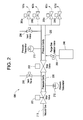
- FIG. 2 shows a detailed illustration of the exemplary fuel system 106 of FIG. 1 .
- the fuel system 106 comprises a piping configuration including pressure cavities 220 and 230 for supplying fuel to the gas turbine 102.
- the two pressure cavities 220 and 230 are in fluid communication with each other by a series of valves, which control the flow therebetween and, when operated in concert with each other, permit fuel to flow to the gas turbine 102 in a controlled manner to allow an operation of the combined cycle power plant.
- Pressure cavity 220 has a valve 201 on one side of the pressure cavity 220 that connects the pressure cavity 220 to a fuel inlet line 210 and permits flow therebetween.
- a vent valve 203 is connected to the pressure cavity 220 and allows the pressure cavity 220 to be vented to an appropriate venting receptacle when necessary.
- Valve 202 connects pressure cavity 220 to pressure cavity 230 and permits flow therebetween.
- Pressure cavity 230 comprises several exemplary gas control valves 205a, 205b, 205c and 205d, which connect the pressure cavity 230 to respective fuel lines 107a, 107b, 107c and 107d. While the exemplary pressure cavity 230 as illustrated in FIG. 2 comprises four such gas control valves, the pressure cavity 230 can include any number of gas control valves in alternate embodiments. Pressure cavity 230 further includes a vent valve 206 for venting of the pressure cavity 230 to an appropriate venting location when necessary. The vent valve 206 can be a single valve in one embodiment or can comprise a configuration of multiple vent valves in an alternate embodiment.
- Pressure cavity 230 also includes an isolation valve 208 that can be opened to allow a purge gas to enter into the pressure cavity 230 from an exemplary purge gas supply system 240.
- the purge gas forces fuel isolated in pressure chamber 230 into the combustion flame.
- the purge gas is thus forced through the pressure cavity 230 to the generator to extinguish a flame at the combustor.
- the purge gas then displaces fuel remaining in the generator from the generator system of FIG. 1 .
- the purge gas can be used to perform a tightness test of various valves of the fuel system 106.
- Pressure cavities 220 and 230 further include various exemplary pressure gauges 212 and 213 respectively coupled thereto.
- the control unit 140 of FIG. 1 can be coupled to the various pressure gauges to monitor the pressures at the pressure cavities 220 and 230.
- the control unit 140 can be used to monitor operating conditions of the fuel system during various operational stages, such as during online operation, during a shutdown sequence, during a startup sequence, during a purge sequence, after establishing a purge credit as described below, etc.
- two pressure gauges 212 and 213 are shown in FIG. 2 this is only meant for illustrative purposes and is not meant as a limitation of the disclosure.
- Pressure gauges can also be coupled to the various vent valves, gas control valves, isolation valves and stop valves of an exemplary fuel system and measurements obtained at these pressure gauges can be provided to the control unit 140 for monitoring and/or processing.
- valves of the fuel system 106 can be opened and closed according to any appropriate valve setting configuration.
- the valves as embodied by the disclosure, either alone or collectively, can comprise rotary valves, gate valves, stem valves, butterfly valves, ball valves, choke valves, or any other valve configuration.
- valves of the fuel system 106 can be controlled by any appropriate means, such as solenoid, manual, sensor controlled, remotely controlled or any other appropriate control, so the valves work as intended.
- valve 202 is closed to isolate fuel in the pressure chamber 230 and purge gas isolation valve 208 is opened to introduce the purge gas into the pressure 230. With valves 205a-205d open, the fuel is forced into the combustion chamber via the purge gas.
- Purge gas supply system 240 supplies a gaseous medium such as a purge gas to the fuel system in one embodiment of the present disclosure.
- the purge gas can be supplied from the power plant or from a dedicated system.
- the dedicated purge gas supply system 240 includes but is not limited to components to isolate, control pressure, prevent backflow, provide filtering of particulates, remove moisture and provide indication of successful operation to the controller.
- the gaseous medium can be used for a tightness test of the valves of the fuel system.
- the purge gas can be used to force fuel from the fuel supply and to extinguish a flame at the combustor section.
- the purge gas at the combustor purges the gas turbine and/or HRSG of volatile fuel remaining in the gas turbine/HRSG after extinguishing the flame.
- the present disclosure provides a method of shutting down a generator system in order to be in a ready state for restart, e.g. a "ready to start” condition, within a reduced amount of time from shutdown.
- a “ready to start” condition is a general indication that combustible gases are substantially diluted and/or removed from the generator and that the generator systems are in a desired state for start up of the generator.
- a “ready to start” condition can also involve removal of risks associated with remaining fuel in the gas turbine components, exhaust, and downstream equipment, placing the fuel system in a specific startup configuration, completing a leak test of the fuel system, securing the fuel system to a standby condition, and monitoring conditions after establishing the desired conditions.
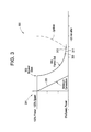
- FIG. 3 shows an exemplary shutdown and startup sequence in an exemplary embodiment of the present disclosure.
- the purge gas displaces remaining fuel from the generator components into the compressor coast down air flow during the shut down sequence of the generator.
- Coast down airflow generally refers to air flowing through the generator/combustor due to the residual (unpowered) rotation of the turbine blades of the turbine section and/or the coupled compressor blades of the compressor section after extinguishing of the combustion flame, known as flame-out, during shutdown of the generator.
- An inlet guide vane 109 of the gas turbine generator can be substantially closed upon shutdown or tripping of the gas turbine generator. The inlet guide vane 109 can be operated to provide an air flow for purging combustible gas from the gas turbine generator.
- the shutdown sequence includes at least the steps of 1) "flame-out” or extinguishing the combustor flame, 2) testing of valves in the fuel system, 3) displacing and diluting remaining fuel through the generator using the coast down airflow to purge remaining fuel from the generator, and 4) isolating a fuel for restart at the fuel system.
- these steps can be monitored by control unit 140 to ensure that the gas turbine 102 is prepared for a startup sequence.
- the generator is shut down as part of a planned shut down sequence.
- time 301 indicates a time at which the generator is taken offline.
- Line 320 indicates the amount of power contributed from the generator to an attached power grid.
- a breaker to the generator is opened to initiate the planned shut down sequence of the gas turbine.
- the generator is shut down due to a trip sequence. The generator can be tripped when a fault is detected.
- the breaker may be opened (time 303) simultaneously with taking the generator offline. In either sequence, at 303, fuel flow to the combustion section 110 is reduced to a specified setting to support the combustion flame.
- the fuel supply is isolated in pressure cavity 230 by closing valve 202.
- Purge gas isolation valve 208 is opened to provide a purge gas that pushes the isolated fuel supply from the pressure cavity 230 into the combustor.
- turbine blades and compressor blades still rotating provide a coast down airflow flowing through the generator.
- the combustion flame may be extinguished (at flame-out point 305) either when the air supplied to the flame falls below a flame threshold value or when the purge gas reaches the flame.
- the flame-out point 305 can be made to occur at a selected time.
- the purge gas is the swept through the gas turbine manifold to displace remaining fuel.
- Valves 205a-d are opened to allow the purge gas into the gas turbine to flow out the exhaust of the HRSG using the coast down airflow.
- Valve 202 can be closed to prevent upstream flow of the purge gas during the purge process.
- the fuel in the gas turbine manifold is diluted until the level of fuel falls below a designated value.
- Various parameters can be measured to ensure that residual fuel and/or volatile gases are below selected levels and/or are swept from volatile areas of the gas turbine to low temperature or non-volatile areas of the generator.
- the purge gas can be swept through the generator manifold beginning at flame-out 305. A test of the fuel system 106 is generally performed after a successful purge of the generator.
- a valve configuration of the fuel system is set in order to prevent leaks of fuel and to prepare the fuel system for a startup sequence.
- the fuel pressure plug is typically formed to provide pressure cavity 230 at a selected pressure and the pressure in pressure cavity 220 held at a low pressure through vent valve 203 to atmosphere.
- Successful completion of the valve test displacement of remaining fuel and the formation of a leak free shutoff therefore generates a "ready to start” condition indicating that the system is in a prepared state for a startup sequence.
- Exemplary time 313 indicates the beginning of a startup sequence once the "ready to start" condition is achieved.
- the present disclosure provides a method of shutting down a generator to prepare the generator for restart, the method including: initiating a power down sequence of a gas turbine of the generator from an operating state; forcing a purge gas into the gas turbine to extinguish a combustion flame in the gas turbine; and sweeping the purge gas through the gas turbine to displace the fuel from the gas turbine using a coast down airflow through the gas turbine during the power down sequence to prepare the generator for restart.
- Initiating the power down sequence can be part of either a planned shutdown sequence or in response to a tripping signal.
- Fuel is isolated at a fuel system coupled to the gas turbine, and the isolated fuel is forced from the fuel system using the purge gas.
- a pressure plug can be formed at the fuel system after sweeping the purge gas through the gas turbine.
- the combustion flame is extinguished at a predetermined time after initiation of the power down sequence.
- the predetermined time can be based on either a selected air pressure of airflow in the generator or a time at which the purge gas reaches the combustion flame.
- the purge gas can include at least one of nitrogen and compressed air and can be provided from either a combined cycle generator plant or a dedicated purge gas supply system.
- the generator is considered ready for restart when a measured concentration of the fuel in the generator falls below a selected threshold.
- the generator can also be considered ready for restart upon performing at least one of: 1) extinguishing the flame in the generator, 2) testing valves in a fuel system, 3) displacing and diluting remaining fuel through the generator using the coast down air flow and a purge gas, and 4) forming a leak-free isolated at the fuel system.
- the present disclosure provides a generator that includes: a combustion chamber; a fuel system coupled to the combustion chamber configured to provide a purge gas to extinguish a combustion flame in the combustion chamber; and a source of the purge gas configured to provide the purge gas to the fuel system , wherein the purge gas displaces fuel remaining in the generator after the combustion flame is extinguished during a shutdown sequence of the generator, wherein the purge gas is swept through the generator using a coast down airflow of the generator.
- the shutdown sequence may be a planned shutdown sequence or a shutdown sequence initiated in response to a tripping signal.
- the fuel system includes a pressure chamber configured to provide the purge gas to the generator.
- the pressure chamber includes a control valve configured to isolate a fuel at the pressure chamber and an isolation valve configured to allow the purge gas into the pressure chamber.
- the purge gas forces the isolated fuel from the pressure chamber to extinguish the flame at the combustion chamber.
- a control unit coupled to the generator can be used to determine a ready to start condition of the generator.
- the control can determine the ready to start condition when a measured concentration of the fuel in the generator falls below a selected threshold.
- the control unit can determine the ready to start condition by performing at least one of: 1) extinguishing the flame in the combustion chamber, 2) testing valves in the fuel system, 3) displacing and diluting remaining fuel through the generator using the coast down airflow and a purge gas, and 4) forming a leak-free isolation at the fuel system.
- the control unit may be further configured to control an inlet guide vane to provide an airflow for purging combustible gases from the generator.
- the control unit is further configured to perform the extinguishing of the combustion flame at a predetermined time after initiation of a power down sequence.
- the predetermined time for extinguishing the combustion flame can be based on a selected air pressure of airflow in the generator.
Landscapes
- Engineering & Computer Science (AREA)
- Mechanical Engineering (AREA)
- General Engineering & Computer Science (AREA)
- Chemical & Material Sciences (AREA)
- Combustion & Propulsion (AREA)
- Control Of Turbines (AREA)
- Feeding And Controlling Fuel (AREA)
- Control Of Eletrric Generators (AREA)
- Regulation And Control Of Combustion (AREA)
Abstract
Description
- The subject matter disclosed herein relates to methods and apparatus for shutting down a gas turbine generator for a fast restart. Gas turbine generators, which are often used in combined cycle power plants, are often shut down and started up depending on the demand for electricity, which is constantly fluctuating. Once a generator is shut down, a series of tests and preparatory steps are performed before the generator can be restarted. In one such preparatory step, residual combustible gas is purged from the generator. Prior methods for purging the residual combustible gas are initiated after the generator has come to a complete stop. Such purge methods limit how soon the generator can be returned to full power after shutdown. Therefore, the present disclosure provides a method of shutting down a generator that places the generator in a "ready to start" condition in a reduced amount of time.
- According to one aspect of the disclosure, a method of shutting down a generator to prepare the generator for restart is provided, the method including: initiating a power down sequence of a gas turbine of the generator from an operating state; forcing a purge gas into the gas turbine to extinguish a combustion flame in the gas turbine; and sweeping the purge gas through the gas turbine to displace the fuel from the gas turbine using a coast down airflow through the gas turbine during the power down sequence to prepare the generator for restart.
- According to another aspect of the disclosure, a generator is provided that includes: a combustion chamber; a fuel system coupled to the combustion chamber configured to provide a purge gas to extinguish a combustion flame in the combustion chamber; and a source of the purge gas configured to provide the purge gas to the fuel system, wherein the purge gas displaces fuel remaining in the generator after the combustion flame is extinguished during a shutdown sequence of the generator, wherein the purge gas is swept through the generator using a coast down airflow of the generator.
- These and other advantages and features will become more apparent from the following description taken in conjunction with the drawings.
- The subject matter, which is regarded as the invention, is particularly pointed out and distinctly claimed in the claims at the conclusion of the specification. The foregoing and other features, and advantages of the invention are apparent from the following detailed description taken in conjunction with the accompanying drawings in which:
-
FIG. 1 shows an exemplary combined gas turbine/heat recovery steam generator (GT/HRSG) system of the present disclosure generally used to generator power such as electrical power in a combined cycle power plant; -
FIG. 2 shows a detailed illustration of theexemplary fuel system 106 ofFIG. 1 ; and -
FIG. 3 shows an exemplary shutdown and startup sequence for providing a ready to start condition according to an exemplary embodiment of the present disclosure. - The detailed description explains embodiments of the invention, together with advantages and features, by way of example with reference to the drawings.
-
FIG. 1 shows an exemplary combined gas turbine/heat recovery steam generator (GT/HRSG)system 100 of the present disclosure generally used to generator power such as electrical power in a combined cycle power plant. The exemplary GT/HRSGsystem 100 includes a gas turbine (GT) 102, a heat recovery steam generator (HRSG) 104 and afuel system 106. Thefuel system 106 generally provides fuel to the gas turbine for combustion and is discussed in detail with respect toFIG. 2 . As shown inFIG. 1 , fourfuel lines fuel system 106 to thegas turbine 102. The number of fuel lines is not meant as a limitation of the disclosure and any number of fuel lines can be used in various embodiments of the disclosure. - The
exemplary gas turbine 102 typically includes acompressor section 108, acombustion section 110 and aturbine section 112. The compressor section includes a series of compressor stages, each stage including a plurality of compressor blades that rotate to compress air. Thecompressor section 108 generally receives ambient air at an inlet to the compressor section, compresses the air at the compressor stages and provides the compressed air at the outlet of the compressor section to thecombustion section 110. Aninlet guide vane 109 at the inlet can be opened and closed to regulate a flow of air through thecompressor section 108. In thecombustion section 110, fuel from thefuel system 106 is mixed with the compressed air from the compressor. The air/fuel mixture is then ignited using an ignition device such as a spark plug to create a working gas. The working gas is directed through theturbine section 112. Theturbine section 112 is made up of a serial arrangement of stages, each stage having rotating blades known as buckets. The rotating buckets are supported by a common rotary shaft. The working gas exiting thecombustion section 110 expands through the serial stages to cause rotation of the buckets and therefore of the rotary shaft. In one aspect, the rotary shaft of theturbine section 112 can be connected to the compression blades in the compressor section so that rotation of the rotary shaft drives air compression in thecompressor section 108. The rotary shaft also extends beyond the turbine section to an electric generator (not shown) where the rotary motion of the rotary shaft is converted into electrical power. Meanwhile the exhausted working gas from theturbine section 112 is directed toward the HRSG 104. - The HRSG 104 receives exhaust from the gas turbine and uses the exhaust as a heat source to drive one or more steam turbines. The HRSG includes an
inlet 120, a high pressure superheater 122 and one or more HSRG pressure sections124a, 124b and 124c, which are operable to generate steam at high pressure, intermediate pressure and/or low pressure, respectively. Exhaust gas from the HRSG is sent through HRSGoutlet duct 126 to an exhaust stack 124. - In an exemplary embodiment, the
gas turbine 102 andfuel system 106 are coupled to acontrol unit 140 configured to control various elements of the fuel system and gas turbine. Thecontrol unit 140 includes amemory 144, a set ofprograms 146 storing instructions therein for shutting down the generator according to the methods described herein, and aprocessor 142 having access to the set ofprograms 146 and to the contents of thememory 144. Theprocessor 142 is configured to run various programs of the present embodiment for shutting down the gas turbine and completing a displacement of remaining fuel in the gas turbine manifolds, exhaust, and attached equipment, among others. The control unit can control valve configurations at thefuel system 106 as well as monitor various parameters, such as pressure at thefuel system 106, gas levels in thegas turbine 102, etc. Amonitoring device 132 is coupled to the generator. In one embodiment, themonitoring device 132 generates a trip signal to thecontrol unit 140 wherein a fault occurs at the generator. The trip signal can be used to initiate a trip of the generator to shut down the generator. -
FIG. 2 shows a detailed illustration of theexemplary fuel system 106 ofFIG. 1 . Thefuel system 106 comprises a piping configuration includingpressure cavities gas turbine 102. The twopressure cavities gas turbine 102 in a controlled manner to allow an operation of the combined cycle power plant. -
Pressure cavity 220 has avalve 201 on one side of thepressure cavity 220 that connects thepressure cavity 220 to afuel inlet line 210 and permits flow therebetween. Avent valve 203 is connected to thepressure cavity 220 and allows thepressure cavity 220 to be vented to an appropriate venting receptacle when necessary. Valve 202 connectspressure cavity 220 topressure cavity 230 and permits flow therebetween. -
Pressure cavity 230 comprises several exemplarygas control valves pressure cavity 230 torespective fuel lines exemplary pressure cavity 230 as illustrated inFIG. 2 comprises four such gas control valves, thepressure cavity 230 can include any number of gas control valves in alternate embodiments.Pressure cavity 230 further includes avent valve 206 for venting of thepressure cavity 230 to an appropriate venting location when necessary. Thevent valve 206 can be a single valve in one embodiment or can comprise a configuration of multiple vent valves in an alternate embodiment.Pressure cavity 230 also includes anisolation valve 208 that can be opened to allow a purge gas to enter into thepressure cavity 230 from an exemplary purgegas supply system 240. The purge gas forces fuel isolated inpressure chamber 230 into the combustion flame. The purge gas is thus forced through thepressure cavity 230 to the generator to extinguish a flame at the combustor. The purge gas then displaces fuel remaining in the generator from the generator system ofFIG. 1 . Additionally, the purge gas can be used to perform a tightness test of various valves of thefuel system 106. -
Pressure cavities exemplary pressure gauges control unit 140 ofFIG. 1 can be coupled to the various pressure gauges to monitor the pressures at thepressure cavities control unit 140 can be used to monitor operating conditions of the fuel system during various operational stages, such as during online operation, during a shutdown sequence, during a startup sequence, during a purge sequence, after establishing a purge credit as described below, etc. Although twopressure gauges FIG. 2 this is only meant for illustrative purposes and is not meant as a limitation of the disclosure. Pressure gauges can also be coupled to the various vent valves, gas control valves, isolation valves and stop valves of an exemplary fuel system and measurements obtained at these pressure gauges can be provided to thecontrol unit 140 for monitoring and/or processing. - The valves of the
fuel system 106 can be opened and closed according to any appropriate valve setting configuration. The valves, as embodied by the disclosure, either alone or collectively, can comprise rotary valves, gate valves, stem valves, butterfly valves, ball valves, choke valves, or any other valve configuration. Further, valves of thefuel system 106 can be controlled by any appropriate means, such as solenoid, manual, sensor controlled, remotely controlled or any other appropriate control, so the valves work as intended. In one configuration,valve 202 is closed to isolate fuel in thepressure chamber 230 and purgegas isolation valve 208 is opened to introduce the purge gas into thepressure 230. Withvalves 205a-205d open, the fuel is forced into the combustion chamber via the purge gas. - Purge
gas supply system 240 supplies a gaseous medium such as a purge gas to the fuel system in one embodiment of the present disclosure. The purge gas can be supplied from the power plant or from a dedicated system. The dedicated purgegas supply system 240 includes but is not limited to components to isolate, control pressure, prevent backflow, provide filtering of particulates, remove moisture and provide indication of successful operation to the controller. In one valve configuration of the fuel system, the gaseous medium can be used for a tightness test of the valves of the fuel system. In another valve configuration of the fuel system, the purge gas can be used to force fuel from the fuel supply and to extinguish a flame at the combustor section. The purge gas at the combustor purges the gas turbine and/or HRSG of volatile fuel remaining in the gas turbine/HRSG after extinguishing the flame. - The present disclosure provides a method of shutting down a generator system in order to be in a ready state for restart, e.g. a "ready to start" condition, within a reduced amount of time from shutdown. A "ready to start" condition is a general indication that combustible gases are substantially diluted and/or removed from the generator and that the generator systems are in a desired state for start up of the generator. A "ready to start" condition can also involve removal of risks associated with remaining fuel in the gas turbine components, exhaust, and downstream equipment, placing the fuel system in a specific startup configuration, completing a leak test of the fuel system, securing the fuel system to a standby condition, and monitoring conditions after establishing the desired conditions.
-
FIG. 3 shows an exemplary shutdown and startup sequence in an exemplary embodiment of the present disclosure. In one aspect of the generator shutdown, the purge gas displaces remaining fuel from the generator components into the compressor coast down air flow during the shut down sequence of the generator. Coast down airflow generally refers to air flowing through the generator/combustor due to the residual (unpowered) rotation of the turbine blades of the turbine section and/or the coupled compressor blades of the compressor section after extinguishing of the combustion flame, known as flame-out, during shutdown of the generator. Aninlet guide vane 109 of the gas turbine generator can be substantially closed upon shutdown or tripping of the gas turbine generator. Theinlet guide vane 109 can be operated to provide an air flow for purging combustible gas from the gas turbine generator. In one aspect, the shutdown sequence includes at least the steps of 1) "flame-out" or extinguishing the combustor flame, 2) testing of valves in the fuel system, 3) displacing and diluting remaining fuel through the generator using the coast down airflow to purge remaining fuel from the generator, and 4) isolating a fuel for restart at the fuel system. In one embodiment, these steps can be monitored bycontrol unit 140 to ensure that thegas turbine 102 is prepared for a startup sequence. - In one embodiment, the generator is shut down as part of a planned shut down sequence. In a planned shutdown sequence,
time 301 indicates a time at which the generator is taken offline.Line 320 indicates the amount of power contributed from the generator to an attached power grid. Once the generator power is reduced to a designated setting (at time 303), a breaker to the generator is opened to initiate the planned shut down sequence of the gas turbine. In an alternate embodiment, the generator is shut down due to a trip sequence. The generator can be tripped when a fault is detected. Thus, in a trip sequence, the breaker may be opened (time 303) simultaneously with taking the generator offline. In either sequence, at 303, fuel flow to thecombustion section 110 is reduced to a specified setting to support the combustion flame. In addition, the fuel supply is isolated inpressure cavity 230 by closingvalve 202. Purgegas isolation valve 208 is opened to provide a purge gas that pushes the isolated fuel supply from thepressure cavity 230 into the combustor. During the shutdown sequence, turbine blades and compressor blades (still rotating) provide a coast down airflow flowing through the generator. The combustion flame may be extinguished (at flame-out point 305) either when the air supplied to the flame falls below a flame threshold value or when the purge gas reaches the flame. Thus, in various embodiments, the flame-out point 305 can be made to occur at a selected time. - At 309, the purge gas is the swept through the gas turbine manifold to displace remaining fuel.
Valves 205a-d are opened to allow the purge gas into the gas turbine to flow out the exhaust of the HRSG using the coast down airflow.Valve 202 can be closed to prevent upstream flow of the purge gas during the purge process. In various embodiments, the fuel in the gas turbine manifold is diluted until the level of fuel falls below a designated value. Various parameters can be measured to ensure that residual fuel and/or volatile gases are below selected levels and/or are swept from volatile areas of the gas turbine to low temperature or non-volatile areas of the generator. In an alternate embodiment, the purge gas can be swept through the generator manifold beginning at flame-out 305. A test of thefuel system 106 is generally performed after a successful purge of the generator. - At
time 311, a valve configuration of the fuel system is set in order to prevent leaks of fuel and to prepare the fuel system for a startup sequence. The fuel pressure plug is typically formed to providepressure cavity 230 at a selected pressure and the pressure inpressure cavity 220 held at a low pressure throughvent valve 203 to atmosphere. Successful completion of the valve test, displacement of remaining fuel and the formation of a leak free shutoff therefore generates a "ready to start" condition indicating that the system is in a prepared state for a startup sequence.Exemplary time 313 indicates the beginning of a startup sequence once the "ready to start" condition is achieved. - Therefore, in one aspect, the present disclosure provides a method of shutting down a generator to prepare the generator for restart, the method including: initiating a power down sequence of a gas turbine of the generator from an operating state; forcing a purge gas into the gas turbine to extinguish a combustion flame in the gas turbine; and sweeping the purge gas through the gas turbine to displace the fuel from the gas turbine using a coast down airflow through the gas turbine during the power down sequence to prepare the generator for restart. Initiating the power down sequence can be part of either a planned shutdown sequence or in response to a tripping signal. Fuel is isolated at a fuel system coupled to the gas turbine, and the isolated fuel is forced from the fuel system using the purge gas. A pressure plug can be formed at the fuel system after sweeping the purge gas through the gas turbine. In one embodiment, the combustion flame is extinguished at a predetermined time after initiation of the power down sequence. The predetermined time can be based on either a selected air pressure of airflow in the generator or a time at which the purge gas reaches the combustion flame. The purge gas can include at least one of nitrogen and compressed air and can be provided from either a combined cycle generator plant or a dedicated purge gas supply system. The generator is considered ready for restart when a measured concentration of the fuel in the generator falls below a selected threshold. The generator can also be considered ready for restart upon performing at least one of: 1) extinguishing the flame in the generator, 2) testing valves in a fuel system, 3) displacing and diluting remaining fuel through the generator using the coast down air flow and a purge gas, and 4) forming a leak-free isolated at the fuel system.
- In another aspect, the present disclosure provides a generator that includes: a combustion chamber; a fuel system coupled to the combustion chamber configured to provide a purge gas to extinguish a combustion flame in the combustion chamber; and a source of the purge gas configured to provide the purge gas to the fuel system , wherein the purge gas displaces fuel remaining in the generator after the combustion flame is extinguished during a shutdown sequence of the generator, wherein the purge gas is swept through the generator using a coast down airflow of the generator. The shutdown sequence may be a planned shutdown sequence or a shutdown sequence initiated in response to a tripping signal. The fuel system includes a pressure chamber configured to provide the purge gas to the generator. The pressure chamber includes a control valve configured to isolate a fuel at the pressure chamber and an isolation valve configured to allow the purge gas into the pressure chamber. The purge gas forces the isolated fuel from the pressure chamber to extinguish the flame at the combustion chamber. A control unit coupled to the generator can be used to determine a ready to start condition of the generator. The control can determine the ready to start condition when a measured concentration of the fuel in the generator falls below a selected threshold. Also, the control unit can determine the ready to start condition by performing at least one of: 1) extinguishing the flame in the combustion chamber, 2) testing valves in the fuel system, 3) displacing and diluting remaining fuel through the generator using the coast down airflow and a purge gas, and 4) forming a leak-free isolation at the fuel system. The control unit may be further configured to control an inlet guide vane to provide an airflow for purging combustible gases from the generator. The control unit is further configured to perform the extinguishing of the combustion flame at a predetermined time after initiation of a power down sequence. The predetermined time for extinguishing the combustion flame can be based on a selected air pressure of airflow in the generator.
- While the invention has been described in detail in connection with only a limited number of embodiments, it should be readily understood that the invention is not limited to such disclosed embodiments. Rather, the invention can be modified to incorporate any number of variations, alterations, substitutions or equivalent arrangements not heretofore described, but which are commensurate with the spirit and scope of the invention. Additionally, while various embodiments of the invention have been described, it is to be understood that aspects of the invention may include only some of the described embodiments. Accordingly, the invention is not to be seen as limited by the foregoing description, but is only limited by the scope of the appended claims.
- Various aspects and embodiments of the present invention are defined by the following numbered clauses:
- 1. A method of shutting down a generator to prepare the generator for restart, comprising
initiating a power down sequence of a gas turbine of the generator from an operating state;
forcing a purge gas into the gas turbine to extinguish a combustion flame in the gas turbine; and
sweeping the purge gas through the gas turbine to displace the fuel from the gas turbine using a coast down airflow through the gas turbine during the power down sequence to prepare the generator for restart. - 2. The method of clause 1, further comprising initiating the power down sequence as one of: (i) a planned shutdown sequence; and (ii) in response to a tripping signal.
- 3. The method of any preceding clause, further comprising isolating a fuel at a fuel system coupled to the gas turbine and forcing the fuel from the fuel system using the purge gas.
- 4. The method of any preceding clause, further comprising forming a pressure plug at the fuel system after sweeping the purge gas through the gas turbine.
- 5. The method of any preceding clause, further comprising extinguishing the combustion flame at a predetermined time after initiation of the power down sequence.
- 6. The method of any preceding clause, wherein the predetermined time for extinguishing the combustion flame is based on one of: (i) a selected air pressure of airflow in the generator; and (ii) a time at which a purge gas reaches the combustion flame.
- 7. The method of any preceding clause, wherein the purge gas includes at least one of nitrogen and compressed air.
- 8. The method of any preceding clause, wherein the purge gas is provided from at least one of: (i) a combined cycle generator plant; and (ii) a dedicate purge gas supply system.
- 9. The method of any preceding clause, further comprising determining a ready to start condition when a measured concentration of the fuel in the generator falls below a selected threshold.
- 10. The method of any preceding clause, further comprising obtaining a determining a ready to start condition upon performing at least one of: 1) extinguishing the flame in the generator, 2) testing valves in a fuel system, 3) displacing and diluting remaining fuel through the generator using the coast down air flow and a purge gas, and 4) forming a leak-free isolated at the fuel system.
- 11. A generator, comprising:
- a combustion chamber;
- a fuel system coupled to the combustion chamber configured to provide a purge gas to extinguish a combustion flame in the combustion chamber; and
- a source of the purge gas configured to provide the purge gas to the fuel system, wherein the purge gas displaces fuel remaining in the generator after the combustion flame is extinguished during a shutdown sequence of the generator, wherein the purge gas is swept through the generator using a coast down airflow of the generator.
- 12. The generator of any preceding clause, wherein the shutdown sequence is initiated from the group consisting of: (i) a planned shutdown sequence; and (ii) a shutdown sequence in response to a tripping signal.
- 13. The generator of any preceding clause, wherein the fuel system includes a pressure chamber configured to provide the purge gas to the generator, the pressure chamber having a control valve configured to isolate a fuel at the pressure chamber and an isolation valve configured to allow the purge gas into the pressure chamber.
- 14. The generator of any preceding clause, wherein the purge gas forces the isolated fuel from the pressure chamber to extinguish the flame at the combustion chamber.
- 15. The generator of any preceding clause, further comprises a control unit coupled to the generator configured to determine a ready to start condition of the generator.
- 16. The generator of any preceding clause, wherein the control unit determines the ready to start condition when a measured concentration of the fuel in the generator falls below a selected threshold.
- 17. The generator of preceding clause, wherein the control unit is configured to determine the ready to start condition upon performing at least one of: 1) extinguishing the flame in the combustion chamber, 2) testing valves in the fuel system, 3) displacing and diluting remaining fuel through the generator using the coast down airflow and a purge gas, and 4) forming a leak-free isolation at the fuel system.
- 18. The generator of any preceding clauses, wherein the control unit is further configured to control an inlet guide vane to provide an airflow for purging combustible gases from the generator.
- 19. The generator of any preceding clause, wherein the control unit is further configured to perform the extinguishing of the combustion flame at a predetermined time after initiation of a power down sequence.
- 20. The generator of any preceding clause, wherein the predetermined time for extinguishing the combustion flame is based on a selected air pressure of airflow in the generator.
Claims (15)
- A method of shutting down a generator to prepare the generator for restart, comprising
initiating a power down sequence of a gas turbine (102) of the generator from an operating state;
forcing a purge gas into the gas turbine to extinguish a combustion flame in the gas turbine (102); and
sweeping the purge gas through the gas turbine (102) to displace the fuel from the gas turbine using a coast down airflow through the gas turbine during the power down sequence to prepare the generator for restart. - The method of claim 1, further comprising initiating the power down sequence as one of: (i) a planned shutdown sequence; and (ii) in response to a tripping signal.
- The method of claim 1 or claim 2, further comprising isolating a fuel at a fuel system (106) coupled to the gas turbine (102) and forcing the fuel from the fuel system using the purge gas.
- The method of claim 3, further comprising forming a pressure plug at the fuel system (106) after sweeping the purge gas through the gas turbine (102).
- The method of any preceding claim, further comprising extinguishing the combustion flame at a predetermined time after initiation of the power down sequence, wherein the predetermined time for extinguishing the combustion flame is based on one of: (i) a selected air pressure of airflow in the generator; and (ii) a time at which a purge gas reaches the combustion flame.
- The method of any preceding claim, further comprising determining a ready to start condition when a measured concentration of the fuel in the generator falls below a selected threshold.
- The method of claim 6, further comprising obtaining a determining a ready to start condition upon performing at least one of: 1) extinguishing the flame in the generator, 2) testing valves in a fuel system, 3) displacing and diluting remaining fuel through the generator using the coast down air flow and a purge gas, and 4) forming a leak-free isolated at the fuel system.
- A generator, comprising:a combustion chamber (110);a fuel system (106) coupled to the combustion chamber configured to provide a purge gas to extinguish a combustion flame in the combustion chamber; anda source (240) of the purge gas configured to provide the purge gas to the fuel system (106), wherein the purge gas displaces fuel remaining in the generator after the combustion flame is extinguished during a shutdown sequence of the generator, wherein the purge gas is swept through the generator using a coast down airflow of the generator.
- The generator of claim 8, wherein the shutdown sequence is initiated from the group consisting of: (i) a planned shutdown sequence; and (ii) a shutdown sequence in response to a tripping signal.
- The generator of claim 8 or claim 9, wherein the fuel system (106) includes a pressure chamber configured to provide the purge gas to the generator, the pressure chamber having a control valve configured to isolate a fuel at the pressure chamber and an isolation valve configured to allow the purge gas into the pressure chamber, wherein preferably the purge gas forces the isolated fuel from the pressure chamber to extinguish the flame at the combustion chamber.
- The generator of claim 8, 9 or 10, further comprises a control unit (140) coupled to the generator configured to determine a ready to start condition of the generator.
- The generator of claim 11, wherein the control unit (140) determines the ready to start condition when a measured concentration of the fuel in the generator falls below a selected threshold.
- The generator of claim 11 or claim 12, wherein the control unit (140) is configured to determine the ready to start condition upon performing at least one of: 1) extinguishing the flame in the combustion chamber, 2) testing valves in the fuel system, 3) displacing and diluting remaining fuel through the generator using the coast down airflow and a purge gas, and 4) forming a leak-free isolation at the fuel system.
- The generator of claim 11, 12 or 13, wherein the control unit (140) is further configured to control an inlet guide vane (109) to provide an airflow for purging combustible gases from the generator.
- The generator of claim 11, 12, 13 or 14, wherein the control unit (140) is further configured to perform the extinguishing of the combustion flame at a predetermined time after initiation of a power down sequence, wherein preferably the predetermined time for extinguishing the combustion flame is based on a selected air pressure of airflow in the generator.
Applications Claiming Priority (1)
| Application Number | Priority Date | Filing Date | Title |
|---|---|---|---|
| US13/490,091 US20120240591A1 (en) | 2007-12-10 | 2012-06-06 | Method for shutting down a generator to prepare the generator for restart |
Publications (2)
| Publication Number | Publication Date |
|---|---|
| EP2672076A2 true EP2672076A2 (en) | 2013-12-11 |
| EP2672076A3 EP2672076A3 (en) | 2017-07-19 |
Family
ID=48607088
Family Applications (1)
| Application Number | Title | Priority Date | Filing Date |
|---|---|---|---|
| EP13170618.6A Withdrawn EP2672076A3 (en) | 2012-06-06 | 2013-06-05 | Method for Shutting Down a Generator to Prepare the Generator for Restart |
Country Status (4)
| Country | Link |
|---|---|
| EP (1) | EP2672076A3 (en) |
| JP (1) | JP2013253602A (en) |
| CN (1) | CN103470387A (en) |
| RU (1) | RU2622576C2 (en) |
Cited By (8)
| Publication number | Priority date | Publication date | Assignee | Title |
|---|---|---|---|---|
| FR3018561A1 (en) * | 2014-03-12 | 2015-09-18 | Ge Energy Products France Snc | METHOD FOR MONITORING THE OPERATION OF VALVES OF A GAS TURBINE GAS SUPPLY DEVICE |
| US10082087B2 (en) | 2016-08-25 | 2018-09-25 | General Electric Company | Systems and methods to improve shut-down purge flow in a gas turbine system |
| US10082091B2 (en) | 2016-08-25 | 2018-09-25 | General Electric Company | Systems and methods to improve shut-down purge flow in a gas turbine system |
| US10082089B2 (en) | 2016-08-25 | 2018-09-25 | General Electric Company | Systems and methods to improve shut-down purge flow in a gas turbine system |
| US10082090B2 (en) | 2016-08-25 | 2018-09-25 | General Electric Company | Systems and methods to improve shut-down purge flow in a gas turbine system |
| EP3283369A4 (en) * | 2015-04-15 | 2018-12-05 | Sikorsky Aircraft Corporation | Inlet guide vane control for aircraft single engine operation |
| EP3511537A1 (en) * | 2018-01-12 | 2019-07-17 | Mitsubishi Hitachi Power Systems, Ltd. | Gas turbine cogeneration system and operation mode change method therefor |
| CN117795183A (en) * | 2021-08-04 | 2024-03-29 | 诺沃皮尼奥内技术股份有限公司 | Improved method for estimating and setting exhaust purge times in combustion systems and combustion systems thereof |
Families Citing this family (2)
| Publication number | Priority date | Publication date | Assignee | Title |
|---|---|---|---|---|
| JP7137397B2 (en) * | 2018-08-08 | 2022-09-14 | 川崎重工業株式会社 | Combined cycle power plant |
| CN118401746A (en) * | 2022-01-24 | 2024-07-26 | 三菱重工业株式会社 | Gas turbine control device, gas turbine, and gas turbine control method |
Family Cites Families (15)
| Publication number | Priority date | Publication date | Assignee | Title |
|---|---|---|---|---|
| US4041695A (en) * | 1975-11-21 | 1977-08-16 | The Garrett Corporation | Fuel system pneumatic purge apparatus and method |
| JPS5529076A (en) * | 1978-08-24 | 1980-03-01 | Toshiba Corp | Controller for gas turbine |
| JPS5918240A (en) * | 1982-07-23 | 1984-01-30 | Nissan Motor Co Ltd | Control apparatus for gas-turbine engine |
| SU1710803A1 (en) * | 1989-12-05 | 1992-02-07 | Ленинградское объединение "Пролетарский завод" | Gas-turbine plant control system |
| JPH07253030A (en) * | 1994-03-15 | 1995-10-03 | Mitsubishi Heavy Ind Ltd | Gas turbine restarting method |
| US5819539A (en) * | 1996-12-30 | 1998-10-13 | Combustion Engineering, Inc. | Detecting and purging combustible gases from heat recovery steam generator cavities |
| JPH11210492A (en) * | 1998-01-20 | 1999-08-03 | Toshiba Corp | Fuel supply apparatus for gas turbine plant, warm-up operation method and cooling operation method for the apparatus |
| US6792760B2 (en) * | 2002-03-11 | 2004-09-21 | Alstom Technology Ltd | Method for operating a turbine |
| US7104070B2 (en) * | 2004-03-04 | 2006-09-12 | General Electric Company | Liquid fuel nozzle apparatus with passive water injection purge |
| JP4865476B2 (en) * | 2006-09-28 | 2012-02-01 | 三菱重工業株式会社 | Gas turbine start / stop method and start / stop control device |
| US7770400B2 (en) * | 2006-12-26 | 2010-08-10 | General Electric Company | Non-linear fuel transfers for gas turbines |
| US8510013B2 (en) * | 2009-05-04 | 2013-08-13 | General Electric Company | Gas turbine shutdown |
| US20100275608A1 (en) * | 2009-05-04 | 2010-11-04 | General Electric Company | Systems and Methods for Rapid Turbine Deceleration |
| US8955334B2 (en) * | 2010-07-22 | 2015-02-17 | General Electric Company | Systems and methods for controlling the startup of a gas turbine |
| RU2451921C1 (en) * | 2010-10-07 | 2012-05-27 | Закрытое Акционерное Общество Научно-Производственная Фирма "Газ-Система-Сервис" | Method of technical control of gas-turbine installation |
-
2013
- 2013-06-04 JP JP2013117426A patent/JP2013253602A/en not_active Ceased
- 2013-06-05 EP EP13170618.6A patent/EP2672076A3/en not_active Withdrawn
- 2013-06-05 RU RU2013125744A patent/RU2622576C2/en not_active IP Right Cessation
- 2013-06-06 CN CN2013102239718A patent/CN103470387A/en active Pending
Non-Patent Citations (1)
| Title |
|---|
| None |
Cited By (10)
| Publication number | Priority date | Publication date | Assignee | Title |
|---|---|---|---|---|
| FR3018561A1 (en) * | 2014-03-12 | 2015-09-18 | Ge Energy Products France Snc | METHOD FOR MONITORING THE OPERATION OF VALVES OF A GAS TURBINE GAS SUPPLY DEVICE |
| EP3283369A4 (en) * | 2015-04-15 | 2018-12-05 | Sikorsky Aircraft Corporation | Inlet guide vane control for aircraft single engine operation |
| US10738698B2 (en) | 2015-04-15 | 2020-08-11 | Sikorsky Aircraft Corporation | Inlet guide vane control for aircraft single engine operation |
| US10082087B2 (en) | 2016-08-25 | 2018-09-25 | General Electric Company | Systems and methods to improve shut-down purge flow in a gas turbine system |
| US10082091B2 (en) | 2016-08-25 | 2018-09-25 | General Electric Company | Systems and methods to improve shut-down purge flow in a gas turbine system |
| US10082089B2 (en) | 2016-08-25 | 2018-09-25 | General Electric Company | Systems and methods to improve shut-down purge flow in a gas turbine system |
| US10082090B2 (en) | 2016-08-25 | 2018-09-25 | General Electric Company | Systems and methods to improve shut-down purge flow in a gas turbine system |
| EP3511537A1 (en) * | 2018-01-12 | 2019-07-17 | Mitsubishi Hitachi Power Systems, Ltd. | Gas turbine cogeneration system and operation mode change method therefor |
| US11156130B2 (en) | 2018-01-12 | 2021-10-26 | Mitsubishi Power, Ltd. | Gas turbine cogeneration system and operation mode change method therefor |
| CN117795183A (en) * | 2021-08-04 | 2024-03-29 | 诺沃皮尼奥内技术股份有限公司 | Improved method for estimating and setting exhaust purge times in combustion systems and combustion systems thereof |
Also Published As
| Publication number | Publication date |
|---|---|
| CN103470387A (en) | 2013-12-25 |
| JP2013253602A (en) | 2013-12-19 |
| RU2622576C2 (en) | 2017-06-16 |
| RU2013125744A (en) | 2014-12-10 |
| EP2672076A3 (en) | 2017-07-19 |
Similar Documents
| Publication | Publication Date | Title |
|---|---|---|
| US20120240591A1 (en) | Method for shutting down a generator to prepare the generator for restart | |
| EP2672076A2 (en) | Method for Shutting Down a Generator to Prepare the Generator for Restart | |
| JP2013253602A5 (en) | ||
| CN101290342B (en) | Hydroelectric units black start-up ability verification test method | |
| US10082089B2 (en) | Systems and methods to improve shut-down purge flow in a gas turbine system | |
| US20130104516A1 (en) | Method of monitoring an operation of a compressor bleed valve | |
| CA3068610C (en) | Method and system for safe gas turbine startup | |
| US10082087B2 (en) | Systems and methods to improve shut-down purge flow in a gas turbine system | |
| EP3460438B1 (en) | Gas turbomachine leak detection system and method | |
| US10082090B2 (en) | Systems and methods to improve shut-down purge flow in a gas turbine system | |
| CN110030090A (en) | Gas turbine co-generation unit and its execution switching method | |
| US10480420B2 (en) | Methods and systems for controlling turbine powered system to reduce startup time | |
| US10082091B2 (en) | Systems and methods to improve shut-down purge flow in a gas turbine system | |
| US9822707B2 (en) | Vent system for use in a gas turbine and method of operating thereof | |
| US9677686B2 (en) | Control process for operation of valves of a gas supply device of the gas turbine | |
| EP2746555A2 (en) | Fuel routing system of a gas turbine engine and method of routing fuel | |
| CN113339252A (en) | Water supply characteristic test method for high-capacity electric pump with 100% steam pump unit | |
| EP3171005A1 (en) | Fuel supply system for use in a gas turbine engine and method of controlling an overspeed event therein | |
| US10704427B2 (en) | Method to diagnose power plant degradation using efficiency models | |
| Teplov et al. | Thermal tests of the SGT5-4000F gas-turbine plant of the PGU-420T power-generating unit at combined heat and power plant 16 of Mosenergo | |
| KR101631417B1 (en) | Display method for Total Monitoring Of Turbine for the Power Plant | |
| CN107731324B (en) | A system and method for simulating summer working conditions for thermal performance test of nuclear power plant units | |
| CN114813134B (en) | Inspection method for oiling device of high-temperature reactor steam turbine | |
| CN117795183A (en) | Improved method for estimating and setting exhaust purge times in combustion systems and combustion systems thereof | |
| CN120990752A (en) | An optimized method and system for starting and cleaning a V94.2 gas turbine. |
Legal Events
| Date | Code | Title | Description |
|---|---|---|---|
| PUAI | Public reference made under article 153(3) epc to a published international application that has entered the european phase |
Free format text: ORIGINAL CODE: 0009012 |
|
| AK | Designated contracting states |
Kind code of ref document: A2 Designated state(s): AL AT BE BG CH CY CZ DE DK EE ES FI FR GB GR HR HU IE IS IT LI LT LU LV MC MK MT NL NO PL PT RO RS SE SI SK SM TR |
|
| AX | Request for extension of the european patent |
Extension state: BA ME |
|
| PUAL | Search report despatched |
Free format text: ORIGINAL CODE: 0009013 |
|
| AK | Designated contracting states |
Kind code of ref document: A3 Designated state(s): AL AT BE BG CH CY CZ DE DK EE ES FI FR GB GR HR HU IE IS IT LI LT LU LV MC MK MT NL NO PL PT RO RS SE SI SK SM TR |
|
| AX | Request for extension of the european patent |
Extension state: BA ME |
|
| RIC1 | Information provided on ipc code assigned before grant |
Ipc: F01D 21/00 20060101ALI20170613BHEP Ipc: F02C 7/232 20060101ALI20170613BHEP Ipc: F01D 25/00 20060101AFI20170613BHEP Ipc: F02C 7/26 20060101ALI20170613BHEP Ipc: F01D 19/00 20060101ALI20170613BHEP Ipc: F02C 7/22 20060101ALI20170613BHEP |
|
| STAA | Information on the status of an ep patent application or granted ep patent |
Free format text: STATUS: THE APPLICATION IS DEEMED TO BE WITHDRAWN |
|
| 18D | Application deemed to be withdrawn |
Effective date: 20180103 |