EP2672065A2 - Shroud for a turbine, corresponding turbine and method of assembling the same - Google Patents
Shroud for a turbine, corresponding turbine and method of assembling the same Download PDFInfo
- Publication number
- EP2672065A2 EP2672065A2 EP13170855.4A EP13170855A EP2672065A2 EP 2672065 A2 EP2672065 A2 EP 2672065A2 EP 13170855 A EP13170855 A EP 13170855A EP 2672065 A2 EP2672065 A2 EP 2672065A2
- Authority
- EP
- European Patent Office
- Prior art keywords
- shroud
- turbine
- housing
- bucket
- groove
- Prior art date
- Legal status (The legal status is an assumption and is not a legal conclusion. Google has not performed a legal analysis and makes no representation as to the accuracy of the status listed.)
- Granted
Links
Images




Classifications
-
- F—MECHANICAL ENGINEERING; LIGHTING; HEATING; WEAPONS; BLASTING
- F01—MACHINES OR ENGINES IN GENERAL; ENGINE PLANTS IN GENERAL; STEAM ENGINES
- F01D—NON-POSITIVE DISPLACEMENT MACHINES OR ENGINES, e.g. STEAM TURBINES
- F01D5/00—Blades; Blade-carrying members; Heating, heat-insulating, cooling or antivibration means on the blades or the members
- F01D5/12—Blades
- F01D5/14—Form or construction
- F01D5/141—Shape, i.e. outer, aerodynamic form
- F01D5/142—Shape, i.e. outer, aerodynamic form of the blades of successive rotor or stator blade-rows
- F01D5/143—Contour of the outer or inner working fluid flow path wall, i.e. shroud or hub contour
-
- F—MECHANICAL ENGINEERING; LIGHTING; HEATING; WEAPONS; BLASTING
- F01—MACHINES OR ENGINES IN GENERAL; ENGINE PLANTS IN GENERAL; STEAM ENGINES
- F01D—NON-POSITIVE DISPLACEMENT MACHINES OR ENGINES, e.g. STEAM TURBINES
- F01D9/00—Stators
- F01D9/02—Nozzles; Nozzle boxes; Stator blades; Guide conduits, e.g. individual nozzles
- F01D9/04—Nozzles; Nozzle boxes; Stator blades; Guide conduits, e.g. individual nozzles forming ring or sector
-
- F—MECHANICAL ENGINEERING; LIGHTING; HEATING; WEAPONS; BLASTING
- F01—MACHINES OR ENGINES IN GENERAL; ENGINE PLANTS IN GENERAL; STEAM ENGINES
- F01D—NON-POSITIVE DISPLACEMENT MACHINES OR ENGINES, e.g. STEAM TURBINES
- F01D11/00—Preventing or minimising internal leakage of working-fluid, e.g. between stages
- F01D11/08—Preventing or minimising internal leakage of working-fluid, e.g. between stages for sealing space between rotor blade tips and stator
- F01D11/12—Preventing or minimising internal leakage of working-fluid, e.g. between stages for sealing space between rotor blade tips and stator using a rubstrip, e.g. erodible. deformable or resiliently-biased part
-
- F—MECHANICAL ENGINEERING; LIGHTING; HEATING; WEAPONS; BLASTING
- F05—INDEXING SCHEMES RELATING TO ENGINES OR PUMPS IN VARIOUS SUBCLASSES OF CLASSES F01-F04
- F05D—INDEXING SCHEME FOR ASPECTS RELATING TO NON-POSITIVE-DISPLACEMENT MACHINES OR ENGINES, GAS-TURBINES OR JET-PROPULSION PLANTS
- F05D2240/00—Components
- F05D2240/10—Stators
- F05D2240/11—Shroud seal segments
-
- F—MECHANICAL ENGINEERING; LIGHTING; HEATING; WEAPONS; BLASTING
- F05—INDEXING SCHEMES RELATING TO ENGINES OR PUMPS IN VARIOUS SUBCLASSES OF CLASSES F01-F04
- F05D—INDEXING SCHEME FOR ASPECTS RELATING TO NON-POSITIVE-DISPLACEMENT MACHINES OR ENGINES, GAS-TURBINES OR JET-PROPULSION PLANTS
- F05D2250/00—Geometry
- F05D2250/30—Arrangement of components
- F05D2250/38—Arrangement of components angled, e.g. sweep angle
-
- F—MECHANICAL ENGINEERING; LIGHTING; HEATING; WEAPONS; BLASTING
- F05—INDEXING SCHEMES RELATING TO ENGINES OR PUMPS IN VARIOUS SUBCLASSES OF CLASSES F01-F04
- F05D—INDEXING SCHEME FOR ASPECTS RELATING TO NON-POSITIVE-DISPLACEMENT MACHINES OR ENGINES, GAS-TURBINES OR JET-PROPULSION PLANTS
- F05D2250/00—Geometry
- F05D2250/70—Shape
- F05D2250/71—Shape curved
-
- F—MECHANICAL ENGINEERING; LIGHTING; HEATING; WEAPONS; BLASTING
- F05—INDEXING SCHEMES RELATING TO ENGINES OR PUMPS IN VARIOUS SUBCLASSES OF CLASSES F01-F04
- F05D—INDEXING SCHEME FOR ASPECTS RELATING TO NON-POSITIVE-DISPLACEMENT MACHINES OR ENGINES, GAS-TURBINES OR JET-PROPULSION PLANTS
- F05D2260/00—Function
- F05D2260/60—Fluid transfer
- F05D2260/602—Drainage
- F05D2260/6022—Drainage of leakage having past a seal
-
- Y—GENERAL TAGGING OF NEW TECHNOLOGICAL DEVELOPMENTS; GENERAL TAGGING OF CROSS-SECTIONAL TECHNOLOGIES SPANNING OVER SEVERAL SECTIONS OF THE IPC; TECHNICAL SUBJECTS COVERED BY FORMER USPC CROSS-REFERENCE ART COLLECTIONS [XRACs] AND DIGESTS
- Y10—TECHNICAL SUBJECTS COVERED BY FORMER USPC
- Y10T—TECHNICAL SUBJECTS COVERED BY FORMER US CLASSIFICATION
- Y10T29/00—Metal working
- Y10T29/49—Method of mechanical manufacture
- Y10T29/49229—Prime mover or fluid pump making
- Y10T29/49236—Fluid pump or compressor making
-
- Y—GENERAL TAGGING OF NEW TECHNOLOGICAL DEVELOPMENTS; GENERAL TAGGING OF CROSS-SECTIONAL TECHNOLOGIES SPANNING OVER SEVERAL SECTIONS OF THE IPC; TECHNICAL SUBJECTS COVERED BY FORMER USPC CROSS-REFERENCE ART COLLECTIONS [XRACs] AND DIGESTS
- Y10—TECHNICAL SUBJECTS COVERED BY FORMER USPC
- Y10T—TECHNICAL SUBJECTS COVERED BY FORMER US CLASSIFICATION
- Y10T29/00—Metal working
- Y10T29/49—Method of mechanical manufacture
- Y10T29/49316—Impeller making
- Y10T29/4932—Turbomachine making
-
- Y—GENERAL TAGGING OF NEW TECHNOLOGICAL DEVELOPMENTS; GENERAL TAGGING OF CROSS-SECTIONAL TECHNOLOGIES SPANNING OVER SEVERAL SECTIONS OF THE IPC; TECHNICAL SUBJECTS COVERED BY FORMER USPC CROSS-REFERENCE ART COLLECTIONS [XRACs] AND DIGESTS
- Y10—TECHNICAL SUBJECTS COVERED BY FORMER USPC
- Y10T—TECHNICAL SUBJECTS COVERED BY FORMER US CLASSIFICATION
- Y10T29/00—Metal working
- Y10T29/49—Method of mechanical manufacture
- Y10T29/49316—Impeller making
- Y10T29/4932—Turbomachine making
- Y10T29/49323—Assembling fluid flow directing devices, e.g., stators, diaphragms, nozzles
Definitions
- the present invention relates generally to rotary machines, and more particularly, to methods and apparatus to facilitate fluid flow within the rotary machine by reducing fluid leakage losses and fluid mixing losses within the rotary machine.
- Rotary machines such as gas turbines, are used to generate power for electric generators.
- a gas turbine has a gas path which typically includes, in serial-flow relationship, an air intake (or inlet), a compressor, a combustor, a turbine, and a gas outlet (or exhaust nozzle).
- Compressor and turbine sections include at least one row of circumferentially spaced rotating buckets or blades positioned within a housing.
- Turbine efficiency depends at least in part on a radial clearance or gap between tips of the rotating buckets and a shroud coupled to the surrounding housing.
- the clearance is needed to avoid contact or rubbing between the bucket tips and the shroud which results in a design limitation for the size of the clearance. If the clearance is too large, enhanced gas flow may leak through the clearance gaps, thus decreasing the turbine's efficiency. Leakage flow, either out of the flow path or into the flow path, from an area of higher pressure to an area of lower pressure, is generally undesirable. If the clearance is too small, the rotor bucket tips may undesirably contact/rub the surrounding shroud during certain turbine operating conditions, which may also decrease the turbine's efficiency.
- some known turbines utilize honeycomb and/or labyrinth seals with the shroud and/or bucket to reduce leakage flow through the clearance gap.
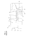
- Fig. 1 is a cross-sectional view of a known shroud 10 having a seal 12 that can be used with a known gas turbine 14.
- Known turbines 14 include seals 12, such as honeycomb and/or labyrinth seals, to reduce flow through a gap 16. More particularly, known labyrinth seals 12 include a tortuous path defined by longitudinally spaced-apart rows of labyrinth seal teeth 18 that seal against highpressure differentials that may be present in the turbine 14. However, the configurations of some known labyrinth seals 12 may induce fluid mixing losses and/or flow leakage losses of the gas on an exit side 20 of rotating buckets 22 that may adversely affect the efficiency of the turbine 14.
- flow paths of leakage flow 24 for some known seals 12 are sometimes not aligned with a subsequent nozzle 26, wherein misalignment increases the re-circulation of leakage flow 24 within the bucket exit side 20 subsequent labyrinth seal 12.
- the re-circulation of leakage flow 24 may mix with main flow 28, which may also adversely affect turbine efficiency.
- a shroud for a turbine includes a housing, a rotatable shaft, and a bucket extending outward therefrom.
- the shroud includes an alignment member which is coupled to the housing, wherein the alignment member includes a first end, a second end, and a body extending between the first and second ends.
- the second end includes an arcuate portion configured to facilitate fluid flow downstream from the bucket.
- the shroud further includes a seal coupled to the body to facilitate sealing a gap defined between the bucket and the body.
- a turbine in another aspect, includes a housing, a turbine shaft rotatably supported in the housing, and a plurality of turbine stages located along the turbine shaft and contained within the housing.
- Each turbine stage includes a rotor coupled to the turbine shaft, wherein the rotor includes a bucket radially extending outward therefrom.
- a shroud is coupled to the housing and includes a first end, a second end, and a body extending between the first and second ends.
- the second end includes an arcuate portion configured to facilitate leakage flow downstream from the bucket.
- the body further includes a first groove and a second groove.
- a seal is coupled to the first groove and the second groove to facilitate sealing a gap defined between the bucket and the body.
- a method of assembling a shroud to a turbine has a housing, a rotatable shaft and a bucket radially extending outward from the rotatable shaft.
- the method includes coupling a shroud to the housing and extending an arcuate portion of the shroud outward from the housing to facilitate fluid flow downstream from the bucket.
- the method further includes coupling a seal to the shroud to facilitate sealing a gap defined between the bucket and the shroud.
- Fig. 2 is a schematic view of a rotary machine 30, such as a gas turbine 32.
- Turbine 32 includes an intake section 34, a compressor section 36 that is downstream from intake section 34, a combustor section 38 downstream from compressor section 36, a turbine section 40 downstream from combustor section 38, and an exhaust section 42 downstream from turbine section 40.
- Turbine section 40 is coupled to compressor section 36 via a rotor assembly 44 that includes a shaft 46 that extends along a centerline axis 48.
- Combustor section 38 includes a plurality of combustor assemblies 50 that are each coupled in flow communication with the compressor section 36.
- a fuel nozzle assembly 52 is coupled to each combustor assembly 50.
- Turbine section 40 is rotatably coupled to compressor section 36 and to a load 54 such as, but not limited to, an electrical generator and/or a mechanical drive application.
- Combustor assembly 50 injects fuel, for example, natural gas and/or fuel oil, into the air flow, ignites the fuel-air mixture to expand the fuel-air mixture through combustion, and generates high temperature combustion gases. Combustion gases are discharged from combustor assembly 50 towards turbine section 40, wherein thermal energy in the gases is converted to mechanical rotational energy. Combustion gases impart rotational energy to turbine section 40 and to rotor assembly 44, which subsequently provides rotational power to compressor section 36.
- fuel for example, natural gas and/or fuel oil
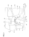
- Fig. 3 is a cross-sectional view of an exemplary shroud 56, rotor 58, and seal 60 used with turbine 32 (shown in Fig. 2 ).
- Shroud 56 is configured to mitigate leakage flow 62 such as, but not limited to, hot gas flow within turbine 32 and to mitigate leakage flow 62 mixing with main flow 64, for example, hot gas flow through turbine 32.
- a clearance gap 66 is defined between shroud 56 and tip of rotor 58, wherein seal 60 is configured to facilitate sealing gap 66 to reduce leakage flow 62 through gap 66.
- turbine 32 includes a diaphragm 68 having a radial outer portion 70, a radial inner portion 72, and a nozzle 74.
- Shroud 56 and radial outer portion 70 are coupled to a housing 76, while nozzle 74 is coupled to radial outer portion 70, and radial inner portion 72 is coupled to nozzle 74.
- Rotor 58 includes turbine buckets 78 that are coupled at their radially inner ends 80 to turbine wheels 82 extending radially outward from turbine shaft 46 such that buckets 78 are rotatable about an axis 84.
- Bucket 78 has a flow inlet side 86 and a flow outlet side 88, which is downstream of flow inlet side 86.
- Bucket 78 further includes a bucket tip 92, wherein bucket tip 92 includes a plurality of teeth 94 extending radially therefrom, within gap 66 and towards shroud 56.
- a set of stationary nozzles 74 and rotating buckets 78 form a stage 96 of turbine 32.
- turbine 32 includes a subsequent stage 98 having a subsequent radial outer portion 100 and a nozzle 102.
- Nozzle 102 includes an inlet side 104, an outlet side 106, and side wall 108. Side wall 108 is angled with respect to shroud 56.
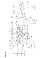
- Fig. 4 illustrates a cross-sectional view of shroud 56.
- Shroud 56 includes an alignment member 110 having a first end 112, a second end 114, and a body 116 extending between first end 112 and second end 114.
- Shroud 56 is sized and shaped to maintain gap 66 as minimally allowed between bucket teeth 94 and seal 60 to provide a tortuous path for leakage flow 62 from bucket inlet side 86 through gap 66 and into bucket outlet side 88.
- First end 112 includes a first substantially straight portion 118 and a second substantially straight portion 120.
- portions 118 and 120 are positioned substantially orthogonal to each other. Alternatively, any orientation of portions 118 and 120 may be used that enables turbine 32 to function as described herein.
- Second end 114 is configured to channel tip leakage flow 62 from gap 66, downstream from bucket 78, and towards nozzle side wall 108.
- second end 114 is sized and shaped to substantially match a flow profile of side wall 108 of nozzle 102 to facilitate alignment of leakage flow 62 towards sidewall 108 to minimize and/or eliminate re-circulation of leakage flow 62 into bucket outlet side 88 as compared to conventional turbines 14 (shown in Fig. 1 ).
- Second end 114 includes a substantially smooth profile 122 which is configured to direct leakage flow 62 toward side wall 10 to facilitate minimizing and/or eliminating sharp turns of leakage flow 62.
- second end 114 is configured to facilitate minimizing and/or eliminating mixing of leakage flow 62 with main flow 64.
- second end 114 includes a first substantially straight portion 124, a second substantially straight portion 126, and an arcuate portion 128 extending between portions 124 and 126.
- second end 114 may include any number of straight and arcuate portions to enable shroud 56 to function as described herein.
- arcuate portion 128 extends radially outward from housing 76. As illustrated, because arcuate portion 128 extends radially outward from housing 76, second substantially straight portion 126 is positioned at an angle 130 relative to first substantially straight portion 124 and in line to side wall 108 of subsequent nozzle 102. Moreover, in the exemplary embodiment, second substantially straight portion 126 is orientated at less than about 45° relative to first substantially straight portion 124. The orientation of first substantially straight portion 124, second substantially straight portion 126, and arcuate portion 128 facilitates leakage flow 62 downstream beyond bucket 78 and towards nozzle sidewall 108.
- arcuate portion 128 is configured to position second portion 126 in substantial alignment with angle of sidewall 108 to facilitate leakage flow 62 from gap 66, downstream of bucket 78 and toward nozzle 102. Any orientation of first and second portions 124 and 126 and arcuate portion 128 may be used to facilitate flow alignment with nozzle side wall 108, and enables turbine 32 to function as described herein. Moreover, because arcuate portion 128 is configured to direct leakage flow 62 toward side wall 108, arcuate portion 128 facilitates minimizing and/or eliminating re-circulation and mixing of leakage flow 62 with main flow 64.
- Arcuate portion 128 is sized and shaped to facilitate reducing and/or eliminating flow mixing losses and/or flow path losses through gap 66 as compared to conventional shrouds having substantially straight exit ends, which increases efficiencies of turbine operations. More particularly, arcuate portion 128 is configured to channel leakage flow 62 substantially uniform out of gap 66 and towards nozzle 102, and to facilitate smooth transition of leakage flow 62 in alignment with nozzle wall 108 towards nozzle 102. Moreover, the shape of arcuate portion 128 directs leakage flow 62 to minimize flow impact of leakage flow 62 toward side wall 108 against a nozzle arcuate surface 131. Reducing flow impact of leakage flow 62 facilitates reducing and/or eliminating oxidation of nozzle arcuate surface 131 and/or adverse heat effects on surface 131, to enhance increasing operating life of nozzle 102.
- alignment member 110 also includes a first groove 132 and a second groove 134.
- First groove 132 and second groove 134 are in flow communication with gap 66 and facilitate coupling seal 60 to body 116.
- First groove 132 is defined by opposing side walls 136 and 138 and an end wall 140 that extends between side walls 136 and 138. End wall 140 has a first length 142.
- side walls 136 and 138 are angled towards body 116 to facilitate reducing flow leakage and flow losses across gap 66.
- side walls 136 and 138 may extend orthogonally (not shown) to body 116.
- Second groove 134 is defined by opposing side walls 144 and 146 and an end wall 148 that extends between side walls 144 and 146.
- End wall 148 has a second length 149.
- End wall length 142 is longer than end wall length 149.
- a shortened second groove 134 facilitates channeling leakage flow 62 out of gap 66 to facilitate reducing flow leakages and losses of fluid flow 62 downstream towards each subsequent nozzle 102 and subsequent bucket (not shown).
- lengths 142 and 149 can have any length that enables seal 60 to function as described herein.
- sidewalls 144 and 146 are angled towards body 116 to facilitate reducing flow leakages and losses across gap 66.
- side walls 144 and 146 may extend orthogonally (not shown) to body 116.
- Seal 60 extends between bucket 78 and member 110.
- seal 60 includes a honeycomb seal 150 that is coupled to body 116 and that is mounted within at least first groove 132 and second groove 134.
- Honeycomb seal 150 is fabricated from thin corrugated strips 152 that are mated together in a honeycomb configuration to form cells 154.
- cells 154 are each hexagonal.
- cells 154 can have any other shape, including circular, triangular, and/or rectangular, that enables seal 60 to function as described herein.
- seal 60 can include other seals such as, but not limited to, brush seals (not shown).
- Seal 60 also includes at least one seal tooth 156 that extends from body 116 into gap 66. Tooth 156 defines a tortuous path with teeth 94 that facilitates mitigating leakage flow 62 through gap 66.
- seal tooth 156 is positioned between grooves 132 and 134.
- a first tooth 158 of teeth 94 is spaced a first distance 160 from seal tooth 156 and a second tooth 162 of teeth 94 is spaced at a second distance 164 from seal tooth 156.
- first distance 160 is longer than second distance 164.
- a shortened second distance 164 facilitates reducing flow leakages and flow losses of leakage flow 62 towards arcuate portion 128.
- distances 160 and 164 can have any length that enables seal 60 to function as described herein.
- first end 112 and second end 114 of alignment member 110 minimize and/or eliminate additional seal teeth on opposite sides of tooth 156.
- seal tooth 156 is thicker than conventional teeth 18 (shown in Fig. 1 ) to better withstand oxidation effects as compared to conventional teeth 18 to reduce maintenance and replacement costs for turbine 32.
- alignment member 110 may include multiple teeth 156 to enable shroud 56 to function as described herein.
- Fig. 5 is a side view of another exemplary end 168 of shroud 166 that may be used with diaphragm 68 shown in Fig. 4 .
- End 168 includes an arcuate portion 170 extending between an end 172 and an end 174.
- Arcuate portion 170 is sized and shaped to direct leakage flow 62 downstream of bucket 78 and towards nozzle sidewall 108. More particularly, arcuate portion 170 is configured to facilitate minimizing and/or eliminating re-circulation of leakage flow 62 into bucket outlet side 88, which minimizes and/or eliminates mixing of leakage flow 62 with main flow 64.
- end 168 is sized and shaped to reduce leakage losses of leakage flow 62 within gap 66 (shown in Fig. 4 ).
- Fig. 6 is a side view of another exemplary end 178 of shroud 176 that may be used with the diaphragm 68 shown in Fig. 4 . Unless otherwise specified, similar components are labeled in Fig. 6 with the same reference numerals used in Figs. 3 and 4 .
- End 178 includes an arcuate portion 180, a straight portion 182, and an arcuate portion 184. Portions 180, 182, and 184 are sized and shaped to direct leakage flow 62 downstream from bucket 78 and towards nozzle sidewall 108.
- end 178 is configured to facilitate minimizing and/or eliminating re-circulation of leakage flow 62 into bucket outlet side 88, which minimizes and/or eliminates mixing of leakage flow 62 with main flow 64.
- portions 180, 182, and 184 are sized and shaped to reduce leakage losses of leakage flow 62 within gap 66 (shown in Fig. 4 ).
- Fig. 7 is a side view of another exemplary end 188 of shroud 186 that may be used with the diaphragm 68 shown in Fig. 4 .
- End 188 includes a straight portion 190 and an arcuate portion 192.
- Portions 190 and 192 are sized and shaped to direct leakage flow 62 downstream from bucket 78 and towards nozzle side wall 108. More particularly, end 188 is configured to facilitate minimizing and/or eliminating re-circulation of leakage flow 62 into bucket outlet side 88, which minimizes and/or eliminates mixing of leakage flow 62 with main flow 64.
- portions 190 and 192 are sized and shaped to reduce leakage losses of leakage flow 62 within gap 66 (shown in Fig. 4 ).
- Fig. 8 is a side view of another exemplary end 196 of shroud 194 that may be used with the diaphragm 68 shown in Fig. 4 .
- End 196 includes an arcuate portion 198 and a straight portion 200.
- Portions 198 and 200 are sized and shaped to direct leakage flow 62 downstream from bucket 78 and towards nozzle sidewall 108. More particularly, end 196 is configured to facilitate minimizing and/or eliminating re-circulation of leakage flow 62 into bucket outlet side 88, which minimizes and/or eliminates mixing of leakage flow 62 with main flow 64.
- portions 198 and 200 are sized and shaped to reduce leakage losses of leakage flow 62 within gap 66 (shown in Fig. 4 ).
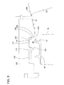
- Fig. 9 is a cross-sectional view of another exemplary shroud 202 that may be used with diaphragm 68 (shown in Fig. 4 ). Unless otherwise specified, similar components are labeled in Fig. 9 with the same reference numerals used in Figs. 3 and 4 .
- second groove 134 is defined by opposing side walls 144 and 146, and end wall 148. More particularly, side wall 144 is oriented at a first angle 204 relative to end wall 148. Opposite side wall 146 includes a substantially straight portion 206 and an angled portion 208 that is oriented at a second angle 210 relative to end wall 148. In the exemplary embodiment, first angle 204 is larger than second angle 210.
- Straight portion 206, angled portion 208 and angles 204 and 210 are sized, shaped, and orientated to facilitate reducing and/or eliminating reducing flow mixing losses and flow path losses for fluid flow 62 as compared to conventional shrouds. Moreover, straight portion 206 and angled portion 208 facilitate minimizing and/or eliminating re-circulation of leakage flow 62 into bucket outlet side 88, which minimizes and/or eliminates mixing of leakage flow 62 with main flow 64.
- Fig. 10 is a flowchart illustrating an exemplary method 300 of assembling a turbine, for example turbine 32 (shown in Fig. 2 ).
- turbine includes a housing, a rotatable shaft, and a rotor coupled to shaft.
- the rotor includes a bucket that extends radially outward from the shaft.
- Method 300 includes coupling 310 a shroud, for example shroud 56 (shown in Fig. 4 ), to the housing.
- the shroud includes an alignment member having a first end, a second end, and a body extending between the first and second ends, such as alignment member 110, first end 112, second end 114, and body 116 (all shown in Fig. 4 ).
- the second end includes an arcuate portion, for example arcuate portion 128 (shown in Fig. 4 ).
- the body includes a first groove and a second groove, such as first groove 132 and second groove 134 (shown in Fig. 4 ).
- Method 300 includes extending 320 the arcuate portion relative to and beyond the bucket to facilitate fluid flow downstream to a subsequent nozzle.
- orientating the arcuate portion includes extending the arcuate portion radially outward from the housing.
- a seal such as seal 60 (shown in Fig. 4 ), is coupled 330 to the shroud to facilitate sealing a gap defined between the bucket and the shroud.
- the seal is coupled to the body between the first and second grooves.
- fluid flow 64 is channeled through nozzle 74 towards buckets 78, which causes buckets 78 to rotate with turbine shaft 46 to induce work output by shaft 46.
- a portion of leakage flow 62 is channeled from inlet side 86 of bucket 78 into gap 66.
- Bucket tip 92 shown in Fig. 3
- teeth 94 and shroud seal 60 shown in Fig, 4
- mitigating leakage losses from leakage flow 62 such as, for example, hot gas flow through gap 66.
- Leakage flow 62 is leaked through labyrinth paths formed by bucket teeth 94, honeycomb seal 150, and seal tooth 156 (shown in Fig, 4 ).
- Fluid flow 62 is then channeled towards arcuate portion 128 of shroud 56.
- Arcuate portion 128 facilitates directing leakage flow 62 smoothly towards nozzle side wall 108 without any sharp turnings and reverse flow and/or recirculated flow downstream from bucket 78.
- Each subsequent nozzle 102 directs fluid flow 64 downstream towards another bucket (not shown) for rotation.
- An arcuate portion of the shroud is sized and shaped to align and channel gas flow out of a clearance gap defined between the shroud and a rotor and towards a subsequent nozzle.
- the arcuate portion is sized and shaped to facilitate reducing flow leakages and losses of gas flow from the bucket.
Landscapes
- Engineering & Computer Science (AREA)
- Mechanical Engineering (AREA)
- General Engineering & Computer Science (AREA)
- Physics & Mathematics (AREA)
- Fluid Mechanics (AREA)
- Turbine Rotor Nozzle Sealing (AREA)
Abstract
Description
- The present invention relates generally to rotary machines, and more particularly, to methods and apparatus to facilitate fluid flow within the rotary machine by reducing fluid leakage losses and fluid mixing losses within the rotary machine.
- Rotary machines, such as gas turbines, are used to generate power for electric generators. A gas turbine has a gas path which typically includes, in serial-flow relationship, an air intake (or inlet), a compressor, a combustor, a turbine, and a gas outlet (or exhaust nozzle). Compressor and turbine sections include at least one row of circumferentially spaced rotating buckets or blades positioned within a housing.
- Turbine efficiency depends at least in part on a radial clearance or gap between tips of the rotating buckets and a shroud coupled to the surrounding housing. The clearance is needed to avoid contact or rubbing between the bucket tips and the shroud which results in a design limitation for the size of the clearance. If the clearance is too large, enhanced gas flow may leak through the clearance gaps, thus decreasing the turbine's efficiency. Leakage flow, either out of the flow path or into the flow path, from an area of higher pressure to an area of lower pressure, is generally undesirable. If the clearance is too small, the rotor bucket tips may undesirably contact/rub the surrounding shroud during certain turbine operating conditions, which may also decrease the turbine's efficiency. To accommodate for the design limitation of the clearance gap, some known turbines utilize honeycomb and/or labyrinth seals with the shroud and/or bucket to reduce leakage flow through the clearance gap.
-
Fig. 1 is a cross-sectional view of a knownshroud 10 having aseal 12 that can be used with a knowngas turbine 14.Known turbines 14 includeseals 12, such as honeycomb and/or labyrinth seals, to reduce flow through agap 16. More particularly, knownlabyrinth seals 12 include a tortuous path defined by longitudinally spaced-apart rows oflabyrinth seal teeth 18 that seal against highpressure differentials that may be present in theturbine 14. However, the configurations of some knownlabyrinth seals 12 may induce fluid mixing losses and/or flow leakage losses of the gas on anexit side 20 of rotatingbuckets 22 that may adversely affect the efficiency of theturbine 14. More particularly, flow paths ofleakage flow 24 for some knownseals 12 are sometimes not aligned with asubsequent nozzle 26, wherein misalignment increases the re-circulation ofleakage flow 24 within thebucket exit side 20subsequent labyrinth seal 12. The re-circulation ofleakage flow 24 may mix withmain flow 28, which may also adversely affect turbine efficiency. - In one aspect, a shroud for a turbine is provided. The turbine includes a housing, a rotatable shaft, and a bucket extending outward therefrom. The shroud includes an alignment member which is coupled to the housing, wherein the alignment member includes a first end, a second end, and a body extending between the first and second ends. The second end includes an arcuate portion configured to facilitate fluid flow downstream from the bucket. The shroud further includes a seal coupled to the body to facilitate sealing a gap defined between the bucket and the body.
- In another aspect, a turbine is provided. The turbine includes a housing, a turbine shaft rotatably supported in the housing, and a plurality of turbine stages located along the turbine shaft and contained within the housing. Each turbine stage includes a rotor coupled to the turbine shaft, wherein the rotor includes a bucket radially extending outward therefrom. A shroud is coupled to the housing and includes a first end, a second end, and a body extending between the first and second ends. The second end includes an arcuate portion configured to facilitate leakage flow downstream from the bucket. The body further includes a first groove and a second groove. A seal is coupled to the first groove and the second groove to facilitate sealing a gap defined between the bucket and the body.
- In a further aspect, a method of assembling a shroud to a turbine is provided. The turbine has a housing, a rotatable shaft and a bucket radially extending outward from the rotatable shaft. The method includes coupling a shroud to the housing and extending an arcuate portion of the shroud outward from the housing to facilitate fluid flow downstream from the bucket. The method further includes coupling a seal to the shroud to facilitate sealing a gap defined between the bucket and the shroud.
-
Fig. 1 is a cross-sectional view of a known shroud used with a known gas turbine. -
Fig. 2 is a schematic view of a rotary machine. -
Fig. 3 is a cross-sectional view of an exemplary diaphragm, a shroud, a rotor, and a seal that may be used with the rotary machine shown inFig. 2 . -
Fig. 4 is a cross-sectional view of the exemplary shroud that may be used with the diaphragm shown inFig. 3 . -
Fig. 5 is a cross-sectional view of another exemplary shroud that may be used with the diaphragm shown inFig. 3 . -
Fig. 6 is a cross-sectional view of another exemplary shroud that may be used with the diaphragm shown inFig. 3 . -
Fig. 7 is a cross-sectional view of another exemplary shroud that may be used with the diaphragm shown inFig. 3 . -
Fig. 8 is a cross-sectional view of another exemplary shroud that may be used with the diaphragm shown inFig. 3 . -
Fig. 9 is a cross-sectional view of another exemplary shroud that may be used with the shroud shown inFig. 3 . -
Fig. 10 is a flowchart of an exemplary method of assembling a turbine. -
Fig. 2 is a schematic view of arotary machine 30, such as agas turbine 32.Turbine 32 includes anintake section 34, acompressor section 36 that is downstream fromintake section 34, acombustor section 38 downstream fromcompressor section 36, aturbine section 40 downstream fromcombustor section 38, and anexhaust section 42 downstream fromturbine section 40.Turbine section 40 is coupled tocompressor section 36 via arotor assembly 44 that includes ashaft 46 that extends along acenterline axis 48.Combustor section 38 includes a plurality ofcombustor assemblies 50 that are each coupled in flow communication with thecompressor section 36. Afuel nozzle assembly 52 is coupled to eachcombustor assembly 50.Turbine section 40 is rotatably coupled tocompressor section 36 and to aload 54 such as, but not limited to, an electrical generator and/or a mechanical drive application. - During operation, air flows through
compressor section 36 and compressed air is discharged intocombustor section 38.Combustor assembly 50 injects fuel, for example, natural gas and/or fuel oil, into the air flow, ignites the fuel-air mixture to expand the fuel-air mixture through combustion, and generates high temperature combustion gases. Combustion gases are discharged fromcombustor assembly 50 towardsturbine section 40, wherein thermal energy in the gases is converted to mechanical rotational energy. Combustion gases impart rotational energy toturbine section 40 and torotor assembly 44, which subsequently provides rotational power tocompressor section 36. -
Fig. 3 is a cross-sectional view of anexemplary shroud 56,rotor 58, andseal 60 used with turbine 32 (shown inFig. 2 ). Shroud 56 is configured to mitigateleakage flow 62 such as, but not limited to, hot gas flow withinturbine 32 and to mitigateleakage flow 62 mixing withmain flow 64, for example, hot gas flow throughturbine 32. Aclearance gap 66 is defined betweenshroud 56 and tip ofrotor 58, whereinseal 60 is configured to facilitatesealing gap 66 to reduceleakage flow 62 throughgap 66. In the exemplary embodiment,turbine 32 includes adiaphragm 68 having a radialouter portion 70, a radialinner portion 72, and anozzle 74. Shroud 56 and radialouter portion 70 are coupled to ahousing 76, whilenozzle 74 is coupled to radialouter portion 70, and radialinner portion 72 is coupled tonozzle 74. -
Rotor 58 includesturbine buckets 78 that are coupled at their radiallyinner ends 80 toturbine wheels 82 extending radially outward fromturbine shaft 46 such thatbuckets 78 are rotatable about anaxis 84.Bucket 78 has aflow inlet side 86 and aflow outlet side 88, which is downstream offlow inlet side 86.Bucket 78 further includes abucket tip 92, whereinbucket tip 92 includes a plurality ofteeth 94 extending radially therefrom, withingap 66 and towardsshroud 56. A set ofstationary nozzles 74 and rotatingbuckets 78 form astage 96 ofturbine 32. Moreover,turbine 32 includes asubsequent stage 98 having a subsequent radialouter portion 100 and anozzle 102.Nozzle 102 includes aninlet side 104, anoutlet side 106, andside wall 108.Side wall 108 is angled with respect toshroud 56. -
Fig. 4 illustrates a cross-sectional view ofshroud 56.Shroud 56 includes analignment member 110 having afirst end 112, asecond end 114, and abody 116 extending betweenfirst end 112 andsecond end 114.Shroud 56 is sized and shaped to maintaingap 66 as minimally allowed betweenbucket teeth 94 and seal 60 to provide a tortuous path forleakage flow 62 frombucket inlet side 86 throughgap 66 and intobucket outlet side 88.First end 112 includes a first substantiallystraight portion 118 and a second substantiallystraight portion 120. In the exemplary embodiment,portions portions turbine 32 to function as described herein. -
Second end 114 is configured to channel tip leakage flow 62 fromgap 66, downstream frombucket 78, and towardsnozzle side wall 108. In the exemplary embodiment,second end 114 is sized and shaped to substantially match a flow profile ofside wall 108 ofnozzle 102 to facilitate alignment ofleakage flow 62 towardssidewall 108 to minimize and/or eliminate re-circulation ofleakage flow 62 intobucket outlet side 88 as compared to conventional turbines 14 (shown inFig. 1 ).Second end 114 includes a substantiallysmooth profile 122 which is configured to directleakage flow 62 towardside wall 10 to facilitate minimizing and/or eliminating sharp turns ofleakage flow 62. Moreover,second end 114 is configured to facilitate minimizing and/or eliminating mixing ofleakage flow 62 withmain flow 64. In the exemplary embodiment,second end 114 includes a first substantiallystraight portion 124, a second substantiallystraight portion 126, and anarcuate portion 128 extending betweenportions second end 114 may include any number of straight and arcuate portions to enableshroud 56 to function as described herein. - In the exemplary embodiment,
arcuate portion 128 extends radially outward fromhousing 76. As illustrated, becausearcuate portion 128 extends radially outward fromhousing 76, second substantiallystraight portion 126 is positioned at anangle 130 relative to first substantiallystraight portion 124 and in line toside wall 108 ofsubsequent nozzle 102. Moreover, in the exemplary embodiment, second substantiallystraight portion 126 is orientated at less than about 45° relative to first substantiallystraight portion 124. The orientation of first substantiallystraight portion 124, second substantiallystraight portion 126, andarcuate portion 128 facilitatesleakage flow 62 downstream beyondbucket 78 and towardsnozzle sidewall 108. More particularly,arcuate portion 128 is configured to positionsecond portion 126 in substantial alignment with angle ofsidewall 108 to facilitateleakage flow 62 fromgap 66, downstream ofbucket 78 and towardnozzle 102. Any orientation of first andsecond portions arcuate portion 128 may be used to facilitate flow alignment withnozzle side wall 108, and enablesturbine 32 to function as described herein. Moreover, becausearcuate portion 128 is configured to directleakage flow 62 towardside wall 108,arcuate portion 128 facilitates minimizing and/or eliminating re-circulation and mixing ofleakage flow 62 withmain flow 64. -
Arcuate portion 128 is sized and shaped to facilitate reducing and/or eliminating flow mixing losses and/or flow path losses throughgap 66 as compared to conventional shrouds having substantially straight exit ends, which increases efficiencies of turbine operations. More particularly,arcuate portion 128 is configured to channelleakage flow 62 substantially uniform out ofgap 66 and towardsnozzle 102, and to facilitate smooth transition ofleakage flow 62 in alignment withnozzle wall 108 towardsnozzle 102. Moreover, the shape ofarcuate portion 128 directsleakage flow 62 to minimize flow impact ofleakage flow 62 towardside wall 108 against a nozzlearcuate surface 131. Reducing flow impact ofleakage flow 62 facilitates reducing and/or eliminating oxidation of nozzlearcuate surface 131 and/or adverse heat effects onsurface 131, to enhance increasing operating life ofnozzle 102. - In the exemplary embodiment,
alignment member 110 also includes afirst groove 132 and asecond groove 134.First groove 132 andsecond groove 134 are in flow communication withgap 66 and facilitatecoupling seal 60 tobody 116.First groove 132 is defined by opposingside walls end wall 140 that extends betweenside walls End wall 140 has afirst length 142. In the exemplary embodiment,side walls body 116 to facilitate reducing flow leakage and flow losses acrossgap 66. Alternatively,side walls body 116. -
Second groove 134 is defined by opposingside walls end wall 148 that extends betweenside walls End wall 148 has asecond length 149.End wall length 142 is longer thanend wall length 149. A shortenedsecond groove 134 facilitates channelingleakage flow 62 out ofgap 66 to facilitate reducing flow leakages and losses offluid flow 62 downstream towards eachsubsequent nozzle 102 and subsequent bucket (not shown). Alternatively,lengths seal 60 to function as described herein. In the exemplary embodiment, sidewalls 144 and 146 are angled towardsbody 116 to facilitate reducing flow leakages and losses acrossgap 66. Alternatively,side walls body 116. -
Seal 60 extends betweenbucket 78 andmember 110. In the exemplary embodiment, seal 60 includes ahoneycomb seal 150 that is coupled tobody 116 and that is mounted within at leastfirst groove 132 andsecond groove 134.Honeycomb seal 150 is fabricated from thincorrugated strips 152 that are mated together in a honeycomb configuration to formcells 154. In the exemplary embodiment,cells 154 are each hexagonal. Alternatively,cells 154 can have any other shape, including circular, triangular, and/or rectangular, that enablesseal 60 to function as described herein. Additionally, or alternatively, seal 60 can include other seals such as, but not limited to, brush seals (not shown). -
Seal 60 also includes at least oneseal tooth 156 that extends frombody 116 intogap 66.Tooth 156 defines a tortuous path withteeth 94 that facilitates mitigatingleakage flow 62 throughgap 66. In the exemplary embodiment,seal tooth 156 is positioned betweengrooves first tooth 158 ofteeth 94 is spaced afirst distance 160 fromseal tooth 156 and asecond tooth 162 ofteeth 94 is spaced at asecond distance 164 fromseal tooth 156. In the exemplary embodiment,first distance 160 is longer thansecond distance 164. A shortenedsecond distance 164 facilitates reducing flow leakages and flow losses ofleakage flow 62 towardsarcuate portion 128. Alternatively, distances 160 and 164 can have any length that enablesseal 60 to function as described herein. In the exemplary embodiment,first end 112 andsecond end 114 ofalignment member 110 minimize and/or eliminate additional seal teeth on opposite sides oftooth 156. Moreover,seal tooth 156 is thicker than conventional teeth 18 (shown inFig. 1 ) to better withstand oxidation effects as compared toconventional teeth 18 to reduce maintenance and replacement costs forturbine 32. Alternatively,alignment member 110 may includemultiple teeth 156 to enableshroud 56 to function as described herein. -
Fig. 5 is a side view of anotherexemplary end 168 ofshroud 166 that may be used withdiaphragm 68 shown inFig. 4 . Unless otherwise specified, similar components are labeled inFig. 5 with the same reference numerals used inFigs. 3 and4 .End 168 includes anarcuate portion 170 extending between anend 172 and anend 174.Arcuate portion 170 is sized and shaped todirect leakage flow 62 downstream ofbucket 78 and towardsnozzle sidewall 108. More particularly,arcuate portion 170 is configured to facilitate minimizing and/or eliminating re-circulation ofleakage flow 62 intobucket outlet side 88, which minimizes and/or eliminates mixing ofleakage flow 62 withmain flow 64. Moreover, end 168 is sized and shaped to reduce leakage losses ofleakage flow 62 within gap 66 (shown inFig. 4 ). -
Fig. 6 is a side view of anotherexemplary end 178 ofshroud 176 that may be used with thediaphragm 68 shown inFig. 4 . Unless otherwise specified, similar components are labeled inFig. 6 with the same reference numerals used inFigs. 3 and4 .End 178 includes anarcuate portion 180, astraight portion 182, and anarcuate portion 184.Portions direct leakage flow 62 downstream frombucket 78 and towardsnozzle sidewall 108. More particularly, end 178 is configured to facilitate minimizing and/or eliminating re-circulation ofleakage flow 62 intobucket outlet side 88, which minimizes and/or eliminates mixing ofleakage flow 62 withmain flow 64. Moreover,portions leakage flow 62 within gap 66 (shown inFig. 4 ). -
Fig. 7 is a side view of anotherexemplary end 188 ofshroud 186 that may be used with thediaphragm 68 shown inFig. 4 . Unless otherwise specified, similar components are labeled inFig. 7 with the same reference numerals used inFigs. 3 and4 .End 188 includes astraight portion 190 and anarcuate portion 192.Portions direct leakage flow 62 downstream frombucket 78 and towardsnozzle side wall 108. More particularly, end 188 is configured to facilitate minimizing and/or eliminating re-circulation ofleakage flow 62 intobucket outlet side 88, which minimizes and/or eliminates mixing ofleakage flow 62 withmain flow 64. Moreover,portions leakage flow 62 within gap 66 (shown inFig. 4 ). -
Fig. 8 is a side view of anotherexemplary end 196 ofshroud 194 that may be used with thediaphragm 68 shown inFig. 4 . Unless otherwise specified, similar components are labeled inFig. 8 with the same reference numerals used inFigs. 3 and4 .End 196 includes anarcuate portion 198 and astraight portion 200.Portions direct leakage flow 62 downstream frombucket 78 and towardsnozzle sidewall 108. More particularly, end 196 is configured to facilitate minimizing and/or eliminating re-circulation ofleakage flow 62 intobucket outlet side 88, which minimizes and/or eliminates mixing ofleakage flow 62 withmain flow 64. Moreover,portions leakage flow 62 within gap 66 (shown inFig. 4 ). -
Fig. 9 is a cross-sectional view of anotherexemplary shroud 202 that may be used with diaphragm 68 (shown inFig. 4 ). Unless otherwise specified, similar components are labeled inFig. 9 with the same reference numerals used inFigs. 3 and4 . In the exemplary embodiment,second groove 134 is defined by opposingside walls wall 148. More particularly,side wall 144 is oriented at afirst angle 204 relative to endwall 148. Oppositeside wall 146 includes a substantiallystraight portion 206 and anangled portion 208 that is oriented at asecond angle 210 relative to endwall 148. In the exemplary embodiment,first angle 204 is larger thansecond angle 210.Straight portion 206,angled portion 208 andangles fluid flow 62 as compared to conventional shrouds. Moreover,straight portion 206 andangled portion 208 facilitate minimizing and/or eliminating re-circulation ofleakage flow 62 intobucket outlet side 88, which minimizes and/or eliminates mixing ofleakage flow 62 withmain flow 64. -
Fig. 10 is a flowchart illustrating anexemplary method 300 of assembling a turbine, for example turbine 32 (shown inFig. 2 ). In theexemplary method 300, turbine includes a housing, a rotatable shaft, and a rotor coupled to shaft. The rotor includes a bucket that extends radially outward from the shaft.Method 300 includes coupling 310 a shroud, for example shroud 56 (shown inFig. 4 ), to the housing. The shroud includes an alignment member having a first end, a second end, and a body extending between the first and second ends, such asalignment member 110,first end 112,second end 114, and body 116 (all shown inFig. 4 ). The second end includes an arcuate portion, for example arcuate portion 128 (shown inFig. 4 ). The body includes a first groove and a second groove, such asfirst groove 132 and second groove 134 (shown inFig. 4 ). -
Method 300 includes extending 320 the arcuate portion relative to and beyond the bucket to facilitate fluid flow downstream to a subsequent nozzle. In the exemplary embodiment, orientating the arcuate portion includes extending the arcuate portion radially outward from the housing. A seal, such as seal 60 (shown inFig. 4 ), is coupled 330 to the shroud to facilitate sealing a gap defined between the bucket and the shroud. In the exemplary embodiment, the seal is coupled to the body between the first and second grooves. - During an exemplary operation of
turbine 32,fluid flow 64 is channeled throughnozzle 74 towardsbuckets 78, which causesbuckets 78 to rotate withturbine shaft 46 to induce work output byshaft 46. A portion ofleakage flow 62 is channeled frominlet side 86 ofbucket 78 intogap 66. Bucket tip 92 (shown inFig. 3 ) withteeth 94 and shroud seal 60 (shown inFig, 4 ) facilitates mitigating leakage losses fromleakage flow 62 such as, for example, hot gas flow throughgap 66.Leakage flow 62 is leaked through labyrinth paths formed bybucket teeth 94,honeycomb seal 150, and seal tooth 156 (shown inFig, 4 ).Fluid flow 62 is then channeled towardsarcuate portion 128 ofshroud 56.Arcuate portion 128 facilitates directingleakage flow 62 smoothly towardsnozzle side wall 108 without any sharp turnings and reverse flow and/or recirculated flow downstream frombucket 78. Eachsubsequent nozzle 102 directsfluid flow 64 downstream towards another bucket (not shown) for rotation. - The embodiments described herein enhance the efficiency, reliability, and reduced maintenance costs and outages of the associated turbine as compared to conventional shrouds. An arcuate portion of the shroud is sized and shaped to align and channel gas flow out of a clearance gap defined between the shroud and a rotor and towards a subsequent nozzle. The arcuate portion is sized and shaped to facilitate reducing flow leakages and losses of gas flow from the bucket.
- Although the embodiments are herein described and illustrated in association with a turbine for a gas turbine, it should be understood that the present invention may be used for controlling any fluid between any generally high pressure area and any generally low pressure area within any rotary machine. Accordingly, practice of the exemplary embodiments is not limited to gas turbines.
- Exemplary embodiments of systems and methods for using a shroud are described herein in detail. The systems and methods are not limited to the specific embodiments described herein, but rather, components of systems and/or steps of the method may be utilized independently and separately from other components and/or steps described herein. Each component and each assembly step may also be used in combination with other components and/or assembly steps. Although specific features of various embodiments may be shown in some drawings and not in others, this is for convenience only. Any feature of a drawing may be referenced and/or claimed in combination with any feature of any other drawing.
- This written description uses examples to disclose the invention, including the best mode, and also to enable any person skilled in the art to practice the invention, including making and using any devices or systems and performing any incorporated methods. The patentable scope of the invention is defined by the claims, and may include other examples that occur to those skilled in the art. Such other examples are intended to be within the scope of the claims if they have structural elements that do not differ from the literal language of the claims, or if they include equivalent structural elements with insubstantial differences from the literal languages of the claims.
- Various aspects and embodiments of the present invention are defined by the following numbered clauses:
- 1. A shroud for use with a turbine including a housing, a rotatable shaft and a bucket extending outward therefrom, said shroud comprising:
- an alignment member coupled to the housing and comprising a first end, a second end, and a body extending between said first and said second ends, said second end comprises an arcuate portion configured to facilitate leakage flow downstream from the bucket; and
- a seal coupled to said body to facilitate sealing a gap defined between the bucket and said body.
- 2. The shroud of Clause 1, wherein said arcuate surface extends radially outward from the housing.
- 3. The shroud of Clause 1 or Clause 2, wherein said second end comprises a pair of substantially straight portions.
- 4. The shroud of any preceding Clause, wherein said arcuate portion extends between said pair of substantially straight portions.
- 5. The shroud of any preceding Clause, wherein a first of said substantially straight portions is oriented obliquely relative to a second of said substantially straight portions.
- 6. The shroud of any preceding Clause, wherein said second end comprises a substantially straight portion that extends between said first end and said arcuate portion.
- 7. The shroud of any preceding Clause, wherein said second end comprises a substantially straight portion and said arcuate portion extends between said first end and said substantially straight portion.
- 8. The shroud of any preceding Clause, wherein said body comprises a first groove and a second groove defined therein such that said first groove has a first length and said second groove has a second length that is longer than said first length.
- 9. The shroud of any preceding Clause, wherein said second groove comprises a first angled side oriented at a first angle with respect to said body and a second angled side oriented at a second angle with respect to said body, said first angle is larger than said second angle.
- 10. The shroud of any preceding Clause, wherein said second end is configured in fluid flow alignment with a of nozzle of the turbine.
- 11. A turbine comprising:
- a housing;
- a turbine shaft rotatably supported in said housing; and
- a plurality of turbine stages located along said turbine shaft and contained within said housing, each turbine stage comprising:
- a rotor coupled to said turbine shaft, said rotor comprising a bucket extending radially outward therefrom;
- a shroud coupled to said housing and comprising a first end, a second end, and a body extending between said first and second ends, said second end comprises an arcuate portion configured to facilitate leakage flow downstream from said bucket towards nozzle, said body comprises a first groove and a second groove; and
- a seal coupled to said first groove and said second groove to facilitate sealing a gap defined between said bucket and said body.
- 12. The turbine of any preceding Clause, wherein said second end comprises a pair of substantially straight portions.
- 13. The turbine of any preceding Clause, wherein said arcuate portion extends between said pair of substantially straight portions.
- 14. The turbine of any preceding Clause, wherein a first of substantially straight portions is angled less than about 45° to a second of substantially straight portions.
- 15. The turbine of any preceding Clause, wherein at least one of said arcuate portion and pair of substantially straight portions are in flow alignment with a nozzle wall of a subsequent stage of said plurality of stages to facilitate alignment of leakage flow toward said nozzle wall.
- 16. The turbine of any preceding Clause, wherein said seal comprises a seal tooth between said first groove and said second groove and extending radially into the gap.
- 17. The turbine of any preceding Clause, wherein said bucket includes a first radial tooth and a second radial tooth, said first radial tooth is spaced from said seal tooth at a first distance and said second radial tooth is spaced from said second end a second distance, said first distance is longer than said second distance.
- 18. A method of assembling a turbine including a housing, a rotatable shaft, and a bucket extending radially outward from the rotatable shaft, said method comprising:
- coupling a shroud to the housing;
- extending an arcuate surface of the shroud outward from the housing to facilitate leakage flow downstream from the bucket; and
- coupling a seal to the shroud to facilitate sealing a gap defined between the bucket and the shroud.
- 19. The method of any preceding Clause, wherein extending the arcuate surface comprises positioning the arcuate surface to extend radially from the housing.
- 20. The method of any preceding Clause, wherein coupling the seal comprises coupling the seal to a first groove and a second groove of the shroud.
Claims (15)
- A shroud (56) for use with a turbine including a housing (76), a rotatable shaft (46) and a bucket (78) extending outward therefrom, said shroud comprising:an alignment member coupled to the housing (76) and comprising a first end (112), a second end (114), and a body (116) extending between said first and said second ends, said second end comprises an arcuate portion (128) configured to facilitate leakage flow downstream from the bucket (78); anda seal (60) coupled to said body (116) to facilitate sealing a gap (66) defined between the bucket (78) and said body (116).
- The shroud of Claim 1, wherein said arcuate surface extends radially outward from the housing.
- The shroud of Claim 1 or Claim 2, wherein said second end (114) comprises a pair of substantially straight portions.
- The shroud of any preceding Claim, wherein said arcuate portion extends between said pair of substantially straight portions.
- The shroud of any preceding Claim, wherein a first of said substantially straight portions is oriented obliquely relative to a second of said substantially straight portions.
- The shroud of any preceding Claim, wherein said second end comprises a substantially straight portion that extends between said first end and said arcuate portion.
- The shroud of any preceding Claim, wherein said second end comprises a substantially straight portion and said arcuate portion extends between said first end and said substantially straight portion.
- The shroud of any preceding Claim, wherein said body comprises a first groove and a second groove defined therein such that said first groove has a first length and said second groove has a second length that is longer than said first length.
- The shroud of any preceding Claim, wherein said second groove comprises a first angled side oriented at a first angle with respect to said body and a second angled side oriented at a second angle with respect to said body, said first angle is larger than said second angle.
- The shroud of any preceding Claim, wherein said second end is configured in fluid flow alignment with a of nozzle of the turbine.
- A turbine comprising:a housing;a turbine shaft rotatably supported in said housing; anda plurality of turbine stages located along said turbine shaft and contained within said housing, each turbine stage comprising: anda rotor coupled to said turbine shaft, said rotor comprising a bucket extending radially outward therefrom;a shroud according to any preceding Claim coupled to said housing
- A turbine comprising:a housing;a turbine shaft rotatably supported in said housing; anda plurality of turbine stages located along said turbine shaft and contained within said housing, each turbine stage comprising:a rotor coupled to said turbine shaft, said rotor comprising a bucket extending radially outward therefrom;a shroud coupled to said housing and comprising a first end, a second end, and a body extending between said first and second ends, said second end comprises an arcuate portion configured to facilitate leakage flow downstream from said bucket towards nozzle, said body comprises a first groove and a second groove; anda seal coupled to said first groove and said second groove to facilitate sealing a gap defined between said bucket and said body.
- A method of assembling a turbine including a housing, a rotatable shaft, and a bucket extending radially outward from the rotatable shaft, said method comprising:coupling a shroud to the housing;extending an arcuate surface of the shroud outward from the housing to facilitate leakage flow downstream from the bucket; andcoupling a seal to the shroud to facilitate sealing a gap defined between the bucket and the shroud.
- The method of Claim 13, wherein extending the arcuate surface comprises positioning the arcuate surface to extend radially from the housing.
- The method of Claim 13 or Claim 14, wherein coupling the seal comprises coupling the seal to a first groove and a second groove of the shroud.
Applications Claiming Priority (1)
| Application Number | Priority Date | Filing Date | Title |
|---|---|---|---|
| US13/492,203 US8936431B2 (en) | 2012-06-08 | 2012-06-08 | Shroud for a rotary machine and methods of assembling same |
Publications (3)
| Publication Number | Publication Date |
|---|---|
| EP2672065A2 true EP2672065A2 (en) | 2013-12-11 |
| EP2672065A3 EP2672065A3 (en) | 2018-01-24 |
| EP2672065B1 EP2672065B1 (en) | 2020-05-20 |
Family
ID=48576305
Family Applications (1)
| Application Number | Title | Priority Date | Filing Date |
|---|---|---|---|
| EP13170855.4A Active EP2672065B1 (en) | 2012-06-08 | 2013-06-06 | Turbine shroud |
Country Status (5)
| Country | Link |
|---|---|
| US (1) | US8936431B2 (en) |
| EP (1) | EP2672065B1 (en) |
| JP (1) | JP2013256944A (en) |
| CN (1) | CN103485843B (en) |
| RU (1) | RU2013126227A (en) |
Families Citing this family (3)
| Publication number | Priority date | Publication date | Assignee | Title |
|---|---|---|---|---|
| NL2003264C2 (en) * | 2009-07-23 | 2011-01-25 | Micro Turbine Technology B V | Method for manufacturing a micro gas turbine. |
| DE102016222720A1 (en) * | 2016-11-18 | 2018-05-24 | MTU Aero Engines AG | Sealing system for an axial flow machine and axial flow machine |
| CN115822783B (en) * | 2022-12-15 | 2025-04-01 | 中国联合重型燃气轮机技术有限公司 | Seal assemblies, turbines and gas turbines |
Family Cites Families (26)
| Publication number | Priority date | Publication date | Assignee | Title |
|---|---|---|---|---|
| US3867060A (en) * | 1973-09-27 | 1975-02-18 | Gen Electric | Shroud assembly |
| US5029876A (en) * | 1988-12-14 | 1991-07-09 | General Electric Company | Labyrinth seal system |
| US5224713A (en) | 1991-08-28 | 1993-07-06 | General Electric Company | Labyrinth seal with recirculating means for reducing or eliminating parasitic leakage through the seal |
| US6131910A (en) | 1992-11-19 | 2000-10-17 | General Electric Co. | Brush seals and combined labyrinth and brush seals for rotary machines |
| DE59609405D1 (en) * | 1996-04-01 | 2002-08-08 | Alstom | Wall contour for an axial turbomachine |
| US6059525A (en) * | 1998-05-19 | 2000-05-09 | General Electric Co. | Low strain shroud for a turbine technical field |
| US6439844B1 (en) | 2000-12-11 | 2002-08-27 | General Electric Company | Turbine bucket cover and brush seal |
| US6652226B2 (en) | 2001-02-09 | 2003-11-25 | General Electric Co. | Methods and apparatus for reducing seal teeth wear |
| US6843479B2 (en) * | 2002-07-30 | 2005-01-18 | General Electric Company | Sealing of nozzle slashfaces in a steam turbine |
| US6761530B1 (en) | 2003-03-21 | 2004-07-13 | General Electric Company | Method and apparatus to facilitate reducing turbine packing leakage losses |
| US7059821B2 (en) | 2003-05-07 | 2006-06-13 | General Electric Company | Method and apparatus to facilitate sealing within turbines |
| US6896482B2 (en) | 2003-09-03 | 2005-05-24 | General Electric Company | Expanding sealing strips for steam turbines |
| US7255531B2 (en) * | 2003-12-17 | 2007-08-14 | Watson Cogeneration Company | Gas turbine tip shroud rails |
| US7435049B2 (en) * | 2004-03-30 | 2008-10-14 | General Electric Company | Sealing device and method for turbomachinery |
| US7040857B2 (en) * | 2004-04-14 | 2006-05-09 | General Electric Company | Flexible seal assembly between gas turbine components and methods of installation |
| GB2417053B (en) | 2004-08-11 | 2006-07-12 | Rolls Royce Plc | Turbine |
| US7179049B2 (en) * | 2004-12-10 | 2007-02-20 | Pratt & Whitney Canada Corp. | Gas turbine gas path contour |
| JP2007113458A (en) * | 2005-10-19 | 2007-05-10 | Hitachi Ltd | Honeycomb seal structure of turbine |
| US7645117B2 (en) | 2006-05-05 | 2010-01-12 | General Electric Company | Rotary machines and methods of assembling |
| US7686568B2 (en) * | 2006-09-22 | 2010-03-30 | General Electric Company | Methods and apparatus for fabricating turbine engines |
| US20090053045A1 (en) * | 2007-08-22 | 2009-02-26 | General Electric Company | Turbine Shroud for Gas Turbine Assemblies and Processes for Forming the Shroud |
| US20090206554A1 (en) | 2008-02-18 | 2009-08-20 | Mark Kevin Bowen | Steam turbine engine and method of assembling same |
| EP2146053A1 (en) * | 2008-07-17 | 2010-01-20 | Siemens Aktiengesellschaft | Axial turbomachine with low tip leakage losses |
| US8708639B2 (en) * | 2010-10-11 | 2014-04-29 | The Coca-Cola Company | Turbine bucket shroud tail |
| US9080459B2 (en) * | 2012-01-03 | 2015-07-14 | General Electric Company | Forward step honeycomb seal for turbine shroud |
| US9151174B2 (en) * | 2012-03-09 | 2015-10-06 | General Electric Company | Sealing assembly for use in a rotary machine and methods for assembling a rotary machine |
-
2012
- 2012-06-08 US US13/492,203 patent/US8936431B2/en active Active
-
2013
- 2013-06-06 JP JP2013119356A patent/JP2013256944A/en active Pending
- 2013-06-06 EP EP13170855.4A patent/EP2672065B1/en active Active
- 2013-06-07 CN CN201310225072.1A patent/CN103485843B/en active Active
- 2013-06-07 RU RU2013126227/06A patent/RU2013126227A/en not_active Application Discontinuation
Also Published As
| Publication number | Publication date |
|---|---|
| US20130330179A1 (en) | 2013-12-12 |
| CN103485843A (en) | 2014-01-01 |
| JP2013256944A (en) | 2013-12-26 |
| EP2672065A3 (en) | 2018-01-24 |
| US8936431B2 (en) | 2015-01-20 |
| CN103485843B (en) | 2017-06-30 |
| EP2672065B1 (en) | 2020-05-20 |
| RU2013126227A (en) | 2014-12-20 |
Similar Documents
| Publication | Publication Date | Title |
|---|---|---|
| US9151174B2 (en) | Sealing assembly for use in a rotary machine and methods for assembling a rotary machine | |
| JP6209609B2 (en) | Moving blade | |
| US20120003091A1 (en) | Rotor assembly for use in gas turbine engines and method for assembling the same | |
| EP2612991B1 (en) | Turbine nozzle with a flow groove | |
| EP2660427B1 (en) | Turbine system comprising a transition duct with a convolution seal | |
| US9080459B2 (en) | Forward step honeycomb seal for turbine shroud | |
| EP2895693B1 (en) | Seal between blade and vane | |
| EP2628904A2 (en) | Turbine assembly and method for reducing fluid flow between turbine components | |
| CN101153545A (en) | Stationary-rotating assembly and method with surface features that enhance confining fluid flow | |
| CN103375185A (en) | Turbomachine blade tip shroud with parallel casing configuration | |
| CN102213112A (en) | Axially-oriented cellular seal structure for turbine shrouds and related method | |
| US8936431B2 (en) | Shroud for a rotary machine and methods of assembling same | |
| EP2557273A2 (en) | Seal assembly of a gas turbine | |
| EP2578910B1 (en) | Strip seals | |
| EP2613012B1 (en) | Turbine nozzle cooling assembly | |
| CN112211680B (en) | Turbine engine with seal | |
| EP2503100A2 (en) | Turbine blade, corresponding assembly and manufacturing method | |
| CN104712376A (en) | Axially faced seal system, rotor, and turbine | |
| JP7815015B2 (en) | Gas turbine rotor blade and gas turbine | |
| WO2014022511A1 (en) | Turbine shroud for a turbomachine | |
| WO2019177599A1 (en) | Canted honeycomb abradable structure for a gas turbine |
Legal Events
| Date | Code | Title | Description |
|---|---|---|---|
| PUAI | Public reference made under article 153(3) epc to a published international application that has entered the european phase |
Free format text: ORIGINAL CODE: 0009012 |
|
| AK | Designated contracting states |
Kind code of ref document: A2 Designated state(s): AL AT BE BG CH CY CZ DE DK EE ES FI FR GB GR HR HU IE IS IT LI LT LU LV MC MK MT NL NO PL PT RO RS SE SI SK SM TR |
|
| AX | Request for extension of the european patent |
Extension state: BA ME |
|
| PUAL | Search report despatched |
Free format text: ORIGINAL CODE: 0009013 |
|
| AK | Designated contracting states |
Kind code of ref document: A3 Designated state(s): AL AT BE BG CH CY CZ DE DK EE ES FI FR GB GR HR HU IE IS IT LI LT LU LV MC MK MT NL NO PL PT RO RS SE SI SK SM TR |
|
| AX | Request for extension of the european patent |
Extension state: BA ME |
|
| RIC1 | Information provided on ipc code assigned before grant |
Ipc: F01D 11/12 20060101ALN20171221BHEP Ipc: F01D 5/14 20060101AFI20171221BHEP Ipc: F01D 9/04 20060101ALI20171221BHEP |
|
| STAA | Information on the status of an ep patent application or granted ep patent |
Free format text: STATUS: REQUEST FOR EXAMINATION WAS MADE |
|
| 17P | Request for examination filed |
Effective date: 20180724 |
|
| RBV | Designated contracting states (corrected) |
Designated state(s): AL AT BE BG CH CY CZ DE DK EE ES FI FR GB GR HR HU IE IS IT LI LT LU LV MC MK MT NL NO PL PT RO RS SE SI SK SM TR |
|
| STAA | Information on the status of an ep patent application or granted ep patent |
Free format text: STATUS: EXAMINATION IS IN PROGRESS |
|
| 17Q | First examination report despatched |
Effective date: 20190416 |
|
| RIC1 | Information provided on ipc code assigned before grant |
Ipc: F01D 9/04 20060101ALI20191024BHEP Ipc: F01D 11/12 20060101ALN20191024BHEP Ipc: F01D 5/14 20060101AFI20191024BHEP |
|
| RIC1 | Information provided on ipc code assigned before grant |
Ipc: F01D 11/12 20060101ALN20191030BHEP Ipc: F01D 9/04 20060101ALI20191030BHEP Ipc: F01D 5/14 20060101AFI20191030BHEP |
|
| GRAP | Despatch of communication of intention to grant a patent |
Free format text: ORIGINAL CODE: EPIDOSNIGR1 |
|
| STAA | Information on the status of an ep patent application or granted ep patent |
Free format text: STATUS: GRANT OF PATENT IS INTENDED |
|
| INTG | Intention to grant announced |
Effective date: 20191213 |
|
| GRAS | Grant fee paid |
Free format text: ORIGINAL CODE: EPIDOSNIGR3 |
|
| GRAA | (expected) grant |
Free format text: ORIGINAL CODE: 0009210 |
|
| STAA | Information on the status of an ep patent application or granted ep patent |
Free format text: STATUS: THE PATENT HAS BEEN GRANTED |
|
| AK | Designated contracting states |
Kind code of ref document: B1 Designated state(s): AL AT BE BG CH CY CZ DE DK EE ES FI FR GB GR HR HU IE IS IT LI LT LU LV MC MK MT NL NO PL PT RO RS SE SI SK SM TR |
|
| REG | Reference to a national code |
Ref country code: GB Ref legal event code: FG4D |
|
| REG | Reference to a national code |
Ref country code: CH Ref legal event code: EP |
|
| REG | Reference to a national code |
Ref country code: DE Ref legal event code: R096 Ref document number: 602013069218 Country of ref document: DE |
|
| REG | Reference to a national code |
Ref country code: AT Ref legal event code: REF Ref document number: 1272722 Country of ref document: AT Kind code of ref document: T Effective date: 20200615 |
|
| REG | Reference to a national code |
Ref country code: LT Ref legal event code: MG4D |
|
| REG | Reference to a national code |
Ref country code: NL Ref legal event code: MP Effective date: 20200520 |
|
| PG25 | Lapsed in a contracting state [announced via postgrant information from national office to epo] |
Ref country code: NO Free format text: LAPSE BECAUSE OF FAILURE TO SUBMIT A TRANSLATION OF THE DESCRIPTION OR TO PAY THE FEE WITHIN THE PRESCRIBED TIME-LIMIT Effective date: 20200820 Ref country code: GR Free format text: LAPSE BECAUSE OF FAILURE TO SUBMIT A TRANSLATION OF THE DESCRIPTION OR TO PAY THE FEE WITHIN THE PRESCRIBED TIME-LIMIT Effective date: 20200821 Ref country code: IS Free format text: LAPSE BECAUSE OF FAILURE TO SUBMIT A TRANSLATION OF THE DESCRIPTION OR TO PAY THE FEE WITHIN THE PRESCRIBED TIME-LIMIT Effective date: 20200920 Ref country code: PT Free format text: LAPSE BECAUSE OF FAILURE TO SUBMIT A TRANSLATION OF THE DESCRIPTION OR TO PAY THE FEE WITHIN THE PRESCRIBED TIME-LIMIT Effective date: 20200921 Ref country code: SE Free format text: LAPSE BECAUSE OF FAILURE TO SUBMIT A TRANSLATION OF THE DESCRIPTION OR TO PAY THE FEE WITHIN THE PRESCRIBED TIME-LIMIT Effective date: 20200520 Ref country code: FI Free format text: LAPSE BECAUSE OF FAILURE TO SUBMIT A TRANSLATION OF THE DESCRIPTION OR TO PAY THE FEE WITHIN THE PRESCRIBED TIME-LIMIT Effective date: 20200520 Ref country code: LT Free format text: LAPSE BECAUSE OF FAILURE TO SUBMIT A TRANSLATION OF THE DESCRIPTION OR TO PAY THE FEE WITHIN THE PRESCRIBED TIME-LIMIT Effective date: 20200520 |
|
| PG25 | Lapsed in a contracting state [announced via postgrant information from national office to epo] |
Ref country code: HR Free format text: LAPSE BECAUSE OF FAILURE TO SUBMIT A TRANSLATION OF THE DESCRIPTION OR TO PAY THE FEE WITHIN THE PRESCRIBED TIME-LIMIT Effective date: 20200520 Ref country code: BG Free format text: LAPSE BECAUSE OF FAILURE TO SUBMIT A TRANSLATION OF THE DESCRIPTION OR TO PAY THE FEE WITHIN THE PRESCRIBED TIME-LIMIT Effective date: 20200820 Ref country code: LV Free format text: LAPSE BECAUSE OF FAILURE TO SUBMIT A TRANSLATION OF THE DESCRIPTION OR TO PAY THE FEE WITHIN THE PRESCRIBED TIME-LIMIT Effective date: 20200520 Ref country code: RS Free format text: LAPSE BECAUSE OF FAILURE TO SUBMIT A TRANSLATION OF THE DESCRIPTION OR TO PAY THE FEE WITHIN THE PRESCRIBED TIME-LIMIT Effective date: 20200520 |
|
| REG | Reference to a national code |
Ref country code: AT Ref legal event code: MK05 Ref document number: 1272722 Country of ref document: AT Kind code of ref document: T Effective date: 20200520 |
|
| PG25 | Lapsed in a contracting state [announced via postgrant information from national office to epo] |
Ref country code: NL Free format text: LAPSE BECAUSE OF FAILURE TO SUBMIT A TRANSLATION OF THE DESCRIPTION OR TO PAY THE FEE WITHIN THE PRESCRIBED TIME-LIMIT Effective date: 20200520 Ref country code: AL Free format text: LAPSE BECAUSE OF FAILURE TO SUBMIT A TRANSLATION OF THE DESCRIPTION OR TO PAY THE FEE WITHIN THE PRESCRIBED TIME-LIMIT Effective date: 20200520 |
|
| PG25 | Lapsed in a contracting state [announced via postgrant information from national office to epo] |
Ref country code: AT Free format text: LAPSE BECAUSE OF FAILURE TO SUBMIT A TRANSLATION OF THE DESCRIPTION OR TO PAY THE FEE WITHIN THE PRESCRIBED TIME-LIMIT Effective date: 20200520 Ref country code: DK Free format text: LAPSE BECAUSE OF FAILURE TO SUBMIT A TRANSLATION OF THE DESCRIPTION OR TO PAY THE FEE WITHIN THE PRESCRIBED TIME-LIMIT Effective date: 20200520 Ref country code: IT Free format text: LAPSE BECAUSE OF FAILURE TO SUBMIT A TRANSLATION OF THE DESCRIPTION OR TO PAY THE FEE WITHIN THE PRESCRIBED TIME-LIMIT Effective date: 20200520 Ref country code: SM Free format text: LAPSE BECAUSE OF FAILURE TO SUBMIT A TRANSLATION OF THE DESCRIPTION OR TO PAY THE FEE WITHIN THE PRESCRIBED TIME-LIMIT Effective date: 20200520 Ref country code: EE Free format text: LAPSE BECAUSE OF FAILURE TO SUBMIT A TRANSLATION OF THE DESCRIPTION OR TO PAY THE FEE WITHIN THE PRESCRIBED TIME-LIMIT Effective date: 20200520 Ref country code: CZ Free format text: LAPSE BECAUSE OF FAILURE TO SUBMIT A TRANSLATION OF THE DESCRIPTION OR TO PAY THE FEE WITHIN THE PRESCRIBED TIME-LIMIT Effective date: 20200520 Ref country code: RO Free format text: LAPSE BECAUSE OF FAILURE TO SUBMIT A TRANSLATION OF THE DESCRIPTION OR TO PAY THE FEE WITHIN THE PRESCRIBED TIME-LIMIT Effective date: 20200520 Ref country code: ES Free format text: LAPSE BECAUSE OF FAILURE TO SUBMIT A TRANSLATION OF THE DESCRIPTION OR TO PAY THE FEE WITHIN THE PRESCRIBED TIME-LIMIT Effective date: 20200520 |
|
| REG | Reference to a national code |
Ref country code: CH Ref legal event code: PL |
|
| REG | Reference to a national code |
Ref country code: DE Ref legal event code: R097 Ref document number: 602013069218 Country of ref document: DE |
|
| PG25 | Lapsed in a contracting state [announced via postgrant information from national office to epo] |
Ref country code: MC Free format text: LAPSE BECAUSE OF FAILURE TO SUBMIT A TRANSLATION OF THE DESCRIPTION OR TO PAY THE FEE WITHIN THE PRESCRIBED TIME-LIMIT Effective date: 20200520 Ref country code: SK Free format text: LAPSE BECAUSE OF FAILURE TO SUBMIT A TRANSLATION OF THE DESCRIPTION OR TO PAY THE FEE WITHIN THE PRESCRIBED TIME-LIMIT Effective date: 20200520 Ref country code: PL Free format text: LAPSE BECAUSE OF FAILURE TO SUBMIT A TRANSLATION OF THE DESCRIPTION OR TO PAY THE FEE WITHIN THE PRESCRIBED TIME-LIMIT Effective date: 20200520 |
|
| PLBE | No opposition filed within time limit |
Free format text: ORIGINAL CODE: 0009261 |
|
| STAA | Information on the status of an ep patent application or granted ep patent |
Free format text: STATUS: NO OPPOSITION FILED WITHIN TIME LIMIT |
|
| PG25 | Lapsed in a contracting state [announced via postgrant information from national office to epo] |
Ref country code: LU Free format text: LAPSE BECAUSE OF NON-PAYMENT OF DUE FEES Effective date: 20200606 |
|
| REG | Reference to a national code |
Ref country code: BE Ref legal event code: MM Effective date: 20200630 |
|
| 26N | No opposition filed |
Effective date: 20210223 |
|
| GBPC | Gb: european patent ceased through non-payment of renewal fee |
Effective date: 20200820 |
|
| PG25 | Lapsed in a contracting state [announced via postgrant information from national office to epo] |
Ref country code: CH Free format text: LAPSE BECAUSE OF NON-PAYMENT OF DUE FEES Effective date: 20200630 Ref country code: IE Free format text: LAPSE BECAUSE OF NON-PAYMENT OF DUE FEES Effective date: 20200606 Ref country code: LI Free format text: LAPSE BECAUSE OF NON-PAYMENT OF DUE FEES Effective date: 20200630 Ref country code: FR Free format text: LAPSE BECAUSE OF NON-PAYMENT OF DUE FEES Effective date: 20200720 |
|
| PG25 | Lapsed in a contracting state [announced via postgrant information from national office to epo] |
Ref country code: SI Free format text: LAPSE BECAUSE OF FAILURE TO SUBMIT A TRANSLATION OF THE DESCRIPTION OR TO PAY THE FEE WITHIN THE PRESCRIBED TIME-LIMIT Effective date: 20200520 Ref country code: BE Free format text: LAPSE BECAUSE OF NON-PAYMENT OF DUE FEES Effective date: 20200630 |
|
| PG25 | Lapsed in a contracting state [announced via postgrant information from national office to epo] |
Ref country code: GB Free format text: LAPSE BECAUSE OF NON-PAYMENT OF DUE FEES Effective date: 20200820 |
|
| PG25 | Lapsed in a contracting state [announced via postgrant information from national office to epo] |
Ref country code: TR Free format text: LAPSE BECAUSE OF FAILURE TO SUBMIT A TRANSLATION OF THE DESCRIPTION OR TO PAY THE FEE WITHIN THE PRESCRIBED TIME-LIMIT Effective date: 20200520 Ref country code: MT Free format text: LAPSE BECAUSE OF FAILURE TO SUBMIT A TRANSLATION OF THE DESCRIPTION OR TO PAY THE FEE WITHIN THE PRESCRIBED TIME-LIMIT Effective date: 20200520 Ref country code: CY Free format text: LAPSE BECAUSE OF FAILURE TO SUBMIT A TRANSLATION OF THE DESCRIPTION OR TO PAY THE FEE WITHIN THE PRESCRIBED TIME-LIMIT Effective date: 20200520 |
|
| PG25 | Lapsed in a contracting state [announced via postgrant information from national office to epo] |
Ref country code: MK Free format text: LAPSE BECAUSE OF FAILURE TO SUBMIT A TRANSLATION OF THE DESCRIPTION OR TO PAY THE FEE WITHIN THE PRESCRIBED TIME-LIMIT Effective date: 20200520 |
|
| P01 | Opt-out of the competence of the unified patent court (upc) registered |
Effective date: 20230522 |
|
| REG | Reference to a national code |
Ref country code: DE Ref legal event code: R082 Ref document number: 602013069218 Country of ref document: DE Ref country code: DE Ref legal event code: R081 Ref document number: 602013069218 Country of ref document: DE Owner name: GENERAL ELECTRIC TECHNOLOGY GMBH, CH Free format text: FORMER OWNER: GENERAL ELECTRIC COMPANY, SCHENECTADY, NY, US |
|
| PGFP | Annual fee paid to national office [announced via postgrant information from national office to epo] |
Ref country code: DE Payment date: 20250520 Year of fee payment: 13 |