EP2671833A2 - Automatic winder - Google Patents
Automatic winder Download PDFInfo
- Publication number
- EP2671833A2 EP2671833A2 EP13164187.0A EP13164187A EP2671833A2 EP 2671833 A2 EP2671833 A2 EP 2671833A2 EP 13164187 A EP13164187 A EP 13164187A EP 2671833 A2 EP2671833 A2 EP 2671833A2
- Authority
- EP
- European Patent Office
- Prior art keywords
- yarn
- bobbin
- unwound
- bobbins
- section
- Prior art date
- Legal status (The legal status is an assumption and is not a legal conclusion. Google has not performed a legal analysis and makes no representation as to the accuracy of the status listed.)
- Granted
Links
- 238000004804 winding Methods 0.000 claims abstract description 30
- 230000032258 transport Effects 0.000 claims abstract description 24
- 230000001105 regulatory effect Effects 0.000 claims description 48
- 238000001514 detection method Methods 0.000 claims description 19
- 230000000903 blocking effect Effects 0.000 claims description 11
- 230000007423 decrease Effects 0.000 claims description 11
- 230000003028 elevating effect Effects 0.000 claims description 5
- 238000009987 spinning Methods 0.000 description 6
- 230000008859 change Effects 0.000 description 3
- 230000007246 mechanism Effects 0.000 description 3
- 230000002411 adverse Effects 0.000 description 2
- 230000005574 cross-species transmission Effects 0.000 description 2
- 230000004048 modification Effects 0.000 description 2
- 238000012986 modification Methods 0.000 description 2
- 230000009471 action Effects 0.000 description 1
- 238000010276 construction Methods 0.000 description 1
- 238000005516 engineering process Methods 0.000 description 1
Images





Classifications
-
- B—PERFORMING OPERATIONS; TRANSPORTING
- B65—CONVEYING; PACKING; STORING; HANDLING THIN OR FILAMENTARY MATERIAL
- B65H—HANDLING THIN OR FILAMENTARY MATERIAL, e.g. SHEETS, WEBS, CABLES
- B65H67/00—Replacing or removing cores, receptacles, or completed packages at paying-out, winding, or depositing stations
- B65H67/06—Supplying cores, receptacles, or packages to, or transporting from, winding or depositing stations
- B65H67/061—Orientating devices
-
- B—PERFORMING OPERATIONS; TRANSPORTING
- B65—CONVEYING; PACKING; STORING; HANDLING THIN OR FILAMENTARY MATERIAL
- B65H—HANDLING THIN OR FILAMENTARY MATERIAL, e.g. SHEETS, WEBS, CABLES
- B65H67/00—Replacing or removing cores, receptacles, or completed packages at paying-out, winding, or depositing stations
- B65H67/06—Supplying cores, receptacles, or packages to, or transporting from, winding or depositing stations
- B65H67/066—Depositing full or empty bobbins into a container or stacking them
-
- B—PERFORMING OPERATIONS; TRANSPORTING
- B65—CONVEYING; PACKING; STORING; HANDLING THIN OR FILAMENTARY MATERIAL
- B65H—HANDLING THIN OR FILAMENTARY MATERIAL, e.g. SHEETS, WEBS, CABLES
- B65H67/00—Replacing or removing cores, receptacles, or completed packages at paying-out, winding, or depositing stations
- B65H67/06—Supplying cores, receptacles, or packages to, or transporting from, winding or depositing stations
- B65H67/067—Removing full or empty bobbins from a container or a stack
-
- B—PERFORMING OPERATIONS; TRANSPORTING
- B65—CONVEYING; PACKING; STORING; HANDLING THIN OR FILAMENTARY MATERIAL
- B65H—HANDLING THIN OR FILAMENTARY MATERIAL, e.g. SHEETS, WEBS, CABLES
- B65H67/00—Replacing or removing cores, receptacles, or completed packages at paying-out, winding, or depositing stations
- B65H67/06—Supplying cores, receptacles, or packages to, or transporting from, winding or depositing stations
- B65H67/069—Removing or fixing bobbins or cores from or on the vertical peg of trays, pallets or the pegs of a belt
-
- B—PERFORMING OPERATIONS; TRANSPORTING
- B65—CONVEYING; PACKING; STORING; HANDLING THIN OR FILAMENTARY MATERIAL
- B65H—HANDLING THIN OR FILAMENTARY MATERIAL, e.g. SHEETS, WEBS, CABLES
- B65H2701/00—Handled material; Storage means
- B65H2701/30—Handled filamentary material
- B65H2701/31—Textiles threads or artificial strands of filaments
Definitions
- the present invention relates to an automatic winder.
- a bobbin-tray type automatic winder typically includes plural winding units, a bobbin supplying device, a bobbin transporting device, a yarn-unwound bobbin removing device, and such like.
- Bobbins around which a spun yarn by a spinning machine is wound (hereinafter, "yarn-wound bobbins") are loaded into a container in bulk, transported to the bobbin supplying device, and introduced into the bobbin supplying device.
- the bobbin supplying device isolates each bobbin from a pile of the introduced yarn-wound bobbins, and then mounts the isolated yarn-wound bobbins onto trays of the bobbin transporting device.
- the bobbin transporting device transports the yarn-wound bobbins to each of the winding units. Each winding unit unwinds the yarn from the yarn-wound bobbin that is mounted onto the tray to form a package.
- the bobbins from which the yarns have been completely unwound by the winding units (hereinafter, "yarn-unwound bobbins") are discharged from the winding units by being transported on the trays of the bobbin transporting device.
- the yarn-unwound bobbin removing device removes the yarn-unwound bobbins from the trays of the bobbin transporting device.
- a fresh pile of yarn-wound bobbins are loaded by the bobbin supplying device on downstream-side ones of the trays, from which the yarn-unwound bobbins have been removed.
- the yarn-unwound bobbins removed by the yarn-unwound bobbin removing device are discharged into a collection box through a yarn-unwound-bobbin chute.
- the collection box is arranged at a location that is different from where the bobbin supplying device is located, for example, on the floor. Because space needs to be procured at the location separately from where the bobbin supplying device is located to arrange the collection box, the automatic winder has a disadvantage from space-saving perspective.
- the operation of removing the yarn-unwound bobbins from the collection box that is arranged at the location different from where the bobbin supplying device is located also has to be performed away from where the bobbin supplying device is located.
- the acts of supplying the yarn-wound bobbins from the pile to the bobbin supplying device and removing the yarn-unwound bobbins from the collection box at different locations increases a movement distance of an operator.
- the orientations of the taper-shaped bobbin tubes are uniform with respect to the large-diameter end and small-diameter end of the bobbin tubes in an axial direction thereof (bobbin tube large/small-end orientation).
- the yarn-unwound bobbins after having passed through the yarn-unwound-bobbin chute, are introduced haphazardly into the collection box, leading to disarray with random bobbin tube large/small-end orientations.
- the bobbin tube large/small-end orientations of the yarn-unwound bobbins need to be made uniform again. If the bobbin tubes large/small-end orientations of the yarn-unwound bobbins are not uniform, a bobbin aligning task needs to be performed to make the bobbin tube large/small-end orientations of the yarn-unwound bobbins uniform before returning the yarn-unwound bobbins to the spinning machine. In the conventional apparatus, this troublesome bobbin aligning task is performed manually by the operator.
- Japanese Patent Application Laid-open No. H3-111383 proposes a bobbin box 52 that accommodates discharged yarn-unwound bobbins with uniform bobbin tube large/small-end orientation thereof.
- a receiving member 54 is also required apart from the bobbin box 52.
- the bobbin box 52 needs to be divided into compartments by using dividing panels 55, and therefore a conveyor 51 is required for performing pitch feeding of the bobbin box 52.
- the bobbin box 52 is arranged in a yarn-unwound bobbin processing apparatus, and no bobbin supplying device is cited.
- the present invention has been made in view of the problems described above.
- One object of the present invention is to realize a compact automatic winder to achieve space-saving.
- Another object of the present invention is to shorten the distance for which the operator has to move for performing the tasks by bringing the locations where the tasks of supplying the yarn-wound bobbins from the pile to the bobbin supplying device and removing the yarn-unwound bobbins from the collection box close to each other.
- Still another object of the present invention is to render unnecessary the bobbin aligning task to make the bobbin tube large/small-end orientations of all the yarn-unwound bobbins uniform.
- an automatic winder includes a bobbin transporting device, a bobbin supplying device, a winding unit, a bobbin removing device, and a collection box.
- the bobbin transporting device transports a plurality of trays.
- the winding unit unwinds yarns from the yarn-wound bobbins mounted on the trays being transported by the bobbin transporting device to form a package.
- the bobbin supplying device supplies yarn-wound bobbins to empty trays that are being transported by the bobbin transporting device so that the bobbin transporting device transports yarn-wound bobbin mounted trays to the winding unit.
- the bobbin removing device removes yarn-unwound bobbins, which have become empty due to unwinding of yarn by the winding unit, from the trays that are being transported by the bobbin transporting device.
- the bobbin supplying device includes a box mounting member on which the collection box is mounted.
- FIG. 1 is a schematic front-view of an automatic winder according to a first embodiment of the present invention
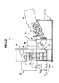
- FIG. 2 is a front cross-sectional view of a bobbin supplying device
- FIG. 3 is a perspective view of the bobbin supplying device
- FIG. 4 is a perspective view of collection boxes (a first collection box and a second collection box);
- FIG. 5A is a plan view of the first collection box
- FIG. 5B is a side view of the first collection box
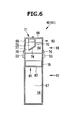
- FIG. 6 is a cross-sectional view taken along a line 6-6 shown in FIG. 5B ;
- FIG. 7A is a cross-sectional view showing a state in which a yarn-unwound bobbin is collected in the first collection box;
- FIG. 7B is a plan view showing a state in which yarn-unwound bobbins are collected in the first collection box
- FIG. 8A is a cross-sectional view showing a state in which yarn-unwound bobbins are collected in the first collection box;
- FIG. 8B is a plan view showing a state in which yarn-unwound bobbins are collected in the first collection box
- FIG. 9A is a cross-sectional view showing a state in which yarn-unwound bobbins are collected in the second collection box;
- FIG. 9B is a plan view showing a state in which yarn-unwound bobbins are collected in the second collection box.
- FIG. 10 is a side view showing a cover of the first collection box in an open state.
- the automatic winder 100 is, for example, a bobbin-tray type automatic winder.
- the automatic winder 100 mainly includes plural winding units 10, a bobbin transporting device 11, a bobbin supplying device 12, a bobbin removing device 13, and a collection box 40.
- Yarn-wound bobbins YB around which a spun yarn by a spinning machine (not shown) has been wound are loaded in bulk into a container 8 and transported to the bobbin supplying device 12, and then introduced into the bobbin supplying device 12.
- the bobbin supplying device 12 isolates each from the pile of yarn-wound bobbins YB, and then mounts one yarn-wound bobbin YB onto a tray 22 of the bobbin transporting device 11.
- the bobbin transporting device 11 transports the yarn-wound bobbins YB to each of the winding units 10.
- Each winding unit 10 unwinds the yarn from the yarn-wound bobbin YB mounted onto the tray 22 to form a package.
- An yarn-unwound bobbin B from which the yarn has been completely unwound by the winding unit 10 is discharged from the winding unit 10 by being transported on the trays 22 of the bobbin transporting device 11.
- the bobbin removing device 13 picks up the yarn-unwound bobbins B from the trays 22 of the bobbin transporting device 11 to collect the picked-up yarn-unwound bobbins B.
- a new yarn-wound bobbin YB is loaded onto the now free tray 22 by the bobbin supplying device 12 on a downstream side.
- Bobbins that have very short residual yarn wound thereon are also discharged from the winding units 10 and collected by the bobbin removing device 13.
- the yarn-unwound bobbins B include not only completely yarn-unwound bobbins but also those short residual-yarn-wound bobbins.
- Each of the winding units 10 arranged side by side unwinds the yarn that has been wound on the yarn-wound bobbin YB mounted onto the tray 22, and winds the yarn back on a winding bobbin to form a package.
- the bobbin transporting device 11 automatically supplies the yarn-wound bobbin YB to each of the winding units 10 and collects the yarn-unwound bobbin B from each of the winding units 10.
- the bobbin transporting device 11 includes a bobbin transport path 21 and a plurality of the trays 22.
- the trays 22 are transported over the bobbin transport path 21 by a conveyor, or such like.
- the yarn-wound bobbin YB or the yarn-unwound bobbin B is mounted onto each of the numerous trays 22 transported over the bobbin transport path 21.
- the bobbin supplying device 12 supplies the yarn-wound bobbin YB to, from among the trays 22 being transported, a tray 22 with no yarn-wound bobbin YB thereon.
- the bobbin supplying device 12 includes a bobbin introduction section 23, an isolating section 24, a tray placement section 25, and a bobbin moving section 26.
- the bobbin introduction section 23 is a section where the pile of yarn-wound bobbins YB transported in the container 8 is introduced.
- the isolating section 24 isolates the yarn-wound bobbins YB from the pile introduced into the bobbin introduction section 23 while elevating them.
- the isolating section 24 includes an endless belt 27, and a plurality of bobbin bearing members 28.
- the endless belt 27 is arranged in a vertical direction and forms a conveyor.
- the bobbin bearing members 28 are attached to the endless belt 27.
- the bobbin bearing member 28 has a surface to load the yarn-wound bobbin YB thereon. Only one yarn-wound bobbin YB can be loaded on this surface. Once transported to the bottom of the isolating section 24, the yarn-wound bobbins YB are loaded one on each bobbin bearing member 28 by the circular driving of the endless belt 27, and transported upward. In this manner, the yarn-wound bobbins YB are picked up one by one from the bobbin introduction section 23 and isolated.
- the tray placement section 25 receives the yarn-wound bobbin YB transported upward by the isolating section 24, makes a distinction of an unwinding end (small-diameter end of a tapered bobbin tube in an axial direction) of the yarn-wound bobbin YB and a supporting end (large-diameter end of the tapered bobbin tube in the axial direction), rotates the yarn-wound bobbin YB so that the supporting end (large-diameter end of the taper-shaped bobbin tube in the axial direction) faces downward, and mounts the yarn-wound bobbin YB onto the tray 22 of the bobbin transporting device 11.
- a tray 22 is waiting below the tray placement section 25 to receive the yarn-wound bobbin YB.
- Such tray placement sections are known in the art; for example, one is disclosed in Japanese Patent Application Laid-open No. H8-169525 .
- the bobbin moving section 26 is arranged between the bobbin introduction section 23 and the isolating section 24.
- the bobbin moving section 26 moves the pile of yarn-wound bobbins YB from the bobbin introduction section 23 to the isolating section 24.
- the bobbin moving section 26 includes a swinging and transporting section 29.
- the swinging and transporting section 29 swings to transport to the isolating section 24 a predetermined quantity of yarn-wound bobbins YB from among the pile of yarn-wound bobbins YB introduced into the bobbin introduction section 23.
- the swinging and transporting section 29 is driven to swing between a position at which it tilts towards the isolating section 24 (the state shown in FIG. 2 ) or a position at which it tilts in the opposite direction, that is, towards the bobbin introduction section 23.
- the swinging and transporting section 29 holds the yarn-wound bobbins YB in the bobbin introduction section 23 back from rushing toward the isolating section 24.
- the swinging and transporting section 29 first swings to the position at which it is tilted towards the bobbin introduction section 23. Consequently, the yarn-wound bobbins YB that have been held back are loaded on the top surface of the swinging and transporting section 29. Thereafter, the swinging and transporting section 29 is caused to swing again and tilt towards the isolating section 24.
- the swinging and transporting section 29 swings with a certain quantity of the yarn-wound bobbins YB mounted thereon, only the yarn-wound bobbins YB loaded on the swinging and transporting section 29 are introduced into the isolating section 24. Consequently, by the swinging of the swinging and transporting section 29, only a predetermined quantity of the yarn-wound bobbins YB can be transported from among the pile of yarn-wound bobbins YB in the bobbin introduction section 23 to the isolating section 24.
- the bobbin removing device 13 removes the yarn-unwound bobbins B from the trays 22 on which the yarn-unwound bobbins B discharged from the winding unit 10 are loaded from among the trays 22 that are transported by the bobbin transporting device 11.
- the bobbin removing device 13 includes a frame 31, a belt member 32, a removing lever 33, a residual-yarn-wound bobbin chute 35, a yarn-unwound-bobbin chute 36, and a residual yarn detection sensor (not shown). Bobbins with a very small amount of yarn left thereon (residual-yarn-wound bobbins) are mixed among the yarn-unwound bobbins B discharged from the winding units 10.
- the frame 31 forms the base of the bobbin removing device 13.
- the belt member 32 transports the yarn-unwound bobbins B.
- the belt member 32 is an endless belt arranged in the vertical direction.
- the removing lever 33 is an arm that is swingably attached to the frame 31.
- a picking pulley 34 is arranged on the free end of the removing lever 33.
- the removing lever 33 moves the yarn-unwound bobbin B towards the belt member 32 with the picking pulley 34 brought in contact with the yarn-unwound bobbin B mounted on the tray 22 in the bobbin transport path 21, pulls up the yarn-unwound bobbin B from the tray 22, and sends the yarn-unwound bobbin B to the belt member 32.
- the residual yarn detection sensor detects the residual-yarn-wound bobbin from among the yarn-unwound bobbins B that are transported upward along the belt member 32.
- the residual yarn detection sensor is arranged at a point along the transport path of the belt member 32.
- the residual-yarn-wound bobbin chute 35 and the yarn-unwound-bobbin chute 36 are arranged above the transport path of the belt member 32 for the yarn-unwound bobbins B.
- the residual-yarn-wound bobbin chute 35 has a tilt, which causes the yarn-unwound bobbins B with residual yarn thereon to slide and be introduced into a collection box (not shown) for yarn-unwound bobbins B with residual yarn thereon.
- the yarn-unwound bobbins B with no residual yarn are discharged through the yarn-unwound-bobbin chute 36.
- the yarn-unwound-bobbin chute 36 also has a tilt, which causes the yarn-unwound bobbins B with no residual yarn to slide and be introduced into the collection box 40.
- the bobbin removing device 13 removes the yarn-unwound bobbin B from the tray 22 with the unwinding end (top side) thereof on top. Consequently, the yarn-unwound bobbin B with no residual yarn is introduced through the yarn-unwound-bobbin chute 36 into the collection box 40 in the same orientation with its unwinding end (top side) first.
- the yarn-unwound-bobbin chute 36 extends from the bobbin removing device 13 towards the collection box 40.
- two collection boxes 40 are arranged. Consequently, the fore-end of the yarn-unwound-bobbin chute 36 is wide enough to allow the yarn-unwound bobbins B to be introduced into both the collection boxes 40.
- a separator 37 is arranged near the fore-end of the yarn-unwound-bobbin chute 36.
- the separator 37 switches guidance directions of the yarn-unwound bobbin B, thereby switching the collection box 40 to serve as an introduction destination of the yarn-unwound bobbin B between the two collection boxes 40.
- a driving source 38 (shown in Fig. 7A , 8A and 9A ) drives the separator 37 to perform this switching action.
- the collection boxes 40 are arranged side by side on a box mounting member 43 that is arranged on top of the bobbin moving section 26.
- the box mounting member 43 is a member on which the collection boxes 40 are mounted.
- the box mounting member 43 is arranged above and across the swinging and transporting section 29 of the bobbin moving section 26.
- a structure of the collection box 40 is explained in detail below with reference to FIGS. 4 to 10 .
- two collection boxes 40 are arranged side by side.
- one collection box 40 will be referred to as a first collection box 41
- the other collection box 40 will be referred to as a second collection box 42.
- the first collection box 41 and the second collection box 42 are symmetrical. The following explanation is mainly of the first collection box 41.
- the side where the yarn-unwound bobbin B is introduced through the yarn-unwound-bobbin chute 36 will be referred to, for the sake of convenience, as a yarn-unwound bobbin introduction side of the collection box 40.
- the first collection box 41 includes a box body 51, a cover 61, a receptacle 81, and a supporting unit 91.
- the box body 51 houses the yarn-unwound bobbins B.
- the box body 51 has an open top.
- the side walls of the box body 51 are substantially rectangular in shape in a horizontal cross-section.
- the box body 51 includes a removal assisting member 52 and a detecting section 53.
- a pair of opposing first side walls 54 forms the side walls of the short side of the box body 51.
- a pair of opposing second side walls 55 forms the side walls of the long side.
- the width of the first side walls 54 (length of the short side) is set shorter than the length of the yarn-unwound bobbin B.
- the width of the second side walls 55 (length of the long side) is set longer than the length of the yarn-unwound bobbin B.
- a first inner wall panel 56 is arranged parallel to the first side walls 54.
- the first inner wall panel 56 forms a housing 57 between itself and the first side wall 54 on the yarn-unwound bobbin introduction side for housing the yarn-unwound bobbins B.
- the first inner wall panel 56 is arranged on the side opposite to the yarn-unwound bobbin introduction side.
- the position of the first inner wall panel 56 is set such that the length of the long side of the housing 57 is the same as the length of the yarn-unwound bobbin B or slightly longer.
- the removal assisting member 52 facilitates the operator to put his hands in and lift up the yarn-unwound bobbins B from the first collection box 41.
- the removal assisting member 52 is provided on the second side wall 55, which is the long-side side wall of the box body 51.
- the removal assisting member 52 is a notch with an open top and a width that is shorter than the length of the yarn-unwound bobbin B. Because the removal assisting member 52 is provided on the second side wall 55, the operator can grab the pile of yarn-unwound bobbins B by inserting his hands from the side of the pile.
- the detecting section 53 detects a position of the top surface of each yarn-unwound bobbin B housed in the housing 57.
- a photoelectric sensor which includes a light emitting element and a light receiving element, is used as the detecting section 53.
- the detecting section 53 is arranged on the second side walls 55 of the box body 51.
- the light emitting element and the light receiving element of the detecting section 53 are respectively fixed outside of the box body 51, in through holes formed on opposing positions on the two second side walls 55.
- the top surfaces of the yarn-unwound bobbins B block the light emitted by the light emitting element of the detecting section 53, and blocking of the light is detected by the light receiving element of the detecting section 53.
- the detecting section 53 sends a detection signal to a controller (not shown) arranged in the automatic winder 100.
- the controller activates an alarm section, such as a lamp, to indicate to the operator that a quantity of the yarn-unwound bobbins B has reached a predetermined value.
- the controller upon receiving the detection signal from the detecting section 53, the controller operates the driving source 38 of the separator 37 to switch the guidance direction of the yarn-unwound bobbins B, thereby switching the destination collection box of the yarn-unwound bobbins B between the first collection box 41 and the second collection box 42.
- the cover 61 guides the yarn-unwound bobbins B that are introduced through the yarn-unwound-bobbin chute 36 into the housing 57 of the box body 51, and facilitates removal of the collected yarn-unwound bobbins B from the housing 57.
- the cover 61 includes a cover body 63, an opening 67, a regulating member 71, and a blocking member 75.
- the cover body 63 is supported pivotably by a shaft 76 relative to the box body 51.
- the cover body 63 can open and close relative to the box body 51.
- the shaft 76 is arranged on the side opposite to the yarn-unwound bobbin introduction side.
- the cover body 63 includes a first lateral regulating panel 64, second lateral regulating panels 65, and a top panel 66.
- the first lateral regulating panel 64 is the side wall on the short side of the cover body 63.
- the first lateral regulating panel 64 is provided only on the side opposite to the yarn-unwound bobbin introduction side (that is, on the shaft 76 side).
- the width of the first lateral regulating panel 64 is substantially the same as the width of the first side wall 54 of the box body 51.
- the second lateral regulating panels 65 prevent the yarn-unwound bobbins B being introduced from bouncing off.
- the second lateral regulating panels 65 are the side walls on the long side of the cover body 63, and the width thereof (length of the long side) is set shorter than the width of the second side wall 55 (length of the long side) of the box body 51. This is so set in the present embodiment to prevent an interference between the yarn-unwound bobbins B being introduced and the second lateral regulating panel 65 when the yarn-unwound bobbins B are introduced into the first collection box 41 through the yarn-unwound-bobbin chute 36 in a slightly oblique direction with respect to the first collection box 41 (refer to FIG. 7B ).
- the top panel 66 is the upper portion of the cover body 63.
- the top panel 66 extends across the upper portions of the first lateral regulating panel 64 and the second lateral regulating panels 65.
- the opening 67 is formed above the housing 57, through which the yarn-unwound bobbins B are introduced.
- the opening 67 is provided on the yarn-unwound bobbin introduction side to facilitate the introduction of the yarn-unwound bobbins B through the yarn-unwound-bobbin chute 36.
- the opening 67 is defined by the first side walls 54 of the box body 51 and the second lateral regulating panels 65 and the top panel 66 of the cover body 63.
- the regulating member 71 is arranged between the opening 67 and the housing 57.
- the regulating member 71 guides the yarn-unwound bobbins B being introduced into the opening 67 into the housing 57 while maintaining a uniform bobbin tube large/small-end orientation thereof.
- the regulating member 71 is fixed to the inside of the cover body 63 by a bolt.
- the regulating member 71 includes a first internal regulating panel 72, a second internal regulating panel 73, and a slanting panel 74.
- the first internal regulating panel 72 guides the yarn-unwound bobbins B being introduced into the opening 67 to one of the openings 67 while maintaining a uniform bobbin tube large/small-end orientation thereof.
- the first internal regulating panel 72 juts into the opening 67 so as to be able to definitively guide the yarn-unwound bobbins B being introduced through the yarn-unwound-bobbin chute 36.
- the second internal regulating panel 73 is arranged on an edge of the first internal regulating panel 72 that is on the side opposite to the yarn-unwound bobbin introduction side.
- the slanting panel 74 guides the yarn-unwound bobbins B being introduced into the opening 67 into the housing 57 while maintaining a uniform bobbin tube large/small-end orientation thereof.
- the slanting panel 74 is arranged contiguously with the first internal regulating panel 72, with the slant oriented to facilitate the yarn-unwound bobbins B to roll toward the second lateral regulating panel 65 of the cover body 63.
- the slanting panel 74 is arranged such that a slit-shaped (rectangular) opening is formed between the free edge of the slanting panel 74 and the second lateral regulating panel 65 of the cover body 63.
- This slit-shaped (rectangular) opening functions as a passage opening 77. That is, the slanting panel 74 forms the passage opening 77 and also guides the introduced yarn-unwound bobbins B into the passage opening 77.
- the width W of the short side is shorter than the length of the yarn-unwound bobbin B, and the length L of the long side is longer than the length of the yarn-unwound bobbin B.
- the yarn-unwound bobbins B that pass through the passage opening 77 are guided into and housed in the housing 57 with uniform bobbin tube large/small-end orientation.
- the long side of the passage opening 77 is oriented along the long side of the first collection box 41.
- the long side of the first collection box 41 is substantially oriented along an introduction direction (bobbin tube large/small-end orientation) of the yarn-unwound bobbin B. That is, the first collection box 41 is oriented so that the long side of the passage opening 77 is oriented substantially along the introduction direction of the yarn-unwound bobbin B. Consequently, the yarn-unwound bobbin B being introduced with the top side first is guided to the passage opening 77 by the regulating member 71 without changing the bobbin tube large/small-end orientation.
- the yarn-unwound bobbins B that pass through the passage opening 77 are guided into and housed in the housing 57 while maintaining the bobbin tube large/small-end orientation from the time of introduction.
- the blocking member 75 covers the removal assisting member 52 when the cover 61 is closed over the box body 51.
- the blocking member 75 extends from a lower edge of the second lateral regulating panel 65.
- the shapes of the removal assisting member 52 and the blocking member 75 are designed so that they do not butt into each other when the cover 61 is opened or closed relative to the box body 51 (refer to FIG. 10 ).
- the receptacle 81 is arranged inside the housing 57 so as to be movable upward and downward.
- the collected yarn-unwound bobbins B are loaded in the receptacle 81.
- the receptacle 81 includes a receptacle body 82, arm members 83, and a base 84.
- the receptacle body 82 is a member in which the collected yarn-unwound bobbins B are loaded.
- the receptacle body 82 is tilted, with the yarn-unwound bobbin introduction side being lower and the opposite side being higher. This arrangement is made so that the top surface of the taper-shaped yarn-unwound bobbins B is substantially horizontal when yarn-unwound bobbins B fill the housing 57 to capacity.
- the bottom-end of the taper-shaped yarn-unwound bobbins B which have been introduced with the top-end thereof first, would be at a higher level as the top of the bobbins that are collected in the receptacle body 82.
- the two arm members 83 are attached to the receptacle body 82.
- the two arm members 83 are attached on the yarn-unwound bobbin introduction side of the receptacle body 82 at the two ends of the short side.
- Two parallel slits 85 are formed in a first side wall 54 of the box body 51 and a later-explained frame 92 of the supporting unit 91.
- the two arm members 83 of the receptacle 81 penetrate through these respective slits 85.
- the base 84 is attached to the two arm members 83. With this structure, the receptacle 81 can be moved upward and downward inside the housing 57.
- the supporting unit 91 is a mechanism that lowers the receptacle 81 when the quantity of the yarn-unwound bobbins B loaded in the receptacle 81 increases, and raises the receptacle 81 when the quantity of the yarn-unwound bobbins B loaded in the receptacle 81 decreases.
- the receptacle 81 is supported by the supporting unit 91 in the above-explained manner because, if the receptacle 81 is fixed to the bottom of the collection box 40, a dropping height of the yarn-unwound bobbins B from the opening 67 to the bottom of the collection box 40 increases when the collection box 40 has only a small quantity of yarn-unwound bobbins B collected therein. If the dropping height is large, the yarn-unwound bobbins B may disadvantageously rotate and change their bobbin tube large/small-end orientation.
- the receptacle 81 is supported by the supporting unit 91 to be moved to a position nearer to the upper portion of the housing 57 when the quantity of the yarn-unwound bobbins B collected is small and to a position nearer to the lower part of the housing 57 as the quantity of the yarn-unwound bobbins B collected therein increases.
- the supporting unit 91 includes the frame 92, a guiding member 93, and an urging member 94.
- the frame 92 serves as the main body of the supporting unit 91 and is attached to the box body 51.
- the frame 92 is common to both the first collection box 41 and the second collection box 42.
- the two parallel slits 85 are formed in the first side wall 54 of the box body 51 and the frame 92.
- the guiding member 93 holds the position of the receptacle 81 when it is moved upward and downward.
- the guiding member 93 includes a sliding member 95 and a guide shaft 96.
- the sliding member 95 is fixed to the base 84 of the receptacle 81.
- the sliding member 95 has a through hole in a vertical direction; the base 84 similarly has a through hole.
- the guide shaft 96 is inserted into the through holes of both the sliding member 95 and the base 84 so that the sliding member 95 and the base 84 can slide along the guide shaft 96.
- the upper and lower ends of the guide shaft 96 are fixed to the frame 92. With this structure, the receptacle 81 is capable of moving upward and downward along the guide shaft 96.
- the urging member 94 urges the receptacle 81 upward.
- a spring is used as the urging member 94.
- the spring constant of the spring that functions as the urging member 94 is set so that the receptacle 81 is lowered when the quantity of the yarn-unwound bobbins B collected therein increases and raised when the quantity of the yarn-unwound bobbins B collected therein decreases.
- the spring constant is set so that, when the quantity of the yarn-unwound bobbins B being introduced increases, the top surfaces of the yarn-unwound bobbins B loaded in the receptacle 81 stay at a substantially even height.
- the top surfaces of the yarn-unwound bobbins B loaded in the receptacle 81 are maintained at a substantially even height that is slightly below the later-explained detecting section 53. Furthermore, when the operator removes the yarn-unwound bobbins B from the first collection box 41, the top surfaces of the yarn-unwound bobbins B loaded in the receptacle 81 are raised for a height that is equivalent to the quantity of the yarn-unwound bobbins B that have been removed, to facilitate the operator in removing the next lot of the yarn-unwound bobbins B.
- FIGS. 7A and 7B are drawings showing a state when the introduction of the yarn-unwound bobbins B into the first collection box 41 has just begun. As shown in FIG. 7B , the separator 37 of the yarn-unwound-bobbin chute 36 is switched to a position such that the yarn-unwound bobbins B are guided towards the first collection box 41.
- FIGS. 8A and 8B are drawings showing a state where the quantity of the yarn-unwound bobbins B introduced into and collected in the housing 57 has increased.
- the receptacle 81 is lowered to maintain the top surfaces of the yarn-unwound bobbins B at an even height.
- the top surfaces of the yarn-unwound bobbins B are maintained at a substantially even height that is slightly below the detecting section 53.
- FIGS. 9A and 9B are drawings showing a state when the yarn-unwound bobbins B have been collected in the housing 57 to capacity.
- the top surfaces of the yarn-unwound bobbins B block the light emitted by the light emitting element of the detecting section 53.
- the light receiving element detects the absence of the light, and sends the detection signal to the controller (not shown) arranged in the automatic winder 100.
- the controller Upon receiving the detection signal from the detecting section 53, the controller activates the alarm section, such as a lamp, to indicate to the operator that the quantity of the collected yarn-unwound bobbins B has reached a predetermined value.
- the controller upon receiving the detection signal from the detecting section 53, the controller operates the driving source 38 of the separator 37 to switch the guidance direction of the yarn-unwound bobbins B, and thereby switch the introduction destination of the yarn-unwound bobbins B from the first collection box 41 to the second collection box 42 (refer to FIG. 9B ).
- FIG. 10 is a drawing showing the cover 61 in an open state so that the operator can remove the yarn-unwound bobbins B from the first collection box 41.
- the removal assisting member 52 heretofore hidden by the blocking member 75 is exposed.
- the operator can put his hands in through the removal assisting member 52 and lift up the yarn-unwound bobbins B.
- the receptacle 81 is raised for a height equivalent to the quantity of the yarn-unwound bobbins B removed, and thereby the upper surfaces of the yarn-unwound bobbins B loaded in the receptacle 81 are raised.
- the above-explained automatic winder 100 according to the present embodiment has the following advantages.
- the bobbin supplying device 12 includes the box mounting member 43 for mounting the collection boxes 40. Therefore, there is no need to procure space for mounting the collection boxes 40 separately from where the bobbin supplying device 12 is located. Consequently, a compact automatic winder 100 can be realized leading to space-saving. Furthermore, the tasks of supplying the yarn-wound bobbins YB from the pile to the bobbin supplying device 12 and removing the yarn-unwound bobbins B from the collection boxes 40 is performed at locations that are not far apart from each other. Consequently, the distance, which the operator has to move to perform these tasks is shortened.
- the box mounting member 43 is arranged stacked above a portion of the bobbin supplying device 12. Therefore, space is efficiently utilized in a height direction (vertical direction), and space is saved in a width direction (horizontal direction) of the automatic winder 100.
- the box mounting member 43 is arranged on top of the bobbin moving section 26 that seldom needs to be reached from above. Consequently, space is efficiently utilized in the height direction (vertical direction), and space is saved in the width direction (horizontal direction) of the automatic winder 100.
- the box mounting member 43 is arranged above the swinging and transporting section 29 of the bobbin moving section 26.
- the swinging and transporting section 29 transports the yarn-wound bobbin YB by swinging and therefore causes no major vibrations or jolts. Consequently, even if the collection box 40 is arranged on the bobbin moving section 26, the collection box 40 is unaffected by the bobbin moving section 26. Furthermore, the swinging and transporting section 29 transports only a predetermined quantity of the yarn-wound bobbins YB. Consequently, the yarn-wound bobbins YB do not spill over and adversely affect the box mounting member 43 and the collection boxes 40.
- the isolating section 24 isolates each bobbin from the pile of the yarn-wound bobbins YB while elevating them. Thus, space is saved in the bobbin supplying device 12 in the horizontal direction, and thereby, overall space-saving can be achieved.
- the bobbin removing device 13 adopts a mechanism by which the yarn-unwound bobbins B are pulled upward, caused to slide down the tilted yarn-unwound-bobbin chute 36, and introduced into the collection box 40 with uniform bobbin tube large/small-end orientation.
- the collection box 40 is arranged between the opening 67 and the housing 57, and includes the regulating member 71 that maintains a uniform bobbin tube large/small-end orientation of the yarn-unwound bobbins B being introduced into the opening 67 and guides the yarn-unwound bobbins B into the housing 57. Consequently, the uniform bobbin tube large/small-end orientation at the time of introduction of the yarn-unwound bobbins B is not disturbed. Therefore, the task of aligning the yarn-unwound bobbins B in the bobbin tube large/small-end orientation, which is required in the conventional technologies before returning the yarn-unwound bobbins B to the spinning machine, is no longer necessary
- the regulating member 71 maintains a uniform bobbin tube large/small-end orientation of the yarn-unwound bobbins B by passing the yarn-unwound bobbins B through the passage opening 77 that has a short side that is shorter than the length of the yarn-unwound bobbin B and a long side that is longer than the length of the yarn-unwound bobbin B. Consequently, the yarn-unwound bobbins B being introduced into the opening 67 are guided into the housing 57 while reliably maintaining a uniform bobbin tube large/small-end orientation thereof.
- the collection box 40 is oriented so that the long side of the passage opening 77 is oriented along the introduction direction of the yarn-unwound bobbins B. Consequently, the yarn-unwound bobbins B being introduced with uniform bobbin tube large/small-end orientation easily pass through the passage opening 77 without changing their orientation, and are swiftly housed in the collection box 40.
- the cover 61 includes the opening 67 and the regulating member 71.
- the regulating member 71 forms the passage opening 77 between itself and the inner wall of the cover 61, and includes the slanting panel 74 that guides the introduced yarn-unwound bobbins B into the passage opening 77. Consequently, by opening the cover 61, the regulating member 71 can also be moved, thereby making it easy for the operator to remove the yarn-unwound bobbins B housed in the housing 57 of the box body 51.
- the housing 57 has the removal assisting member 52, which is a notch with an open top and a width that is shorter than the length of the yarn-unwound bobbin B. This allows the operator, when removing the yarn-unwound bobbins B from the collection box 40, to access the yarn-unwound bobbins B from the side of the housing 57 by inserting his hands in through the removal assisting member 52 and lifting up the yarn-unwound bobbins B. The yarn-unwound bobbins B can be removed more efficiently in this manner than when removing them from above the housing 57. With the cover 61, which includes the blocking member 75 that covers the removal assisting member 52, the yarn-unwound bobbins B are prevented from falling out through the removal assisting member 52 when the cover 61 is closed.
- the receptacle 81 in which the collected yarn-unwound bobbins B are loaded is lowered when the quantity of the yarn-unwound bobbins B collected therein increases, and raised when the quantity of the yarn-unwound bobbins B collected therein decreases. Consequently, even if the quantity of the yarn-unwound bobbins B collected is small, the dropping height of the yarn-unwound bobbins B being introduced through the opening 67 can be reduced, thereby preventing the yarn-unwound bobbins B from rotating inside the collection box 40 leading to a change in the bobbin tube large/small-end orientation.
- the operator can still easily remove the yarn-unwound bobbins B because the receptacle 81 is raised as the quantity of the yarn-unwound bobbins B in the receptacle 81 decreases.
- the collection box 40 includes the detecting section 53 that detects whether a predetermined quantity of the yarn-unwound bobbins B has been collected.
- the alarm section functions upon receiving the detection signal from the detecting section 53. Consequently, the operator comes to know that a predetermined quantity of the yarn-unwound bobbins B has been collected in the collection box 40, and therefore can remove the yarn-unwound bobbins B from the collection box 40 at an appropriate time.
- the separator 37 of the yarn-unwound-bobbin chute 36 switches the introduction destination of the yarn-unwound bobbins B among a plurality of the collection boxes 40 arranged side by side. Consequently, the yarn-unwound bobbins B are collected in a plurality of the collection boxes 40. Moreover, the yarn-unwound bobbins B can be removed from the collection box 40 in which a predetermined quantity of the yarn-unwound bobbins B has been collected even while the yarn-unwound bobbins B are being collected in another collection box 40. Consequently, the collection of the yarn-unwound bobbins B can be carried out without interruption.
- a spring is used as the urging member 94 in the supporting unit 91.
- an actuator such as an air cylinder, can be used.
- the actuator can be driven based on, for example, the detection signal of the detecting section 53, to lower the receptacle 81 as the quantity of the yarn-unwound bobbins B increases, and raise the receptacle 81 as the quantity of the yarn-unwound bobbins B decreases.
- the position of the receptacle 81 can be more accurately controlled with the actuator than with the spring.
- An automatic winder includes a bobbin transporting device, a bobbin supplying device, a winding unit, a bobbin removing device, and a collection box.
- the bobbin transporting device transports a plurality of trays.
- the bobbin supplying device supplies yarn-wound bobbins to empty trays that are being transported by the bobbin transporting device so that the bobbin transporting device transports yarn-wound bobbin mounted trays to the winding unit.
- the winding unit unwinds yarns from the yarn-wound bobbins mounted on the yarn-wound bobbin mounted trays being transported by the bobbin transporting device to form a package.
- the bobbin removing device removes yarn-unwound bobbins, which have become empty due to unwinding of yarn by the winding unit, from the trays that are being transported by the bobbin transporting device.
- the bobbin supplying device includes a box mounting member on which the collection box is mounted.
- the box mounting member is arranged on a portion of the bobbin supplying device.
- the box mounting member is arranged above a portion of the bobbin supplying device.
- the bobbin supplying device includes a bobbin introduction section, an isolating section, and a bobbin moving section.
- a bobbin introduction section Into the bobbin introduction section, a plurality of yarn-wound bobbins is introduced.
- the isolating section isolates the yarn-wound bobbins.
- the bobbin moving section moves a pile of the yarn-wound bobbins from the bobbin introduction section to the bobbin isolating section.
- the box mounting member is arranged on top of the bobbin moving section.
- the bobbin moving section includes a swinging and transporting section.
- the swinging and transporting section swings to transport to the isolating section, a predetermined quantity of the yarn-wound bobbins from among the pile of yarn-wound bobbins introduced into the bobbin introduction section.
- the box mounting member is arranged above the swinging and transporting section.
- the isolating section isolates the pile of yarn-wound bobbins while elevating the pile of yarn-wound bobbins.
- the bobbin removing device removes the yarn-unwound bobbins upwardly, and introduces the yarn-unwound bobbins into the collection box with uniform bobbin tube large/small-end orientation.
- the collection box includes a box body, an opening, and a regulating member.
- the box body has a housing, an opening, and a regulating member.
- the housing houses the yarn-unwound bobbins being introduced.
- the opening is arranged above the housing.
- the regulating member is arranged between the opening and the housing and guides the yarn-unwound bobbins being introduced into the opening into the housing while maintaining the uniform bobbin tube large/small-end orientation thereof.
- the regulating member maintains the uniform bobbin tube large/small-end orientation of the yarn-unwound bobbins by causing the yarn-unwound bobbins to pass through a rectangular passage opening with a short side thereof shorter than a length of the yarn-unwound bobbin and a long side thereof longer than the length of the yarn-unwound bobbin.
- the collection box is oriented so that the long side of the passage opening is oriented along an introduction direction of the yarn-unwound bobbins being introduced.
- the automatic winder further includes a cover that is openable and closable relative to the box body.
- the cover includes the opening and the regulating member.
- the regulating member forms the passage opening between itself and an inner wall of the cover, and further includes a slanting panel that guides the introduced yarn-unwound bobbins into the passage opening.
- the housing has a removal assisting member.
- the removal assisting member is arranged on a side wall along the long side of the passage opening.
- the removal assisting member is a notch with an open top and a width that is shorter than the length of the yarn-unwound bobbin.
- the cover has a blocking member that covers the removal assisting member.
- the automatic winder further includes a receptacle and a supporting unit.
- the receptacle is movable upward and downward inside the housing, and the collected yarn-unwound bobbins are loaded in the receptacle.
- the supporting unit lowers the receptacle when the quantity of the yarn-unwound bobbins loaded in the receptacle increases, and raises the receptacle when the quantity of the yarn-unwound bobbins loaded in the receptacle decreases.
- the collection box includes a detecting section.
- the detecting section detects whether the quantity of the yarn-unwound bobbins collected in the collection box has reached a predetermined value.
- the collection box includes an alarm section that operates upon receiving a detection signal from the detecting section.
- the automatic winder further includes a plurality of the collection boxes, a detecting section, a yarn-unwound-bobbin chute and a separator.
- the collection boxes are arranged side by side.
- the detecting section is arranged in each of the collection boxes and detects whether the quantity of the yarn-unwound bobbins collected in the respective collection box has reached a predetermined value.
- the yarn-unwound-bobbin chute is arranged in the bobbin removing device.
- the separator is arranged in the yarn-unwound-bobbin chute and switches guidance directions of the yarn-unwound bobbins, and thereby switches introduction destinations of the yarn-unwound bobbins among the plurality of the collection boxes.
- the separator switches the introduction destinations of the yarn-unwound bobbins among the plurality of the collection boxes upon receiving a detection signal from the detecting section.
- the bobbin supplying device includes the box mounting member for mounting the collection box. Therefore, there is no need to procure space for mounting the collection box at a location away from where the bobbin supplying device is located. Consequently, a compact automatic winder can be realized, achieving space-saving. Furthermore, the tasks of supplying the yarn-wound bobbins from the pile to the bobbin supplying device and removing the yarn-unwound bobbins from the collection box need not be performed at locations that are apart from each other. Consequently, the distance for which the operator has to move to perform these tasks is shortened.
- the box mounting member is arranged on a portion of the bobbin supplying device. Accordingly, space can be efficiently used in a height direction (vertical direction), and space is saved in a width direction (horizontal direction) of the automatic winder.
- the box mounting member is arranged above a portion of the bobbin supplying device. Accordingly, space can be efficiently used in the height direction (vertical direction), and space is saved in the width direction (horizontal direction) of the automatic winder.
- the box mounting member is arranged on top of the bobbin moving section that seldom needs to be reached from above. Consequently, space can be efficiently used in the height direction (vertical direction), and space is saved in the width direction (horizontal direction) of the automatic winder.
- the box mounting member is arranged above the swinging and transporting section of the bobbin moving section.
- the swinging and transporting section transports the yarn-wound bobbins by swinging and therefore causes no major vibrations or jolts. Consequently, even if the collection box is arranged on the bobbin moving section, the collection box is unaffected by the bobbin moving section. Furthermore, the swinging and transporting section transports only a predetermined quantity of the yarn-wound bobbins. Consequently, the yarn-wound bobbins do not spill over and adversely affect the box mounting member and the collection box.
- the isolating section isolates the yarn-wound bobbins while elevating them. Accordingly, space can be saved in the bobbin supplying device in the horizontal direction, and thereby, overall space-saving can be achieved.
- the bobbin removing device adopts a mechanism by which the yarn-unwound bobbins are pulled upward and introduced into the collection box with uniform bobbin tube large/small-end orientation.
- the collection box be arranged between the opening and the housing, and includes the regulating member that maintains the uniform bobbin tube large/small-end orientation of the yarn-unwound bobbins being introduced into the opening, and guides the yarn-unwound bobbins into the housing. Consequently, the uniform bobbin tube large/small-end orientation at the time of introduction of the yarn-unwound bobbins into the opening is not disturbed when the yarn-unwound bobbins are guided into the housing. Therefore, there is no need to perform the operation of aligning the bobbin tube large/small-end orientation before returning the yarn-unwound bobbins to the spinning machine.
- the regulating member maintains the uniform bobbin tube large/small-end orientation of the yarn-unwound bobbins by causing the yarn-unwound bobbins to pass through the passage opening that has a short side that is shorter than the length of the yarn-unwound bobbin and a long side that is longer than the length of the bobbin. Consequently, the yarn-unwound bobbins being introduced into the opening are guided into the housing while reliably maintaining the uniform bobbin tube large/small-end orientation thereof.
- the collection box is oriented so that the long side of the passage opening is oriented along the introduction direction of the yarn-unwound bobbins. Consequently, the yarn-unwound bobbins being introduced with uniform bobbin tube large/small-end orientation easily pass through the passage opening without changing their large/small-end orientation, and are swiftly housed in the collection box.
- the cover includes the opening and the regulating member.
- the regulating member forms the passage opening between itself and the inner wall of the cover, and includes the slanting panel that guides the introduced yarn-unwound bobbins into the passage opening. Consequently, by opening the cover, the regulating member can also be moved, thereby making it easy for the operator to remove the yarn-unwound bobbins housed in the housing of the box body.
- the housing is provided with the removal assisting member, which is a notch with an open top and a width that is shorter than the length of the yarn-unwound bobbin.
- the removal assisting member which is a notch with an open top and a width that is shorter than the length of the yarn-unwound bobbin.
- the receptacle in which the collected yarn-unwound bobbins are loaded can be lowered when the quantity of the yarn-unwound bobbins collected therein increases and raised when the quantity of the yarn-unwound bobbins collected therein decreases. Consequently, even if the quantity of the yarn-unwound bobbins collected is small, the dropping height of the yarn-unwound bobbins being introduced through the opening can be reduced, thereby preventing the yarn-unwound bobbins from disadvantageously rotating inside the collection box and changing the bobbin tube large/small-end orientation.
- the receptacle is raised as the quantity of the yarn-unwound bobbins in the receptacle decreases. This allows the operator, even if the quantity of the yarn-unwound bobbins loaded in the receptacle decreases, to still easily remove the yarn-unwound bobbins from the collection box.
- the collection box includes the detecting section that detects whether a predetermined quantity of the yarn-unwound bobbins has been collected.
- the alarm section operates upon receiving a detection signal from the detecting section. Consequently, the operator comes to know that a predetermined quantity of the yarn-unwound bobbins has been collected in the collection box, and therefore can remove the yarn-unwound bobbins from the collection box at an appropriate time.
- a plurality of the collection boxes are arranged side by side.
- the separator of the yarn-unwound-bobbin chute selects one of the collection boxes to serve as the introduction destination of the yarn-unwound bobbins. Consequently, the yarn-unwound bobbins can be collected depending on their types in separate collection boxes.
- the yarn-unwound bobbins can be removed from one collection box in which a predetermined quantity of the yarn-unwound bobbins is collected even while the yarn-unwound bobbins are being collected in another collection box. Consequently, the collection of the yarn-unwound bobbins can be carried out without interruption.
Landscapes
- Replacing, Conveying, And Pick-Finding For Filamentary Materials (AREA)
- Spinning Or Twisting Of Yarns (AREA)
Abstract
Description
- The present invention relates to an automatic winder.
- Automatic winders that have plural winding units arranged side by side are known in the art. A bobbin-tray type automatic winder typically includes plural winding units, a bobbin supplying device, a bobbin transporting device, a yarn-unwound bobbin removing device, and such like. Bobbins around which a spun yarn by a spinning machine is wound (hereinafter, "yarn-wound bobbins") are loaded into a container in bulk, transported to the bobbin supplying device, and introduced into the bobbin supplying device. The bobbin supplying device isolates each bobbin from a pile of the introduced yarn-wound bobbins, and then mounts the isolated yarn-wound bobbins onto trays of the bobbin transporting device. The bobbin transporting device transports the yarn-wound bobbins to each of the winding units. Each winding unit unwinds the yarn from the yarn-wound bobbin that is mounted onto the tray to form a package.
- The bobbins from which the yarns have been completely unwound by the winding units (hereinafter, "yarn-unwound bobbins") are discharged from the winding units by being transported on the trays of the bobbin transporting device. The yarn-unwound bobbin removing device removes the yarn-unwound bobbins from the trays of the bobbin transporting device. A fresh pile of yarn-wound bobbins are loaded by the bobbin supplying device on downstream-side ones of the trays, from which the yarn-unwound bobbins have been removed.
- Meanwhile, the yarn-unwound bobbins removed by the yarn-unwound bobbin removing device are discharged into a collection box through a yarn-unwound-bobbin chute. The collection box is arranged at a location that is different from where the bobbin supplying device is located, for example, on the floor. Because space needs to be procured at the location separately from where the bobbin supplying device is located to arrange the collection box, the automatic winder has a disadvantage from space-saving perspective.
- Furthermore, the operation of removing the yarn-unwound bobbins from the collection box that is arranged at the location different from where the bobbin supplying device is located also has to be performed away from where the bobbin supplying device is located. The acts of supplying the yarn-wound bobbins from the pile to the bobbin supplying device and removing the yarn-unwound bobbins from the collection box at different locations increases a movement distance of an operator.
- Moreover, when the yarn-unwound bobbins pass through the yarn-unwound-bobbin chute, the orientations of the taper-shaped bobbin tubes are uniform with respect to the large-diameter end and small-diameter end of the bobbin tubes in an axial direction thereof (bobbin tube large/small-end orientation). However, the yarn-unwound bobbins, after having passed through the yarn-unwound-bobbin chute, are introduced haphazardly into the collection box, leading to disarray with random bobbin tube large/small-end orientations. When returning the yarn-unwound bobbins to the spinning machine thereafter, the bobbin tube large/small-end orientations of the yarn-unwound bobbins need to be made uniform again. If the bobbin tubes large/small-end orientations of the yarn-unwound bobbins are not uniform, a bobbin aligning task needs to be performed to make the bobbin tube large/small-end orientations of the yarn-unwound bobbins uniform before returning the yarn-unwound bobbins to the spinning machine. In the conventional apparatus, this troublesome bobbin aligning task is performed manually by the operator.
- Japanese Patent Application Laid-open No.
H3-111383 bobbin box 52 that accommodates discharged yarn-unwound bobbins with uniform bobbin tube large/small-end orientation thereof. However, apart from thebobbin box 52, a receivingmember 54 is also required. Moreover, thebobbin box 52 needs to be divided into compartments by using dividingpanels 55, and therefore aconveyor 51 is required for performing pitch feeding of thebobbin box 52. Furthermore, thebobbin box 52 is arranged in a yarn-unwound bobbin processing apparatus, and no bobbin supplying device is cited. - The present invention has been made in view of the problems described above. One object of the present invention is to realize a compact automatic winder to achieve space-saving. Another object of the present invention is to shorten the distance for which the operator has to move for performing the tasks by bringing the locations where the tasks of supplying the yarn-wound bobbins from the pile to the bobbin supplying device and removing the yarn-unwound bobbins from the collection box close to each other. Still another object of the present invention is to render unnecessary the bobbin aligning task to make the bobbin tube large/small-end orientations of all the yarn-unwound bobbins uniform.
- The problems that the present invention has been made to solve have been explained above. The means to solve those problems are explained below.
- That is, an automatic winder according to an aspect of the present invention includes a bobbin transporting device, a bobbin supplying device, a winding unit, a bobbin removing device, and a collection box. The bobbin transporting device transports a plurality of trays. The winding unit unwinds yarns from the yarn-wound bobbins mounted on the trays being transported by the bobbin transporting device to form a package. The bobbin supplying device supplies yarn-wound bobbins to empty trays that are being transported by the bobbin transporting device so that the bobbin transporting device transports yarn-wound bobbin mounted trays to the winding unit. The bobbin removing device removes yarn-unwound bobbins, which have become empty due to unwinding of yarn by the winding unit, from the trays that are being transported by the bobbin transporting device. In the collection box, the yarn-unwound bobbins removed by the bobbin removing device are collected. The bobbin supplying device includes a box mounting member on which the collection box is mounted.
- The above and other objects, features, advantages and the technical and industrial significance of this invention will be better understood by reading the following detailed description of presently preferred embodiments of the invention, when considered in connection with the accompanying drawings.
-
FIG. 1 is a schematic front-view of an automatic winder according to a first embodiment of the present invention; -
FIG. 2 is a front cross-sectional view of a bobbin supplying device; -
FIG. 3 is a perspective view of the bobbin supplying device; -
FIG. 4 is a perspective view of collection boxes (a first collection box and a second collection box); -
FIG. 5A is a plan view of the first collection box; -
FIG. 5B is a side view of the first collection box; -
FIG. 6 is a cross-sectional view taken along a line 6-6 shown inFIG. 5B ; -
FIG. 7A is a cross-sectional view showing a state in which a yarn-unwound bobbin is collected in the first collection box; -
FIG. 7B is a plan view showing a state in which yarn-unwound bobbins are collected in the first collection box; -
FIG. 8A is a cross-sectional view showing a state in which yarn-unwound bobbins are collected in the first collection box; -
FIG. 8B is a plan view showing a state in which yarn-unwound bobbins are collected in the first collection box; -
FIG. 9A is a cross-sectional view showing a state in which yarn-unwound bobbins are collected in the second collection box; -
FIG. 9B is a plan view showing a state in which yarn-unwound bobbins are collected in the second collection box; and -
FIG. 10 is a side view showing a cover of the first collection box in an open state. - Exemplary embodiments of the present invention are explained in detail below with reference to the accompanying drawings.
- An
automatic winder 100 according to a first embodiment of the present invention is explained with reference toFIGS. 1 to 10 . Theautomatic winder 100 is, for example, a bobbin-tray type automatic winder. - First, an overview of the
automatic winder 100 is explained As shown inFIG. 1 , theautomatic winder 100 mainly includes plural windingunits 10, abobbin transporting device 11, abobbin supplying device 12, abobbin removing device 13, and acollection box 40. - Yarn-wound bobbins YB around which a spun yarn by a spinning machine (not shown) has been wound are loaded in bulk into a container 8 and transported to the
bobbin supplying device 12, and then introduced into thebobbin supplying device 12. Thebobbin supplying device 12 isolates each from the pile of yarn-wound bobbins YB, and then mounts one yarn-wound bobbin YB onto atray 22 of thebobbin transporting device 11. Thebobbin transporting device 11 transports the yarn-wound bobbins YB to each of the windingunits 10. Each windingunit 10 unwinds the yarn from the yarn-wound bobbin YB mounted onto thetray 22 to form a package. - An yarn-unwound bobbin B from which the yarn has been completely unwound by the winding
unit 10 is discharged from the windingunit 10 by being transported on thetrays 22 of thebobbin transporting device 11. Thebobbin removing device 13 picks up the yarn-unwound bobbins B from thetrays 22 of thebobbin transporting device 11 to collect the picked-up yarn-unwound bobbins B. A new yarn-wound bobbin YB is loaded onto the nowfree tray 22 by thebobbin supplying device 12 on a downstream side. Bobbins that have very short residual yarn wound thereon are also discharged from the windingunits 10 and collected by thebobbin removing device 13. Thus, the yarn-unwound bobbins B include not only completely yarn-unwound bobbins but also those short residual-yarn-wound bobbins. - The devices included in the
automatic winder 100 are explained in detail below with reference toFIGS. 1 to 3 . - Each of the winding
units 10 arranged side by side unwinds the yarn that has been wound on the yarn-wound bobbin YB mounted onto thetray 22, and winds the yarn back on a winding bobbin to form a package. - The
bobbin transporting device 11 automatically supplies the yarn-wound bobbin YB to each of the windingunits 10 and collects the yarn-unwound bobbin B from each of the windingunits 10. Thebobbin transporting device 11 includes abobbin transport path 21 and a plurality of thetrays 22. Thetrays 22 are transported over thebobbin transport path 21 by a conveyor, or such like. The yarn-wound bobbin YB or the yarn-unwound bobbin B is mounted onto each of thenumerous trays 22 transported over thebobbin transport path 21. - The
bobbin supplying device 12 supplies the yarn-wound bobbin YB to, from among thetrays 22 being transported, atray 22 with no yarn-wound bobbin YB thereon. Thebobbin supplying device 12 includes abobbin introduction section 23, an isolatingsection 24, atray placement section 25, and abobbin moving section 26. - The
bobbin introduction section 23 is a section where the pile of yarn-wound bobbins YB transported in the container 8 is introduced. - The isolating
section 24 isolates the yarn-wound bobbins YB from the pile introduced into thebobbin introduction section 23 while elevating them. The isolatingsection 24 includes anendless belt 27, and a plurality ofbobbin bearing members 28. Theendless belt 27 is arranged in a vertical direction and forms a conveyor. Thebobbin bearing members 28 are attached to theendless belt 27. - The
bobbin bearing member 28 has a surface to load the yarn-wound bobbin YB thereon. Only one yarn-wound bobbin YB can be loaded on this surface. Once transported to the bottom of the isolatingsection 24, the yarn-wound bobbins YB are loaded one on eachbobbin bearing member 28 by the circular driving of theendless belt 27, and transported upward. In this manner, the yarn-wound bobbins YB are picked up one by one from thebobbin introduction section 23 and isolated. - The
tray placement section 25 receives the yarn-wound bobbin YB transported upward by the isolatingsection 24, makes a distinction of an unwinding end (small-diameter end of a tapered bobbin tube in an axial direction) of the yarn-wound bobbin YB and a supporting end (large-diameter end of the tapered bobbin tube in the axial direction), rotates the yarn-wound bobbin YB so that the supporting end (large-diameter end of the taper-shaped bobbin tube in the axial direction) faces downward, and mounts the yarn-wound bobbin YB onto thetray 22 of thebobbin transporting device 11. Atray 22 is waiting below thetray placement section 25 to receive the yarn-wound bobbin YB. Such tray placement sections are known in the art; for example, one is disclosed in Japanese Patent Application Laid-open No.H8-169525 - The
bobbin moving section 26 is arranged between thebobbin introduction section 23 and the isolatingsection 24. Thebobbin moving section 26 moves the pile of yarn-wound bobbins YB from thebobbin introduction section 23 to the isolatingsection 24. Thebobbin moving section 26 includes a swinging and transportingsection 29. The swinging and transportingsection 29 swings to transport to the isolating section 24 a predetermined quantity of yarn-wound bobbins YB from among the pile of yarn-wound bobbins YB introduced into thebobbin introduction section 23. The swinging and transportingsection 29 is driven to swing between a position at which it tilts towards the isolating section 24 (the state shown inFIG. 2 ) or a position at which it tilts in the opposite direction, that is, towards thebobbin introduction section 23. - At the position of being tilted toward the isolating
section 24, the swinging and transportingsection 29 holds the yarn-wound bobbins YB in thebobbin introduction section 23 back from rushing toward the isolatingsection 24. To transport the yarn-wound bobbins YB from thebobbin introduction section 23 to the isolatingsection 24, the swinging and transportingsection 29 first swings to the position at which it is tilted towards thebobbin introduction section 23. Consequently, the yarn-wound bobbins YB that have been held back are loaded on the top surface of the swinging and transportingsection 29. Thereafter, the swinging and transportingsection 29 is caused to swing again and tilt towards the isolatingsection 24. Because the swinging and transportingsection 29 swings with a certain quantity of the yarn-wound bobbins YB mounted thereon, only the yarn-wound bobbins YB loaded on the swinging and transportingsection 29 are introduced into the isolatingsection 24. Consequently, by the swinging of the swinging and transportingsection 29, only a predetermined quantity of the yarn-wound bobbins YB can be transported from among the pile of yarn-wound bobbins YB in thebobbin introduction section 23 to the isolatingsection 24. - The
bobbin removing device 13 removes the yarn-unwound bobbins B from thetrays 22 on which the yarn-unwound bobbins B discharged from the windingunit 10 are loaded from among thetrays 22 that are transported by thebobbin transporting device 11. Thebobbin removing device 13 includes aframe 31, abelt member 32, a removinglever 33, a residual-yarn-wound bobbin chute 35, a yarn-unwound-bobbin chute 36, and a residual yarn detection sensor (not shown). Bobbins with a very small amount of yarn left thereon (residual-yarn-wound bobbins) are mixed among the yarn-unwound bobbins B discharged from the windingunits 10. - The
frame 31 forms the base of thebobbin removing device 13. Thebelt member 32 transports the yarn-unwound bobbins B. Thebelt member 32 is an endless belt arranged in the vertical direction. The removinglever 33 is an arm that is swingably attached to theframe 31. A picking pulley 34 is arranged on the free end of the removinglever 33. The removinglever 33 moves the yarn-unwound bobbin B towards thebelt member 32 with the picking pulley 34 brought in contact with the yarn-unwound bobbin B mounted on thetray 22 in thebobbin transport path 21, pulls up the yarn-unwound bobbin B from thetray 22, and sends the yarn-unwound bobbin B to thebelt member 32. - The residual yarn detection sensor (not shown) detects the residual-yarn-wound bobbin from among the yarn-unwound bobbins B that are transported upward along the
belt member 32. The residual yarn detection sensor is arranged at a point along the transport path of thebelt member 32. The residual-yarn-wound bobbin chute 35 and the yarn-unwound-bobbin chute 36 are arranged above the transport path of thebelt member 32 for the yarn-unwound bobbins B. - Those yarn-unwound bobbins B detected by the residual yarn detection sensor to have residual yarn thereon are discharged through the residual-yarn-
wound bobbin chute 35. The residual-yarn-wound bobbin chute 35 has a tilt, which causes the yarn-unwound bobbins B with residual yarn thereon to slide and be introduced into a collection box (not shown) for yarn-unwound bobbins B with residual yarn thereon. - The yarn-unwound bobbins B with no residual yarn are discharged through the yarn-unwound-
bobbin chute 36. The yarn-unwound-bobbin chute 36 also has a tilt, which causes the yarn-unwound bobbins B with no residual yarn to slide and be introduced into thecollection box 40. Thebobbin removing device 13 removes the yarn-unwound bobbin B from thetray 22 with the unwinding end (top side) thereof on top. Consequently, the yarn-unwound bobbin B with no residual yarn is introduced through the yarn-unwound-bobbin chute 36 into thecollection box 40 in the same orientation with its unwinding end (top side) first. - The yarn-unwound-
bobbin chute 36 extends from thebobbin removing device 13 towards thecollection box 40. In the present embodiment, twocollection boxes 40 are arranged. Consequently, the fore-end of the yarn-unwound-bobbin chute 36 is wide enough to allow the yarn-unwound bobbins B to be introduced into both thecollection boxes 40. - A
separator 37 is arranged near the fore-end of the yarn-unwound-bobbin chute 36. Theseparator 37 switches guidance directions of the yarn-unwound bobbin B, thereby switching thecollection box 40 to serve as an introduction destination of the yarn-unwound bobbin B between the twocollection boxes 40. A driving source 38 (shown inFig. 7A ,8A and9A ) drives theseparator 37 to perform this switching action. - In the present embodiment, the
collection boxes 40 are arranged side by side on abox mounting member 43 that is arranged on top of thebobbin moving section 26. Thebox mounting member 43 is a member on which thecollection boxes 40 are mounted. In the present embodiment, thebox mounting member 43 is arranged above and across the swinging and transportingsection 29 of thebobbin moving section 26. - A structure of the
collection box 40 is explained in detail below with reference toFIGS. 4 to 10 . As shown inFIG. 4 , in the present embodiment, twocollection boxes 40 are arranged side by side. In the following description, for the sake of convenience, onecollection box 40 will be referred to as afirst collection box 41, and theother collection box 40 will be referred to as asecond collection box 42. Thefirst collection box 41 and thesecond collection box 42 are symmetrical. The following explanation is mainly of thefirst collection box 41. - The side where the yarn-unwound bobbin B is introduced through the yarn-unwound-
bobbin chute 36 will be referred to, for the sake of convenience, as a yarn-unwound bobbin introduction side of thecollection box 40. - A structure of the
first collection box 41 is explained below. As shown inFIGS. 4 ,5A and 5B , thefirst collection box 41 includes abox body 51, acover 61, areceptacle 81, and a supportingunit 91. - The
box body 51 houses the yarn-unwound bobbins B. Thebox body 51 has an open top. The side walls of thebox body 51 are substantially rectangular in shape in a horizontal cross-section. Thebox body 51 includes aremoval assisting member 52 and a detectingsection 53. - A pair of opposing
first side walls 54 forms the side walls of the short side of thebox body 51. A pair of opposingsecond side walls 55 forms the side walls of the long side. The width of the first side walls 54 (length of the short side) is set shorter than the length of the yarn-unwound bobbin B. The width of the second side walls 55 (length of the long side) is set longer than the length of the yarn-unwound bobbin B. - Inside the
box body 51, a firstinner wall panel 56 is arranged parallel to thefirst side walls 54. The firstinner wall panel 56 forms ahousing 57 between itself and thefirst side wall 54 on the yarn-unwound bobbin introduction side for housing the yarn-unwound bobbins B. The firstinner wall panel 56 is arranged on the side opposite to the yarn-unwound bobbin introduction side. To prevent the yarn-unwound bobbin B from rotating inside thehousing 57 leading to a change in the bobbin tube large/small-end orientation, the position of the firstinner wall panel 56 is set such that the length of the long side of thehousing 57 is the same as the length of the yarn-unwound bobbin B or slightly longer. - The
removal assisting member 52 facilitates the operator to put his hands in and lift up the yarn-unwound bobbins B from thefirst collection box 41. Theremoval assisting member 52 is provided on thesecond side wall 55, which is the long-side side wall of thebox body 51. Theremoval assisting member 52 is a notch with an open top and a width that is shorter than the length of the yarn-unwound bobbin B. Because theremoval assisting member 52 is provided on thesecond side wall 55, the operator can grab the pile of yarn-unwound bobbins B by inserting his hands from the side of the pile. - The detecting
section 53 detects a position of the top surface of each yarn-unwound bobbin B housed in thehousing 57. In the present embodiment, a photoelectric sensor, which includes a light emitting element and a light receiving element, is used as the detectingsection 53. The detectingsection 53 is arranged on thesecond side walls 55 of thebox body 51. The light emitting element and the light receiving element of the detectingsection 53 are respectively fixed outside of thebox body 51, in through holes formed on opposing positions on the twosecond side walls 55. - When the yarn-unwound bobbins B are collected in and eventually fill the
housing 57 to capacity, the top surfaces of the yarn-unwound bobbins B block the light emitted by the light emitting element of the detectingsection 53, and blocking of the light is detected by the light receiving element of the detectingsection 53. The detectingsection 53 sends a detection signal to a controller (not shown) arranged in theautomatic winder 100. Upon receiving the detection signal from the detectingsection 53, the controller activates an alarm section, such as a lamp, to indicate to the operator that a quantity of the yarn-unwound bobbins B has reached a predetermined value. Also, upon receiving the detection signal from the detectingsection 53, the controller operates the drivingsource 38 of theseparator 37 to switch the guidance direction of the yarn-unwound bobbins B, thereby switching the destination collection box of the yarn-unwound bobbins B between thefirst collection box 41 and thesecond collection box 42. - The
cover 61 guides the yarn-unwound bobbins B that are introduced through the yarn-unwound-bobbin chute 36 into thehousing 57 of thebox body 51, and facilitates removal of the collected yarn-unwound bobbins B from thehousing 57. Thecover 61 includes acover body 63, anopening 67, a regulatingmember 71, and a blockingmember 75. - The
cover body 63 is supported pivotably by ashaft 76 relative to thebox body 51. Thecover body 63 can open and close relative to thebox body 51. Theshaft 76 is arranged on the side opposite to the yarn-unwound bobbin introduction side. Thecover body 63 includes a firstlateral regulating panel 64, secondlateral regulating panels 65, and atop panel 66. The firstlateral regulating panel 64 is the side wall on the short side of thecover body 63. The firstlateral regulating panel 64 is provided only on the side opposite to the yarn-unwound bobbin introduction side (that is, on theshaft 76 side). The width of the firstlateral regulating panel 64 is substantially the same as the width of thefirst side wall 54 of thebox body 51. - The second
lateral regulating panels 65 prevent the yarn-unwound bobbins B being introduced from bouncing off. The secondlateral regulating panels 65 are the side walls on the long side of thecover body 63, and the width thereof (length of the long side) is set shorter than the width of the second side wall 55 (length of the long side) of thebox body 51. This is so set in the present embodiment to prevent an interference between the yarn-unwound bobbins B being introduced and the secondlateral regulating panel 65 when the yarn-unwound bobbins B are introduced into thefirst collection box 41 through the yarn-unwound-bobbin chute 36 in a slightly oblique direction with respect to the first collection box 41 (refer toFIG. 7B ). - The
top panel 66 is the upper portion of thecover body 63. Thetop panel 66 extends across the upper portions of the firstlateral regulating panel 64 and the secondlateral regulating panels 65. - The
opening 67 is formed above thehousing 57, through which the yarn-unwound bobbins B are introduced. Theopening 67 is provided on the yarn-unwound bobbin introduction side to facilitate the introduction of the yarn-unwound bobbins B through the yarn-unwound-bobbin chute 36. Theopening 67 is defined by thefirst side walls 54 of thebox body 51 and the secondlateral regulating panels 65 and thetop panel 66 of thecover body 63. - As shown in
FIGS. 4 to 6 , the regulatingmember 71 is arranged between theopening 67 and thehousing 57. The regulatingmember 71 guides the yarn-unwound bobbins B being introduced into theopening 67 into thehousing 57 while maintaining a uniform bobbin tube large/small-end orientation thereof. The regulatingmember 71 is fixed to the inside of thecover body 63 by a bolt. The regulatingmember 71 includes a firstinternal regulating panel 72, a second internal regulatingpanel 73, and a slantingpanel 74. - The first
internal regulating panel 72 guides the yarn-unwound bobbins B being introduced into theopening 67 to one of theopenings 67 while maintaining a uniform bobbin tube large/small-end orientation thereof. The firstinternal regulating panel 72 juts into theopening 67 so as to be able to definitively guide the yarn-unwound bobbins B being introduced through the yarn-unwound-bobbin chute 36. The second internal regulatingpanel 73 is arranged on an edge of the firstinternal regulating panel 72 that is on the side opposite to the yarn-unwound bobbin introduction side. - The slanting
panel 74 guides the yarn-unwound bobbins B being introduced into theopening 67 into thehousing 57 while maintaining a uniform bobbin tube large/small-end orientation thereof. The slantingpanel 74 is arranged contiguously with the firstinternal regulating panel 72, with the slant oriented to facilitate the yarn-unwound bobbins B to roll toward the secondlateral regulating panel 65 of thecover body 63. The slantingpanel 74 is arranged such that a slit-shaped (rectangular) opening is formed between the free edge of the slantingpanel 74 and the secondlateral regulating panel 65 of thecover body 63. This slit-shaped (rectangular) opening functions as apassage opening 77. That is, the slantingpanel 74 forms thepassage opening 77 and also guides the introduced yarn-unwound bobbins B into thepassage opening 77. - As shown in
FIGS. 5A, 5B , and6 , if W is a width of a short side and L is a length of a long side of thepassage opening 77, the width W of the short side is shorter than the length of the yarn-unwound bobbin B, and the length L of the long side is longer than the length of the yarn-unwound bobbin B. The yarn-unwound bobbins B that pass through thepassage opening 77 are guided into and housed in thehousing 57 with uniform bobbin tube large/small-end orientation. By adjusting the position where the regulatingmember 71 is fixed to thecover body 63, the width W of the short side of thepassage opening 77 can be adjusted to suit the type of the yarn-unwound bobbin B. - Furthermore, in the present embodiment, the long side of the
passage opening 77 is oriented along the long side of thefirst collection box 41. The long side of thefirst collection box 41 is substantially oriented along an introduction direction (bobbin tube large/small-end orientation) of the yarn-unwound bobbin B. That is, thefirst collection box 41 is oriented so that the long side of thepassage opening 77 is oriented substantially along the introduction direction of the yarn-unwound bobbin B. Consequently, the yarn-unwound bobbin B being introduced with the top side first is guided to thepassage opening 77 by the regulatingmember 71 without changing the bobbin tube large/small-end orientation. The yarn-unwound bobbins B that pass through thepassage opening 77 are guided into and housed in thehousing 57 while maintaining the bobbin tube large/small-end orientation from the time of introduction. - The blocking
member 75 covers theremoval assisting member 52 when thecover 61 is closed over thebox body 51. The blockingmember 75 extends from a lower edge of the secondlateral regulating panel 65. To make the blockingmember 75 fit into the notch of theremoval assisting member 52 when thecover 61 is closed over thebox body 51, the shapes of theremoval assisting member 52 and the blockingmember 75 are designed so that they do not butt into each other when thecover 61 is opened or closed relative to the box body 51 (refer toFIG. 10 ). - The
receptacle 81 is arranged inside thehousing 57 so as to be movable upward and downward. The collected yarn-unwound bobbins B are loaded in thereceptacle 81. Thereceptacle 81 includes areceptacle body 82,arm members 83, and abase 84. - The
receptacle body 82 is a member in which the collected yarn-unwound bobbins B are loaded. Thereceptacle body 82 is tilted, with the yarn-unwound bobbin introduction side being lower and the opposite side being higher. This arrangement is made so that the top surface of the taper-shaped yarn-unwound bobbins B is substantially horizontal when yarn-unwound bobbins B fill thehousing 57 to capacity. Without a tilt of thereceptacle body 82, the bottom-end of the taper-shaped yarn-unwound bobbins B, which have been introduced with the top-end thereof first, would be at a higher level as the top of the bobbins that are collected in thereceptacle body 82. - The two
arm members 83 are attached to thereceptacle body 82. The twoarm members 83 are attached on the yarn-unwound bobbin introduction side of thereceptacle body 82 at the two ends of the short side. Twoparallel slits 85 are formed in afirst side wall 54 of thebox body 51 and a later-explainedframe 92 of the supportingunit 91. The twoarm members 83 of thereceptacle 81 penetrate through theserespective slits 85. On the side opposite to thereceptacle body 82, thebase 84 is attached to the twoarm members 83. With this structure, thereceptacle 81 can be moved upward and downward inside thehousing 57. - As shown in
FIGS. 4 ,5A, and 5B , the supportingunit 91 is a mechanism that lowers thereceptacle 81 when the quantity of the yarn-unwound bobbins B loaded in thereceptacle 81 increases, and raises thereceptacle 81 when the quantity of the yarn-unwound bobbins B loaded in thereceptacle 81 decreases. - The
receptacle 81 is supported by the supportingunit 91 in the above-explained manner because, if thereceptacle 81 is fixed to the bottom of thecollection box 40, a dropping height of the yarn-unwound bobbins B from theopening 67 to the bottom of thecollection box 40 increases when thecollection box 40 has only a small quantity of yarn-unwound bobbins B collected therein. If the dropping height is large, the yarn-unwound bobbins B may disadvantageously rotate and change their bobbin tube large/small-end orientation. Consequently, thereceptacle 81 is supported by the supportingunit 91 to be moved to a position nearer to the upper portion of thehousing 57 when the quantity of the yarn-unwound bobbins B collected is small and to a position nearer to the lower part of thehousing 57 as the quantity of the yarn-unwound bobbins B collected therein increases. - A structure of the supporting
unit 91 is explained below. The supportingunit 91 includes theframe 92, a guidingmember 93, and an urgingmember 94. Theframe 92 serves as the main body of the supportingunit 91 and is attached to thebox body 51. Theframe 92 is common to both thefirst collection box 41 and thesecond collection box 42. As explained above, the twoparallel slits 85 are formed in thefirst side wall 54 of thebox body 51 and theframe 92. - The guiding
member 93 holds the position of thereceptacle 81 when it is moved upward and downward. The guidingmember 93 includes a slidingmember 95 and aguide shaft 96. The slidingmember 95 is fixed to thebase 84 of thereceptacle 81. The slidingmember 95 has a through hole in a vertical direction; the base 84 similarly has a through hole. Theguide shaft 96 is inserted into the through holes of both the slidingmember 95 and the base 84 so that the slidingmember 95 and the base 84 can slide along theguide shaft 96. The upper and lower ends of theguide shaft 96 are fixed to theframe 92. With this structure, thereceptacle 81 is capable of moving upward and downward along theguide shaft 96. - The urging
member 94 urges thereceptacle 81 upward. In the present embodiment, a spring is used as the urgingmember 94. The spring constant of the spring that functions as the urgingmember 94 is set so that thereceptacle 81 is lowered when the quantity of the yarn-unwound bobbins B collected therein increases and raised when the quantity of the yarn-unwound bobbins B collected therein decreases. Specifically, the spring constant is set so that, when the quantity of the yarn-unwound bobbins B being introduced increases, the top surfaces of the yarn-unwound bobbins B loaded in thereceptacle 81 stay at a substantially even height. In the present embodiment, the top surfaces of the yarn-unwound bobbins B loaded in thereceptacle 81 are maintained at a substantially even height that is slightly below the later-explained detectingsection 53. Furthermore, when the operator removes the yarn-unwound bobbins B from thefirst collection box 41, the top surfaces of the yarn-unwound bobbins B loaded in thereceptacle 81 are raised for a height that is equivalent to the quantity of the yarn-unwound bobbins B that have been removed, to facilitate the operator in removing the next lot of the yarn-unwound bobbins B. - The structure of the
automatic winder 100 had beenis explained so far. How the yarn-unwound bobbins B are collected in thefirst collection box 41 is now explained with reference toFIGS. 7A to 10 . -
FIGS. 7A and 7B are drawings showing a state when the introduction of the yarn-unwound bobbins B into thefirst collection box 41 has just begun. As shown inFIG. 7B , theseparator 37 of the yarn-unwound-bobbin chute 36 is switched to a position such that the yarn-unwound bobbins B are guided towards thefirst collection box 41. -
FIGS. 8A and 8B are drawings showing a state where the quantity of the yarn-unwound bobbins B introduced into and collected in thehousing 57 has increased. As the quantity of the yarn-unwound bobbins B collected in thehousing 57 increases, thereceptacle 81 is lowered to maintain the top surfaces of the yarn-unwound bobbins B at an even height. In the present embodiment, the top surfaces of the yarn-unwound bobbins B are maintained at a substantially even height that is slightly below the detectingsection 53. -
FIGS. 9A and 9B are drawings showing a state when the yarn-unwound bobbins B have been collected in thehousing 57 to capacity. In this state, the top surfaces of the yarn-unwound bobbins B block the light emitted by the light emitting element of the detectingsection 53. The light receiving element detects the absence of the light, and sends the detection signal to the controller (not shown) arranged in theautomatic winder 100. Upon receiving the detection signal from the detectingsection 53, the controller activates the alarm section, such as a lamp, to indicate to the operator that the quantity of the collected yarn-unwound bobbins B has reached a predetermined value. Moreover, upon receiving the detection signal from the detectingsection 53, the controller operates the drivingsource 38 of theseparator 37 to switch the guidance direction of the yarn-unwound bobbins B, and thereby switch the introduction destination of the yarn-unwound bobbins B from thefirst collection box 41 to the second collection box 42 (refer toFIG. 9B ). -
FIG. 10 is a drawing showing thecover 61 in an open state so that the operator can remove the yarn-unwound bobbins B from thefirst collection box 41. When thecover 61 is opened, theremoval assisting member 52 heretofore hidden by the blockingmember 75 is exposed. The operator can put his hands in through theremoval assisting member 52 and lift up the yarn-unwound bobbins B. Once the operator removes some of the yarn-unwound bobbins B, thereceptacle 81 is raised for a height equivalent to the quantity of the yarn-unwound bobbins B removed, and thereby the upper surfaces of the yarn-unwound bobbins B loaded in thereceptacle 81 are raised. - The above-explained
automatic winder 100 according to the present embodiment has the following advantages. - The
bobbin supplying device 12 includes thebox mounting member 43 for mounting thecollection boxes 40. Therefore, there is no need to procure space for mounting thecollection boxes 40 separately from where thebobbin supplying device 12 is located. Consequently, a compactautomatic winder 100 can be realized leading to space-saving. Furthermore, the tasks of supplying the yarn-wound bobbins YB from the pile to thebobbin supplying device 12 and removing the yarn-unwound bobbins B from thecollection boxes 40 is performed at locations that are not far apart from each other. Consequently, the distance, which the operator has to move to perform these tasks is shortened. - The
box mounting member 43 is arranged stacked above a portion of thebobbin supplying device 12. Therefore, space is efficiently utilized in a height direction (vertical direction), and space is saved in a width direction (horizontal direction) of theautomatic winder 100. - In the
bobbin supplying device 12, thebox mounting member 43 is arranged on top of thebobbin moving section 26 that seldom needs to be reached from above. Consequently, space is efficiently utilized in the height direction (vertical direction), and space is saved in the width direction (horizontal direction) of theautomatic winder 100. - The
box mounting member 43 is arranged above the swinging and transportingsection 29 of thebobbin moving section 26. The swinging and transportingsection 29 transports the yarn-wound bobbin YB by swinging and therefore causes no major vibrations or jolts. Consequently, even if thecollection box 40 is arranged on thebobbin moving section 26, thecollection box 40 is unaffected by thebobbin moving section 26. Furthermore, the swinging and transportingsection 29 transports only a predetermined quantity of the yarn-wound bobbins YB. Consequently, the yarn-wound bobbins YB do not spill over and adversely affect thebox mounting member 43 and thecollection boxes 40. - The isolating
section 24 isolates each bobbin from the pile of the yarn-wound bobbins YB while elevating them. Thus, space is saved in thebobbin supplying device 12 in the horizontal direction, and thereby, overall space-saving can be achieved. - The
bobbin removing device 13 adopts a mechanism by which the yarn-unwound bobbins B are pulled upward, caused to slide down the tilted yarn-unwound-bobbin chute 36, and introduced into thecollection box 40 with uniform bobbin tube large/small-end orientation. Thecollection box 40 is arranged between theopening 67 and thehousing 57, and includes the regulatingmember 71 that maintains a uniform bobbin tube large/small-end orientation of the yarn-unwound bobbins B being introduced into theopening 67 and guides the yarn-unwound bobbins B into thehousing 57. Consequently, the uniform bobbin tube large/small-end orientation at the time of introduction of the yarn-unwound bobbins B is not disturbed. Therefore, the task of aligning the yarn-unwound bobbins B in the bobbin tube large/small-end orientation, which is required in the conventional technologies before returning the yarn-unwound bobbins B to the spinning machine, is no longer necessary. - The regulating
member 71 maintains a uniform bobbin tube large/small-end orientation of the yarn-unwound bobbins B by passing the yarn-unwound bobbins B through thepassage opening 77 that has a short side that is shorter than the length of the yarn-unwound bobbin B and a long side that is longer than the length of the yarn-unwound bobbin B. Consequently, the yarn-unwound bobbins B being introduced into theopening 67 are guided into thehousing 57 while reliably maintaining a uniform bobbin tube large/small-end orientation thereof. - The
collection box 40 is oriented so that the long side of thepassage opening 77 is oriented along the introduction direction of the yarn-unwound bobbins B. Consequently, the yarn-unwound bobbins B being introduced with uniform bobbin tube large/small-end orientation easily pass through thepassage opening 77 without changing their orientation, and are swiftly housed in thecollection box 40. - The
cover 61 includes theopening 67 and the regulatingmember 71. The regulatingmember 71 forms thepassage opening 77 between itself and the inner wall of thecover 61, and includes the slantingpanel 74 that guides the introduced yarn-unwound bobbins B into thepassage opening 77. Consequently, by opening thecover 61, the regulatingmember 71 can also be moved, thereby making it easy for the operator to remove the yarn-unwound bobbins B housed in thehousing 57 of thebox body 51. - The
housing 57 has theremoval assisting member 52, which is a notch with an open top and a width that is shorter than the length of the yarn-unwound bobbin B. This allows the operator, when removing the yarn-unwound bobbins B from thecollection box 40, to access the yarn-unwound bobbins B from the side of thehousing 57 by inserting his hands in through theremoval assisting member 52 and lifting up the yarn-unwound bobbins B. The yarn-unwound bobbins B can be removed more efficiently in this manner than when removing them from above thehousing 57. With thecover 61, which includes the blockingmember 75 that covers theremoval assisting member 52, the yarn-unwound bobbins B are prevented from falling out through theremoval assisting member 52 when thecover 61 is closed. - The
receptacle 81 in which the collected yarn-unwound bobbins B are loaded is lowered when the quantity of the yarn-unwound bobbins B collected therein increases, and raised when the quantity of the yarn-unwound bobbins B collected therein decreases. Consequently, even if the quantity of the yarn-unwound bobbins B collected is small, the dropping height of the yarn-unwound bobbins B being introduced through theopening 67 can be reduced, thereby preventing the yarn-unwound bobbins B from rotating inside thecollection box 40 leading to a change in the bobbin tube large/small-end orientation. Furthermore, even if the quantity of the yarn-unwound bobbins B loaded in thereceptacle 81 decreases as the operator removes the yarn-unwound bobbins B from thecollection box 40, the operator can still easily remove the yarn-unwound bobbins B because thereceptacle 81 is raised as the quantity of the yarn-unwound bobbins B in thereceptacle 81 decreases. - The
collection box 40 includes the detectingsection 53 that detects whether a predetermined quantity of the yarn-unwound bobbins B has been collected. The alarm section functions upon receiving the detection signal from the detectingsection 53. Consequently, the operator comes to know that a predetermined quantity of the yarn-unwound bobbins B has been collected in thecollection box 40, and therefore can remove the yarn-unwound bobbins B from thecollection box 40 at an appropriate time. - Upon receiving the detection signal from the detecting
section 53 of thecollection box 40, theseparator 37 of the yarn-unwound-bobbin chute 36 switches the introduction destination of the yarn-unwound bobbins B among a plurality of thecollection boxes 40 arranged side by side. Consequently, the yarn-unwound bobbins B are collected in a plurality of thecollection boxes 40. Moreover, the yarn-unwound bobbins B can be removed from thecollection box 40 in which a predetermined quantity of the yarn-unwound bobbins B has been collected even while the yarn-unwound bobbins B are being collected in anothercollection box 40. Consequently, the collection of the yarn-unwound bobbins B can be carried out without interruption. - Although the invention has been described with respect to specific embodiments, the present invention is not limited thereto, and various modifications can be made.
- For example, a spring is used as the urging
member 94 in the supportingunit 91. Instead, an actuator, such as an air cylinder, can be used. The actuator can be driven based on, for example, the detection signal of the detectingsection 53, to lower thereceptacle 81 as the quantity of the yarn-unwound bobbins B increases, and raise thereceptacle 81 as the quantity of the yarn-unwound bobbins B decreases. The position of thereceptacle 81 can be more accurately controlled with the actuator than with the spring. - An automatic winder according to an aspect of the present invention includes a bobbin transporting device, a bobbin supplying device, a winding unit, a bobbin removing device, and a collection box. The bobbin transporting device transports a plurality of trays. The bobbin supplying device supplies yarn-wound bobbins to empty trays that are being transported by the bobbin transporting device so that the bobbin transporting device transports yarn-wound bobbin mounted trays to the winding unit. The winding unit unwinds yarns from the yarn-wound bobbins mounted on the yarn-wound bobbin mounted trays being transported by the bobbin transporting device to form a package. The bobbin removing device removes yarn-unwound bobbins, which have become empty due to unwinding of yarn by the winding unit, from the trays that are being transported by the bobbin transporting device. In the collection box, the yarn-unwound bobbins removed by the bobbin removing device are collected. The bobbin supplying device includes a box mounting member on which the collection box is mounted.
- According to another aspect of the present invention, the box mounting member is arranged on a portion of the bobbin supplying device.
- According to still another aspect of the present invention, the box mounting member is arranged above a portion of the bobbin supplying device.
- According to still another aspect of the present invention, the bobbin supplying device includes a bobbin introduction section, an isolating section, and a bobbin moving section. Into the bobbin introduction section, a plurality of yarn-wound bobbins is introduced. The isolating section isolates the yarn-wound bobbins. The bobbin moving section moves a pile of the yarn-wound bobbins from the bobbin introduction section to the bobbin isolating section. The box mounting member is arranged on top of the bobbin moving section.
- According to still another aspect of the present invention, the bobbin moving section includes a swinging and transporting section. The swinging and transporting section swings to transport to the isolating section, a predetermined quantity of the yarn-wound bobbins from among the pile of yarn-wound bobbins introduced into the bobbin introduction section. The box mounting member is arranged above the swinging and transporting section.
- According to still another aspect of the present invention, the isolating section isolates the pile of yarn-wound bobbins while elevating the pile of yarn-wound bobbins.
- According to still another aspect of the present invention, the bobbin removing device removes the yarn-unwound bobbins upwardly, and introduces the yarn-unwound bobbins into the collection box with uniform bobbin tube large/small-end orientation. The collection box includes a box body, an opening, and a regulating member. The box body has a housing, an opening, and a regulating member. The housing houses the yarn-unwound bobbins being introduced. The opening is arranged above the housing. The regulating member is arranged between the opening and the housing and guides the yarn-unwound bobbins being introduced into the opening into the housing while maintaining the uniform bobbin tube large/small-end orientation thereof.
- According to still another aspect of the present invention, the regulating member maintains the uniform bobbin tube large/small-end orientation of the yarn-unwound bobbins by causing the yarn-unwound bobbins to pass through a rectangular passage opening with a short side thereof shorter than a length of the yarn-unwound bobbin and a long side thereof longer than the length of the yarn-unwound bobbin.
- According to still another aspect of the present invention, the collection box is oriented so that the long side of the passage opening is oriented along an introduction direction of the yarn-unwound bobbins being introduced.
- According to still another aspect of the present invention, the automatic winder further includes a cover that is openable and closable relative to the box body. The cover includes the opening and the regulating member. The regulating member forms the passage opening between itself and an inner wall of the cover, and further includes a slanting panel that guides the introduced yarn-unwound bobbins into the passage opening.
- According to still another aspect of the present invention, the housing has a removal assisting member. The removal assisting member is arranged on a side wall along the long side of the passage opening. The removal assisting member is a notch with an open top and a width that is shorter than the length of the yarn-unwound bobbin. The cover has a blocking member that covers the removal assisting member.
- According to still another aspect of the present invention, the automatic winder further includes a receptacle and a supporting unit. The receptacle is movable upward and downward inside the housing, and the collected yarn-unwound bobbins are loaded in the receptacle. The supporting unit lowers the receptacle when the quantity of the yarn-unwound bobbins loaded in the receptacle increases, and raises the receptacle when the quantity of the yarn-unwound bobbins loaded in the receptacle decreases.
- According to still another aspect of the present invention, the collection box includes a detecting section. The detecting section detects whether the quantity of the yarn-unwound bobbins collected in the collection box has reached a predetermined value. The collection box includes an alarm section that operates upon receiving a detection signal from the detecting section.
- According to still another aspect of the present invention, the automatic winder further includes a plurality of the collection boxes, a detecting section, a yarn-unwound-bobbin chute and a separator. The collection boxes are arranged side by side. The detecting section is arranged in each of the collection boxes and detects whether the quantity of the yarn-unwound bobbins collected in the respective collection box has reached a predetermined value. The yarn-unwound-bobbin chute is arranged in the bobbin removing device. The separator is arranged in the yarn-unwound-bobbin chute and switches guidance directions of the yarn-unwound bobbins, and thereby switches introduction destinations of the yarn-unwound bobbins among the plurality of the collection boxes. The separator switches the introduction destinations of the yarn-unwound bobbins among the plurality of the collection boxes upon receiving a detection signal from the detecting section.
- The advantages of the present invention are given below.
- In the automatic winder according to the present invention, the bobbin supplying device includes the box mounting member for mounting the collection box. Therefore, there is no need to procure space for mounting the collection box at a location away from where the bobbin supplying device is located. Consequently, a compact automatic winder can be realized, achieving space-saving. Furthermore, the tasks of supplying the yarn-wound bobbins from the pile to the bobbin supplying device and removing the yarn-unwound bobbins from the collection box need not be performed at locations that are apart from each other. Consequently, the distance for which the operator has to move to perform these tasks is shortened.
- It is preferable that the box mounting member is arranged on a portion of the bobbin supplying device. Accordingly, space can be efficiently used in a height direction (vertical direction), and space is saved in a width direction (horizontal direction) of the automatic winder.
- It is preferable that the box mounting member is arranged above a portion of the bobbin supplying device. Accordingly, space can be efficiently used in the height direction (vertical direction), and space is saved in the width direction (horizontal direction) of the automatic winder.
- It is preferable that the box mounting member is arranged on top of the bobbin moving section that seldom needs to be reached from above. Consequently, space can be efficiently used in the height direction (vertical direction), and space is saved in the width direction (horizontal direction) of the automatic winder.
- It is preferable that the box mounting member is arranged above the swinging and transporting section of the bobbin moving section. The swinging and transporting section transports the yarn-wound bobbins by swinging and therefore causes no major vibrations or jolts. Consequently, even if the collection box is arranged on the bobbin moving section, the collection box is unaffected by the bobbin moving section. Furthermore, the swinging and transporting section transports only a predetermined quantity of the yarn-wound bobbins. Consequently, the yarn-wound bobbins do not spill over and adversely affect the box mounting member and the collection box.
- It is preferable that the isolating section isolates the yarn-wound bobbins while elevating them. Accordingly, space can be saved in the bobbin supplying device in the horizontal direction, and thereby, overall space-saving can be achieved.
- It is preferable that the bobbin removing device adopts a mechanism by which the yarn-unwound bobbins are pulled upward and introduced into the collection box with uniform bobbin tube large/small-end orientation. Furthermore, it is preferable that the collection box be arranged between the opening and the housing, and includes the regulating member that maintains the uniform bobbin tube large/small-end orientation of the yarn-unwound bobbins being introduced into the opening, and guides the yarn-unwound bobbins into the housing. Consequently, the uniform bobbin tube large/small-end orientation at the time of introduction of the yarn-unwound bobbins into the opening is not disturbed when the yarn-unwound bobbins are guided into the housing. Therefore, there is no need to perform the operation of aligning the bobbin tube large/small-end orientation before returning the yarn-unwound bobbins to the spinning machine.
- It is preferable that the regulating member maintains the uniform bobbin tube large/small-end orientation of the yarn-unwound bobbins by causing the yarn-unwound bobbins to pass through the passage opening that has a short side that is shorter than the length of the yarn-unwound bobbin and a long side that is longer than the length of the bobbin. Consequently, the yarn-unwound bobbins being introduced into the opening are guided into the housing while reliably maintaining the uniform bobbin tube large/small-end orientation thereof.
- It is preferable that the collection box is oriented so that the long side of the passage opening is oriented along the introduction direction of the yarn-unwound bobbins. Consequently, the yarn-unwound bobbins being introduced with uniform bobbin tube large/small-end orientation easily pass through the passage opening without changing their large/small-end orientation, and are swiftly housed in the collection box.
- It is preferable that the cover includes the opening and the regulating member. The regulating member forms the passage opening between itself and the inner wall of the cover, and includes the slanting panel that guides the introduced yarn-unwound bobbins into the passage opening. Consequently, by opening the cover, the regulating member can also be moved, thereby making it easy for the operator to remove the yarn-unwound bobbins housed in the housing of the box body.
- It is preferable that the housing is provided with the removal assisting member, which is a notch with an open top and a width that is shorter than the length of the yarn-unwound bobbin. This allows the operator, when removing the yarn-unwound bobbins from the collection box, to access the yarn-unwound bobbins from the side of the housing by inserting his hands in through the removal assisting member and lift up the yarn-unwound bobbins. The yarn-unwound bobbins can be removed more efficiently in this manner than when removing them from above the housing. Because the cover includes the blocking member that covers the removal assisting member, when the cover is in a closed state, the yarn-unwound bobbins are prevented from falling out through the removal assisting member.
- It is preferable that the receptacle in which the collected yarn-unwound bobbins are loaded can be lowered when the quantity of the yarn-unwound bobbins collected therein increases and raised when the quantity of the yarn-unwound bobbins collected therein decreases. Consequently, even if the quantity of the yarn-unwound bobbins collected is small, the dropping height of the yarn-unwound bobbins being introduced through the opening can be reduced, thereby preventing the yarn-unwound bobbins from disadvantageously rotating inside the collection box and changing the bobbin tube large/small-end orientation. Furthermore, the receptacle is raised as the quantity of the yarn-unwound bobbins in the receptacle decreases. This allows the operator, even if the quantity of the yarn-unwound bobbins loaded in the receptacle decreases, to still easily remove the yarn-unwound bobbins from the collection box.
- It is preferable that the collection box includes the detecting section that detects whether a predetermined quantity of the yarn-unwound bobbins has been collected. The alarm section operates upon receiving a detection signal from the detecting section. Consequently, the operator comes to know that a predetermined quantity of the yarn-unwound bobbins has been collected in the collection box, and therefore can remove the yarn-unwound bobbins from the collection box at an appropriate time.
- It is preferable that a plurality of the collection boxes are arranged side by side. Upon receiving the detection signal from the detecting section of the collection boxes, the separator of the yarn-unwound-bobbin chute selects one of the collection boxes to serve as the introduction destination of the yarn-unwound bobbins. Consequently, the yarn-unwound bobbins can be collected depending on their types in separate collection boxes. The yarn-unwound bobbins can be removed from one collection box in which a predetermined quantity of the yarn-unwound bobbins is collected even while the yarn-unwound bobbins are being collected in another collection box. Consequently, the collection of the yarn-unwound bobbins can be carried out without interruption.
- Although the invention has been described with respect to specific embodiments for a complete and clear disclosure, the appended claims are not to be thus limited but are to be construed as embodying all modifications and alternative constructions that may occur to one skilled in the art that fairly fall within the basic teaching of the claims.
Claims (14)
- An automatic winder(100) comprising:a bobbin transporting device(11) that transports a plurality of trays(22);a winding unit(10) that unwinds yarns from the yarn-wound bobbins(YB) mounted on the trays (22) being transported by the bobbin transporting device(11) to form a package;a bobbin supplying device(12) that supplies yarn-wound bobbins(YB) to empty trays(22) that are being transported by the bobbin transporting device(11) so that the bobbin transporting device(11) transports yarn-wound bobbin(YB) mounted trays (22) to the winding unit(10);characterized bya bobbin removing device(13) that removes yarn-unwound bobbins (B), which have become empty due to unwinding of yarn by the winding unit, from the trays that are being transported by the bobbin transporting device(11); anda collection box into which the yarn-unwound bobbins(B) removed by the bobbin removing device(13) are collected,wherein the bobbin supplying device(12) includes a box mounting member(43) on which the collection box is mounted.
- The automatic winder(100) according to Claim 1, characterized in that the box mounting member(43) is arranged on a portion of the bobbin supplying device(12).
- The automatic winder(100) according to Claim 1, characterized in that the box mounting member(43) is arranged above a portion of the bobbin supplying device(12).
- The automatic winder(100) according to Claim 2 or 3, characterized in that
the bobbin supplying device(12) includes
a bobbin introduction section(23) into which a plurality of yarn-wound bobbins(YB) is introduced;
an isolating section(24) that isolates the yarn-wound bobbins(YB); and
a bobbin moving section that moves a pile of the yarn-wound bobbins(YB) from the bobbin introduction section(23) to the bobbin isolating section(24), and
the box mounting member(43) is arranged on top of the bobbin moving section(26). - The automatic winder(100) according to Claim 4, characterized in that
the bobbin moving section(26) includes a swinging and transporting section(29) that swings to transport to the isolating section(24), a predetermined quantity of the yarn-wound bobbins(YB) from among the pile of yarn-wound bobbins(YB) introduced into the bobbin introduction section(23), and
the box mounting member(43) is arranged above the swinging and transporting section(29). - The automatic winder(100) according to Claim 4 or 5, characterized in that the isolating section(24) isolates the pile of yarn-wound bobbins(YB) while elevating the pile of yarn-wound bobbins(YB).
- The automatic winder(100) according to any one of Claims 1 to 6, characterized in that
the bobbin removing device(13) removes the yarn-unwound bobbins(B) upwardly, and introduces the yarn-unwound bobbins(B) into the collection box(40) with uniform bobbin tube large/small-end orientation, and
the collection box(40) includes
a box body(51) that has a housing(57) that houses the yarn-unwound bobbins(B) being introduced,
an opening(67) arranged above the housing(57), and
a regulating member(71) that is arranged between the opening(67) and the housing(57) and that guides the yarn-unwound bobbins (B) being introduced into the opening(67) into the housing(57) while maintaining the uniform bobbin tube large/small-end orientation thereof. - The automatic winder(100) according to Claim 7, characterized in that the regulating member(71) maintains the uniform bobbin tube large/small-end orientation of the yarn-unwound bobbins(B) by causing the yarn-unwound bobbins to pass through a rectangular passage opening(77) with a short side thereof shorter than a length of the yarn-unwound bobbin and a long side thereof longer than the length of the yarn-unwound bobbin(B).
- The automatic winder(100) according to Claim 8, characterized in that the collection box(40) is oriented so that the long side of the passage opening(77) is oriented along an introduction direction of the yarn-unwound bobbins(B) being introduced.
- The automatic winder according to Claim 8 or 9, further comprising a cover(61) that is openable and closable relative to the box body(51), characterized in that
the cover(61) includes the opening(67) and the regulating member(71), and
the regulating member(71) forms the passage opening(77) between itself and an inner wall of the cover(61), and further includes a slanting panel(74) that guides the introduced yarn-unwound bobbins(B) into the passage opening(77). - The automatic winder(100) according to Claim 10, characterized in that
the housing(57) has a removal assisting member(52) on a side wall(55) along the long side of the passage opening(77), the removal assisting member(52) being a notch with an open top and a width that is shorter than the length of the yarn-unwound bobbin(B), and
the cover(61) has a blocking member(75) that covers the removal assisting member(52). - The automatic winder(100) according to any one of Claims 7 to 11, characterized by:a receptacle(81) that is movable upward and downward inside the housing(57), and in which the collected yarn-unwound bobbins(B) are loaded, anda supporting unit(91) that lowers the receptacle when the quantity of the yarn-unwound bobbins(B) loaded in the receptacle(81) increases, and raises the receptacle(81) when the quantity of the yarn-unwound bobbins (B) loaded in the receptacle(81) decreases.
- The automatic winder(100) according to any one of Claims 1 to 12, characterized in that
the collection box(40) includes
a detecting section(53) that detects whether the quantity of the yarn-unwound bobbins(B) collected in the collection box(40) has reached a predetermined value; and
an alarm section that operates upon receiving a detection signal from the detecting section (53). - The automatic winder(100) according to any one of Claims 1 to 12 characterized by:a plurality of the collection boxes(41,42) arranged side by side;a detecting section(53) that is arranged in each of the collection boxes(41,42) and that detects whether the quantity of the yarn-unwound bobbins (B) collected in the respective collection box(41,42) has reached a predetermined value;a yarn-unwound-bobbin chute(36) arranged in the bobbin removing device(13); anda separator(37) that is arranged in the yarn-unwound-bobbin chute(36) and that switches guidance directions of the yarn-unwound bobbins(B), and thereby switches introduction destinations of the yarn-unwound bobbins(B) among the plurality of the collection boxes(41,42),wherein the separator(37) switches the introduction destinations of the yarn-unwound bobbins(B) among the plurality of the collection boxes(41,42) upon receiving a detection signal from the detecting section(53).
Applications Claiming Priority (1)
| Application Number | Priority Date | Filing Date | Title |
|---|---|---|---|
| JP2012131373A JP2013252964A (en) | 2012-06-08 | 2012-06-08 | Automatic winder |
Publications (3)
| Publication Number | Publication Date |
|---|---|
| EP2671833A2 true EP2671833A2 (en) | 2013-12-11 |
| EP2671833A3 EP2671833A3 (en) | 2014-12-24 |
| EP2671833B1 EP2671833B1 (en) | 2016-03-30 |
Family
ID=48182736
Family Applications (1)
| Application Number | Title | Priority Date | Filing Date |
|---|---|---|---|
| EP13164187.0A Not-in-force EP2671833B1 (en) | 2012-06-08 | 2013-04-17 | Automatic winder |
Country Status (3)
| Country | Link |
|---|---|
| EP (1) | EP2671833B1 (en) |
| JP (1) | JP2013252964A (en) |
| CN (1) | CN103482422B (en) |
Cited By (2)
| Publication number | Priority date | Publication date | Assignee | Title |
|---|---|---|---|---|
| CN106276416A (en) * | 2016-08-31 | 2017-01-04 | 浙江自力机械有限公司 | Ring bobbin high speed collating unit |
| EP3636569A1 (en) * | 2018-10-11 | 2020-04-15 | Murata Machinery, Ltd. | Yarn winding equipment |
Families Citing this family (7)
| Publication number | Priority date | Publication date | Assignee | Title |
|---|---|---|---|---|
| DE102015106470A1 (en) * | 2015-04-27 | 2016-10-27 | Maschinenfabrik Rieter Ag | Method for operating a workstation of a textile machine and operating device |
| CN105084115B (en) * | 2015-08-28 | 2018-10-30 | 广东溢达纺织有限公司 | Method whether funnel self closing device and fully loaded detection object |
| CN110002271A (en) * | 2019-04-03 | 2019-07-12 | 巢湖雅戈尔色纺科技有限公司 | A kind of rack of the spinning cotton roll cylinder convenient for storage |
| CN112010112B (en) * | 2019-05-30 | 2022-09-20 | 安徽省金士棉机有限责任公司 | Automatic bobbin winder and control method thereof |
| ES2949874T3 (en) * | 2019-07-26 | 2023-10-03 | Handtmann Albert Maschf | Sausage casing tank with filling level control |
| CN111153281B (en) * | 2019-12-24 | 2021-06-15 | 浙江银汇高纤材料股份有限公司 | A fully automatic yarn bobbin set equipment |
| CN111003609A (en) * | 2020-01-08 | 2020-04-14 | 欧阳丽娟 | Device for automatically winding and unwinding material cylinder of textile machine |
Citations (2)
| Publication number | Priority date | Publication date | Assignee | Title |
|---|---|---|---|---|
| JPH03111383A (en) | 1989-09-25 | 1991-05-13 | Kiyounan Kogyo Kk | Empty bobbin handling device |
| JPH08169525A (en) | 1994-12-16 | 1996-07-02 | Murata Mach Ltd | Bobbin supply device |
Family Cites Families (4)
| Publication number | Priority date | Publication date | Assignee | Title |
|---|---|---|---|---|
| JPS59230973A (en) * | 1983-06-14 | 1984-12-25 | Murata Mach Ltd | Conveying system of empty bobbin |
| JPS6048871A (en) * | 1983-08-29 | 1985-03-16 | Murata Mach Ltd | Commodity carry/treat system |
| IT1219705B (en) * | 1988-06-09 | 1990-05-24 | Movind Di Vitali Gianfranco & | EQUIPMENT FOR THE AUTOMATIC TRANSPORT AND STORAGE OF SPINNING TUBES |
| JP3203961B2 (en) * | 1994-06-13 | 2001-09-04 | 村田機械株式会社 | Tube supply device for winder winding |
-
2012
- 2012-06-08 JP JP2012131373A patent/JP2013252964A/en active Pending
-
2013
- 2013-04-16 CN CN201310144130.8A patent/CN103482422B/en active Active
- 2013-04-17 EP EP13164187.0A patent/EP2671833B1/en not_active Not-in-force
Patent Citations (2)
| Publication number | Priority date | Publication date | Assignee | Title |
|---|---|---|---|---|
| JPH03111383A (en) | 1989-09-25 | 1991-05-13 | Kiyounan Kogyo Kk | Empty bobbin handling device |
| JPH08169525A (en) | 1994-12-16 | 1996-07-02 | Murata Mach Ltd | Bobbin supply device |
Cited By (3)
| Publication number | Priority date | Publication date | Assignee | Title |
|---|---|---|---|---|
| CN106276416A (en) * | 2016-08-31 | 2017-01-04 | 浙江自力机械有限公司 | Ring bobbin high speed collating unit |
| CN106276416B (en) * | 2016-08-31 | 2023-04-28 | 浙江自力机械有限公司 | High-speed finishing device for ring bobbin |
| EP3636569A1 (en) * | 2018-10-11 | 2020-04-15 | Murata Machinery, Ltd. | Yarn winding equipment |
Also Published As
| Publication number | Publication date |
|---|---|
| EP2671833A3 (en) | 2014-12-24 |
| CN103482422B (en) | 2017-06-13 |
| CN103482422A (en) | 2014-01-01 |
| JP2013252964A (en) | 2013-12-19 |
| EP2671833B1 (en) | 2016-03-30 |
Similar Documents
| Publication | Publication Date | Title |
|---|---|---|
| EP2671833B1 (en) | Automatic winder | |
| CN102653357B (en) | Yarn feeding spool feedway and automatic bobbin winder | |
| EP2495204B1 (en) | Bobbin isolating device and automatic winder | |
| EP2573029B1 (en) | Bobbin delivering device and winding system | |
| CN109896297A (en) | Automatic feeding system | |
| EP2573233A2 (en) | Doffing apparatus and textile machine | |
| KR920002549B1 (en) | Article return feeder to automatic winder | |
| CN111039075A (en) | Yarn winding device | |
| CN104944221B (en) | Spool storing unit and Yarn winding apparatus | |
| EP2738126B1 (en) | Bobbin accommodating device and automatic winder | |
| JP2023087269A (en) | Part feeder | |
| JP2013252965A (en) | Collection container | |
| JP2005232623A (en) | Textile machine | |
| JP2017040513A (en) | Nozzle chip supply device | |
| US20170217663A1 (en) | Storage system and method for storing material | |
| CN107620138B (en) | Yarn supply bobbin direction switching device and yarn supply bobbin discharging device | |
| US5137222A (en) | Cop feeding apparatus for automatic winder | |
| KR102205366B1 (en) | Paper sheet processing device | |
| CN119871357B (en) | Yarn insertion robot | |
| KR101281148B1 (en) | Apparatus for sorting coins | |
| JP7015941B2 (en) | Paper leaf storage device | |
| EP0504444A1 (en) | Cop feeding apparatus for automatic winder | |
| JP2024174641A (en) | Feeding device | |
| JPH04214428A (en) | Device for supplying and discharging bobbin | |
| JP2024174643A (en) | Feeding device |
Legal Events
| Date | Code | Title | Description |
|---|---|---|---|
| PUAI | Public reference made under article 153(3) epc to a published international application that has entered the european phase |
Free format text: ORIGINAL CODE: 0009012 |
|
| AK | Designated contracting states |
Kind code of ref document: A2 Designated state(s): AL AT BE BG CH CY CZ DE DK EE ES FI FR GB GR HR HU IE IS IT LI LT LU LV MC MK MT NL NO PL PT RO RS SE SI SK SM TR |
|
| AX | Request for extension of the european patent |
Extension state: BA ME |
|
| PUAL | Search report despatched |
Free format text: ORIGINAL CODE: 0009013 |
|
| AK | Designated contracting states |
Kind code of ref document: A3 Designated state(s): AL AT BE BG CH CY CZ DE DK EE ES FI FR GB GR HR HU IE IS IT LI LT LU LV MC MK MT NL NO PL PT RO RS SE SI SK SM TR |
|
| AX | Request for extension of the european patent |
Extension state: BA ME |
|
| RIC1 | Information provided on ipc code assigned before grant |
Ipc: B65H 67/06 20060101AFI20141120BHEP |
|
| 17P | Request for examination filed |
Effective date: 20141223 |
|
| RBV | Designated contracting states (corrected) |
Designated state(s): AL AT BE BG CH CY CZ DE DK EE ES FI FR GB GR HR HU IE IS IT LI LT LU LV MC MK MT NL NO PL PT RO RS SE SI SK SM TR |
|
| GRAP | Despatch of communication of intention to grant a patent |
Free format text: ORIGINAL CODE: EPIDOSNIGR1 |
|
| INTG | Intention to grant announced |
Effective date: 20151014 |
|
| GRAS | Grant fee paid |
Free format text: ORIGINAL CODE: EPIDOSNIGR3 |
|
| GRAA | (expected) grant |
Free format text: ORIGINAL CODE: 0009210 |
|
| AK | Designated contracting states |
Kind code of ref document: B1 Designated state(s): AL AT BE BG CH CY CZ DE DK EE ES FI FR GB GR HR HU IE IS IT LI LT LU LV MC MK MT NL NO PL PT RO RS SE SI SK SM TR |
|
| REG | Reference to a national code |
Ref country code: GB Ref legal event code: FG4D |
|
| REG | Reference to a national code |
Ref country code: CH Ref legal event code: EP |
|
| REG | Reference to a national code |
Ref country code: AT Ref legal event code: REF Ref document number: 785142 Country of ref document: AT Kind code of ref document: T Effective date: 20160415 |
|
| REG | Reference to a national code |
Ref country code: IE Ref legal event code: FG4D |
|
| REG | Reference to a national code |
Ref country code: DE Ref legal event code: R096 Ref document number: 602013005836 Country of ref document: DE |
|
| REG | Reference to a national code |
Ref country code: LT Ref legal event code: MG4D |
|
| PG25 | Lapsed in a contracting state [announced via postgrant information from national office to epo] |
Ref country code: FI Free format text: LAPSE BECAUSE OF FAILURE TO SUBMIT A TRANSLATION OF THE DESCRIPTION OR TO PAY THE FEE WITHIN THE PRESCRIBED TIME-LIMIT Effective date: 20160330 Ref country code: HR Free format text: LAPSE BECAUSE OF FAILURE TO SUBMIT A TRANSLATION OF THE DESCRIPTION OR TO PAY THE FEE WITHIN THE PRESCRIBED TIME-LIMIT Effective date: 20160330 Ref country code: GR Free format text: LAPSE BECAUSE OF FAILURE TO SUBMIT A TRANSLATION OF THE DESCRIPTION OR TO PAY THE FEE WITHIN THE PRESCRIBED TIME-LIMIT Effective date: 20160701 Ref country code: NO Free format text: LAPSE BECAUSE OF FAILURE TO SUBMIT A TRANSLATION OF THE DESCRIPTION OR TO PAY THE FEE WITHIN THE PRESCRIBED TIME-LIMIT Effective date: 20160630 |
|
| REG | Reference to a national code |
Ref country code: NL Ref legal event code: MP Effective date: 20160330 |
|
| REG | Reference to a national code |
Ref country code: AT Ref legal event code: MK05 Ref document number: 785142 Country of ref document: AT Kind code of ref document: T Effective date: 20160330 |
|
| PG25 | Lapsed in a contracting state [announced via postgrant information from national office to epo] |
Ref country code: LT Free format text: LAPSE BECAUSE OF FAILURE TO SUBMIT A TRANSLATION OF THE DESCRIPTION OR TO PAY THE FEE WITHIN THE PRESCRIBED TIME-LIMIT Effective date: 20160330 Ref country code: LV Free format text: LAPSE BECAUSE OF FAILURE TO SUBMIT A TRANSLATION OF THE DESCRIPTION OR TO PAY THE FEE WITHIN THE PRESCRIBED TIME-LIMIT Effective date: 20160330 Ref country code: BE Free format text: LAPSE BECAUSE OF NON-PAYMENT OF DUE FEES Effective date: 20160430 Ref country code: SE Free format text: LAPSE BECAUSE OF FAILURE TO SUBMIT A TRANSLATION OF THE DESCRIPTION OR TO PAY THE FEE WITHIN THE PRESCRIBED TIME-LIMIT Effective date: 20160330 Ref country code: RS Free format text: LAPSE BECAUSE OF FAILURE TO SUBMIT A TRANSLATION OF THE DESCRIPTION OR TO PAY THE FEE WITHIN THE PRESCRIBED TIME-LIMIT Effective date: 20160330 |
|
| PG25 | Lapsed in a contracting state [announced via postgrant information from national office to epo] |
Ref country code: NL Free format text: LAPSE BECAUSE OF FAILURE TO SUBMIT A TRANSLATION OF THE DESCRIPTION OR TO PAY THE FEE WITHIN THE PRESCRIBED TIME-LIMIT Effective date: 20160330 |
|
| PG25 | Lapsed in a contracting state [announced via postgrant information from national office to epo] |
Ref country code: EE Free format text: LAPSE BECAUSE OF FAILURE TO SUBMIT A TRANSLATION OF THE DESCRIPTION OR TO PAY THE FEE WITHIN THE PRESCRIBED TIME-LIMIT Effective date: 20160330 Ref country code: IS Free format text: LAPSE BECAUSE OF FAILURE TO SUBMIT A TRANSLATION OF THE DESCRIPTION OR TO PAY THE FEE WITHIN THE PRESCRIBED TIME-LIMIT Effective date: 20160730 Ref country code: PL Free format text: LAPSE BECAUSE OF FAILURE TO SUBMIT A TRANSLATION OF THE DESCRIPTION OR TO PAY THE FEE WITHIN THE PRESCRIBED TIME-LIMIT Effective date: 20160330 |
|
| PG25 | Lapsed in a contracting state [announced via postgrant information from national office to epo] |
Ref country code: SM Free format text: LAPSE BECAUSE OF FAILURE TO SUBMIT A TRANSLATION OF THE DESCRIPTION OR TO PAY THE FEE WITHIN THE PRESCRIBED TIME-LIMIT Effective date: 20160330 Ref country code: PT Free format text: LAPSE BECAUSE OF FAILURE TO SUBMIT A TRANSLATION OF THE DESCRIPTION OR TO PAY THE FEE WITHIN THE PRESCRIBED TIME-LIMIT Effective date: 20160801 Ref country code: AT Free format text: LAPSE BECAUSE OF FAILURE TO SUBMIT A TRANSLATION OF THE DESCRIPTION OR TO PAY THE FEE WITHIN THE PRESCRIBED TIME-LIMIT Effective date: 20160330 Ref country code: SK Free format text: LAPSE BECAUSE OF FAILURE TO SUBMIT A TRANSLATION OF THE DESCRIPTION OR TO PAY THE FEE WITHIN THE PRESCRIBED TIME-LIMIT Effective date: 20160330 Ref country code: RO Free format text: LAPSE BECAUSE OF FAILURE TO SUBMIT A TRANSLATION OF THE DESCRIPTION OR TO PAY THE FEE WITHIN THE PRESCRIBED TIME-LIMIT Effective date: 20160330 Ref country code: ES Free format text: LAPSE BECAUSE OF FAILURE TO SUBMIT A TRANSLATION OF THE DESCRIPTION OR TO PAY THE FEE WITHIN THE PRESCRIBED TIME-LIMIT Effective date: 20160330 Ref country code: CZ Free format text: LAPSE BECAUSE OF FAILURE TO SUBMIT A TRANSLATION OF THE DESCRIPTION OR TO PAY THE FEE WITHIN THE PRESCRIBED TIME-LIMIT Effective date: 20160330 |
|
| REG | Reference to a national code |
Ref country code: CH Ref legal event code: PL |
|
| PG25 | Lapsed in a contracting state [announced via postgrant information from national office to epo] |
Ref country code: BE Free format text: LAPSE BECAUSE OF FAILURE TO SUBMIT A TRANSLATION OF THE DESCRIPTION OR TO PAY THE FEE WITHIN THE PRESCRIBED TIME-LIMIT Effective date: 20160330 |
|
| REG | Reference to a national code |
Ref country code: DE Ref legal event code: R097 Ref document number: 602013005836 Country of ref document: DE |
|
| REG | Reference to a national code |
Ref country code: IE Ref legal event code: MM4A |
|
| PG25 | Lapsed in a contracting state [announced via postgrant information from national office to epo] |
Ref country code: LI Free format text: LAPSE BECAUSE OF NON-PAYMENT OF DUE FEES Effective date: 20160430 Ref country code: CH Free format text: LAPSE BECAUSE OF NON-PAYMENT OF DUE FEES Effective date: 20160430 Ref country code: DK Free format text: LAPSE BECAUSE OF FAILURE TO SUBMIT A TRANSLATION OF THE DESCRIPTION OR TO PAY THE FEE WITHIN THE PRESCRIBED TIME-LIMIT Effective date: 20160330 |
|
| PLBE | No opposition filed within time limit |
Free format text: ORIGINAL CODE: 0009261 |
|
| STAA | Information on the status of an ep patent application or granted ep patent |
Free format text: STATUS: NO OPPOSITION FILED WITHIN TIME LIMIT |
|
| 26N | No opposition filed |
Effective date: 20170103 |
|
| REG | Reference to a national code |
Ref country code: FR Ref legal event code: ST Effective date: 20170215 |
|
| PG25 | Lapsed in a contracting state [announced via postgrant information from national office to epo] |
Ref country code: FR Free format text: LAPSE BECAUSE OF NON-PAYMENT OF DUE FEES Effective date: 20160530 |
|
| PG25 | Lapsed in a contracting state [announced via postgrant information from national office to epo] |
Ref country code: IE Free format text: LAPSE BECAUSE OF NON-PAYMENT OF DUE FEES Effective date: 20160417 Ref country code: SI Free format text: LAPSE BECAUSE OF FAILURE TO SUBMIT A TRANSLATION OF THE DESCRIPTION OR TO PAY THE FEE WITHIN THE PRESCRIBED TIME-LIMIT Effective date: 20160330 |
|
| GBPC | Gb: european patent ceased through non-payment of renewal fee |
Effective date: 20170417 |
|
| PG25 | Lapsed in a contracting state [announced via postgrant information from national office to epo] |
Ref country code: GB Free format text: LAPSE BECAUSE OF NON-PAYMENT OF DUE FEES Effective date: 20170417 |
|
| PG25 | Lapsed in a contracting state [announced via postgrant information from national office to epo] |
Ref country code: HU Free format text: LAPSE BECAUSE OF FAILURE TO SUBMIT A TRANSLATION OF THE DESCRIPTION OR TO PAY THE FEE WITHIN THE PRESCRIBED TIME-LIMIT; INVALID AB INITIO Effective date: 20130417 Ref country code: CY Free format text: LAPSE BECAUSE OF FAILURE TO SUBMIT A TRANSLATION OF THE DESCRIPTION OR TO PAY THE FEE WITHIN THE PRESCRIBED TIME-LIMIT Effective date: 20160330 |
|
| PG25 | Lapsed in a contracting state [announced via postgrant information from national office to epo] |
Ref country code: MK Free format text: LAPSE BECAUSE OF FAILURE TO SUBMIT A TRANSLATION OF THE DESCRIPTION OR TO PAY THE FEE WITHIN THE PRESCRIBED TIME-LIMIT Effective date: 20160330 Ref country code: MC Free format text: LAPSE BECAUSE OF FAILURE TO SUBMIT A TRANSLATION OF THE DESCRIPTION OR TO PAY THE FEE WITHIN THE PRESCRIBED TIME-LIMIT Effective date: 20160330 Ref country code: LU Free format text: LAPSE BECAUSE OF NON-PAYMENT OF DUE FEES Effective date: 20160417 Ref country code: MT Free format text: LAPSE BECAUSE OF NON-PAYMENT OF DUE FEES Effective date: 20160430 Ref country code: TR Free format text: LAPSE BECAUSE OF FAILURE TO SUBMIT A TRANSLATION OF THE DESCRIPTION OR TO PAY THE FEE WITHIN THE PRESCRIBED TIME-LIMIT Effective date: 20160330 |
|
| PG25 | Lapsed in a contracting state [announced via postgrant information from national office to epo] |
Ref country code: BG Free format text: LAPSE BECAUSE OF FAILURE TO SUBMIT A TRANSLATION OF THE DESCRIPTION OR TO PAY THE FEE WITHIN THE PRESCRIBED TIME-LIMIT Effective date: 20160330 |
|
| PG25 | Lapsed in a contracting state [announced via postgrant information from national office to epo] |
Ref country code: AL Free format text: LAPSE BECAUSE OF FAILURE TO SUBMIT A TRANSLATION OF THE DESCRIPTION OR TO PAY THE FEE WITHIN THE PRESCRIBED TIME-LIMIT Effective date: 20160330 |
|
| PGFP | Annual fee paid to national office [announced via postgrant information from national office to epo] |
Ref country code: IT Payment date: 20230426 Year of fee payment: 11 Ref country code: DE Payment date: 20230420 Year of fee payment: 11 |
|
| REG | Reference to a national code |
Ref country code: DE Ref legal event code: R119 Ref document number: 602013005836 Country of ref document: DE |
|
| PG25 | Lapsed in a contracting state [announced via postgrant information from national office to epo] |
Ref country code: DE Free format text: LAPSE BECAUSE OF NON-PAYMENT OF DUE FEES Effective date: 20241105 |
|
| PG25 | Lapsed in a contracting state [announced via postgrant information from national office to epo] |
Ref country code: DE Free format text: LAPSE BECAUSE OF NON-PAYMENT OF DUE FEES Effective date: 20241105 |
|
| PG25 | Lapsed in a contracting state [announced via postgrant information from national office to epo] |
Ref country code: IT Free format text: LAPSE BECAUSE OF NON-PAYMENT OF DUE FEES Effective date: 20240417 |