EP2671801A2 - Klimaanlage und Verfahren zu deren Betrieb - Google Patents
Klimaanlage und Verfahren zu deren Betrieb Download PDFInfo
- Publication number
- EP2671801A2 EP2671801A2 EP13170683.0A EP13170683A EP2671801A2 EP 2671801 A2 EP2671801 A2 EP 2671801A2 EP 13170683 A EP13170683 A EP 13170683A EP 2671801 A2 EP2671801 A2 EP 2671801A2
- Authority
- EP
- European Patent Office
- Prior art keywords
- air
- recirculation
- coupled
- zone
- aircraft
- Prior art date
- Legal status (The legal status is an assumption and is not a legal conclusion. Google has not performed a legal analysis and makes no representation as to the accuracy of the status listed.)
- Granted
Links
- 238000000034 method Methods 0.000 title claims description 30
- 230000007613 environmental effect Effects 0.000 title description 59
- 238000004891 communication Methods 0.000 claims abstract description 105
- 238000002156 mixing Methods 0.000 claims description 68
- 230000005465 channeling Effects 0.000 claims description 19
- 239000012530 fluid Substances 0.000 claims description 4
- 238000010586 diagram Methods 0.000 description 20
- 239000000779 smoke Substances 0.000 description 9
- 239000000356 contaminant Substances 0.000 description 8
- 230000006870 function Effects 0.000 description 8
- 238000011068 loading method Methods 0.000 description 8
- 238000004378 air conditioning Methods 0.000 description 7
- 239000000446 fuel Substances 0.000 description 7
- 238000001914 filtration Methods 0.000 description 6
- 230000033228 biological regulation Effects 0.000 description 5
- 238000001816 cooling Methods 0.000 description 5
- 230000006837 decompression Effects 0.000 description 2
- 238000010438 heat treatment Methods 0.000 description 2
- 230000035515 penetration Effects 0.000 description 2
- 230000004044 response Effects 0.000 description 2
- 230000019491 signal transduction Effects 0.000 description 2
- 230000001629 suppression Effects 0.000 description 2
- 238000004887 air purification Methods 0.000 description 1
- 230000008859 change Effects 0.000 description 1
- 229910052729 chemical element Inorganic materials 0.000 description 1
- 230000003247 decreasing effect Effects 0.000 description 1
- 239000003344 environmental pollutant Substances 0.000 description 1
- 239000003517 fume Substances 0.000 description 1
- 230000006872 improvement Effects 0.000 description 1
- 238000012423 maintenance Methods 0.000 description 1
- 239000002184 metal Substances 0.000 description 1
- 239000000203 mixture Substances 0.000 description 1
- 231100000719 pollutant Toxicity 0.000 description 1
- 230000001141 propulsive effect Effects 0.000 description 1
- 230000009467 reduction Effects 0.000 description 1
Images


Classifications
-
- B—PERFORMING OPERATIONS; TRANSPORTING
- B64—AIRCRAFT; AVIATION; COSMONAUTICS
- B64D—EQUIPMENT FOR FITTING IN OR TO AIRCRAFT; FLIGHT SUITS; PARACHUTES; ARRANGEMENT OR MOUNTING OF POWER PLANTS OR PROPULSION TRANSMISSIONS IN AIRCRAFT
- B64D13/00—Arrangements or adaptations of air-treatment apparatus for aircraft crew or passengers, or freight space, or structural parts of the aircraft
- B64D13/06—Arrangements or adaptations of air-treatment apparatus for aircraft crew or passengers, or freight space, or structural parts of the aircraft the air being conditioned
- B64D13/08—Arrangements or adaptations of air-treatment apparatus for aircraft crew or passengers, or freight space, or structural parts of the aircraft the air being conditioned the air being heated or cooled
-
- B—PERFORMING OPERATIONS; TRANSPORTING
- B64—AIRCRAFT; AVIATION; COSMONAUTICS
- B64D—EQUIPMENT FOR FITTING IN OR TO AIRCRAFT; FLIGHT SUITS; PARACHUTES; ARRANGEMENT OR MOUNTING OF POWER PLANTS OR PROPULSION TRANSMISSIONS IN AIRCRAFT
- B64D13/00—Arrangements or adaptations of air-treatment apparatus for aircraft crew or passengers, or freight space, or structural parts of the aircraft
- B64D13/06—Arrangements or adaptations of air-treatment apparatus for aircraft crew or passengers, or freight space, or structural parts of the aircraft the air being conditioned
- B64D2013/0603—Environmental Control Systems
- B64D2013/0688—Environmental Control Systems with means for recirculating cabin air
-
- Y—GENERAL TAGGING OF NEW TECHNOLOGICAL DEVELOPMENTS; GENERAL TAGGING OF CROSS-SECTIONAL TECHNOLOGIES SPANNING OVER SEVERAL SECTIONS OF THE IPC; TECHNICAL SUBJECTS COVERED BY FORMER USPC CROSS-REFERENCE ART COLLECTIONS [XRACs] AND DIGESTS
- Y02—TECHNOLOGIES OR APPLICATIONS FOR MITIGATION OR ADAPTATION AGAINST CLIMATE CHANGE
- Y02T—CLIMATE CHANGE MITIGATION TECHNOLOGIES RELATED TO TRANSPORTATION
- Y02T50/00—Aeronautics or air transport
- Y02T50/50—On board measures aiming to increase energy efficiency
Definitions
- the present disclosure relates to an environmental control system, and more specifically, to methods and systems for providing external air and recirculated air to an aircraft.
- ECS Environmental Control Systems
- a common approach for an ECS is to flow external air from the engines to pressurize the cabin. This air supply is known as 'bleed air'.
- Some known systems use this ducted bleed air, cool the bleed air using air conditioning packs and then mix the bleed air with recirculated cabin air flow for resupply into the cabin and the flight deck during flight condition.
- aircraft typically operate a smaller compressor known as an auxiliary power unit to bleed external air for pressurizing cabin air.
- the recirculated air flow may provide about 50% of total air flow and the external bleed air may provide about 50% of total air flow.
- recirculation fans run at a constant speed and the total volumetric airflow to the cabin can be maintained constant by modulating the flow provided by the air conditioning packs.
- air recirculation is passed through a filter to improve cabin air quality.
- aircraft include cabin humidifiers and/or dehumidifiers to further condition the cabin air.
- an aircraft in one aspect, includes a fuselage having an occupancy zone, a recirculation zone and a floor distribution section that is coupled in flow communication to the occupancy zone and the recirculation zone.
- the aircraft includes an air supply device coupled to the fuselage; a supply duct coupled in flow communication to the external air supply device; and an air supply outlet coupled in flow communication to the supply duct and in flow communication with at least one of the occupancy zone and the floor distribution section.
- the aircraft further includes an air recirculation system coupled to the floor distribution section.
- the air recirculation system includes a recirculation supply device coupled to the fuselage; a recirculation duct coupled in flow communication to the recirculated supply device and coupled to the floor distribution section; and a recirculation outlet coupled in flow communication to the recirculation duct and in flow communication with at least one of the recirculation zone and the floor distribution section.
- an environmental control system for use with an aircraft, wherein the aircraft includes a floor distribution section that is coupled in flow communication to an occupancy zone and a recirculation zone.
- the environmental control system includes an air supply system having an air supply device coupled to the aircraft and a supply duct coupled in flow communication to the air supply device.
- the air supply system further includes an air supply outlet coupled in flow communication to the supply duct and in flow communication with at least one of the occupancy zone and the floor distribution section.
- the environmental control system includes an air recirculation system that is coupled to the aircraft.
- the air recirculation system includes a recirculation supply device coupled to the aircraft and recirculation duct coupled in flow communication to the recirculation supply device and coupled to the floor distribution section.
- the air recirculation system further includes a recirculation outlet coupled in flow communication to the recirculation duct and in flow communication with at least one of the recirculation zone and the floor distribution section.
- a method of controlling airflow within an aircraft having a floor distribution section that is coupled in fluid communication to an occupancy zone, a recirculation and a mixing zone includes directing external air into an air supply system and directing recirculated air into an air recirculation system. The method further includes channeling the external air into the occupancy zone and channeling the recirculated air into the recirculation zone. The external air and the recirculated air are mixed in the mixing zone to facilitate forming a mixed air. The method includes channeling the mixed air into the air recirculation system.
- the embodiments described herein relate to environmental systems and methods of operating the systems. More particularly, the embodiments relate to a system for supplying external air and recirculated air into an occupancy zone, a recirculation zone and a mixing zone of a structure. Moreover, the embodiments are utilized in a variety of environments such as, but not limited to, military, civil, industrial, rail, shipping, aerodynamic and consumer environments. The embodiments described herein facilitate improving air quality within the structure and fuel efficiency of the structure.
- structure includes a vehicle such as, but not limited, to an aircraft, a spacecraft, a launch vehicle, seaborne or undersea vessel and/or ground based vehicle. Alternatively, structure can include buildings and residences.
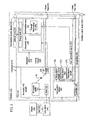
- FIG. 1 illustrates a schematic diagram of an exemplary environmental control system 10 that may be used to control airflow within an aircraft 12.
- Aircraft 12 includes a fuselage 14 having an interior volume 16.
- fuselage 14 includes a passenger area 18, a cargo area 20 and an under floor distribution section 22 positioned between passenger area 18 and cargo area 20.
- an upper floor 24 and a lower floor 26 define a location for floor distribution section 22.
- Passenger area 18 includes an occupancy zone 28, a recirculation zone 30, a mixing zone 32 and an exhaust zone 34.
- occupancy zone 28 requires a higher air quality level than recirculation zone 30.
- occupancy zone 28 may include locations for seating passengers (not shown).
- recirculation zone 30 may include an aisle (not shown) or other volume where passengers are not seated.
- mixing zone 32 is adjacent to occupancy zone 28 and recirculation zone 30.
- Mixing zone 32 is configured to mix air that flows through the occupancy zone 28 and recirculation zone 30 prior to being exhausted from passenger area 18.
- Environmental control system 10 includes an air supply system 40 and an air recirculation system 42.
- Air supply system 40 is coupled in flow communication to passenger area 18 and is configured to supply external air mass 44 into interior volume 16.
- Air recirculation system 42 is coupled in flow communication to floor distribution section 22 and is configured to recirculate air mass 46 within interior volume 16.
- Environmental control system 10 also includes a controller 48 operably coupled to air supply system 40 and air recirculation system 42.
- Controller 48 is configured to provide control signals to air supply system 40 and air recirculation system 42 to provide selected supply flow rates and selected recirculation flow rates to meet various airflow requirements at various locations inside aircraft 12.
- controller 48 can control the supply flow rate and the recirculation flow rate to meet selected Federal Aviation Regulation (FAR) requirements, to meet cooling requirements, to meet occupant comfort requirements, to meet smoke and fume suppression requirements, and/or to minimize occupant exposure to various contaminants.
- controller 48 can control the supply flow rates and the recirculation flow rates to meet selected airflow requirements in a manner that allows fuel efficient operation of aircraft 12.
- FAR Federal Aviation Regulation
- Air supply system 40 includes an air supply device 50, a supply duct 52, and an air supply outlet 54. Moreover, air supply system 40 includes a flow control device 56 such as, but not limited to, a valve coupled in flow communication to supply duct 52 and positioned in between air supply device 50 and air supply outlet 54. In the illustrated example, air supply system 40 is shown coupled to a first engine 58 and a second engine 60, for example a right engine and a left engine respectively. Air supply system 40 can be coupled to a single engine or more than two engines. Air supply system 40 also can be coupled to a compressor (not shown) to bleed air from fuselage 14 without flow communication with engines 58, 60.
- a compressor not shown
- External air supply device 50 is coupled in flow communication to passenger area 18.
- Air supply device 50 is configured to receive external air mass 44 from exterior of aircraft 12 and to provide at least a portion of external air mass 44 through supply duct 52 and air supply outlet 54 and into passenger area 18.
- External air supply device 50 can provide external air mass 44 to passenger area 18 at a variable supply flow rate (e.g., a variable volume flow rate or mass flow rate).
- External air mass 44 can include engine bleed air, for example air extracted from engines 58, 60 and in particular a compressor section (not shown) of engines 58, 60 associated with or carried by aircraft 12.
- air supply system 40 may include a temperature control device 62 such as, but not limited to, an air conditioning pack to facilitate controlling the temperature of external air mass 44 provided to interior volume 16 of aircraft 12.
- air supply system 40 may include a turbine (not shown) and/or a heat exchanger (not shown) that is configured to exchange the heat from bleed air (not shown) with ambient external air mass 44.
- air supply system 40 may include a filtration device 64 such as, but not limited to, an air purification pack that includes one or more filtration elements (not shown) for filtering contaminants (e.g., gaseous and/or particulate contaminants) from at least a portion of external air mass 44 passing through external air supply device 50.
- air supply system 40 may include a VOC/O3 converter 66.
- External air supply device 50 can include a moisture control device (not shown), which can add moisture to at least a portion of external air mass 44 passing though or proximate to external air supply device 50, remove moisture from at least a portion of air passing though or proximate to external air supply device 50, direct dry air to selected location of interior volume 16, and/or direct moist air to a selected location of interior volume 16.
- a moisture control device not shown
- Supply duct 52 may be coupled in flow communication to external air supply device 50.
- Supply duct 52 may be configured to channel external air mass 44 from external air supply device 50 and into interior volume 16.
- Supply duct 52 may include components such as, but not limited to, piping and/or channels.
- supply duct 52 may include any channeling device that can be used to enable environmental control system 10 to function as described herein.
- supply duct 52 is disposed in at least within cargo area 20 and floor distribution section 22. Supply duct 52, however, can be disposed in any portion of fuselage 14 to enable environmental control system 10 to work as described herein.
- air supply outlet 54 is coupled in flow communication to supply duct 52 and coupled to upper floor 24. More particularly, air supply outlet 54 is coupled to upper floor 24 and in flow communication with passenger area 18. Air supply outlet 54 may include a diffuser 68 which is configured to discharge external air mass 44 from supply duct 52 and into at least one of occupancy zone 28, recirculation zone 30 and mixing zone 32. In the exemplary embodiment, air supply outlet 54 is coupled to upper floor 24 and in flow communication to occupancy zone 28. More particularly, air supply outlet 54 is coupled to upper floor 24 and near at least one seat 36 of a plurality of seats 36.
- Air supply outlet 54 may be configured to discharge external air mass 44 into occupancy zone 28 and about and/or around seat 36.
- air supply outlet 54 is coupled to upper floor 24 and in a position underneath seat 36.
- air supply outlet 54 can be coupled in flow communication to fuselage 14 in a position (not shown) near a side of seat 36 and/or on top of seat 36.
- Air supply outlet 54 can be positioned in any position and/or orientation to channel external air mass 44 from supply duct 52 and into occupancy zone 28.
- air supply outlet 54 can be positioned to discharge external air mass 44 around more than one seat 36.
- Diffuser 68 of air supply outlet 54 can be coupled to controller 48 (shown in Fig. 1 ) which is configured to regulate flow of external air mass 44 out of diffuser 68 and into occupancy zone 28.
- Air recirculation system 42 may include a recirculation supply device 70, a recirculation duct 72 and a recirculation outlet 74.
- Recirculation duct 72 is coupled in flow communication to recirculation supply device 70 and to recirculation outlet 74.
- Air recirculation system 42 may further include a filter 76 and an air purifier pack 78.
- air recirculation system 42 may include a heat exchanger 80 coupled to recirculation duct 72 and positioned in between recirculation supply device 70 and recirculation outlet 74.
- Recirculation supply device 70 may be coupled in flow communication to floor distribution section 22 via recirculation duct 72.
- Recirculation supply device 70 may be configured to provide recirculated air mass 46 to interior volume 16 at a variable supply flow rate (e.g., a variable volume flow rate or mass flow rate).
- recirculation supply device 70 is configured to receive air 46 that is present in passenger area 18 and channel air 46 through exhaust zone 34 and into recirculation duct 72.
- Recirculation supply device 70 can include a variable speed recirculation fan (not shown) wherein the rotation speed of the recirculation fan can be varied to provide selected supply flow rates (e.g., flow rates proportional to and/or otherwise associated with the rotation speed of the recirculation fan).
- recirculation supply device 70 can include any recirculation device having a rotating air propulsive element, for example, a bladed fan, a propeller, an impeller, and/or the like.
- air recirculation system 42 may include recirculation supply device 70 coupled to recirculation duct 72 between exhaust zone 34 and cargo area 20 (shown in Figure 1 ).
- Recirculation duct 72 may be coupled in flow communication to recirculation supply device 70 and is coupled in flow communication to floor distribution section 22.
- Recirculation duct 72 may be configured to channel recirculated air mass 46 from recirculation supply device 70, into floor distribution section 22 and into interior volume 16.
- Recirculation duct 72 may include components such as, but not limited to, piping and/or channels.
- recirculation duct 72 can include any channeling device that can be used to enable environmental control system 10 to function as described herein.
- recirculation duct 72 is disposed within at least one of cargo area 20 and exhaust zone 34.
- recirculation duct 72 can be disposed in any portion of fuselage 14 to enable environmental control system 10 to function as described herein.
- Recirculation outlet 74 is coupled in flow communication to floor distribution section 22 which is in flow communication with passenger area 18. More particularly, recirculation outlet 74 includes a diffuser 86 which is configured to discharge air 46 from floor distribution section 22 and into at least one of occupancy zone 28, recirculation zone 30 and mixing zone 32. In the exemplary embodiment, diffuser 86 is coupled in flow communication to recirculation zone 30. More particularly, diffuser 86 is coupled to upper floor 24 and near at least one aisle 38 of the plurality of aisles 38. Diffuser 86 is configured to discharge recirculated air mass 46 into aisle 38 and recirculation zone 30.
- recirculation outlet 74 can be coupled to fuselage 14 in a position (not shown) near a side of aisle 38 and/or on top of aisle 38.
- Recirculation outlet 74 can be positioned in any position and/or orientation to channel recirculated air mass 46 from recirculation duct 72 and into recirculation zone 30.
- Diffuser 86 of recirculation outlet 74 can be coupled to controller 48 (shown in Figure 1 ) which is configured to regulate flow of recirculated air mass 46 out of diffuser 86 and into recirculation zone 30.
- recirculation duct 72 includes a first recirculation duct 88 and a second recirculation duct 90.
- Air recirculation system 42 includes a control duct 92 coupled in flow communication to first recirculation supply duct 52 and in flow communication to second recirculation supply duct 52.
- Control duct 92 is configured to adjust and/or balance flow of recirculated air mass 46 through first recirculation duct 88 and second recirculation duct 90 and/or adjust temperature of recirculation air 46 flowing through first recirculation duct 88 and second recirculation duct 90.
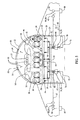
- Figure 4 illustrates a top view of floor distribution section 22.
- a plurality of supply ducts 52 is coupled in flow communication to air supply system 40 and to a plurality of diffusers 68.
- Air supply system 40 is configured to channel external air mass 44 into supply ducts 52 and out of diffusers 68.
- a plurality of recirculation ducts 72 is coupled in flow communication to recirculation air system 42 and to a plurality of diffusers 86.
- Recirculation air system 42 is configured to channel recirculated air mass 46 into recirculation ducts 72 and out of diffusers 68.
- Figure 5 illustrates a schematic diagram of air flows for air supply system 40 and air recirculation system 42.
- external air mass 44 is channeled in through external air supply device 50.
- External air supply device 50 then provides at least a portion of external air mass 44 to interior volume 16 of aircraft 12.
- external air supply device 50 is configured to channel external air mass 44 through supply duct 52 and through air-conditioning pack 62 that compresses external air mass 44 and provides at least a portion of compressed external air mass 44 to interior volume 16 of aircraft 12.
- at least a portion of external air mass 44 can include engine bleed air (e.g., air extracted from a compressor section (not shown) of turbine engine associated with, or carried by, aircraft 12).
- external air mass 44 is channeled through filtration device 64 and VOC/O3 converter 66 via supply duct 52.
- Supply duct 52 is configured to channel external air mass 44 through diffuser 68 of air supply outlet 54 and into occupancy zone 28.
- Air supply system 40 is configured to channel external air mass 44 into occupancy zone 28 to facilitate meeting air quality loading requirements.
- Controller 48 (shown in Figure 1 ) is coupled to flow control device 56 and/or diffuser 68 and is configured to selectively open and close flow control device 56 and/or diffuser 68 to control flow of external air mass 44 from external air supply device 50, through supply duct 52, out of air supply outlet 54 and into occupancy zone 28.
- recirculated air mass 46 is channeled through recirculation supply device 70.
- Recirculation supply device 70 is configured to move recirculated air mass 46 within different portions of interior volume 16 at varying supply flow rates. More particularly, recirculation supply device 70 is configured to channel recirculated air mass 46 through recirculation duct 72 and through associated filters 76 and purifiers 78. Recirculated air mass 46 is then channeled through heat exchanger 80 which is configured to condition the temperature of recirculated air mass 46.
- Recirculation duct 72 is configured to channel recirculated air mass 46 into floor distribution section 22 wherein diffusers 86 of recirculation outlets 74 discharge recirculated air mass 46 from floor distribution section22 and into recirculation zone 30.
- Recirculated air mass 46 then mixes with external air mass 44 that is present in occupancy zone 28 to facilitate forming a mixed air 93 in mixing zone 32.
- Recirculation supply device 70 continues to channel mixed air 93 through exhaust zone 34 and back into recirculation duct 72 to facilitate recirculation of mixed air 93.
- a portion of mixed air 93 is discharged through an outflow control device 94 (shown in Figure 1 ), for example a valve, out of air recirculation system 42.
- Controller 48 (shown in Figure 1 ) is coupled to flow control device 56 and/or diffuser 86 and is configured to selectively open and close flow control device 56 and/or diffuser 86 to control flow of air recirculation from recirculation supply device 70, through recirculation duct 72 and out of recirculation outlet 74.
- airflow pressure of air supply system 44 and airflow pressure of air recirculation system 46 is greater than pressure within passenger area 18 to facilitate channeling external air mass 44 and recirculated air mass 46 into passenger area 18 and to facilitate mixing of external air mass 44 and recirculated air mass 46 in mixing zone 32.
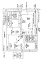
- Figure 6 illustrates a schematic diagram of aircraft 12 and another exemplary environmental control system 96.
- Figure 7 illustrates a top view of floor distribution section 22.
- air supply outlet 54 is coupled in flow communication to floor distribution section 22.
- supply duct 52 includes a floor inlet 98 that is coupled to floor distribution section 22 and in flow communication with floor distribution section 22.
- Floor inlet 98 is configured to discharge external air mass 44 into floor distribution section 22.
- recirculation duct 72 is coupled in flow communication to floor distribution section 22. More particularly, recirculation duct 72 includes a floor inlet 100 that is coupled to lower floor 26 and in flow communication with floor distribution section 22.
- Floor inlet 100 is configured to discharge recirculated air mass 46 into floor distribution section 22.
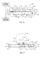
- FIG 8 illustrates another top view of floor distribution section 22.
- Floor distribution section 22 includes a plurality of mixers 102 positioned between upper floor 24 and lower floor 26 (shown in Figure 6 ).
- Each mixer 102 is configured to mix external air mass 44 with recirculated air mass 46 present in floor distribution section 22 to facilitate forming mixed air 104.
- mixer 102 includes a configuration such as, but not limited to, vanes, fins, and columns. Any configuration that mixes external air mass 44 with recirculated air mass 46 can be used that enables environmental control system 10 to function as described herein.
- mixers 102 are positioned offset in a repeating pattern with respect to each other within the floor distribution section 22.
- mixers 102 can be positioned in a non-repeating pattern within floor distribution section 22. Any orientation, pattern and configuration of mixers 102 can be used that enables environmental control system 96 to function as described herein.
- Figure 9 illustrates a side cross sectional view of floor distribution section 22 and a diffuser 106 coupled to floor distribution section 22.
- Environmental control system 96 includes diffuser 106 coupled in flow communication to floor distribution section 22 and in flow communication to passenger area 18.
- Diffuser 106 is configured to discharge mixed air 104 into at least one of occupancy zone 28, recirculation zone 30 and mixing zone 32 (shown in Figure 6 ).
- diffuser 106 is coupled in flow communication to occupancy zone 28. More particularly, diffuser 106 is coupled in flow communication to upper floor 24 and near at least one seat 36 of the plurality of seats 36. Diffuser 106 is configured to discharge mixed air 104 into occupancy zone 28 and about and/or around at least one seat 36.
- diffuser 106 is coupled to upper floor 24 and in a position underneath at least one seat 36.
- diffuser 106 can be located in any position and/or orientation with respect to upper floor 24 and/or passenger area 18 that enables environmental control system 96 to function as described herein.
- Figure 10 illustrates a schematic diagram of exemplary air flows for air supply system 40 and for air recirculation system 42 shown in Figure 6 .
- external air mass 44 is channeled in through external air supply device 50.
- External air supply device 50 then provides at least a portion of external air mass 44 to interior volume 16.
- external air supply device 50 is configured to channel external air mass 44 through supply duct 52 and through air-conditioning pack 62 that compresses external air mass 44 and provides at least a portion of compressed external air mass 44 to interior volume 16.
- at least a portion of external air mass 44 can include engine bleed air (e.g., air extracted from a compressor section (not shown) of turbine engine associated with, or carried by, aircraft 12).
- external air mass 44 is channeled through filtration device 64 and VOC/O3 converter 66.
- External air supply device 50 is configured to channel external air mass 44 through supply duct 52 and through inlet 98 (shown in Figure 6 ) and channeled into floor distribution section 22 via inlet 98.
- recirculated air mass 46 is channeled through recirculation supply device 70. More particularly, recirculation supply device 70 is configured to channel recirculated air mass 46 through recirculation duct 72 and through associated filters 76 and purifiers 78. Recirculated air mass 46 is then channeled through heat exchanger 80 which is configured to condition the temperature of recirculated air mass 46.
- Recirculation duct 72 is configured to channel recirculated air mass 46 through inlet 100 and into floor distribution section 22.
- Floor distribution section 22 is configured to facilitate mixing external air mass 44 and recirculated air mass 46. More particularly, floor distribution section 22 is configured to facilitate mixing external air mass 44 and recirculated air mass 46 to form mixed air 104.
- Mixed air 104 is channeled through diffuser 106 and into occupancy zone 28. Mixed air 104 then mixes with external air mass 44 that is present in occupancy zone 28.
- Recirculation supply device 70 continues to channel mixed air 104 through exhaust zone 34 and back into recirculation duct 72 to facilitate recirculation of mixed air 104.
- a portion of recirculated air mass 46 is discharged through outflow control device 94 (shown in Figure 6 ) out of air recirculation system 42.
- airflow pressure of air supply system 44 and airflow pressure of air recirculation system 46 is greater than pressure within floor distribution section 22 to facilitate channeling external air mass 44 and recirculated air mass 46 into floor distribution section 22 and to facilitate mixing of external air mass 44 and recirculated air mass 46 in floor distribution section 22.
- Figure 11 illustrates a schematic diagram of aircraft 12 and another exemplary environmental control system 108.
- Figure 12 illustrates a top view of floor distribution section 22 shown in Figure 11 .
- Figure 13 illustrates a side cross sectional view of floor distribution section 22 and a mixing plenum 110 of environmental control system 108.
- environmental control system 108 same or similar components of environmental control system 10 (shown in Figures 6-10 ) are designated with the same element numbers as environmental control system 10 (shown in Figures 6-10 ).
- environmental control system 108 includes mixing plenum 110 disposed within floor distribution section 22.
- Mixing plenum 110 includes a top wall 112, bottom wall 114 and sidewalls 116 disposed between top wall 112 and bottom wall 114.
- Top wall 112, bottom wall 114 and side walls 116 are configured to define a closed cavity 118 therein.
- supply duct 52 is coupled in flow communication to mixing plenum 110. More particularly, supply duct 52 includes a plenum inlet 120 that is coupled to bottom wall 114 and in flow communication with cavity 118. Plenum inlet 120 is configured to discharge external air mass 44 into cavity 118.
- recirculation duct 72 is coupled in flow communication to mixing plenum 110. More particularly, recirculation duct 72 includes a plenum inlet 122 that is coupled to bottom wall 114 and in flow communication with cavity 118. Plenum inlet 122 is configured to discharge recirculated air mass 46 into cavity 118.
- Mixing plenum 110 includes a plurality of mixers 102 positioned between top wall 112 and bottom wall 114. Each mixer 102 is configured to mix external air mass 44 with recirculated air mass 46 present in cavity 118 to facilitate forming mixed air 104.
- mixer 102 includes a configuration such as, but not limited to, vanes, fins, and columns. Any configuration that mixes external air mass 44 with recirculated air mass 46 can be used that enables environmental control system 108 to function as described herein.
- mixers 102 are positioned offset in a repeating pattern with respect to each other within mixing plenum 110. Alternatively, mixers 102 can be positioned in a non-repeating pattern within mixing plenum 110. Any orientation, pattern and configuration of mixers 102 can be used that enables environmental control system 108 to function as described herein.
- Environmental control system 108 includes diffuser 106 coupled to mixing plenum 110 and in flow communication to cavity 118 and passenger area 18.
- mixing plenum 110 includes a plurality of outlet ducts 124 coupled in flow communication to each diffuser 106.
- Ducts 124 are configured to channel mixed air 104 from cavity 118 and through diffuser 106.
- Diffuser 106 is configured to discharge mixed air 104 into at least one of occupancy zone 28, recirculation zone 30 and mixing zone 32.
- diffuser 106 is coupled in flow communication to occupancy zone 28. More particularly, diffuser 106 is coupled to top wall 112 and near at least one seat 36 of the plurality of seats 36. Diffuser 106 is configured to discharge mixed air 104 into occupancy zone 28 and about and/or around seat 36.
- diffuser 106 is coupled to upper floor 24 and in a position underneath seat 36.
- Figure 14 illustrates a schematic diagram of exemplary air flows for air supply system 40 and for air recirculation system 42 shown in Figure 11 .
- external air mass 44 is channeled in through external air supply device 50.
- External air supply device 50 then provides at least a portion of external air mass 44 to interior volume 16.
- external air device 50 is configured to channel external air mass 44 through supply duct 52 and through air-conditioning pack 62 that compresses external air mass 44 and provides at least a portion of compressed external air mass 44 to interior volume 16.
- at least a portion of external air mass 44 can include engine bleed air (e.g., air extracted from a compressor section (not shown) of turbine engine associated with, or carried by, aircraft 12).
- external air mass 44 is channeled through filtration devices 64 and VOC/O3 converter 66.
- External air supply device 50 is configured to channel external air mass 44 through supply duct 52 and through plenum inlet 120. External air mass 44 is then channeled into cavity 118 of mixing plenum 110.
- recirculated air mass 46 is channeled through recirculation supply device 70. More particularly, recirculation supply device 70 is configured to channel recirculated air mass 46 through recirculation duct 72 and through associated filters 76 and purifiers 78. Recirculated air mass 46 is then channeled through heat exchanger 80 which is configured to condition the temperature of recirculated air mass 46.
- Recirculation duct 72 is configured to channel recirculated air mass 46 through inlet 122 and into cavity 118 of mixing plenum 110. Cavity 118 and mixers 102 are configured to facilitate mixing external air mass 44 and recirculated air mass 46.
- cavity 118 is configured to facilitate mixing external air mass 44 and recirculated air mass 46 to form mixed air 104.
- Mixed air 104 is channeled through diffuser 106 and into occupancy zone 28.
- Recirculation supply device 70 continues to channel mixed air 104 through exhaust zone 34 and back into recirculation duct 72 to facilitate recirculation of mixed air 104.
- a portion of recirculated air mass 46 is discharged through outflow control device 94 (shown in Figure 11 ), for example a valve, out of air recirculation system 42.
- airflow pressure of air supply system 44 and airflow pressure of air recirculation system 46 is greater than pressure within mixing plenum 110 to facilitate channeling external air mass 44 and recirculated air mass 46 into mixing plenum 110 and to facilitate mixing of external air mass 44 and recirculated air mass 46 in mixing plenum 110.
- FIG 15 illustrates a schematic diagram of aircraft 12 and another exemplary environmental control system 126.
- Figure 16 illustrates a top view of floor distribution section 22 shown in Figure 15 .
- Figure 17 illustrates a side cross sectional view of floor distribution section 22 shown in Figure 15 .
- environmental control system 126 same or similar components of environmental control system 108 (shown in Figures 11-14 ) are designated with the same element numbers as environmental control system 108 (shown in Figures 11-14 ).
- environmental control system 126 includes an auxiliary duct 128 coupled in flow communications to recirculation duct 72 between cargo zone 20 or cargo area 20 and floor distribution section 22. More particularly, auxiliary duct 128 is coupled to recirculation duct 72 between heat exchanger 80 and mixing plenum 110. Moreover, auxiliary duct 128 is coupled in flow communication to an auxiliary location 130 in interior volume 16 such as, but not limited to, a service area.
- Environmental control system 126 includes flow control device 131 such as, for example, variable air volume valve.
- FIG 18 illustrates a schematic diagram of exemplary air flows for the air supply system and for the air recirculation system shown in Figure 15 .
- Controller 48 (shown in Figure 1 ) is coupled to flow control device 131 and is configured to selectively open and close flow control device 131 to control flow of air recirculation from recirculation duct 72 through auxiliary duct 28 and into auxiliary location 130.
- Flow control device 132 is configured to control the rate of recirculated air mass 46 into auxiliary duct 128 based on at least thermal loading of interior volume 16 and flight condition.
- air supply system 40 is configured to channel external air mass 44 into mixing plenum 110 and air recirculation system 42 is configured to channel recirculated air mass 46 into mixing plenum 110 to facilitate forming mixed air 104 as previously described.
- Figure 19 illustrates a cross sectional view of fuselage 14 and another environmental control system 132 disposed within fuselage 14.
- Environmental control system 132 includes at least one air flow device 134 that is coupled in flow communication to exhaust zone 34 and to cargo area 20, wherein at least one fan 136 is coupled to air flow device 134.
- air flow device 134 includes a channel structure such as, but not limited to, a pipe, duct and/or vent.
- Air flow device 134 and fan 136 are configured to facilitate controlling pressure differences among passenger area 18, cargo area 20 and exhaust zone 34. More particularly, air flow device 134 and fan 136 are configured to control flow of recirculated air mass 46 from passenger area 18 into exhaust zone 34 and into cargo area 20.
- environmental control systems 10, 96, 108, and 126 disclosed herein may include environmental control system 132 which is configured to handle cabin decompressions that may occur from undetected metal fatigue that can remove a portion of the vehicle's skin (not shown) in midair with a small hole in fuselage.
- Figure 20 illustrates a flowchart for an exemplary method 2000 for environmentally controlling interior volume 16 of aircraft 12 having floor distribution section that is coupled in fluid communication to occupancy zone and recirculation zone, such as for example occupancy zone 28 and recirculation zone 30 (shown in Figure 1 ).
- Method includes directing 2010 external air, for example external air mass 44, into an air supply system such as air supply system 40 (shown in Figure 2 ).
- recirculated air for example recirculated air mass 46 is directed 2020 into an air recirculation system such as air recirculation system 42 (shown in Figure 3 ).
- Method 2000 includes channeling 2030 the external air into the occupancy zone and channeling 2040 the recirculated air into the mixing zone.
- method 2000 includes mixing 2050 the external air and the recirculated air in the mixing zone to facilitate generating a mixed air, for example mixed air 104 (shown in Figure 5 ).
- the mixed air is channeling mixed 2060 air into the air recirculation system.
- an aircraft 12 including: a fuselage 14 comprising a passenger area 18 having an occupancy zone 28 and a recirculation zone 30; a floor distribution section 22 coupled in flow communication to said occupancy zone 28 and said recirculation zone 30; an air supply system 40 coupled to said aircraft 12, said air supply system 40 comprising: an air supply device 50 coupled to said fuselage 14; a supply duct 52 coupled in flow communication to said air supply device 50; and an air supply outlet 54 coupled in flow communication to said supply duct 52 and in flow communication with at least one of said occupancy zone 28 and said floor distribution section 22; and an air recirculation system 42 coupled to said aircraft 12, said air recirculation system 42 comprising: a recirculation supply device 70 coupled to said fuselage 14; a recirculation duct 72 coupled in flow communication to said recirculated supply device 70 and coupled to said floor distribution section 22; and a recirculation outlet 74 coupled in flow communication to said recirculation duct 72 and in flow communication with at least
- the aircraft includes wherein said air supply outlet 54 is coupled in flow communication to the occupancy zone 28. In another variant, the aircraft includes wherein said recirculation outlet 74 is coupled in flow communication to the recirculation zone 30. In still another variant, the aircraft includes wherein said air supply system 40 and said recirculation system 42 are coupled in flow communication to the floor distribution section 22. In yet another variant, the aircraft further includes a mixer 102 coupled to the floor distribution section 22. In still another variant, the aircraft further includes a mixing plenum 110 coupled to the floor distribution section 22, said mixing plenum 110 is configured to mix external air mass from said air supply system 40 with recirculated air mass from said air recirculation system 42.
- the aircraft further includes a mixer 102 coupled to said mixing plenum 118.
- the aircraft includes wherein said supply duct 50 and said recirculation duct 72 are coupled in flow communication to said mixing plenum 110.
- the aircraft further includes a plurality of ducts coupled in flow communication to said mixing plenum 110 and to said occupancy zone 28, said plurality of ducts configured to channel a mixed air mass into said occupancy zone 28.
- the aircraft further includes a flow control device 131 coupled to at least one duct of said plurality of ducts.
- the aircraft further includes an auxiliary duct 128 coupled in flow communication to said recirculation duct 72 and comprising a flow control device 131 coupled in flow communication to said auxiliary duct 128.
- the aircraft 12 further includes a cargo zone 20, an exhaust zone 34 and an airflow device 134 coupled in flow communication to said cargo zone 20 and said exhaust zone 34.
- an environmental control system 132 for use with an aircraft 12 having a floor distribution section 22 that is coupled in flow communication to an occupancy zone 28 and a recirculation zone 30, said environmental control system 126 comprising: an air supply system 40 coupled to the aircraft 12, the air supply system 40 comprising: an air supply device 50 coupled to the aircraft 12; a supply duct 52 coupled in flow communication to said air supply device 50; and an air supply outlet 54 coupled in flow communication to said supply duct 52 and in flow communication with at least one of the occupancy zone 28 and the floor distribution section 22; and an air recirculation system 42 coupled to the aircraft 12, the air recirculation system 42 comprising: a recirculation supply device 70 coupled to the aircraft 12; a recirculation duct 72 coupled in flow communication to said recirculated supply device 70 and coupled to the floor distribution section 22; and a recirculation outlet 74 coupled in flow communication to said recirculation duct 72 and in flow communication with at least one of the recirculation zone 30 and the floor distribution section 22.
- the environmental control system 132 further comprising a heat exchanger coupled to said recirculation duct 72.
- the environmental control system 132 further includes a controller operatively coupled to said air supply system 40 and said air recirculation system 42.
- the environmental control system 132 includes wherein said air supply outlet 54 is coupled in flow communication to the occupancy zone 28 and said recirculation outlet 34 is coupled in flow communication with the recirculation zone 30.
- the environmental control system 132 includes wherein said air supply system 40 and said recirculation system 42 are coupled in flow communication to the floor distribution section 22.
- the environmental control system 132 further includes a mixing plenum 110 coupled to the floor distribution section 22, said mixing plenum 110 is configured to mix external air mass from said air supply system 40 with recirculated air mass from said air recirculation system 42.
- the environmental control system 132 further includes a plurality of ducts coupled in flow communication to said mixing plenum 110 and to said occupancy zone 28, said plurality of ducts configured to channel a mixed air mass into said occupancy zone 28.
- a method of controlling airflow is disclosed within an aircraft 12 having a floor distribution section 22 that is coupled in fluid communication to an occupancy zone 28, a recirculation and a mixing zone, the method comprising: directing external air into an air supply system 40; directing recirculated air into an air recirculation system 42; channeling the external air into the occupancy zone 28; channeling the recirculated air into the recirculation zone 30; mixing the external air and the recirculated air in the mixing zone to facilitate forming a mixed air; and channeling the mixed air into the air recirculation system 42.
- the method further includes directing the external air and the recirculated air into the floor distribution section 22. In another variant, the method further includes mixing the external air and the recirculated air in the floor distribution section 22. In still another variant, the method further includes directing the external air and the recirculated air into a mixing plenum 110 that is located in the floor distribution section 22 and mixing the external air and the recirculated air within the mixing plenum 110. In one example, the method further includes channeling the recirculated air into an auxiliary duct 128.
- flow rate of air near occupant includes parameters such as, but not limited to, from about 0.35lb/occy./min to about 0.75lb/occy./min; from about 7CFM to about 10CFM per seat; outlet velocity from about .3 ft/s to about 1.8 ft/s (from about 0.1 m/s to about 0.55 m/s); temperature from about 60° F to about 80° F +/- 5° F; and humidity from about 10% to about 20%.
- flow rate of air includes parameters such as, but not limited to, 0.55 lb/occy./min; temperature of about 75°F; outlet velocity less than about 0.66 ft/s (.2m/s) and humidity from about 10% to 20%.
- the size and location of outlets and diffusers can be adjustable for different air flow velocity.
- outlets are configured are to minimize and/or eliminate large temperature differences and drafts within interior volume.
- air recirculation system is configured to remove thermal loading from components, for example power feeders, in floor distribution section and/or cargo area.
- the embodiments disclosed herein are configured to minimize and/or eliminate smoke penetration. More particularly, the embodiments disclosed herein are configured to maintain cabin pressure higher than cargo pressure to facilitate maintaining any smoke in cargo area.
- the embodiments disclosed herein include smoke and/or pressure sensors to monitor pressure differences and to control and/or adjust cabin/cargo air flow rates based on pressure differences to facilitate reducing and/or eliminating smoke penetration into cabin area.
- the embodiments disclosed herein can operate with and/or without heat exchangers.
- controller can be distributed among multiple components and can include portions of a computer or computing system, mechanical devices, electromechanical devices, and/or the like.
- controller can be programmed with instructions for determining required supply flow rate(s) and/or recirculation flow rate(s) based on operational conditions/considerations. Controller can then command air supply system and/or air recirculation system to provide at least approximately the determined supply flow rate(s) and/or recirculation flow rate(s), respectively. Additionally, controller can vary the supply flow rate(s) and/or recirculation rate(s) as operational conditions change.
- Controller can also be operably coupled to flow control devices via a signal pathway (not shown) and can control the supply flow rate and flow control devices to control pressurization as vehicle climbs and descends.
- Flow control devices can be configured to control the release of exhaust air from vehicle.
- Controller can be configured to control the supply flow rate (e.g., external air entering interior of vehicle) and flow control devices to provide a selected pressure in interior and/or a selected pressure differential between the interior and exterior of vehicle.
- controller can vary the supply flow rate based on the number of vehicle occupants that are carried on vehicle. For instance, governmental regulations may require a minimum external airflow rate per occupant to during flight. In still other embodiments, the supply flow rate can be varied to ensure adequate thermal control, adequate equipment cooling, adequate cargo exhaust, adequate lavatory exhaust, adequate galley exhaust, and/or adequate smoke suppression/evacuation in a smoke event. Controller can use stored information, sensed information, information provided by an operator, and/or information supplied by a data link to determine flow rate requirements.
- controller can vary the recirculation flow rate in response to variations in the supply flow rate and/or based on various operational conditions/considerations similar to those discussed above. For example, in the exemplary embodiment, controller can vary the recirculation flow rate as the supply flow rate is increased or decreased so that the total flow rate (e.g., volumetric or mass flow rate) at selected locations remains at least approximately constant. In certain embodiments where air recirculation device includes a variable speed recirculation fan, controller can determine the rotation speed of the recirculation fan to provide at least approximately a desired recirculation flow rate and control/command the rotation speed of recirculation fan accordingly.
- this feature can allow a reduction in external air requirements, thereby increasing vehicle fuel economy while maintaining desirable cabin flow rates via the increase in recirculation flow rates.
- controller can reduce the supply flow rate and increase the recirculation flow rate during selected phases of flight and/or above selected altitudes to improve fuel economy.
- environmental control systems include sensors (not shown) which are configured to sense various characteristics associated with air in vehicle interior.
- sensors can be configured to sense air pressure, airflow rates (e.g., volumetric flow rates and/or mass flow rates), air temperature, air humidity, and/or airborne contaminants (e.g., including particulate contaminants, gaseous contaminants, biological elements, and/or chemical elements).
- controller can be configured to adjust the supply flow rate and/or the recirculation flow rate in response to one or more characteristics sensed by sensors. For example, in selected embodiments, controller can increase the supply flow rate (e.g., and external air entering interior of vehicle) if sensor(s) detect that a selected concentration of a selected contaminant (e.g., CO and/or CO 2 ) has been met or exceeded in order to reduce the concentration of the contaminant in interior. In other embodiments, controller can decrease the supply flow rate and send signal to flight deck or maintenance station for VOC/O3 converter checking if excessive O 3 is sensed in interior of vehicle to decrease the concentration of O 3 .
- a selected contaminant e.g., CO and/or CO 2
- controller can increase supply flow rates, increase the release of exhaust air through flow control devices, and decrease or cease the flow of air recirculation in the event of certain smoke conditions to evacuate smoke from interior of vehicle.
- controller can increase the supply flow rate to increase equipment cooling in the event that excessive temperatures are sensed in the electronics bay location and/or on selected electronic components.
- controller can use the combination of supply flow rate and recirculation flow rate to aid in temperature control and/or pressurization control of interior of vehicle.
- the thermal loading (cooling/heating loading) for commercial airplane are dynamically changing in terms of the different flight and ground conditions.
- the thermal loadings include: heating or cooling loads from ambient through the fuselage; lighting; occupancy; electronics bay, IFE and other electrical devices etc.
- the embodiments described herein are configured to remove these thermal loadings.
Landscapes
- Health & Medical Sciences (AREA)
- General Health & Medical Sciences (AREA)
- Pulmonology (AREA)
- Engineering & Computer Science (AREA)
- Aviation & Aerospace Engineering (AREA)
- Ventilation (AREA)
- Air-Conditioning For Vehicles (AREA)
- Central Air Conditioning (AREA)
Applications Claiming Priority (1)
| Application Number | Priority Date | Filing Date | Title |
|---|---|---|---|
| US13/490,270 US9889939B2 (en) | 2012-06-06 | 2012-06-06 | Environmental control system and methods of operating same |
Publications (3)
| Publication Number | Publication Date |
|---|---|
| EP2671801A2 true EP2671801A2 (de) | 2013-12-11 |
| EP2671801A3 EP2671801A3 (de) | 2018-01-31 |
| EP2671801B1 EP2671801B1 (de) | 2022-08-03 |
Family
ID=48625768
Family Applications (1)
| Application Number | Title | Priority Date | Filing Date |
|---|---|---|---|
| EP13170683.0A Active EP2671801B1 (de) | 2012-06-06 | 2013-06-05 | Klimaanlage und verfahren zu deren betrieb |
Country Status (4)
| Country | Link |
|---|---|
| US (1) | US9889939B2 (de) |
| EP (1) | EP2671801B1 (de) |
| JP (1) | JP6261192B2 (de) |
| ES (1) | ES2928741T3 (de) |
Cited By (3)
| Publication number | Priority date | Publication date | Assignee | Title |
|---|---|---|---|---|
| CN106553758A (zh) * | 2015-09-18 | 2017-04-05 | 霍尼韦尔国际公司 | 使用超细颗粒物检测和测量以控制向航空器机舱环境的空气供给系统污染物递送的方法 |
| EP3466815A1 (de) * | 2017-10-04 | 2019-04-10 | The Boeing Company | Raumfahrzeugklimaregelungssystem |
| EP3922561A1 (de) * | 2020-06-09 | 2021-12-15 | Honeywell International Inc. | Verwendung von kohlendioxidsensoren zur steuerung der belüftung von flugzeugen |
Families Citing this family (30)
| Publication number | Priority date | Publication date | Assignee | Title |
|---|---|---|---|---|
| US20140352913A1 (en) * | 2013-05-31 | 2014-12-04 | Hamilton Sundstrand Corporation | Aircraft refrigeration unit evaporator heater |
| US9581163B2 (en) * | 2013-08-27 | 2017-02-28 | The Boeing Company | Air diffuser systems, methods, and apparatuses |
| US10081429B2 (en) | 2014-07-21 | 2018-09-25 | The Boeing Company | Air diffuser systems, methods, and apparatuses |
| US9957052B2 (en) | 2015-01-27 | 2018-05-01 | Honeywell International Inc. | Aircraft environmental control system that optimizes the proportion of outside air from engines, APU's, ground air sources and the recirculated cabin air to maintain occupant comfort and maximize fuel economy |
| US9776725B2 (en) | 2015-01-27 | 2017-10-03 | Honeywell International Inc. | Human factors approach to control contaminant concentrations in aircraft supply air from engine and APU bleed air and ground air sources, and in recirculated air being delivered to aircraft cabins for the optimization of user experience and energy consumption |
| DE102015203170B4 (de) * | 2015-02-23 | 2021-09-09 | Airbus Operations Gmbh | Verfahren und System zur Steuerung einer Klimaanlage zur Klimatisierung eines Flugzeugfrachtraums |
| US9580178B2 (en) | 2015-05-01 | 2017-02-28 | The Boeing Company | Methods and apparatuses for integrated noise control and flow control in an aircraft environmental control system |
| CN107635874B (zh) * | 2015-05-22 | 2020-10-16 | 庞巴迪公司 | 飞行器空气质量监控系统和方法 |
| US10814988B2 (en) | 2015-06-08 | 2020-10-27 | Hamilton Sunstrand Corporation | Unequal bleed flow |
| US20180224145A1 (en) * | 2015-07-27 | 2018-08-09 | Sharp Kabushiki Kaisha | Air-conditioning system and carbon dioxide absorbing unit |
| CN105292493B (zh) * | 2015-10-30 | 2018-04-03 | 天津大学 | 适用于民用客机座舱的具有下送上回气流通道的空调系统 |
| EP3176089B1 (de) * | 2015-12-02 | 2019-02-06 | Airbus Operations GmbH | Kabinenluftsteuerungssystem für ein flugzeug |
| US10479510B2 (en) * | 2016-10-12 | 2019-11-19 | The Boeing Company | Modular environmental control chamber |
| US11820518B2 (en) * | 2016-12-05 | 2023-11-21 | Clark C. Hampe, JR. | Airflow diverter for aircraft and method of use |
| FR3070036A1 (fr) * | 2017-08-08 | 2019-02-15 | Airbus Operations | Aeronef comprenant un dispositif de conditionnement d'air positionne dans la pointe avant de l'aeronef |
| US10703170B2 (en) * | 2017-10-03 | 2020-07-07 | Ford Global Technologies, Llc | Tire smoke induction prevention system for a motor vehicle |
| EP3587267A1 (de) | 2018-06-29 | 2020-01-01 | United Technologies Research Centre Ireland | Klimaanlage |
| US11554634B2 (en) * | 2019-10-01 | 2023-01-17 | The Boeing Company | Vehicle air handling system for apportioning airflow between passenger and cargo compartments |
| EP3808658B1 (de) * | 2019-10-14 | 2024-07-31 | Hamilton Sundstrand Corporation | Klimasteuerungsanlage |
| US11383842B2 (en) | 2019-10-18 | 2022-07-12 | The Boeing Company | Ventilated vehicle seat systems and methods |
| US12042764B2 (en) * | 2020-05-11 | 2024-07-23 | Hamilton Sundstrand Corporation | Aircraft air management systems for deactivating contaminants |
| US20210387737A1 (en) * | 2020-06-10 | 2021-12-16 | Walter Dorwin Teague Associates, Inc. | Passenger air shield |
| US20210394911A1 (en) * | 2020-06-19 | 2021-12-23 | The Boeing Company | Methods and systems for decontaminating aircraft cabins and providing indications for safe reentry |
| US11851205B2 (en) * | 2020-07-06 | 2023-12-26 | Honeywell International Inc. | Air quality monitoring |
| JP2022022105A (ja) | 2020-07-23 | 2022-02-03 | ザ・ボーイング・カンパニー | 航空機で使用するための給気システム |
| US11958616B2 (en) | 2020-09-09 | 2024-04-16 | The Boeing Company | Air distribution nozzles, aircraft that include air distribution nozzles, and methods of utilizing air distribution nozzles |
| US11884403B2 (en) | 2020-09-09 | 2024-01-30 | The Boeing Company | Air distribution nozzles, aircraft that include air distribution nozzles, and methods of utilizing air distribution nozzles |
| US20220135235A1 (en) * | 2020-10-29 | 2022-05-05 | The Boeing Company | Ventilation systems and methods for internal cabins of vehicles |
| EP4008636B1 (de) | 2020-12-03 | 2024-05-01 | The Boeing Company | Flugzeugklimaregelungssystem mit luftstrom-schichtern und verfahren zur steuerung des luftstroms in einem flugzeug |
| US12065250B2 (en) * | 2020-12-09 | 2024-08-20 | Hamilton Sundstrand Corporation | Recirculation ground maintenance mode |
Family Cites Families (11)
| Publication number | Priority date | Publication date | Assignee | Title |
|---|---|---|---|---|
| US4742760A (en) * | 1987-07-06 | 1988-05-10 | The Boeing Company | Aircraft cabin ventilation system |
| JPH0828945A (ja) * | 1994-07-13 | 1996-02-02 | Ryoko:Kk | 吹出口機構、及びそれを備えたパーティションユニット |
| DE4425871C2 (de) * | 1994-07-21 | 1998-07-02 | Daimler Benz Aerospace Airbus | Verfahren zum Klimatisieren von zwei Passagierdecks eines Flugzeuges, insbesondere eines Großraumflugzeuges, und Einrichtung zur Durchführung des Verfahrens |
| JP2888479B2 (ja) | 1995-02-28 | 1999-05-10 | 株式会社イナックス | 吸水口カバー |
| JPH10109644A (ja) * | 1996-10-07 | 1998-04-28 | Nippon Sharyo Seizo Kaisha Ltd | 鉄道車両用空調システム |
| US5897079A (en) * | 1997-08-18 | 1999-04-27 | Mcdonnell Douglas Corporation | Air curtain insulating system for aircraft cabin |
| US7789346B2 (en) * | 2006-09-29 | 2010-09-07 | The Boeing Company | Cabin air supply apparatus with filtered air |
| US7871038B2 (en) | 2007-05-17 | 2011-01-18 | The Boeing Company | Systems and methods for providing airflow in an aerospace vehicle |
| DE102007049926A1 (de) * | 2007-10-18 | 2009-04-23 | Airbus Deutschland Gmbh | System und Verfahren zur Klimatisierung zumindest eines Teilbereichs eines Flugzeugs |
| EP2356026B1 (de) | 2008-12-12 | 2015-02-18 | Liebherr-Aerospace Lindenberg GmbH | Notenergiesystem für ein luftfahrzeug |
| DE102010012143A1 (de) * | 2010-03-20 | 2011-09-22 | Fraunhofer-Gesellschaft zur Förderung der angewandten Forschung e.V. | Flugzeug und Verfahren zur Klimatisierung zumindest eines Teilbereiches des Innenraumes eines Flugzeuges |
-
2012
- 2012-06-06 US US13/490,270 patent/US9889939B2/en active Active
-
2013
- 2013-06-04 JP JP2013118133A patent/JP6261192B2/ja active Active
- 2013-06-05 ES ES13170683T patent/ES2928741T3/es active Active
- 2013-06-05 EP EP13170683.0A patent/EP2671801B1/de active Active
Non-Patent Citations (1)
| Title |
|---|
| None |
Cited By (5)
| Publication number | Priority date | Publication date | Assignee | Title |
|---|---|---|---|---|
| CN106553758A (zh) * | 2015-09-18 | 2017-04-05 | 霍尼韦尔国际公司 | 使用超细颗粒物检测和测量以控制向航空器机舱环境的空气供给系统污染物递送的方法 |
| EP3466815A1 (de) * | 2017-10-04 | 2019-04-10 | The Boeing Company | Raumfahrzeugklimaregelungssystem |
| US10737791B2 (en) | 2017-10-04 | 2020-08-11 | The Boeing Company | Aerospace vehicle environmental control system |
| EP3922561A1 (de) * | 2020-06-09 | 2021-12-15 | Honeywell International Inc. | Verwendung von kohlendioxidsensoren zur steuerung der belüftung von flugzeugen |
| US11643215B2 (en) | 2020-06-09 | 2023-05-09 | Honeywell International Inc. | Use of carbon dioxide sensors for aircraft ventilation control |
Also Published As
| Publication number | Publication date |
|---|---|
| US9889939B2 (en) | 2018-02-13 |
| JP6261192B2 (ja) | 2018-01-17 |
| EP2671801B1 (de) | 2022-08-03 |
| EP2671801A3 (de) | 2018-01-31 |
| ES2928741T3 (es) | 2022-11-22 |
| US20130327891A1 (en) | 2013-12-12 |
| JP2013252851A (ja) | 2013-12-19 |
Similar Documents
| Publication | Publication Date | Title |
|---|---|---|
| US9889939B2 (en) | Environmental control system and methods of operating same | |
| US7871038B2 (en) | Systems and methods for providing airflow in an aerospace vehicle | |
| EP2918497B1 (de) | Turboladersystem und Verfahren zur Extraktion von Energie aus einem Flugzeugtriebwerk | |
| US7837541B2 (en) | Method for reducing outside air inflow required for aircraft cabin air quality | |
| US8074927B2 (en) | System for improving air quality in an aircraft pressure cabin | |
| US8571726B2 (en) | Method for reducing outside air inflow required for aircraft cabin air quality | |
| CA2845141C (en) | Aircraft air supply system for reducing an effective altitude of a flight deck | |
| US20130040546A1 (en) | Aircraft and method for climatizing at least a part-region of the interior of an aircraft | |
| US20040231350A1 (en) | Compact air conditioning mixer system | |
| JP5559806B2 (ja) | 空気混合機周辺のリークの場合の航空機キャビンの緊急換気方法及びそのシステム | |
| CN105292493B (zh) | 适用于民用客机座舱的具有下送上回气流通道的空调系统 | |
| US20090095004A1 (en) | System for producing air | |
| US10392122B2 (en) | Inerting system and method for an aircraft using exhaust air | |
| CN103249643B (zh) | 具有受调节的冷源的飞行器环境控制系统 | |
| EP3718898A1 (de) | Wiederverwendung von mit verbrauchtem sauerstoff angereicherter luft in einem flugzeug | |
| US20190161196A1 (en) | Air-Conditioning System For An Aircraft | |
| EP1155958B2 (de) | Kühlsystem für ein Fluggastunterhaltungssystem (IFE) | |
| National Research Council | Environmental Control | |
| CN113879543B (zh) | 一种飞机通风系统及包括该飞机通风系统的飞机 | |
| Cavalcanti et al. | A trade-off study of a bleedless and conventional air conditioning systems | |
| Cavalcanti et al. | SAE TECHNICAL 2008-36-0001 PAPER SERIES E | |
| National Research Council | Environmental Control Systems on Commercial Passenger Aircraft |
Legal Events
| Date | Code | Title | Description |
|---|---|---|---|
| PUAI | Public reference made under article 153(3) epc to a published international application that has entered the european phase |
Free format text: ORIGINAL CODE: 0009012 |
|
| 17P | Request for examination filed |
Effective date: 20130605 |
|
| AK | Designated contracting states |
Kind code of ref document: A2 Designated state(s): AL AT BE BG CH CY CZ DE DK EE ES FI FR GB GR HR HU IE IS IT LI LT LU LV MC MK MT NL NO PL PT RO RS SE SI SK SM TR |
|
| AX | Request for extension of the european patent |
Extension state: BA ME |
|
| PUAL | Search report despatched |
Free format text: ORIGINAL CODE: 0009013 |
|
| AK | Designated contracting states |
Kind code of ref document: A3 Designated state(s): AL AT BE BG CH CY CZ DE DK EE ES FI FR GB GR HR HU IE IS IT LI LT LU LV MC MK MT NL NO PL PT RO RS SE SI SK SM TR |
|
| AX | Request for extension of the european patent |
Extension state: BA ME |
|
| RIC1 | Information provided on ipc code assigned before grant |
Ipc: B64D 13/08 20060101AFI20171222BHEP Ipc: B64D 13/06 20060101ALI20171222BHEP |
|
| STAA | Information on the status of an ep patent application or granted ep patent |
Free format text: STATUS: EXAMINATION IS IN PROGRESS |
|
| STAA | Information on the status of an ep patent application or granted ep patent |
Free format text: STATUS: EXAMINATION IS IN PROGRESS |
|
| 17Q | First examination report despatched |
Effective date: 20210112 |
|
| STAA | Information on the status of an ep patent application or granted ep patent |
Free format text: STATUS: EXAMINATION IS IN PROGRESS |
|
| GRAP | Despatch of communication of intention to grant a patent |
Free format text: ORIGINAL CODE: EPIDOSNIGR1 |
|
| STAA | Information on the status of an ep patent application or granted ep patent |
Free format text: STATUS: GRANT OF PATENT IS INTENDED |
|
| INTG | Intention to grant announced |
Effective date: 20220216 |
|
| GRAS | Grant fee paid |
Free format text: ORIGINAL CODE: EPIDOSNIGR3 |
|
| GRAA | (expected) grant |
Free format text: ORIGINAL CODE: 0009210 |
|
| STAA | Information on the status of an ep patent application or granted ep patent |
Free format text: STATUS: THE PATENT HAS BEEN GRANTED |
|
| AK | Designated contracting states |
Kind code of ref document: B1 Designated state(s): AL AT BE BG CH CY CZ DE DK EE ES FI FR GB GR HR HU IE IS IT LI LT LU LV MC MK MT NL NO PL PT RO RS SE SI SK SM TR |
|
| REG | Reference to a national code |
Ref country code: AT Ref legal event code: REF Ref document number: 1508556 Country of ref document: AT Kind code of ref document: T Effective date: 20220815 Ref country code: CH Ref legal event code: EP |
|
| REG | Reference to a national code |
Ref country code: DE Ref legal event code: R096 Ref document number: 602013082204 Country of ref document: DE |
|
| REG | Reference to a national code |
Ref country code: IE Ref legal event code: FG4D |
|
| REG | Reference to a national code |
Ref country code: ES Ref legal event code: FG2A Ref document number: 2928741 Country of ref document: ES Kind code of ref document: T3 Effective date: 20221122 |
|
| REG | Reference to a national code |
Ref country code: LT Ref legal event code: MG9D |
|
| REG | Reference to a national code |
Ref country code: NL Ref legal event code: MP Effective date: 20220803 |
|
| PG25 | Lapsed in a contracting state [announced via postgrant information from national office to epo] |
Ref country code: SE Free format text: LAPSE BECAUSE OF FAILURE TO SUBMIT A TRANSLATION OF THE DESCRIPTION OR TO PAY THE FEE WITHIN THE PRESCRIBED TIME-LIMIT Effective date: 20220803 Ref country code: RS Free format text: LAPSE BECAUSE OF FAILURE TO SUBMIT A TRANSLATION OF THE DESCRIPTION OR TO PAY THE FEE WITHIN THE PRESCRIBED TIME-LIMIT Effective date: 20220803 Ref country code: PT Free format text: LAPSE BECAUSE OF FAILURE TO SUBMIT A TRANSLATION OF THE DESCRIPTION OR TO PAY THE FEE WITHIN THE PRESCRIBED TIME-LIMIT Effective date: 20221205 Ref country code: NO Free format text: LAPSE BECAUSE OF FAILURE TO SUBMIT A TRANSLATION OF THE DESCRIPTION OR TO PAY THE FEE WITHIN THE PRESCRIBED TIME-LIMIT Effective date: 20221103 Ref country code: NL Free format text: LAPSE BECAUSE OF FAILURE TO SUBMIT A TRANSLATION OF THE DESCRIPTION OR TO PAY THE FEE WITHIN THE PRESCRIBED TIME-LIMIT Effective date: 20220803 Ref country code: LV Free format text: LAPSE BECAUSE OF FAILURE TO SUBMIT A TRANSLATION OF THE DESCRIPTION OR TO PAY THE FEE WITHIN THE PRESCRIBED TIME-LIMIT Effective date: 20220803 Ref country code: LT Free format text: LAPSE BECAUSE OF FAILURE TO SUBMIT A TRANSLATION OF THE DESCRIPTION OR TO PAY THE FEE WITHIN THE PRESCRIBED TIME-LIMIT Effective date: 20220803 Ref country code: FI Free format text: LAPSE BECAUSE OF FAILURE TO SUBMIT A TRANSLATION OF THE DESCRIPTION OR TO PAY THE FEE WITHIN THE PRESCRIBED TIME-LIMIT Effective date: 20220803 |
|
| REG | Reference to a national code |
Ref country code: AT Ref legal event code: MK05 Ref document number: 1508556 Country of ref document: AT Kind code of ref document: T Effective date: 20220803 |
|
| PG25 | Lapsed in a contracting state [announced via postgrant information from national office to epo] |
Ref country code: PL Free format text: LAPSE BECAUSE OF FAILURE TO SUBMIT A TRANSLATION OF THE DESCRIPTION OR TO PAY THE FEE WITHIN THE PRESCRIBED TIME-LIMIT Effective date: 20220803 Ref country code: IS Free format text: LAPSE BECAUSE OF FAILURE TO SUBMIT A TRANSLATION OF THE DESCRIPTION OR TO PAY THE FEE WITHIN THE PRESCRIBED TIME-LIMIT Effective date: 20221203 Ref country code: HR Free format text: LAPSE BECAUSE OF FAILURE TO SUBMIT A TRANSLATION OF THE DESCRIPTION OR TO PAY THE FEE WITHIN THE PRESCRIBED TIME-LIMIT Effective date: 20220803 Ref country code: GR Free format text: LAPSE BECAUSE OF FAILURE TO SUBMIT A TRANSLATION OF THE DESCRIPTION OR TO PAY THE FEE WITHIN THE PRESCRIBED TIME-LIMIT Effective date: 20221104 |
|
| RAP4 | Party data changed (patent owner data changed or rights of a patent transferred) |
Owner name: THE BOEING COMPANY |
|
| PG25 | Lapsed in a contracting state [announced via postgrant information from national office to epo] |
Ref country code: SM Free format text: LAPSE BECAUSE OF FAILURE TO SUBMIT A TRANSLATION OF THE DESCRIPTION OR TO PAY THE FEE WITHIN THE PRESCRIBED TIME-LIMIT Effective date: 20220803 Ref country code: RO Free format text: LAPSE BECAUSE OF FAILURE TO SUBMIT A TRANSLATION OF THE DESCRIPTION OR TO PAY THE FEE WITHIN THE PRESCRIBED TIME-LIMIT Effective date: 20220803 Ref country code: DK Free format text: LAPSE BECAUSE OF FAILURE TO SUBMIT A TRANSLATION OF THE DESCRIPTION OR TO PAY THE FEE WITHIN THE PRESCRIBED TIME-LIMIT Effective date: 20220803 Ref country code: CZ Free format text: LAPSE BECAUSE OF FAILURE TO SUBMIT A TRANSLATION OF THE DESCRIPTION OR TO PAY THE FEE WITHIN THE PRESCRIBED TIME-LIMIT Effective date: 20220803 Ref country code: AT Free format text: LAPSE BECAUSE OF FAILURE TO SUBMIT A TRANSLATION OF THE DESCRIPTION OR TO PAY THE FEE WITHIN THE PRESCRIBED TIME-LIMIT Effective date: 20220803 |
|
| REG | Reference to a national code |
Ref country code: DE Ref legal event code: R097 Ref document number: 602013082204 Country of ref document: DE |
|
| PG25 | Lapsed in a contracting state [announced via postgrant information from national office to epo] |
Ref country code: SK Free format text: LAPSE BECAUSE OF FAILURE TO SUBMIT A TRANSLATION OF THE DESCRIPTION OR TO PAY THE FEE WITHIN THE PRESCRIBED TIME-LIMIT Effective date: 20220803 Ref country code: EE Free format text: LAPSE BECAUSE OF FAILURE TO SUBMIT A TRANSLATION OF THE DESCRIPTION OR TO PAY THE FEE WITHIN THE PRESCRIBED TIME-LIMIT Effective date: 20220803 |
|
| PLBE | No opposition filed within time limit |
Free format text: ORIGINAL CODE: 0009261 |
|
| STAA | Information on the status of an ep patent application or granted ep patent |
Free format text: STATUS: NO OPPOSITION FILED WITHIN TIME LIMIT |
|
| P01 | Opt-out of the competence of the unified patent court (upc) registered |
Effective date: 20230516 |
|
| PG25 | Lapsed in a contracting state [announced via postgrant information from national office to epo] |
Ref country code: AL Free format text: LAPSE BECAUSE OF FAILURE TO SUBMIT A TRANSLATION OF THE DESCRIPTION OR TO PAY THE FEE WITHIN THE PRESCRIBED TIME-LIMIT Effective date: 20220803 |
|
| 26N | No opposition filed |
Effective date: 20230504 |
|
| PG25 | Lapsed in a contracting state [announced via postgrant information from national office to epo] |
Ref country code: SI Free format text: LAPSE BECAUSE OF FAILURE TO SUBMIT A TRANSLATION OF THE DESCRIPTION OR TO PAY THE FEE WITHIN THE PRESCRIBED TIME-LIMIT Effective date: 20220803 |
|
| PGFP | Annual fee paid to national office [announced via postgrant information from national office to epo] |
Ref country code: ES Payment date: 20230703 Year of fee payment: 11 |
|
| PG25 | Lapsed in a contracting state [announced via postgrant information from national office to epo] |
Ref country code: MC Free format text: LAPSE BECAUSE OF FAILURE TO SUBMIT A TRANSLATION OF THE DESCRIPTION OR TO PAY THE FEE WITHIN THE PRESCRIBED TIME-LIMIT Effective date: 20220803 |
|
| PG25 | Lapsed in a contracting state [announced via postgrant information from national office to epo] |
Ref country code: MC Free format text: LAPSE BECAUSE OF FAILURE TO SUBMIT A TRANSLATION OF THE DESCRIPTION OR TO PAY THE FEE WITHIN THE PRESCRIBED TIME-LIMIT Effective date: 20220803 |
|
| REG | Reference to a national code |
Ref country code: CH Ref legal event code: PL |
|
| REG | Reference to a national code |
Ref country code: BE Ref legal event code: MM Effective date: 20230630 |
|
| PG25 | Lapsed in a contracting state [announced via postgrant information from national office to epo] |
Ref country code: LU Free format text: LAPSE BECAUSE OF NON-PAYMENT OF DUE FEES Effective date: 20230605 |
|
| REG | Reference to a national code |
Ref country code: IE Ref legal event code: MM4A |
|
| PG25 | Lapsed in a contracting state [announced via postgrant information from national office to epo] |
Ref country code: LU Free format text: LAPSE BECAUSE OF NON-PAYMENT OF DUE FEES Effective date: 20230605 |
|
| PG25 | Lapsed in a contracting state [announced via postgrant information from national office to epo] |
Ref country code: IE Free format text: LAPSE BECAUSE OF NON-PAYMENT OF DUE FEES Effective date: 20230605 |
|
| PG25 | Lapsed in a contracting state [announced via postgrant information from national office to epo] |
Ref country code: IE Free format text: LAPSE BECAUSE OF NON-PAYMENT OF DUE FEES Effective date: 20230605 Ref country code: CH Free format text: LAPSE BECAUSE OF NON-PAYMENT OF DUE FEES Effective date: 20230630 |
|
| PG25 | Lapsed in a contracting state [announced via postgrant information from national office to epo] |
Ref country code: BE Free format text: LAPSE BECAUSE OF NON-PAYMENT OF DUE FEES Effective date: 20230630 |
|
| PGFP | Annual fee paid to national office [announced via postgrant information from national office to epo] |
Ref country code: GB Payment date: 20240627 Year of fee payment: 12 |
|
| PGFP | Annual fee paid to national office [announced via postgrant information from national office to epo] |
Ref country code: DE Payment date: 20240627 Year of fee payment: 12 |
|
| PGFP | Annual fee paid to national office [announced via postgrant information from national office to epo] |
Ref country code: FR Payment date: 20240625 Year of fee payment: 12 |
|
| PGFP | Annual fee paid to national office [announced via postgrant information from national office to epo] |
Ref country code: IT Payment date: 20240619 Year of fee payment: 12 |