EP2671744A1 - Flywheel energy storage for vehicle propulsion - Google Patents
Flywheel energy storage for vehicle propulsion Download PDFInfo
- Publication number
- EP2671744A1 EP2671744A1 EP13169502.5A EP13169502A EP2671744A1 EP 2671744 A1 EP2671744 A1 EP 2671744A1 EP 13169502 A EP13169502 A EP 13169502A EP 2671744 A1 EP2671744 A1 EP 2671744A1
- Authority
- EP
- European Patent Office
- Prior art keywords
- prime mover
- vehicle
- power
- propel
- fes
- Prior art date
- Legal status (The legal status is an assumption and is not a legal conclusion. Google has not performed a legal analysis and makes no representation as to the accuracy of the status listed.)
- Withdrawn
Links
Images

Classifications
-
- B—PERFORMING OPERATIONS; TRANSPORTING
- B60—VEHICLES IN GENERAL
- B60K—ARRANGEMENT OR MOUNTING OF PROPULSION UNITS OR OF TRANSMISSIONS IN VEHICLES; ARRANGEMENT OR MOUNTING OF PLURAL DIVERSE PRIME-MOVERS IN VEHICLES; AUXILIARY DRIVES FOR VEHICLES; INSTRUMENTATION OR DASHBOARDS FOR VEHICLES; ARRANGEMENTS IN CONNECTION WITH COOLING, AIR INTAKE, GAS EXHAUST OR FUEL SUPPLY OF PROPULSION UNITS IN VEHICLES
- B60K6/00—Arrangement or mounting of plural diverse prime-movers for mutual or common propulsion, e.g. hybrid propulsion systems comprising electric motors and internal combustion engines
- B60K6/08—Prime-movers comprising combustion engines and mechanical or fluid energy storing means
- B60K6/10—Prime-movers comprising combustion engines and mechanical or fluid energy storing means by means of a chargeable mechanical accumulator, e.g. flywheel
- B60K6/105—Prime-movers comprising combustion engines and mechanical or fluid energy storing means by means of a chargeable mechanical accumulator, e.g. flywheel the accumulator being a flywheel
-
- B—PERFORMING OPERATIONS; TRANSPORTING
- B60—VEHICLES IN GENERAL
- B60K—ARRANGEMENT OR MOUNTING OF PROPULSION UNITS OR OF TRANSMISSIONS IN VEHICLES; ARRANGEMENT OR MOUNTING OF PLURAL DIVERSE PRIME-MOVERS IN VEHICLES; AUXILIARY DRIVES FOR VEHICLES; INSTRUMENTATION OR DASHBOARDS FOR VEHICLES; ARRANGEMENTS IN CONNECTION WITH COOLING, AIR INTAKE, GAS EXHAUST OR FUEL SUPPLY OF PROPULSION UNITS IN VEHICLES
- B60K6/00—Arrangement or mounting of plural diverse prime-movers for mutual or common propulsion, e.g. hybrid propulsion systems comprising electric motors and internal combustion engines
- B60K6/20—Arrangement or mounting of plural diverse prime-movers for mutual or common propulsion, e.g. hybrid propulsion systems comprising electric motors and internal combustion engines the prime-movers consisting of electric motors and internal combustion engines, e.g. HEVs
- B60K6/22—Arrangement or mounting of plural diverse prime-movers for mutual or common propulsion, e.g. hybrid propulsion systems comprising electric motors and internal combustion engines the prime-movers consisting of electric motors and internal combustion engines, e.g. HEVs characterised by apparatus, components or means specially adapted for HEVs
- B60K6/30—Arrangement or mounting of plural diverse prime-movers for mutual or common propulsion, e.g. hybrid propulsion systems comprising electric motors and internal combustion engines the prime-movers consisting of electric motors and internal combustion engines, e.g. HEVs characterised by apparatus, components or means specially adapted for HEVs characterised by chargeable mechanical accumulators, e.g. flywheels
-
- B—PERFORMING OPERATIONS; TRANSPORTING
- B60—VEHICLES IN GENERAL
- B60W—CONJOINT CONTROL OF VEHICLE SUB-UNITS OF DIFFERENT TYPE OR DIFFERENT FUNCTION; CONTROL SYSTEMS SPECIALLY ADAPTED FOR HYBRID VEHICLES; ROAD VEHICLE DRIVE CONTROL SYSTEMS FOR PURPOSES NOT RELATED TO THE CONTROL OF A PARTICULAR SUB-UNIT
- B60W10/00—Conjoint control of vehicle sub-units of different type or different function
- B60W10/04—Conjoint control of vehicle sub-units of different type or different function including control of propulsion units
- B60W10/06—Conjoint control of vehicle sub-units of different type or different function including control of propulsion units including control of combustion engines
-
- B—PERFORMING OPERATIONS; TRANSPORTING
- B60—VEHICLES IN GENERAL
- B60W—CONJOINT CONTROL OF VEHICLE SUB-UNITS OF DIFFERENT TYPE OR DIFFERENT FUNCTION; CONTROL SYSTEMS SPECIALLY ADAPTED FOR HYBRID VEHICLES; ROAD VEHICLE DRIVE CONTROL SYSTEMS FOR PURPOSES NOT RELATED TO THE CONTROL OF A PARTICULAR SUB-UNIT
- B60W10/00—Conjoint control of vehicle sub-units of different type or different function
- B60W10/24—Conjoint control of vehicle sub-units of different type or different function including control of energy storage means
-
- B—PERFORMING OPERATIONS; TRANSPORTING
- B60—VEHICLES IN GENERAL
- B60W—CONJOINT CONTROL OF VEHICLE SUB-UNITS OF DIFFERENT TYPE OR DIFFERENT FUNCTION; CONTROL SYSTEMS SPECIALLY ADAPTED FOR HYBRID VEHICLES; ROAD VEHICLE DRIVE CONTROL SYSTEMS FOR PURPOSES NOT RELATED TO THE CONTROL OF A PARTICULAR SUB-UNIT
- B60W20/00—Control systems specially adapted for hybrid vehicles
- B60W20/10—Controlling the power contribution of each of the prime movers to meet required power demand
-
- Y—GENERAL TAGGING OF NEW TECHNOLOGICAL DEVELOPMENTS; GENERAL TAGGING OF CROSS-SECTIONAL TECHNOLOGIES SPANNING OVER SEVERAL SECTIONS OF THE IPC; TECHNICAL SUBJECTS COVERED BY FORMER USPC CROSS-REFERENCE ART COLLECTIONS [XRACs] AND DIGESTS
- Y02—TECHNOLOGIES OR APPLICATIONS FOR MITIGATION OR ADAPTATION AGAINST CLIMATE CHANGE
- Y02E—REDUCTION OF GREENHOUSE GAS [GHG] EMISSIONS, RELATED TO ENERGY GENERATION, TRANSMISSION OR DISTRIBUTION
- Y02E50/00—Technologies for the production of fuel of non-fossil origin
- Y02E50/10—Biofuels, e.g. bio-diesel
-
- Y—GENERAL TAGGING OF NEW TECHNOLOGICAL DEVELOPMENTS; GENERAL TAGGING OF CROSS-SECTIONAL TECHNOLOGIES SPANNING OVER SEVERAL SECTIONS OF THE IPC; TECHNICAL SUBJECTS COVERED BY FORMER USPC CROSS-REFERENCE ART COLLECTIONS [XRACs] AND DIGESTS
- Y02—TECHNOLOGIES OR APPLICATIONS FOR MITIGATION OR ADAPTATION AGAINST CLIMATE CHANGE
- Y02T—CLIMATE CHANGE MITIGATION TECHNOLOGIES RELATED TO TRANSPORTATION
- Y02T10/00—Road transport of goods or passengers
- Y02T10/60—Other road transportation technologies with climate change mitigation effect
- Y02T10/62—Hybrid vehicles
-
- Y—GENERAL TAGGING OF NEW TECHNOLOGICAL DEVELOPMENTS; GENERAL TAGGING OF CROSS-SECTIONAL TECHNOLOGIES SPANNING OVER SEVERAL SECTIONS OF THE IPC; TECHNICAL SUBJECTS COVERED BY FORMER USPC CROSS-REFERENCE ART COLLECTIONS [XRACs] AND DIGESTS
- Y02—TECHNOLOGIES OR APPLICATIONS FOR MITIGATION OR ADAPTATION AGAINST CLIMATE CHANGE
- Y02T—CLIMATE CHANGE MITIGATION TECHNOLOGIES RELATED TO TRANSPORTATION
- Y02T50/00—Aeronautics or air transport
- Y02T50/60—Efficient propulsion technologies, e.g. for aircraft
- Y02T50/678—Aviation using fuels of non-fossil origin
Definitions
- the present invention is related to propulsion systems, and in particular to a system and method for providing propulsion to a vehicle using a flywheel energy storage (FES) device.
- FES flywheel energy storage
- UGV unmanned ground vehicle
- a propulsion system includes a prime mover for providing primary power to propel a vehicle, a flywheel energy storage device for providing secondary power to propel the vehicle when primary power is not being provided, and a controller for commanding the prime mover on and off.
- the flywheel energy storage device stores power provided by the prime mover.
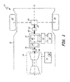
- FIG. 1 is a block diagram illustrating a propulsion system according to an embodiment of the present invention.
- FIG. 2 is a schematic diagram illustrating a flywheel energy storage (FES) device according to an embodiment of the present invention.
- FES flywheel energy storage
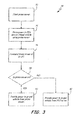
- FIG. 3 is a flowchart illustrating a method of propelling a vehicle according to an embodiment of the present invention.
- the present invention is a propulsion system primarily intended for advanced military unmanned ground vehicles (UGVs), but also applicable to a wide range of other drive systems.
- This invention provides primary power with a conventional prime mover such as a gas turbine, a microturbine, or an internal combustion engine.
- the prime mover transmits torque to a flywheel energy storage (FES) device via a one-way or two-way torque transmission shaft.
- FES device comprises a flywheel and a brushless machine on a shared axis driven by the torque transmission shaft.
- the brushless machine (operating as a generator) allows flywheel kinetic energy to be converted into electrical energy. Electrical energy can also be discharged through the brushless machine (operating as a motor) to drive the flywheel.
- the shared axis of the FES connects to a propulsion driveshaft, such as a driveshaft for wheels of a ground vehicle.
- stored energy in the FES device can be used to propel the vehicle when the prime mover is commanded off.
- FIG. 1 is a block diagram illustrating a propulsion system 10 according to an embodiment of the present invention.
- System 10 includes vehicle 12, prime mover 14, torque transmission shaft 16, flywheel energy storage (FES) device 18, FES output shaft 20, step-down gear 22, wheels 24, transaxle/gearbox 26, driveshaft 28, battery charger 30, battery 32, controller 34, vehicle input/output (I/O) 36, electromagnetic clutch 38, flywheel 40, and permanent magnet (PM) brushless machine 42.
- vehicle 12 may be any vehicle that is propelled by a prime mover such as, for example, an aircraft or a submarine.
- Prime mover 14 may be implemented as, for example, a gas turbine, a microturbine, an internal combustion engine, or any other prime mover known in the art.
- Battery 32 may be a conventional chemical battery, a supercapacitor, or any other functional equivalent.
- Battery charger 30 may be implemented as a solid state battery charger.
- Prime mover 14 is commanded on and off using controller 34 which may be implemented, for example, as a microcontroller.
- controller 34 includes vehicle input/output 36.
- Vehicle input/output 36 is implemented using any sufficient wireless communication known in the art, such as a wireless transponder. This allows remote control of vehicle 12.
- Controller 34 contains digital logic to receive external commands and operate the vehicle accordingly, as well as transmit data regarding current operating conditions.
- controller 34 may be implemented with digital logic to autonomously control propulsion of vehicle 12. Controller 34 may also be implemented to control aspects of the vehicle such as the direction of travel, speed and other common travel variables.
- FES device 18 When commanding prime mover 14 on, FES device 18 may be used to initiate startup.
- FES device 18 includes flywheel 40 for storing kinetic energy, and PM brushless machine 42.
- PM brushless machine 42 can operate as a generator or a motor.
- battery 32 provides electrical energy through battery charger 30 to drive FES device 18.
- PM brushless machine 42 of FES device 18 is used to convert the electrical energy from battery 32 into kinetic energy to turn flywheel 40 of FES device 18.
- torque transmission shaft 16 is a typical rigid two-way shaft.
- torque transmission shaft 16 may be a one-way torque transmission shaft (such as a shaft-within-a-shaft construction) which transmits torque only from prime mover 14 to FES device 18, and not vice versa. If utilizing a one-way shaft, FES device 18 cannot be used to start prime mover 14.
- prime mover 14 When prime mover 14 is commanded off by controller 34, power is provided to propel vehicle 12 from FES device 18. During this time, kinetic energy stored in flywheel 40 turns FES output shaft 20. This energy goes through FES output shaft 20 to step-down gear 22, and then to transaxle/gearbox 26, driveshaft 28, and wheels 24 in order to propel vehicle 12. Battery 32 may be used to provide further energy while prime mover 14 is commanded off. In this case, battery 32 provides electrical energy through battery charger 30 to PM brushless machine 42. PM brushless machine 42 acts as a motor to provide further energy to turn FES output shaft 20. While FES device 18 is providing power and prime mover 14 is commanded off, vehicle 12 creates very little noise, which is ideal for advanced military applications.
- FES device 18 can be used to propel vehicle 12 for a period of time, for example, of 4-6 minutes. This is ideal for short time duty operations such as vehicle maneuvering, stealth operations, and supplying power to communications systems, targeting systems, and navigation systems.
- controller 34 may also operate electromagnetic clutch 38 in order to decouple prime mover 14 from FES device 18. This removes friction, allowing for more efficient use of the energy stored in FES device 18.
- FIG. 2 is a schematic diagram illustrating FES device 18 according to an embodiment of the present invention.
- FES device 18 includes flywheel 40, rotor 44, stator 46, radial magnetic bearings 48, backup bearings 50, thrust magnetic bearing 52, burst shield 54, vacuum containment 56 and vacuum chamber 58.
- Flywheel 40 spins in vacuum chamber 58 in order to reduce air friction and extend energy storage time.
- the use of magnetic bearings 48 and thrust magnetic bearing 52 reduces bearing energy loss, which maximizes the efficiency and energy stored in FES device 18.
- Rotor 44 and stator 46 comprise PM brushless machine 42. This PM brushless machine acts as a motor/generator.
- PM brushless machine 42 acts as a generator to convert kinetic energy from flywheel 40 into electric energy.
- PM brushless machine 42 can act as a motor, receiving electric energy from battery 32 and converting it into kinetic energy to spin flywheel 40.
- FIG. 3 is a flowchart illustrating a method 70 of providing power to propel a vehicle according to an embodiment of the present invention.
- prime mover 14 is started using FES device 18.
- FES device 18 stores power from prime mover 14 and prime mover 14 provides power to propel vehicle 12 through FES device 18.
- controller 34 commands prime mover 14 on or off.
- prime mover 14 provides power to propel vehicle 12 through FES device 18.
- FES device 18 provides stored power to propel vehicle 12.
- Electromagnetic clutch 38 is operated to decouple prime mover 14 from FES device 18..
- the present invention describes a system and method for propelling a vehicle utilizing a flywheel energy storage device.
Landscapes
- Engineering & Computer Science (AREA)
- Chemical & Material Sciences (AREA)
- Combustion & Propulsion (AREA)
- Transportation (AREA)
- Mechanical Engineering (AREA)
- Automation & Control Theory (AREA)
- Electric Propulsion And Braking For Vehicles (AREA)
Abstract
A propulsion system (10) includes a prime mover (14) for providing primary power to propel a vehicle (12); a flywheel energy storage device(18) for providing secondary power to propel the vehicle(12) when primary power is not being provided, wherein the flywheel energy storage device (18) stores power provided by the prime mover (14); and a controller (34) for commanding the prime mover (14) on and off.
Description
- The present invention is related to propulsion systems, and in particular to a system and method for providing propulsion to a vehicle using a flywheel energy storage (FES) device.
- Vehicles such as advanced military land vehicles require long-range autonomous power supplies to complete their missions in adverse ambient conditions and difficult terrains. With the changing military doctrine of terrorism, suburban warfare, and covert mission reconnaissance, the advanced unmanned ground vehicle (UGV) has come to require fully-integrated thermal power and communications. It is expected that such small UGVs can be employed in a variety of roles, such as minesweeping, explosives and chemical/biological agents detection, missile guidance, and active reconnaissance.
- Unlike typical land vehicles where power is delivered to the power train continuously over long periods of time, advanced military UGVs typically operate in a "stop-and-go" pattern either probing the ground carefully for hidden mines, or checking the underbodies of parked vehicles in a busy city street for hidden items such as explosives, drugs, and chemical/biological agents. Therefore, it is desirable to provide a prime mover device that not only provides long autonomous operation, but also delivers high bursts of concentrated energy to provide torque to move the UGVs in this typical "stop-and-go" pattern.
- A propulsion system includes a prime mover for providing primary power to propel a vehicle, a flywheel energy storage device for providing secondary power to propel the vehicle when primary power is not being provided, and a controller for commanding the prime mover on and off. The flywheel energy storage device stores power provided by the prime mover.
-
FIG. 1 is a block diagram illustrating a propulsion system according to an embodiment of the present invention. -
FIG. 2 is a schematic diagram illustrating a flywheel energy storage (FES) device according to an embodiment of the present invention. -
FIG. 3 is a flowchart illustrating a method of propelling a vehicle according to an embodiment of the present invention. - The present invention is a propulsion system primarily intended for advanced military unmanned ground vehicles (UGVs), but also applicable to a wide range of other drive systems. This invention provides primary power with a conventional prime mover such as a gas turbine, a microturbine, or an internal combustion engine. The prime mover transmits torque to a flywheel energy storage (FES) device via a one-way or two-way torque transmission shaft. The FES device comprises a flywheel and a brushless machine on a shared axis driven by the torque transmission shaft. The brushless machine (operating as a generator) allows flywheel kinetic energy to be converted into electrical energy. Electrical energy can also be discharged through the brushless machine (operating as a motor) to drive the flywheel. The shared axis of the FES connects to a propulsion driveshaft, such as a driveshaft for wheels of a ground vehicle. Thus, stored energy in the FES device can be used to propel the vehicle when the prime mover is commanded off.
-
FIG. 1 is a block diagram illustrating apropulsion system 10 according to an embodiment of the present invention.System 10 includesvehicle 12,prime mover 14,torque transmission shaft 16, flywheel energy storage (FES)device 18,FES output shaft 20, step-down gear 22,wheels 24, transaxle/gearbox 26,driveshaft 28,battery charger 30,battery 32,controller 34, vehicle input/output (I/O) 36,electromagnetic clutch 38,flywheel 40, and permanent magnet (PM)brushless machine 42. Although illustrated as a ground vehicle,vehicle 12 may be any vehicle that is propelled by a prime mover such as, for example, an aircraft or a submarine.Prime mover 14 may be implemented as, for example, a gas turbine, a microturbine, an internal combustion engine, or any other prime mover known in the art.Battery 32 may be a conventional chemical battery, a supercapacitor, or any other functional equivalent.Battery charger 30 may be implemented as a solid state battery charger. - Prime
mover 14 is commanded on and off usingcontroller 34 which may be implemented, for example, as a microcontroller. In the present embodiment,controller 34 includes vehicle input/output 36. Vehicle input/output 36 is implemented using any sufficient wireless communication known in the art, such as a wireless transponder. This allows remote control ofvehicle 12.Controller 34 contains digital logic to receive external commands and operate the vehicle accordingly, as well as transmit data regarding current operating conditions. In a separate embodiment,controller 34 may be implemented with digital logic to autonomously control propulsion ofvehicle 12.Controller 34 may also be implemented to control aspects of the vehicle such as the direction of travel, speed and other common travel variables. - When commanding
prime mover 14 on, FESdevice 18 may be used to initiate startup.FES device 18 includesflywheel 40 for storing kinetic energy, and PMbrushless machine 42. PMbrushless machine 42 can operate as a generator or a motor. During startup ofprime mover 14,battery 32 provides electrical energy throughbattery charger 30 to driveFES device 18. PMbrushless machine 42 ofFES device 18 is used to convert the electrical energy frombattery 32 into kinetic energy to turnflywheel 40 ofFES device 18. OnceFES device 18 is turning, torque is transmitted to prime mover 14 throughtorque transmission shaft 16. In the present embodiment,torque transmission shaft 16 is a typical rigid two-way shaft. In another embodiment,torque transmission shaft 16 may be a one-way torque transmission shaft (such as a shaft-within-a-shaft construction) which transmits torque only fromprime mover 14 toFES device 18, and not vice versa. If utilizing a one-way shaft,FES device 18 cannot be used to startprime mover 14. - During primary power operation in which
prime mover 14 is providing power to propelvehicle 12, torque fromtorque transmission shaft 16 energizesFES device 18. This spinsflywheel 14 up to a high revolutions per minute (RPM), such as 30,000-50,000 RPM. The greater part of the mechanical energy supplied byprime mover 14 goes throughFES device 18 to step-downgear 22, and then to transaxle/gearbox 26,driveshaft 28, andwheels 24 in order to propelvehicle 12. Transaxle/gearbox 26,driveshaft 28, andUGV wheels 24 may be replaced with other drive components for applications other than ground vehicle propulsion. Whenprime mover 14 is transmitting torque toFES device 18, PMbrushless machine 42 acts as a generator to chargebattery 32 throughbattery charger 30. Electricity from PMbrushless machine 42 may also be used to power other electronics withinvehicle 12. This provides redundancy for electric energy availability between PMbrushless machine 42 andbattery 32. - When
prime mover 14 is commanded off bycontroller 34, power is provided to propelvehicle 12 fromFES device 18. During this time, kinetic energy stored inflywheel 40 turnsFES output shaft 20. This energy goes throughFES output shaft 20 to step-downgear 22, and then to transaxle/gearbox 26, driveshaft 28, andwheels 24 in order to propelvehicle 12.Battery 32 may be used to provide further energy whileprime mover 14 is commanded off. In this case,battery 32 provides electrical energy throughbattery charger 30 to PMbrushless machine 42. PMbrushless machine 42 acts as a motor to provide further energy to turnFES output shaft 20. While FESdevice 18 is providing power andprime mover 14 is commanded off,vehicle 12 creates very little noise, which is ideal for advanced military applications. -
FES device 18 can be used to propelvehicle 12 for a period of time, for example, of 4-6 minutes. This is ideal for short time duty operations such as vehicle maneuvering, stealth operations, and supplying power to communications systems, targeting systems, and navigation systems. During this time,controller 34 may also operateelectromagnetic clutch 38 in order to decoupleprime mover 14 fromFES device 18. This removes friction, allowing for more efficient use of the energy stored inFES device 18. -
FIG. 2 is a schematic diagram illustratingFES device 18 according to an embodiment of the present invention.FES device 18 includesflywheel 40,rotor 44,stator 46, radialmagnetic bearings 48,backup bearings 50, thrustmagnetic bearing 52,burst shield 54,vacuum containment 56 andvacuum chamber 58.Flywheel 40 spins invacuum chamber 58 in order to reduce air friction and extend energy storage time. Similarly, the use ofmagnetic bearings 48 and thrustmagnetic bearing 52 reduces bearing energy loss, which maximizes the efficiency and energy stored inFES device 18.Rotor 44 andstator 46 comprisePM brushless machine 42. This PM brushless machine acts as a motor/generator. During primary operation (whenprime mover 14 is providing power to propel vehicle 12),PM brushless machine 42 acts as a generator to convert kinetic energy fromflywheel 40 into electric energy. Whenprime mover 14 is not providing power to propelvehicle 12,PM brushless machine 42 can act as a motor, receiving electric energy frombattery 32 and converting it into kinetic energy to spinflywheel 40. -
FIG. 3 is a flowchart illustrating amethod 70 of providing power to propel a vehicle according to an embodiment of the present invention. Atstep 72,prime mover 14 is started usingFES device 18. Atstep 74,FES device 18 stores power fromprime mover 14 andprime mover 14 provides power to propelvehicle 12 throughFES device 18. Atstep 76,controller 34 commandsprime mover 14 on or off. Atstep 78, it is determined if power is being provided to propelvehicle 12 fromprime mover 14 or fromFES device 18. Ifprime mover 14 is providing power to propelvehicle 12,method 70 proceeds to step 80. Ifprime mover 14 is off, andFES device 18 is providing power to propelvehicle 12,method 70 proceeds to step 82. Atstep 80,prime mover 14 provides power to propelvehicle 12 throughFES device 18. Atstep 82,FES device 18 provides stored power to propelvehicle 12. Electromagnetic clutch 38 is operated to decoupleprime mover 14 fromFES device 18.. - In this way, the present invention describes a system and method for propelling a vehicle utilizing a flywheel energy storage device. Although the present invention has been described with reference to preferred embodiments, workers skilled in the art will recognize that changes may be made in form and detail without departing from the spirit and scope of the invention.
Claims (15)
- A propulsion system (10) comprising:a prime mover (14) for providing primary power to propel a vehicle (12);a flywheel energy storage device (18) for providing secondary power to propel the
vehicle (14) when primary power is not being provided, wherein the flywheel energy storage (18) device stores power provided by the prime mover (14); anda controller (34) for commanding the prime mover (14) on and off. - The system of claim 1, further comprising:a battery (32) for providing power to the flywheel energy storage device (18) when the
flywheel energy storage device (18) is not receiving energy from the prime mover (14); anda battery charger (30) for charging the battery (32) when the flywheel energy storage
device (18) is receiving energy from the prime mover (14). - The system of claim 2, wherein the battery (32) provides energy to the flywheel energy storage device (18) in order to start up the prime mover (14).
- The system of claim 1, wherein the vehicle (12) is an unmanned ground vehicle.
- The system of claim 1, wherein the controller (34) is controlled externally through an input/output (I/O) interface.
- A method for propelling a vehicle (12), the method comprising:providing power to propel the vehicle (12) using a prime mover (14);storing energy from the prime mover (14) using a flywheel energy storage (FES) device (18); andproviding stored power to propel the vehicle using the FES device (18) when power from
the prime mover (14) is unavailable. - The method of claim 6, further comprising providing power to the FES device (18) using a battery (32) in order to startup the prime mover (14) prior to providing power to propel the vehicle (12) using the prime mover (14).
- The method of claim 6, further comprising controlling the prime mover (14) on and off using a controller (34), wherein when the prime mover (14) is on, power is provided to propel the vehicle (12) using the prime mover (14) and when the prime mover (14) is off, stored power is provided to propel the vehicle (12) using the FES device (18).
- The system of claim 1 or the method of claim 6, wherein the prime mover (14) is a gas turbine engine.
- The method of claim 6, wherein providing stored power to propel the vehicle (12) using the FES device (18) further comprises providing electric power to the FES device using a battery (32).
- The method of claim 10, wherein storing energy from the prime mover (14) includes the FES device (18) providing power to charge the battery (32).
- The system of claim 1 or the method of claim 6, wherein the FES device comprises:a flywheel (40); anda permanent magnet (PM) brushless machine (42) for converting mechanical energy from
the flywheel (40) into electrical energy. - The system or method of claim 12, wherein the flywheel (40) is enclosed in a vacuum, and/or wherein the PM brushless machine (42) includes magnetic bearings.
- The method of claim 6, wherein providing power to propel the vehicle (12) using the prime mover (14) comprises providing power from the prime mover (14) through the FES device (18).
- The method of claim 6, wherein providing stored power to propel the vehicle (12) comprises decoupling the FES device (18) from the prime mover (14) using an electromagnetic clutch.
Applications Claiming Priority (1)
| Application Number | Priority Date | Filing Date | Title |
|---|---|---|---|
| US13/488,624 US20130325287A1 (en) | 2012-06-05 | 2012-06-05 | Flywheel energy storage for vehicle propulsion |
Publications (1)
| Publication Number | Publication Date |
|---|---|
| EP2671744A1 true EP2671744A1 (en) | 2013-12-11 |
Family
ID=48569944
Family Applications (1)
| Application Number | Title | Priority Date | Filing Date |
|---|---|---|---|
| EP13169502.5A Withdrawn EP2671744A1 (en) | 2012-06-05 | 2013-05-28 | Flywheel energy storage for vehicle propulsion |
Country Status (2)
| Country | Link |
|---|---|
| US (1) | US20130325287A1 (en) |
| EP (1) | EP2671744A1 (en) |
Families Citing this family (5)
| Publication number | Priority date | Publication date | Assignee | Title |
|---|---|---|---|---|
| EP2710272B1 (en) * | 2011-05-17 | 2019-01-23 | Dresser-Rand Company | Coast down bushing for magnetic bearing systems |
| WO2015130563A1 (en) * | 2014-02-28 | 2015-09-03 | United Technologies Corporation | Protected wireless network |
| EP3240725A1 (en) * | 2014-12-31 | 2017-11-08 | MRA Systems, Inc. | Aircraft using energy recovery systems |
| CN108608871A (en) * | 2018-03-19 | 2018-10-02 | 江苏大学 | A kind of automobile-used composite energy storing device and its working method based on lithium battery, super capacitor and flying wheel battery |
| US11873765B1 (en) * | 2023-01-10 | 2024-01-16 | Rolls-Royce North American Technologies Inc. | Flywheel powered barring engine for gas turbine engine |
Citations (7)
| Publication number | Priority date | Publication date | Assignee | Title |
|---|---|---|---|---|
| US3771311A (en) * | 1971-02-01 | 1973-11-13 | Exxon Research Engineering Co | Power system |
| DE2332514A1 (en) * | 1973-06-22 | 1975-01-16 | Joachim Dr Ing Wernicke | Vehicle fuel saving brake transmission - has fly wheel connected by variable ratio transmission to absorb braking kinetic energy |
| US4309620A (en) * | 1979-12-03 | 1982-01-05 | Calspan Corporation | Flywheel electric transmission apparatus |
| US5931249A (en) * | 1993-09-08 | 1999-08-03 | Ellis; Christopher William Henderson | Kinetic energy storage system |
| US20060207811A1 (en) * | 2005-03-16 | 2006-09-21 | Takayuki Miyao | Method of controlling vehicle driving system |
| GB2448598A (en) * | 2007-04-16 | 2008-10-22 | Ricardo Uk Ltd | Magnetic coupling to flywheel |
| US20110036650A1 (en) * | 2007-11-07 | 2011-02-17 | Gs Engineering, Inc. | Multi-purpose ground vehicle |
-
2012
- 2012-06-05 US US13/488,624 patent/US20130325287A1/en not_active Abandoned
-
2013
- 2013-05-28 EP EP13169502.5A patent/EP2671744A1/en not_active Withdrawn
Patent Citations (7)
| Publication number | Priority date | Publication date | Assignee | Title |
|---|---|---|---|---|
| US3771311A (en) * | 1971-02-01 | 1973-11-13 | Exxon Research Engineering Co | Power system |
| DE2332514A1 (en) * | 1973-06-22 | 1975-01-16 | Joachim Dr Ing Wernicke | Vehicle fuel saving brake transmission - has fly wheel connected by variable ratio transmission to absorb braking kinetic energy |
| US4309620A (en) * | 1979-12-03 | 1982-01-05 | Calspan Corporation | Flywheel electric transmission apparatus |
| US5931249A (en) * | 1993-09-08 | 1999-08-03 | Ellis; Christopher William Henderson | Kinetic energy storage system |
| US20060207811A1 (en) * | 2005-03-16 | 2006-09-21 | Takayuki Miyao | Method of controlling vehicle driving system |
| GB2448598A (en) * | 2007-04-16 | 2008-10-22 | Ricardo Uk Ltd | Magnetic coupling to flywheel |
| US20110036650A1 (en) * | 2007-11-07 | 2011-02-17 | Gs Engineering, Inc. | Multi-purpose ground vehicle |
Also Published As
| Publication number | Publication date |
|---|---|
| US20130325287A1 (en) | 2013-12-05 |
Similar Documents
| Publication | Publication Date | Title |
|---|---|---|
| US10371066B2 (en) | Unmanned aircraft and operation method for the same | |
| US9771162B1 (en) | On-board redundant power system for unmanned aerial vehicles | |
| US10017266B2 (en) | Power generation and distribution for vehicle propulsion | |
| US20130325287A1 (en) | Flywheel energy storage for vehicle propulsion | |
| EP2962885B1 (en) | Hybrid power system for piston engine aircrafts | |
| EP3002435B1 (en) | Accessory drive system for a gas turbine engine | |
| EP3032075B1 (en) | Integrated apu generator constant speed drive | |
| CN101746507A (en) | Hybrid power for ducted fan unmanned aerial systems | |
| EP3418674B1 (en) | Pulsed power hybrid electric unmanned underwater vehicle propulsion system | |
| US20200039657A1 (en) | Variable Cycle Hybrid Power and Propulsion System for Aircraft | |
| US11009327B2 (en) | Series hybrid architecture for an unmanned underwater vehicle propulsion system | |
| EP3643901B1 (en) | Hybrid starter motor-generator | |
| McFarland et al. | A long-range naval railgun | |
| EP3418671A1 (en) | Unmanned underwater vehicle propulsion system including a dc bus | |
| IL289683A (en) | Unmanned aerial vehicle drive assembly | |
| JP2019506327A (en) | Power generation and distribution for vehicle propulsion | |
| US20210347258A1 (en) | System and method for a differential disconnect electric axle | |
| US20180079291A1 (en) | Power generation and distribution for land-based vehicle propulsion | |
| EP2184230A2 (en) | Soldier portable generator | |
| WO2022187032A2 (en) | Flexible architecture for an aerospace hybrid system and optimized components thereof | |
| CN110775301A (en) | Aircraft with high rail-entering efficiency and strong maneuvering capability and rail-entering method thereof | |
| UA94802U (en) | POWERFUL INSTALLATION OF A UAV | |
| US20110291602A1 (en) | Electromagnetic Pulse Engine | |
| TR202022757A2 (en) | INTELLIGENT MODULAR HYBRID DRIVE SYSTEM AND ITS MANAGEMENT METHOD | |
| Minami et al. | Radio-controlled Electric Vehicles Issues Relating to the Safety of Unmanned Electric Vehicles and Robots |
Legal Events
| Date | Code | Title | Description |
|---|---|---|---|
| PUAI | Public reference made under article 153(3) epc to a published international application that has entered the european phase |
Free format text: ORIGINAL CODE: 0009012 |
|
| AK | Designated contracting states |
Kind code of ref document: A1 Designated state(s): AL AT BE BG CH CY CZ DE DK EE ES FI FR GB GR HR HU IE IS IT LI LT LU LV MC MK MT NL NO PL PT RO RS SE SI SK SM TR |
|
| AX | Request for extension of the european patent |
Extension state: BA ME |
|
| STAA | Information on the status of an ep patent application or granted ep patent |
Free format text: STATUS: THE APPLICATION IS DEEMED TO BE WITHDRAWN |
|
| 18D | Application deemed to be withdrawn |
Effective date: 20140612 |