EP2671635A1 - Temperature control system - Google Patents
Temperature control system Download PDFInfo
- Publication number
- EP2671635A1 EP2671635A1 EP12742759.9A EP12742759A EP2671635A1 EP 2671635 A1 EP2671635 A1 EP 2671635A1 EP 12742759 A EP12742759 A EP 12742759A EP 2671635 A1 EP2671635 A1 EP 2671635A1
- Authority
- EP
- European Patent Office
- Prior art keywords
- coolant
- temperature
- reactor
- drum
- unit
- Prior art date
- Legal status (The legal status is an assumption and is not a legal conclusion. Google has not performed a legal analysis and makes no representation as to the accuracy of the status listed.)
- Withdrawn
Links
Images


Classifications
-
- F—MECHANICAL ENGINEERING; LIGHTING; HEATING; WEAPONS; BLASTING
- F28—HEAT EXCHANGE IN GENERAL
- F28F—DETAILS OF HEAT-EXCHANGE AND HEAT-TRANSFER APPARATUS, OF GENERAL APPLICATION
- F28F27/00—Control arrangements or safety devices specially adapted for heat-exchange or heat-transfer apparatus
-
- B—PERFORMING OPERATIONS; TRANSPORTING
- B01—PHYSICAL OR CHEMICAL PROCESSES OR APPARATUS IN GENERAL
- B01J—CHEMICAL OR PHYSICAL PROCESSES, e.g. CATALYSIS OR COLLOID CHEMISTRY; THEIR RELEVANT APPARATUS
- B01J19/00—Chemical, physical or physico-chemical processes in general; Their relevant apparatus
- B01J19/0006—Controlling or regulating processes
- B01J19/0013—Controlling the temperature of the process
-
- B—PERFORMING OPERATIONS; TRANSPORTING
- B01—PHYSICAL OR CHEMICAL PROCESSES OR APPARATUS IN GENERAL
- B01J—CHEMICAL OR PHYSICAL PROCESSES, e.g. CATALYSIS OR COLLOID CHEMISTRY; THEIR RELEVANT APPARATUS
- B01J8/00—Chemical or physical processes in general, conducted in the presence of fluids and solid particles; Apparatus for such processes
- B01J8/001—Controlling catalytic processes
-
- C—CHEMISTRY; METALLURGY
- C10—PETROLEUM, GAS OR COKE INDUSTRIES; TECHNICAL GASES CONTAINING CARBON MONOXIDE; FUELS; LUBRICANTS; PEAT
- C10G—CRACKING HYDROCARBON OILS; PRODUCTION OF LIQUID HYDROCARBON MIXTURES, e.g. BY DESTRUCTIVE HYDROGENATION, OLIGOMERISATION, POLYMERISATION; RECOVERY OF HYDROCARBON OILS FROM OIL-SHALE, OIL-SAND, OR GASES; REFINING MIXTURES MAINLY CONSISTING OF HYDROCARBONS; REFORMING OF NAPHTHA; MINERAL WAXES
- C10G2/00—Production of liquid hydrocarbon mixtures of undefined composition from oxides of carbon
- C10G2/30—Production of liquid hydrocarbon mixtures of undefined composition from oxides of carbon from carbon monoxide with hydrogen
-
- C—CHEMISTRY; METALLURGY
- C10—PETROLEUM, GAS OR COKE INDUSTRIES; TECHNICAL GASES CONTAINING CARBON MONOXIDE; FUELS; LUBRICANTS; PEAT
- C10G—CRACKING HYDROCARBON OILS; PRODUCTION OF LIQUID HYDROCARBON MIXTURES, e.g. BY DESTRUCTIVE HYDROGENATION, OLIGOMERISATION, POLYMERISATION; RECOVERY OF HYDROCARBON OILS FROM OIL-SHALE, OIL-SAND, OR GASES; REFINING MIXTURES MAINLY CONSISTING OF HYDROCARBONS; REFORMING OF NAPHTHA; MINERAL WAXES
- C10G2/00—Production of liquid hydrocarbon mixtures of undefined composition from oxides of carbon
- C10G2/30—Production of liquid hydrocarbon mixtures of undefined composition from oxides of carbon from carbon monoxide with hydrogen
- C10G2/32—Production of liquid hydrocarbon mixtures of undefined composition from oxides of carbon from carbon monoxide with hydrogen with the use of catalysts
- C10G2/34—Apparatus, reactors
-
- B—PERFORMING OPERATIONS; TRANSPORTING
- B01—PHYSICAL OR CHEMICAL PROCESSES OR APPARATUS IN GENERAL
- B01J—CHEMICAL OR PHYSICAL PROCESSES, e.g. CATALYSIS OR COLLOID CHEMISTRY; THEIR RELEVANT APPARATUS
- B01J2219/00—Chemical, physical or physico-chemical processes in general; Their relevant apparatus
- B01J2219/00049—Controlling or regulating processes
- B01J2219/00051—Controlling the temperature
- B01J2219/00054—Controlling or regulating the heat exchange system
- B01J2219/00056—Controlling or regulating the heat exchange system involving measured parameters
- B01J2219/00058—Temperature measurement
- B01J2219/00063—Temperature measurement of the reactants
-
- B—PERFORMING OPERATIONS; TRANSPORTING
- B01—PHYSICAL OR CHEMICAL PROCESSES OR APPARATUS IN GENERAL
- B01J—CHEMICAL OR PHYSICAL PROCESSES, e.g. CATALYSIS OR COLLOID CHEMISTRY; THEIR RELEVANT APPARATUS
- B01J2219/00—Chemical, physical or physico-chemical processes in general; Their relevant apparatus
- B01J2219/00049—Controlling or regulating processes
- B01J2219/00051—Controlling the temperature
- B01J2219/00054—Controlling or regulating the heat exchange system
- B01J2219/00056—Controlling or regulating the heat exchange system involving measured parameters
- B01J2219/00065—Pressure measurement
-
- B—PERFORMING OPERATIONS; TRANSPORTING
- B01—PHYSICAL OR CHEMICAL PROCESSES OR APPARATUS IN GENERAL
- B01J—CHEMICAL OR PHYSICAL PROCESSES, e.g. CATALYSIS OR COLLOID CHEMISTRY; THEIR RELEVANT APPARATUS
- B01J2219/00—Chemical, physical or physico-chemical processes in general; Their relevant apparatus
- B01J2219/00049—Controlling or regulating processes
- B01J2219/00051—Controlling the temperature
- B01J2219/00054—Controlling or regulating the heat exchange system
- B01J2219/00056—Controlling or regulating the heat exchange system involving measured parameters
- B01J2219/00067—Liquid level measurement
-
- B—PERFORMING OPERATIONS; TRANSPORTING
- B01—PHYSICAL OR CHEMICAL PROCESSES OR APPARATUS IN GENERAL
- B01J—CHEMICAL OR PHYSICAL PROCESSES, e.g. CATALYSIS OR COLLOID CHEMISTRY; THEIR RELEVANT APPARATUS
- B01J2219/00—Chemical, physical or physico-chemical processes in general; Their relevant apparatus
- B01J2219/00049—Controlling or regulating processes
- B01J2219/00051—Controlling the temperature
- B01J2219/00074—Controlling the temperature by indirect heating or cooling employing heat exchange fluids
- B01J2219/00076—Controlling the temperature by indirect heating or cooling employing heat exchange fluids with heat exchange elements inside the reactor
- B01J2219/00081—Tubes
-
- B—PERFORMING OPERATIONS; TRANSPORTING
- B01—PHYSICAL OR CHEMICAL PROCESSES OR APPARATUS IN GENERAL
- B01J—CHEMICAL OR PHYSICAL PROCESSES, e.g. CATALYSIS OR COLLOID CHEMISTRY; THEIR RELEVANT APPARATUS
- B01J2219/00—Chemical, physical or physico-chemical processes in general; Their relevant apparatus
- B01J2219/00049—Controlling or regulating processes
- B01J2219/00162—Controlling or regulating processes controlling the pressure
-
- B—PERFORMING OPERATIONS; TRANSPORTING
- B01—PHYSICAL OR CHEMICAL PROCESSES OR APPARATUS IN GENERAL
- B01J—CHEMICAL OR PHYSICAL PROCESSES, e.g. CATALYSIS OR COLLOID CHEMISTRY; THEIR RELEVANT APPARATUS
- B01J2219/00—Chemical, physical or physico-chemical processes in general; Their relevant apparatus
- B01J2219/00049—Controlling or regulating processes
- B01J2219/00191—Control algorithm
- B01J2219/00193—Sensing a parameter
- B01J2219/00195—Sensing a parameter of the reaction system
- B01J2219/002—Sensing a parameter of the reaction system inside the reactor
-
- B—PERFORMING OPERATIONS; TRANSPORTING
- B01—PHYSICAL OR CHEMICAL PROCESSES OR APPARATUS IN GENERAL
- B01J—CHEMICAL OR PHYSICAL PROCESSES, e.g. CATALYSIS OR COLLOID CHEMISTRY; THEIR RELEVANT APPARATUS
- B01J2219/00—Chemical, physical or physico-chemical processes in general; Their relevant apparatus
- B01J2219/00049—Controlling or regulating processes
- B01J2219/00191—Control algorithm
- B01J2219/00211—Control algorithm comparing a sensed parameter with a pre-set value
- B01J2219/00213—Fixed parameter value
-
- B—PERFORMING OPERATIONS; TRANSPORTING
- B01—PHYSICAL OR CHEMICAL PROCESSES OR APPARATUS IN GENERAL
- B01J—CHEMICAL OR PHYSICAL PROCESSES, e.g. CATALYSIS OR COLLOID CHEMISTRY; THEIR RELEVANT APPARATUS
- B01J2219/00—Chemical, physical or physico-chemical processes in general; Their relevant apparatus
- B01J2219/00049—Controlling or regulating processes
- B01J2219/00191—Control algorithm
- B01J2219/00222—Control algorithm taking actions
- B01J2219/00227—Control algorithm taking actions modifying the operating conditions
- B01J2219/00238—Control algorithm taking actions modifying the operating conditions of the heat exchange system
-
- F—MECHANICAL ENGINEERING; LIGHTING; HEATING; WEAPONS; BLASTING
- F28—HEAT EXCHANGE IN GENERAL
- F28D—HEAT-EXCHANGE APPARATUS, NOT PROVIDED FOR IN ANOTHER SUBCLASS, IN WHICH THE HEAT-EXCHANGE MEDIA DO NOT COME INTO DIRECT CONTACT
- F28D21/00—Heat-exchange apparatus not covered by any of the groups F28D1/00 - F28D20/00
- F28D2021/0019—Other heat exchangers for particular applications; Heat exchange systems not otherwise provided for
- F28D2021/0033—Other heat exchangers for particular applications; Heat exchange systems not otherwise provided for for cryogenic applications
-
- F—MECHANICAL ENGINEERING; LIGHTING; HEATING; WEAPONS; BLASTING
- F28—HEAT EXCHANGE IN GENERAL
- F28D—HEAT-EXCHANGE APPARATUS, NOT PROVIDED FOR IN ANOTHER SUBCLASS, IN WHICH THE HEAT-EXCHANGE MEDIA DO NOT COME INTO DIRECT CONTACT
- F28D21/00—Heat-exchange apparatus not covered by any of the groups F28D1/00 - F28D20/00
- F28D2021/0019—Other heat exchangers for particular applications; Heat exchange systems not otherwise provided for
- F28D2021/0061—Other heat exchangers for particular applications; Heat exchange systems not otherwise provided for for phase-change applications
- F28D2021/0064—Vaporizers, e.g. evaporators
-
- F—MECHANICAL ENGINEERING; LIGHTING; HEATING; WEAPONS; BLASTING
- F28—HEAT EXCHANGE IN GENERAL
- F28D—HEAT-EXCHANGE APPARATUS, NOT PROVIDED FOR IN ANOTHER SUBCLASS, IN WHICH THE HEAT-EXCHANGE MEDIA DO NOT COME INTO DIRECT CONTACT
- F28D21/00—Heat-exchange apparatus not covered by any of the groups F28D1/00 - F28D20/00
- F28D2021/0019—Other heat exchangers for particular applications; Heat exchange systems not otherwise provided for
- F28D2021/0077—Other heat exchangers for particular applications; Heat exchange systems not otherwise provided for for tempering, e.g. with cooling or heating circuits for temperature control of elements
Definitions
- the present invention relates to a temperature control system.
- Priority is claimed on Japanese Patent Application No. 2011-18263, filed on January 31, 2011 , the content of which is incorporated herein by reference.
- This GLT technique includes the steps of reforming a natural gas to produce a synthesis gas containing a carbon monoxide gas (CO) and a hydrogen gas (H 2 ) as main components, synthesizing liquid hydrocarbons using this synthesis gas as a feedstock via the Fischer-Tropsch synthesis reaction (hereinafter, also referred to as the FT synthesis reaction) and then hydrogenating and fractionating these liquid hydrocarbons to produce liquid fuel products such as naphtha (raw gasoline), kerosene, gas oil, wax and the like.
- a reactor which carries out an exothermic reaction can convert the synthesis gas rich in hydrogen gas and carbon monoxide gas to hydrocarbons by using a catalyst.
- the FT synthesis reaction is an exothermic reaction and also quite narrow in its temperature range where the reaction proceeds appropriately, by which it is necessary to strictly control a reaction temperature inside the reactor, while recovering reaction heat which has been generated.
- a heat recovery system for recovering reaction heat inside a reactor there is known, for example, a constitution described in Patent Document 1 given below.
- a jacket-equipped conduit is disposed inside the reactor, and water which is supplied to an external boiler is circulated to a jacket space inside the jacket-equipped conduit, thereby recovering the reaction heat inside the reactor.
- the present invention has been developed in light of the above circumstances, and has an object of providing a temperature control system which is capable of quickly dealing with a change in temperature inside a reactor and controlling the temperature inside the reactor with high accuracy.
- the temperature control system of the present invention is a temperature control system for recovering reaction heat inside a reactor in which an exothermic reaction takes place, thereby controlling a temperature inside the reactor.
- the temperature control system is provided with a coolant drum in which a liquid coolant is accommodated in a vapor-liquid equilibrium state, a heat removing unit which is disposed on the reactor to internally circulate the liquid coolant supplied from the coolant drum, a temperature determining unit which determines the temperature inside the reactor, and a pressure controller which controls the pressure inside the coolant drum. Further, the pressure controller controls the pressure inside the coolant drum based on a difference between an actual temperature inside the reactor determined by the temperature determining unit and a preset temperature value inside the reactor, thereby controlling the temperature of the liquid coolant inside the coolant drum.
- the pressure controller controls the pressure inside the coolant drum, thereby directly controlling the temperature of the liquid coolant supplied from the coolant drum to the heat removing unit, then controlling a recovery amount of reaction heat inside the reactor by the heat removing unit and the temperature inside the reactor. That is, in the temperature control system, first, the pressure controller controls the pressure inside the coolant drum based on a difference between the actual temperature inside the reactor and a preset temperature value.
- the liquid coolant inside the coolant drum undergoes a change in temperature. Since the liquid coolant is supplied to the heat removing unit, an amount of heat recovered by the heat removing unit is changed, depending on the change in temperature of the liquid coolant. Then, the temperature inside the reactor can be controlled by adjusting the amount of heat to be recovered.
- the exothermic reaction may be the Fischer-Tropsch synthesis reaction.
- a coolant refilling unit which refills the liquid coolant into the coolant drum may be installed inside the coolant drum, and the coolant refilling unit may be disposed inside a gas phase unit of the coolant drum.
- the coolant refilling unit is disposed inside the gas phase unit of the coolant drum. Therefore, even if a liquid coolant lower in temperature than inside the coolant drum is refilled from the coolant refilling unit, heat will transfer between this liquid coolant and steam inside the coolant drum, by which the liquid coolant is equal in temperature to the steam and accumulated at a liquid phase unit inside the coolant drum. Thus, no difference is caused in temperature between the gas phase unit and the liquid phase unit inside the coolant drum.
- a spray unit which sprays the liquid coolant to the gas phase unit may be formed at the coolant refilling unit.
- the coolant refilling unit is provided with the spray unit which sprays the liquid coolant to the gas phase unit. Therefore, the liquid coolant refilled from the coolant refilling unit is increased in surface area, by which heat is allowed to move more smoothly between the steam and the liquid coolant inside the coolant drum.
- the coolant refilling unit may be formed in a tubular shape, and the spray unit may include a through hole which is formed at the coolant refilling unit.
- the pressure controller controls the pressure inside the coolant drum based on a difference between the actual temperature inside the reactor and a preset temperature value.
- the temperature of the liquid coolant supplied from the heat removing unit can be changed in order to adjust the amount of heat recovered at the heat removing unit. Therefore, where an actual temperature inside the reactor is higher than a preset temperature value, the pressure inside the coolant drum is controlled so as to increase the amount of heat recovered by the heat removing unit. Further, where the actual temperature is lower than a preset temperature value, the pressure inside the coolant drum is controlled so as to decrease the amount of heat recovered by the heat removing unit. It is, thus, possible to control the temperature inside the reactor within a preset temperature value intended.
- the pressure controller controls the pressure inside the coolant drum so as to be of equal correlation with the temperature of the liquid coolant supplied to the heat removing unit.
- the temperature of the liquid coolant supplied from the coolant drum to the heat removing unit can be directly controlled. Therefore, the liquid coolant of which the temperature has been controlled outside the coolant drum is supplied to the coolant drum, thus making it possible to control the temperature inside the reactor more quickly than a method for controlling the temperature of the liquid coolant inside the coolant drum. It is, thereby, possible to reliably control the temperature so that an exothermic reaction will not go out of control resulting in abrupt temperature elevation inside the reactor.
- the liquid coolant supplied from outside is less likely to become similar in temperature to the liquid coolant inside the coolant drum, thus resulting in a risk that the temperature of the reactor may not be controlled with high accuracy.
- the exothermic reaction is the Fischer-Tropsch synthesis reaction which is quite narrow in temperature range where the reaction proceeds appropriately. Thus, it is possible to remarkably obtain the above-described effect.
- the coolant refilling unit is disposed inside the gas phase unit of the coolant drum. Therefore, heat will move efficiently between the liquid coolant and the steam inside the coolant drum in the gas phase unit. Thereby, no difference was found in temperature between the gas phase unit and the liquid phase unit inside the coolant drum, even if the liquid coolant refilled from the coolant refilling unit is not preheated outside the system. Then, the pressure and the temperature inside the coolant drum can be kept so as to give a correlation in a vapor-liquid equilibrium state.
- the temperature control system of the present invention heat is allowed to transfer more smoothly between the steam and the liquid coolant inside the coolant drum.
- the pressure and the temperature inside the coolant drum can be kept reliably so as to give a correlation in a vapor-liquid equilibrium state.
- the spray unit since the spray unit includes the through hole formed on the coolant refilling unit, it is possible to reliably spray the liquid coolant.
- a temperature control system 20 feeds water (a liquid coolant) stored in the coolant drum 1 in a vapor-liquid equilibrium state by a pump 4 from the bottom of the coolant drum 1 to a heat removing tube (heat removing unit) 7 inside a reactor 5 which carries out the Fischer-Tropsch synthesis reaction (an exothermic reaction) and allows the water to partially evaporate inside the heat removing tube 7 by reaction heat associated with the exothermic reaction which occurred in the reactor 5, thereby recovering the reaction heat.
- water a liquid coolant stored in the coolant drum 1 in a vapor-liquid equilibrium state by a pump 4 from the bottom of the coolant drum 1 to a heat removing tube (heat removing unit) 7 inside a reactor 5 which carries out the Fischer-Tropsch synthesis reaction (an exothermic reaction) and allows the water to partially evaporate inside the heat removing tube 7 by reaction heat associated with the exothermic reaction which occurred in the reactor 5, thereby recovering the reaction heat.
- a mixed phase fluid made up of steam and water in which the water has partially evaporated in the heat removing tube 7 is returned to the coolant drum 1 through a return line 12 leading to the coolant drum 1, while the steam is supplied to a steam user outside the system through a steam outlet line 11.
- a steam trap (not shown) may be installed downstream from the steam outlet line 11.
- refilled water in an amount corresponding to the steam supplied outside the system is refilled through a refilled water line 10.
- a refilled amount of the refilled water is adjusted by a level adjusting valve 2 based on determination results by a level determination unit 17 which determines a water level (liquid level) inside the coolant drum 1.
- a pressure controller 18 which controls the pressure inside the reactor 5 adjusts an amount of steam supplied from the steam outlet line 11 to outside by cascade control, thereby controlling the temperature of the reactor 5 which carries out the exothermic reaction.
- the temperature determining unit 6 may be provided with a plurality of temperature sensors (not shown) which are arranged apart from each other in a vertical direction, for example, on the reactor 5. It is, thereby, possible to determine a mean value of individual temperatures determined by these temperature sensors as the temperature inside the reactor 5.
- a detailed explanation will be made for the above-described control.
- a steam phase (gas phase unit) and a water phase (liquid phase unit) inside the coolant drum 1 are kept in a vapor-liquid equilibrium state. Therefore, the pressure of the steam phase inside the coolant drum 1 and the temperature of the water phase inside the coolant drum 1 are kept so as to give a constant correlation. Therefore, where a difference is found between the actual temperature inside the reactor 5 determined by the temperature determining unit 6 and a preset temperature value of the reactor 5 which carries out an exothermic reaction, the pressure controller 18 is actuated to change the pressure of the steam phase inside the coolant drum 1.
- the pressure controller 18 controls the steam outlet line 11, a pressure adjusting valve 3 installed on the steam outlet line 11, and a pressure setting unit 9 which sets the pressure inside the coolant drum 1 via the steam outlet line 11 by controlling the pressure adjusting valve 3. Determination results made by the temperature determining unit 6 are sent out to the pressure setting unit 9. Also, the pressure setting unit 9 calculates a difference between the actual temperature and a preset temperature value inside the reactor 5 from the determination results, thereby controlling the pressure adjusting valve 3 based on the difference and changing the pressure of the steam phase inside the coolant drum 1.
- the steam phase inside the coolant drum 1 is changed in pressure, by which the water phase inside the coolant drum 1 is changed in temperature (that is, the temperature of water supplied to the heat removing tube 7 inside the reactor 5 which carries out an exothermic reaction), thus making it possible to change the amount of heat recovered by the heat removing tube 7. Then, it is possible to bring the temperature of the reactor 5 which carries out the exothermic reaction closer to a preset temperature value.
- the temperature of the water phase inside the coolant drum 1 can be determined by a thermometer 8 installed at an end of the coolant drum 1 side in a line 13 through which water is supplied from the coolant drum 1 to the heat removing tube 7 by using the pump 4. Further, in the present embodiment, the coolant drum 1, the line 13, the heat removing tube 7, and the return line 12 constitute the system through which water as a liquid coolant is circulated.
- a refilled water line internal port (coolant refilling unit) 14 connected to the refilled water line 10 is extended along the longitudinal direction of the coolant drum 1.
- the refilled water line internal port 14 is arranged in the steam phase.
- One or more holes (through holes) 15 are formed on a side wall 14a of the refilled water line internal port 14 along an axis direction thereof, and one or more holes 15 are also formed at an end 14b of the port.
- these holes 15 constitute sprinkling units (spray units) 19 which sprinkle (spray) refilled water from the refilled water line internal port 14 into the steam phase. It is noted that the hole 15 may be a sprinkling nozzle.
- a return line internal port 12a connected to the return line 12 is also installed inside the steam phase of the coolant drum 1.
- a mixed phase fluid made up of steam and water, some of which has evaporated in the heat removing tube 7 is supplied into the coolant drum 1 from the return line internal port 12a.
- the return line internal port 12a is positioned further above from the refilled water line internal port 14 and arranged at a position away from above in the perpendicular direction of the refilled water line internal port 14. Then, the return line internal port 12a is bent to the refilled water line internal port 14, by which steam which has been circulated inside the return line internal port 12a is to be supplied toward the refilled water line internal port 14.
- Refilled water is supplied at a position which is not submerged from the refilled water line internal port 14, by which heat is exchanged between the refilled water lower in temperature and steam which is in a steam phase, thus avoiding a situation in which the refilled water flows, as it is still cool, to the bottom of the coolant drum 1. Further, the refilled water is sprinkled through the holes 15 on the side wall 14a and the end 14b of the refilled water line internal port 14. Thereby, the refilled water can be in contact with steam at a greater area to improve the efficiency of heat exchange, and heat can be exchanged more efficiently between the refilled water which is lower in temperature and the steam which is higher in temperature.
- the pressure of the steam phase inside the coolant drum 1 and the temperature of the water phase inside the coolant drum 1 can be kept constant to give a correlation based on a vapor-liquid equilibrium state.
- the temperature can be controlled by the temperature control system 20 with high accuracy.
- the present invention shall not be technically restricted to the above-described embodiment but may be modified in various ways within a scope not departing from the gist of the present invention.
- the Fischer-Tropsch synthesis reaction is carried out inside the reactor 5.
- the reaction may not be the Fischer-Tropsch synthesis reaction.
- a post-reaction fluid (a reaction product) is introduced from the top of the reactor 5.
- a position in which the post-reaction fluid is introduced from the reactor 5 can be changed, whenever necessary.
- the post-reaction fluid may be introduced from a body (side wall) or a bottom of the reactor 5.
- the post-reaction fluid may be introduced from a plurality of sites such as the top, the body and the bottom of the reactor 5.
- a position from which the post-reaction product is introduced may be changed depending on, for example, a type of exothermic reaction inside the reactor 5.
- water is used as a liquid coolant but any coolant other than water may be used.
- a mixed-phase fluid made up of steam and water, some of which has evaporated at the heat removing tube 7 is to return to the coolant drum 1 through the return line 12. However, the mixed phase fluid may not return to the coolant drum 1.
- the present invention may be applicable to any coolant drum in general which is attached to a system which allows water supplied to a heat removing tube to partially evaporate in a reactor for carrying out an exothermic reaction to recover reaction heat, thereby controls the reactor or a reaction temperature in itself.
Landscapes
- Chemical & Material Sciences (AREA)
- Engineering & Computer Science (AREA)
- Organic Chemistry (AREA)
- Chemical Kinetics & Catalysis (AREA)
- Oil, Petroleum & Natural Gas (AREA)
- General Chemical & Material Sciences (AREA)
- Physics & Mathematics (AREA)
- Thermal Sciences (AREA)
- Mechanical Engineering (AREA)
- General Engineering & Computer Science (AREA)
- Production Of Liquid Hydrocarbon Mixture For Refining Petroleum (AREA)
- Physical Or Chemical Processes And Apparatus (AREA)
- Devices And Processes Conducted In The Presence Of Fluids And Solid Particles (AREA)
- Control Of Temperature (AREA)
Abstract
Description
- The present invention relates to a temperature control system.
Priority is claimed on Japanese Patent Application No.2011-18263, filed on January 31, 2011 - In recent years, as a process for synthesizing liquid fuels from natural gas, the GLT (Gas To Liquids: liquid fuels synthesis) technique has been developed. This GLT technique includes the steps of reforming a natural gas to produce a synthesis gas containing a carbon monoxide gas (CO) and a hydrogen gas (H2) as main components, synthesizing liquid hydrocarbons using this synthesis gas as a feedstock via the Fischer-Tropsch synthesis reaction (hereinafter, also referred to as the FT synthesis reaction) and then hydrogenating and fractionating these liquid hydrocarbons to produce liquid fuel products such as naphtha (raw gasoline), kerosene, gas oil, wax and the like.
In the FT synthesis reaction, a reactor which carries out an exothermic reaction can convert the synthesis gas rich in hydrogen gas and carbon monoxide gas to hydrocarbons by using a catalyst. The FT synthesis reaction is an exothermic reaction and also quite narrow in its temperature range where the reaction proceeds appropriately, by which it is necessary to strictly control a reaction temperature inside the reactor, while recovering reaction heat which has been generated. - As a heat recovery system for recovering reaction heat inside a reactor, there is known, for example, a constitution described in
Patent Document 1 given below. In this heat recovery system, a jacket-equipped conduit is disposed inside the reactor, and water which is supplied to an external boiler is circulated to a jacket space inside the jacket-equipped conduit, thereby recovering the reaction heat inside the reactor. -
- Patent Document 1: Published Japanese Translation No.
2008-537507 - However, in the conventional heat recovery system, since the water which has been supplied to the boiler is only circulated to the jacket space, there is a risk that temperature control is not appropriately performed in the reactor. In this instance, properties of hydrocarbons generated by the FT synthesis reaction are unstable and even disrupt operations of upgraded facilities at subsequent steps, which pose a problem.
Further, the temperature control is not appropriately performed in the reactor. As a result, where a temperature inside the reactor is shifted from a temperature range appropriate for the FT synthesis reaction to a high temperature side, the FT synthesis reaction goes out of control to result in abrupt temperature elevation. Thus, there are posed various problems such as deterioration and damage in catalysts, in addition with a problem on strength of the reactor. - The present invention has been developed in light of the above circumstances, and has an object of providing a temperature control system which is capable of quickly dealing with a change in temperature inside a reactor and controlling the temperature inside the reactor with high accuracy.
- The temperature control system of the present invention is a temperature control system for recovering reaction heat inside a reactor in which an exothermic reaction takes place, thereby controlling a temperature inside the reactor. The temperature control system is provided with a coolant drum in which a liquid coolant is accommodated in a vapor-liquid equilibrium state, a heat removing unit which is disposed on the reactor to internally circulate the liquid coolant supplied from the coolant drum, a temperature determining unit which determines the temperature inside the reactor, and a pressure controller which controls the pressure inside the coolant drum. Further, the pressure controller controls the pressure inside the coolant drum based on a difference between an actual temperature inside the reactor determined by the temperature determining unit and a preset temperature value inside the reactor, thereby controlling the temperature of the liquid coolant inside the coolant drum.
- In the present invention, since the liquid coolant is accommodated inside the coolant drum in a vapor-liquid equilibrium state, a correlation between pressure inside the coolant drum and a temperature of the liquid coolant is kept substantially equal. Through utilization of this fact, the pressure controller controls the pressure inside the coolant drum, thereby directly controlling the temperature of the liquid coolant supplied from the coolant drum to the heat removing unit, then controlling a recovery amount of reaction heat inside the reactor by the heat removing unit and the temperature inside the reactor.
That is, in the temperature control system, first, the pressure controller controls the pressure inside the coolant drum based on a difference between the actual temperature inside the reactor and a preset temperature value. Then, depending on a correlation with the vapor-liquid equilibrium state inside the coolant drum, the liquid coolant inside the coolant drum undergoes a change in temperature. Since the liquid coolant is supplied to the heat removing unit, an amount of heat recovered by the heat removing unit is changed, depending on the change in temperature of the liquid coolant. Then, the temperature inside the reactor can be controlled by adjusting the amount of heat to be recovered. - In the temperature control system of the present invention, the exothermic reaction may be the Fischer-Tropsch synthesis reaction.
- In the temperature control system of the present invention, a coolant refilling unit which refills the liquid coolant into the coolant drum may be installed inside the coolant drum, and the coolant refilling unit may be disposed inside a gas phase unit of the coolant drum.
- According to the present invention, the coolant refilling unit is disposed inside the gas phase unit of the coolant drum. Therefore, even if a liquid coolant lower in temperature than inside the coolant drum is refilled from the coolant refilling unit, heat will transfer between this liquid coolant and steam inside the coolant drum, by which the liquid coolant is equal in temperature to the steam and accumulated at a liquid phase unit inside the coolant drum. Thus, no difference is caused in temperature between the gas phase unit and the liquid phase unit inside the coolant drum.
- In the temperature control system of the present invention, a spray unit which sprays the liquid coolant to the gas phase unit may be formed at the coolant refilling unit.
- According to the present invention, the coolant refilling unit is provided with the spray unit which sprays the liquid coolant to the gas phase unit. Therefore, the liquid coolant refilled from the coolant refilling unit is increased in surface area, by which heat is allowed to move more smoothly between the steam and the liquid coolant inside the coolant drum.
- In the temperature control system of the present invention, the coolant refilling unit may be formed in a tubular shape, and the spray unit may include a through hole which is formed at the coolant refilling unit.
- According to the temperature control system of the present invention, the pressure controller controls the pressure inside the coolant drum based on a difference between the actual temperature inside the reactor and a preset temperature value. Thereby, the temperature of the liquid coolant supplied from the heat removing unit can be changed in order to adjust the amount of heat recovered at the heat removing unit. Therefore, where an actual temperature inside the reactor is higher than a preset temperature value, the pressure inside the coolant drum is controlled so as to increase the amount of heat recovered by the heat removing unit. Further, where the actual temperature is lower than a preset temperature value, the pressure inside the coolant drum is controlled so as to decrease the amount of heat recovered by the heat removing unit. It is, thus, possible to control the temperature inside the reactor within a preset temperature value intended.
Further, the pressure controller controls the pressure inside the coolant drum so as to be of equal correlation with the temperature of the liquid coolant supplied to the heat removing unit. Thereby, the temperature of the liquid coolant supplied from the coolant drum to the heat removing unit can be directly controlled. Therefore, the liquid coolant of which the temperature has been controlled outside the coolant drum is supplied to the coolant drum, thus making it possible to control the temperature inside the reactor more quickly than a method for controlling the temperature of the liquid coolant inside the coolant drum. It is, thereby, possible to reliably control the temperature so that an exothermic reaction will not go out of control resulting in abrupt temperature elevation inside the reactor.
As described above, in the method for supplying the liquid coolant controlled for the temperature outside to the coolant drum to control the temperature of the liquid coolant inside the coolant drum, the liquid coolant supplied from outside is less likely to become similar in temperature to the liquid coolant inside the coolant drum, thus resulting in a risk that the temperature of the reactor may not be controlled with high accuracy. - According to the temperature control system of the present invention, the exothermic reaction is the Fischer-Tropsch synthesis reaction which is quite narrow in temperature range where the reaction proceeds appropriately. Thus, it is possible to remarkably obtain the above-described effect.
- According to the temperature control system of the present invention, the coolant refilling unit is disposed inside the gas phase unit of the coolant drum. Therefore, heat will move efficiently between the liquid coolant and the steam inside the coolant drum in the gas phase unit. Thereby, no difference was found in temperature between the gas phase unit and the liquid phase unit inside the coolant drum, even if the liquid coolant refilled from the coolant refilling unit is not preheated outside the system. Then, the pressure and the temperature inside the coolant drum can be kept so as to give a correlation in a vapor-liquid equilibrium state.
- According to the temperature control system of the present invention, heat is allowed to transfer more smoothly between the steam and the liquid coolant inside the coolant drum. Thereby, the pressure and the temperature inside the coolant drum can be kept reliably so as to give a correlation in a vapor-liquid equilibrium state.
- According to the temperature control system of the present invention, since the spray unit includes the through hole formed on the coolant refilling unit, it is possible to reliably spray the liquid coolant.
-
-
Fig. 1 is a schematic flowchart which shows a temperature control system of one embodiment of the present invention. -
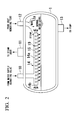
Fig. 2 is a lateral cross-sectional view of a coolant drum shown inFig. 1 . -
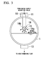
Fig. 3 is a cross-sectional view in a width direction of the coolant drum given inFig.1 . -
Fig. 4 is the other cross-sectional view in a longitudinal direction of a coolant drum of one reference example in the present invention. - Hereinafter, an explanation will be made for an embodiment which is the best mode of the present invention by referring to the
drawings 1 to 4. It is noted that inFig. 2 and subsequent drawings, the constituents the same as those appearing in the flowchart ofFig. 1 will be given the same reference signs, with an explanation omitted here. - As shown in
Fig. 1 , atemperature control system 20 feeds water (a liquid coolant) stored in thecoolant drum 1 in a vapor-liquid equilibrium state by a pump 4 from the bottom of thecoolant drum 1 to a heat removing tube (heat removing unit) 7 inside areactor 5 which carries out the Fischer-Tropsch synthesis reaction (an exothermic reaction) and allows the water to partially evaporate inside theheat removing tube 7 by reaction heat associated with the exothermic reaction which occurred in thereactor 5, thereby recovering the reaction heat. - Further, a mixed phase fluid made up of steam and water in which the water has partially evaporated in the
heat removing tube 7 is returned to thecoolant drum 1 through areturn line 12 leading to thecoolant drum 1, while the steam is supplied to a steam user outside the system through asteam outlet line 11. A steam trap (not shown) may be installed downstream from thesteam outlet line 11. - Still further, refilled water (a liquid coolant) in an amount corresponding to the steam supplied outside the system is refilled through a refilled
water line 10. A refilled amount of the refilled water is adjusted by alevel adjusting valve 2 based on determination results by alevel determination unit 17 which determines a water level (liquid level) inside thecoolant drum 1. - In the above-described flowchart, based on determination results by a temperature determining unit 6 which determines a temperature inside the
reactor 5 which carries out an exothermic reaction, apressure controller 18 which controls the pressure inside thereactor 5 adjusts an amount of steam supplied from thesteam outlet line 11 to outside by cascade control, thereby controlling the temperature of thereactor 5 which carries out the exothermic reaction. The temperature determining unit 6 may be provided with a plurality of temperature sensors (not shown) which are arranged apart from each other in a vertical direction, for example, on thereactor 5. It is, thereby, possible to determine a mean value of individual temperatures determined by these temperature sensors as the temperature inside thereactor 5.
Hereinafter, a detailed explanation will be made for the above-described control. - A steam phase (gas phase unit) and a water phase (liquid phase unit) inside the
coolant drum 1 are kept in a vapor-liquid equilibrium state. Therefore, the pressure of the steam phase inside thecoolant drum 1 and the temperature of the water phase inside thecoolant drum 1 are kept so as to give a constant correlation.
Therefore, where a difference is found between the actual temperature inside thereactor 5 determined by the temperature determining unit 6 and a preset temperature value of thereactor 5 which carries out an exothermic reaction, thepressure controller 18 is actuated to change the pressure of the steam phase inside thecoolant drum 1. - Here, in the present embodiment, the
pressure controller 18 controls thesteam outlet line 11, a pressure adjusting valve 3 installed on thesteam outlet line 11, and a pressure setting unit 9 which sets the pressure inside thecoolant drum 1 via thesteam outlet line 11 by controlling the pressure adjusting valve 3. Determination results made by the temperature determining unit 6 are sent out to the pressure setting unit 9. Also, the pressure setting unit 9 calculates a difference between the actual temperature and a preset temperature value inside thereactor 5 from the determination results, thereby controlling the pressure adjusting valve 3 based on the difference and changing the pressure of the steam phase inside thecoolant drum 1. - As described so far, the steam phase inside the
coolant drum 1 is changed in pressure, by which the water phase inside thecoolant drum 1 is changed in temperature (that is, the temperature of water supplied to theheat removing tube 7 inside thereactor 5 which carries out an exothermic reaction), thus making it possible to change the amount of heat recovered by theheat removing tube 7. Then, it is possible to bring the temperature of thereactor 5 which carries out the exothermic reaction closer to a preset temperature value. - In the present embodiment, the temperature of the water phase inside the
coolant drum 1 can be determined by a thermometer 8 installed at an end of thecoolant drum 1 side in aline 13 through which water is supplied from thecoolant drum 1 to theheat removing tube 7 by using the pump 4. Further, in the present embodiment, thecoolant drum 1, theline 13, theheat removing tube 7, and thereturn line 12 constitute the system through which water as a liquid coolant is circulated. - Next, an explanation will be given in detail for the
coolant drum 1 of thetemperature control system 20.
As shown inFig. 2 andFig. 3 , inside thecoolant drum 1, a refilled water line internal port (coolant refilling unit) 14 connected to the refilledwater line 10 is extended along the longitudinal direction of thecoolant drum 1. The refilled water lineinternal port 14 is arranged in the steam phase.
One or more holes (through holes) 15 are formed on aside wall 14a of the refilled water lineinternal port 14 along an axis direction thereof, and one ormore holes 15 are also formed at anend 14b of the port. Then, theseholes 15 constitute sprinkling units (spray units) 19 which sprinkle (spray) refilled water from the refilled water lineinternal port 14 into the steam phase. It is noted that thehole 15 may be a sprinkling nozzle. - Further, a return line
internal port 12a connected to thereturn line 12 is also installed inside the steam phase of thecoolant drum 1. A mixed phase fluid made up of steam and water, some of which has evaporated in theheat removing tube 7 is supplied into thecoolant drum 1 from the return lineinternal port 12a. The return lineinternal port 12a is positioned further above from the refilled water lineinternal port 14 and arranged at a position away from above in the perpendicular direction of the refilled water lineinternal port 14. Then, the return lineinternal port 12a is bent to the refilled water lineinternal port 14, by which steam which has been circulated inside the return lineinternal port 12a is to be supplied toward the refilled water lineinternal port 14. - Next, an explanation will be made for actions of the above-constituted
coolant drum 1.
Refilled water is supplied at a position which is not submerged from the refilled water lineinternal port 14, by which heat is exchanged between the refilled water lower in temperature and steam which is in a steam phase, thus avoiding a situation in which the refilled water flows, as it is still cool, to the bottom of thecoolant drum 1. Further, the refilled water is sprinkled through theholes 15 on theside wall 14a and theend 14b of the refilled water lineinternal port 14. Thereby, the refilled water can be in contact with steam at a greater area to improve the efficiency of heat exchange, and heat can be exchanged more efficiently between the refilled water which is lower in temperature and the steam which is higher in temperature. Thus, no difference is found between the temperature of the steam phase and the water phase, and the pressure of the steam phase inside thecoolant drum 1 and the temperature of the water phase inside thecoolant drum 1 can be kept constant to give a correlation based on a vapor-liquid equilibrium state. Thus, the temperature can be controlled by thetemperature control system 20 with high accuracy. - As shown in the reference example in
Fig. 4 , when the refilled water lineinternal port 14 is submerged into thecoolant drum 1, the lower-temperature refilled water greater in specific gravity hardly flows out from side holes 16 which is formed in a wall of the refilled water lineinternal port 14 but flows directly to the bottom of thecoolant drum 1. Therefore, a temperature difference takes place between the steam phase and the water phase inside thecoolant drum 1. Then, the pressure of the steam phase inside thecoolant drum 1 is not properly correlated with the temperature of the water phase inside thecoolant drum 1, thus resulting in a risk that thetemperature control system 20 may not control the temperature with high accuracy. - The present invention shall not be technically restricted to the above-described embodiment but may be modified in various ways within a scope not departing from the gist of the present invention.
For example, in the above embodiment, the Fischer-Tropsch synthesis reaction is carried out inside thereactor 5. However, as long as an exothermic reaction is carried out inside thereactor 5, the reaction may not be the Fischer-Tropsch synthesis reaction. - Further, in the above embodiment, as shown in
Fig. 1 , a post-reaction fluid (a reaction product) is introduced from the top of thereactor 5. However, a position in which the post-reaction fluid is introduced from thereactor 5 can be changed, whenever necessary. For example, the post-reaction fluid may be introduced from a body (side wall) or a bottom of thereactor 5. The post-reaction fluid may be introduced from a plurality of sites such as the top, the body and the bottom of thereactor 5. A position from which the post-reaction product is introduced may be changed depending on, for example, a type of exothermic reaction inside thereactor 5. - Further, in the above embodiment, water is used as a liquid coolant but any coolant other than water may be used.
In the above embodiment, a mixed-phase fluid made up of steam and water, some of which has evaporated at theheat removing tube 7 is to return to thecoolant drum 1 through thereturn line 12. However, the mixed phase fluid may not return to thecoolant drum 1. - In addition, a constituent of the above embodiment can be substituted with a known constituent within a scope not departing from the gist of the present invention, or the modified examples may be combined whenever necessary.
- The present invention may be applicable to any coolant drum in general which is attached to a system which allows water supplied to a heat removing tube to partially evaporate in a reactor for carrying out an exothermic reaction to recover reaction heat, thereby controls the reactor or a reaction temperature in itself.
-
- 1: Coolant drum
- 2: Level adjusting valve
- 3: Pressure adjusting valve
- 4: Pump
- 5: Reactor
- 6: Temperature determining unit
- 7: Heat removing tube
- 8: Thermometer
- 9: Pressure setting unit
- 10: Refilled water line
- 11: Steam outlet line
- 12: Return line
- 12a: Return line internal port
- 13: line
- 14: Refilled water line internal port
- 14a: Side wall
- 14b: End of refilled water line internal port
- 15: Hole
- 16: Side hole
- 17: Level determination unit
- 18: Pressure controller
- 20: Temperature control system
Claims (5)
- A temperature control system for recovering reaction heat inside a reactor in which an exothermic reaction takes place, thereby controlling a temperature inside the reactor, the temperature control system comprising:a coolant drum in which a liquid coolant is accommodated in a vapor-liquid equilibrium state;a heat removing unit which is disposed on the reactor to internally circulate the liquid coolant supplied from the coolant drum;a temperature determining unit which determines a temperature inside the reactor; anda pressure controller which controls pressure inside the coolant drum, whereinthe pressure controller controls the pressure inside the coolant drum based on a difference between an actual temperature inside the reactor determined by the temperature determining unit and a preset temperature value inside the reactor, thereby controlling the temperature of the liquid coolant inside the coolant drum.
- The temperature control system according to Claim 1, wherein
the exothermic reaction is the Fischer-Tropsch synthesis reaction. - The temperature control system according to Claim 1 or Claim 2, wherein
a coolant refilling unit which refills the liquid coolant into the coolant drum is installed inside the coolant drum, and
the coolant refilling unit is disposed inside a gas phase unit of the coolant drum. - The temperature control system according to Claim 3, wherein
a spray unit which sprays the liquid coolant to the gas phase unit is formed at the coolant refilling unit. - The temperature control system according to Claim 4, wherein
the coolant refilling unit is formed in a tubular shape and
the spray unit includes a through hole which is formed at the coolant refilling unit.
Applications Claiming Priority (2)
| Application Number | Priority Date | Filing Date | Title |
|---|---|---|---|
| JP2011018263A JP5802397B2 (en) | 2011-01-31 | 2011-01-31 | Temperature control system |
| PCT/JP2012/050853 WO2012105311A1 (en) | 2011-01-31 | 2012-01-17 | Temperature control system |
Publications (2)
| Publication Number | Publication Date |
|---|---|
| EP2671635A1 true EP2671635A1 (en) | 2013-12-11 |
| EP2671635A4 EP2671635A4 (en) | 2015-01-07 |
Family
ID=46602531
Family Applications (1)
| Application Number | Title | Priority Date | Filing Date |
|---|---|---|---|
| EP12742759.9A Withdrawn EP2671635A4 (en) | 2011-01-31 | 2012-01-17 | TEMPERATURE CONTROL SYSTEM |
Country Status (11)
| Country | Link |
|---|---|
| US (1) | US20130306299A1 (en) |
| EP (1) | EP2671635A4 (en) |
| JP (1) | JP5802397B2 (en) |
| CN (1) | CN103338854B (en) |
| AU (1) | AU2012212845B2 (en) |
| BR (1) | BR112013018529A2 (en) |
| CA (1) | CA2825147C (en) |
| EA (1) | EA026314B1 (en) |
| MY (1) | MY164095A (en) |
| WO (1) | WO2012105311A1 (en) |
| ZA (1) | ZA201305535B (en) |
Cited By (1)
| Publication number | Priority date | Publication date | Assignee | Title |
|---|---|---|---|---|
| CN111774021A (en) * | 2019-04-04 | 2020-10-16 | 应急管理部化学品登记中心 | Reaction kettle and application thereof |
Families Citing this family (6)
| Publication number | Priority date | Publication date | Assignee | Title |
|---|---|---|---|---|
| JP5815324B2 (en) * | 2011-08-05 | 2015-11-17 | 独立行政法人石油天然ガス・金属鉱物資源機構 | Temperature control system |
| EP2937657B1 (en) * | 2014-04-25 | 2019-11-27 | Franke Technology and Trademark Ltd | Heat exchanger |
| KR102425630B1 (en) | 2014-10-20 | 2022-07-27 | 벨로시스 테크놀로지스 리미티드 | Process of removing heat |
| CN105806091B (en) * | 2014-12-31 | 2018-03-06 | 国家电网公司 | Gas power station open cooling water system and its start-up and shut-down control method |
| KR102132581B1 (en) * | 2018-03-06 | 2020-08-05 | 한국가스공사 | Method of estimating internal temperature of reformer |
| CN110274512B (en) * | 2019-07-15 | 2024-05-03 | 北京凯瑞英科技有限公司 | Reactor system and process for precisely controlling thermal reaction temperature |
Family Cites Families (24)
| Publication number | Priority date | Publication date | Assignee | Title |
|---|---|---|---|---|
| JPH03127625A (en) * | 1989-10-13 | 1991-05-30 | Tlv Co Ltd | Steam heating and vaporization cooling equipment |
| JPH06257703A (en) * | 1993-03-05 | 1994-09-16 | Toshiba Corp | Exhaust heat recovery boiler |
| US5869011A (en) * | 1994-02-01 | 1999-02-09 | Lee; Jing Ming | Fixed-bed catalytic reactor |
| JP3203407B2 (en) * | 1994-05-14 | 2001-08-27 | 株式会社テイエルブイ | Decompression evaporative cooling system |
| DE4435839A1 (en) * | 1994-10-07 | 1996-04-11 | Bayer Ag | Sludge phase reactor and its use |
| JPH08200915A (en) * | 1995-01-30 | 1996-08-09 | Ikegami Kanagata Kogyo Kk | Cooler |
| US5561987A (en) * | 1995-05-25 | 1996-10-08 | American Standard Inc. | Falling film evaporator with vapor-liquid separator |
| JPH10182103A (en) * | 1996-12-20 | 1998-07-07 | Toyota Motor Corp | Carbon monoxide selective oxidizer, fuel reformer, and fuel cell system |
| FR2768740B1 (en) * | 1997-09-19 | 2001-07-06 | Bp Chem Int Ltd | CONTINUOUS POLYMERIZATION PROCESS OF A VINYL MONOMER |
| US6306917B1 (en) * | 1998-12-16 | 2001-10-23 | Rentech, Inc. | Processes for the production of hydrocarbons, power and carbon dioxide from carbon-containing materials |
| US6516627B2 (en) * | 2001-05-04 | 2003-02-11 | American Standard International Inc. | Flowing pool shell and tube evaporator |
| US7108835B2 (en) * | 2003-10-08 | 2006-09-19 | Rentech, Inc. | Fischer-tropsch slurry reactor cooling tube arrangement |
| KR100903685B1 (en) * | 2004-10-13 | 2009-06-18 | 요크 인터내셔널 코포레이션 | Falling film evaporator |
| NL2000031C2 (en) | 2005-03-17 | 2007-06-14 | Sasol Tech Pty Ltd | Production of liquid and, optionally, gaseous products from gaseous reactants. |
| US20070131583A1 (en) * | 2005-12-13 | 2007-06-14 | Syntroleum Corporation | Fischer-Tropsch product condensing process for cold climates |
| TWI320094B (en) * | 2006-12-21 | 2010-02-01 | Spray type heat exchang device | |
| EP2199368B8 (en) * | 2007-09-27 | 2013-09-11 | Nippon Steel & Sumikin Engineering Co., Ltd. | Bubble-column-type hydrocarbon synthesis reactor, and hydrocarbon synthesis reaction system having the reactor |
| EP2232166B1 (en) * | 2008-01-11 | 2012-04-18 | Johnson Controls Technology Company | Vapor compression system |
| WO2010038400A1 (en) * | 2008-09-30 | 2010-04-08 | 独立行政法人石油天然ガス・金属鉱物資源機構 | System for separating catalyst |
| CA2738126C (en) * | 2008-09-30 | 2014-01-28 | Japan Oil, Gas And Metals National Corporation | Hydrocarbon synthesis reaction apparatus, hydrocarbon synthesis reaction system, and hydrocarbon synthesizing method |
| CA2737881C (en) * | 2008-09-30 | 2014-09-02 | Japan Oil, Gas And Metals National Corporation | Hydrocarbon compound synthesis reaction unit and operating method thereof |
| CN101575044A (en) * | 2009-06-11 | 2009-11-11 | 上海宝钢工程技术有限公司 | Method for controlling temperature of crude oil for emulsion of rolling mill and control device |
| CN201672834U (en) * | 2010-03-24 | 2010-12-15 | 浙江西子联合工程有限公司 | Temperature-control variable-pressure type heat reservoir control system |
| JP5815324B2 (en) * | 2011-08-05 | 2015-11-17 | 独立行政法人石油天然ガス・金属鉱物資源機構 | Temperature control system |
-
2011
- 2011-01-31 JP JP2011018263A patent/JP5802397B2/en not_active Expired - Fee Related
-
2012
- 2012-01-17 BR BR112013018529A patent/BR112013018529A2/en not_active IP Right Cessation
- 2012-01-17 EA EA201391020A patent/EA026314B1/en not_active IP Right Cessation
- 2012-01-17 WO PCT/JP2012/050853 patent/WO2012105311A1/en not_active Ceased
- 2012-01-17 CA CA2825147A patent/CA2825147C/en not_active Expired - Fee Related
- 2012-01-17 CN CN201280006679.4A patent/CN103338854B/en not_active Expired - Fee Related
- 2012-01-17 EP EP12742759.9A patent/EP2671635A4/en not_active Withdrawn
- 2012-01-17 AU AU2012212845A patent/AU2012212845B2/en not_active Ceased
- 2012-01-17 US US13/982,060 patent/US20130306299A1/en not_active Abandoned
- 2012-01-17 MY MYPI2013701276A patent/MY164095A/en unknown
-
2013
- 2013-07-22 ZA ZA2013/05535A patent/ZA201305535B/en unknown
Cited By (1)
| Publication number | Priority date | Publication date | Assignee | Title |
|---|---|---|---|---|
| CN111774021A (en) * | 2019-04-04 | 2020-10-16 | 应急管理部化学品登记中心 | Reaction kettle and application thereof |
Also Published As
| Publication number | Publication date |
|---|---|
| CA2825147C (en) | 2015-11-03 |
| JP5802397B2 (en) | 2015-10-28 |
| JP2012158663A (en) | 2012-08-23 |
| EA026314B1 (en) | 2017-03-31 |
| EA201391020A1 (en) | 2013-12-30 |
| AU2012212845B2 (en) | 2015-05-21 |
| CN103338854A (en) | 2013-10-02 |
| CA2825147A1 (en) | 2012-08-09 |
| WO2012105311A1 (en) | 2012-08-09 |
| ZA201305535B (en) | 2014-10-29 |
| EP2671635A4 (en) | 2015-01-07 |
| BR112013018529A2 (en) | 2016-10-18 |
| MY164095A (en) | 2017-11-30 |
| US20130306299A1 (en) | 2013-11-21 |
| CN103338854B (en) | 2016-01-20 |
Similar Documents
| Publication | Publication Date | Title |
|---|---|---|
| CA2825147C (en) | Temperature control system | |
| US9441165B2 (en) | Temperature control system, hydrocarbon synthesis reaction apparatus, hydrocarbon synthesis reaction system, and temperature control process | |
| AU2008304801B2 (en) | Bubbling tower hydrocarbon reactor and method of detecting slurry surface level | |
| KR102761752B1 (en) | Supercritical water method for upgrading petroleum compositions while reducing clogging | |
| NO317282B1 (en) | Process for operating a column of three-phase bubbles using the Fischer-Tropsch synthesis | |
| KR101242251B1 (en) | Temperature controlling method of the inside of reactor, reaction apparatus and method for manufacturing dimethyl ether | |
| MX2013003395A (en) | Pump around reactor for production of acetic acid. | |
| US6822006B1 (en) | Methods of controlling the temperature of an exothermic reaction | |
| AU2012293758B2 (en) | Temperature control system | |
| TWI606037B (en) | Production of acetic acid with an increased production rate | |
| EA021062B1 (en) | Method for hydrofining naphtha fraction and process for producing hydrocarbon oil | |
| US9688917B2 (en) | Hydrocarbon-producing apparatus and hydrocarbon-producing method | |
| KR102826497B1 (en) | Process for the production of chlorinated hydrocarbons | |
| AU2014206260B2 (en) | Hydrocarbon synthesis reaction apparatus | |
| KR20040055808A (en) | Process for the hydrogenation of acetone | |
| RU1828756C (en) | Method for automatic regulation of distillation process, mainly, stabilization and dehydration of hydrocarbon fractions from reforming | |
| Kim et al. | Dynamics study for oscillatory temperature in methanol partial oxidation | |
| CN117120408A (en) | Method and system for producing acetic acid |
Legal Events
| Date | Code | Title | Description |
|---|---|---|---|
| PUAI | Public reference made under article 153(3) epc to a published international application that has entered the european phase |
Free format text: ORIGINAL CODE: 0009012 |
|
| 17P | Request for examination filed |
Effective date: 20130821 |
|
| AK | Designated contracting states |
Kind code of ref document: A1 Designated state(s): AL AT BE BG CH CY CZ DE DK EE ES FI FR GB GR HR HU IE IS IT LI LT LU LV MC MK MT NL NO PL PT RO RS SE SI SK SM TR |
|
| AX | Request for extension of the european patent |
Extension state: BA ME |
|
| A4 | Supplementary search report drawn up and despatched |
Effective date: 20141208 |
|
| RIC1 | Information provided on ipc code assigned before grant |
Ipc: F28F 27/00 20060101ALI20141202BHEP Ipc: C10G 2/00 20060101ALI20141202BHEP Ipc: F28D 21/00 20060101ALI20141202BHEP Ipc: B01J 19/00 20060101AFI20141202BHEP |
|
| STAA | Information on the status of an ep patent application or granted ep patent |
Free format text: STATUS: THE APPLICATION HAS BEEN WITHDRAWN |
|
| 18W | Application withdrawn |
Effective date: 20170308 |