EP2671147B1 - Système et procédé de stockage de données avec configuration d'hôte de supports de stockage - Google Patents
Système et procédé de stockage de données avec configuration d'hôte de supports de stockage Download PDFInfo
- Publication number
- EP2671147B1 EP2671147B1 EP12702396.8A EP12702396A EP2671147B1 EP 2671147 B1 EP2671147 B1 EP 2671147B1 EP 12702396 A EP12702396 A EP 12702396A EP 2671147 B1 EP2671147 B1 EP 2671147B1
- Authority
- EP
- European Patent Office
- Prior art keywords
- tape
- data
- host computer
- magnetic tape
- sections
- Prior art date
- Legal status (The legal status is an assumption and is not a legal conclusion. Google has not performed a legal analysis and makes no representation as to the accuracy of the status listed.)
- Active
Links
- 238000000034 method Methods 0.000 title claims description 39
- 238000005192 partition Methods 0.000 claims description 89
- 238000013500 data storage Methods 0.000 claims description 13
- 238000004891 communication Methods 0.000 claims description 12
- WYTGDNHDOZPMIW-RCBQFDQVSA-N alstonine Natural products C1=CC2=C3C=CC=CC3=NC2=C2N1C[C@H]1[C@H](C)OC=C(C(=O)OC)[C@H]1C2 WYTGDNHDOZPMIW-RCBQFDQVSA-N 0.000 claims description 8
- 238000010586 diagram Methods 0.000 description 8
- 230000006870 function Effects 0.000 description 8
- 230000007774 longterm Effects 0.000 description 4
- 238000007726 management method Methods 0.000 description 4
- 230000002093 peripheral effect Effects 0.000 description 3
- 238000012545 processing Methods 0.000 description 2
- 238000000638 solvent extraction Methods 0.000 description 2
- 230000002411 adverse Effects 0.000 description 1
- 230000000712 assembly Effects 0.000 description 1
- 238000000429 assembly Methods 0.000 description 1
- 230000000295 complement effect Effects 0.000 description 1
- 230000001010 compromised effect Effects 0.000 description 1
- 238000005516 engineering process Methods 0.000 description 1
- 230000004807 localization Effects 0.000 description 1
- 238000013507 mapping Methods 0.000 description 1
- 238000012986 modification Methods 0.000 description 1
- 230000004048 modification Effects 0.000 description 1
- 230000003287 optical effect Effects 0.000 description 1
- 238000004806 packaging method and process Methods 0.000 description 1
- 238000011084 recovery Methods 0.000 description 1
Images


Classifications
-
- G—PHYSICS
- G11—INFORMATION STORAGE
- G11B—INFORMATION STORAGE BASED ON RELATIVE MOVEMENT BETWEEN RECORD CARRIER AND TRANSDUCER
- G11B27/00—Editing; Indexing; Addressing; Timing or synchronising; Monitoring; Measuring tape travel
- G11B27/10—Indexing; Addressing; Timing or synchronising; Measuring tape travel
- G11B27/11—Indexing; Addressing; Timing or synchronising; Measuring tape travel by using information not detectable on the record carrier
-
- G—PHYSICS
- G06—COMPUTING; CALCULATING OR COUNTING
- G06F—ELECTRIC DIGITAL DATA PROCESSING
- G06F3/00—Input arrangements for transferring data to be processed into a form capable of being handled by the computer; Output arrangements for transferring data from processing unit to output unit, e.g. interface arrangements
- G06F3/06—Digital input from, or digital output to, record carriers, e.g. RAID, emulated record carriers or networked record carriers
- G06F3/0601—Interfaces specially adapted for storage systems
- G06F3/0602—Interfaces specially adapted for storage systems specifically adapted to achieve a particular effect
- G06F3/0608—Saving storage space on storage systems
-
- G—PHYSICS
- G06—COMPUTING; CALCULATING OR COUNTING
- G06F—ELECTRIC DIGITAL DATA PROCESSING
- G06F3/00—Input arrangements for transferring data to be processed into a form capable of being handled by the computer; Output arrangements for transferring data from processing unit to output unit, e.g. interface arrangements
- G06F3/06—Digital input from, or digital output to, record carriers, e.g. RAID, emulated record carriers or networked record carriers
- G06F3/0601—Interfaces specially adapted for storage systems
- G06F3/0628—Interfaces specially adapted for storage systems making use of a particular technique
- G06F3/0638—Organizing or formatting or addressing of data
- G06F3/0644—Management of space entities, e.g. partitions, extents, pools
-
- G—PHYSICS
- G06—COMPUTING; CALCULATING OR COUNTING
- G06F—ELECTRIC DIGITAL DATA PROCESSING
- G06F3/00—Input arrangements for transferring data to be processed into a form capable of being handled by the computer; Output arrangements for transferring data from processing unit to output unit, e.g. interface arrangements
- G06F3/06—Digital input from, or digital output to, record carriers, e.g. RAID, emulated record carriers or networked record carriers
- G06F3/0601—Interfaces specially adapted for storage systems
- G06F3/0668—Interfaces specially adapted for storage systems adopting a particular infrastructure
- G06F3/0671—In-line storage system
- G06F3/0683—Plurality of storage devices
- G06F3/0686—Libraries, e.g. tape libraries, jukebox
-
- G—PHYSICS
- G11—INFORMATION STORAGE
- G11B—INFORMATION STORAGE BASED ON RELATIVE MOVEMENT BETWEEN RECORD CARRIER AND TRANSDUCER
- G11B27/00—Editing; Indexing; Addressing; Timing or synchronising; Monitoring; Measuring tape travel
- G11B27/10—Indexing; Addressing; Timing or synchronising; Measuring tape travel
- G11B27/19—Indexing; Addressing; Timing or synchronising; Measuring tape travel by using information detectable on the record carrier
- G11B27/28—Indexing; Addressing; Timing or synchronising; Measuring tape travel by using information detectable on the record carrier by using information signals recorded by the same method as the main recording
- G11B27/30—Indexing; Addressing; Timing or synchronising; Measuring tape travel by using information detectable on the record carrier by using information signals recorded by the same method as the main recording on the same track as the main recording
- G11B27/3027—Indexing; Addressing; Timing or synchronising; Measuring tape travel by using information detectable on the record carrier by using information signals recorded by the same method as the main recording on the same track as the main recording used signal is digitally coded
-
- G—PHYSICS
- G06—COMPUTING; CALCULATING OR COUNTING
- G06F—ELECTRIC DIGITAL DATA PROCESSING
- G06F11/00—Error detection; Error correction; Monitoring
- G06F11/07—Responding to the occurrence of a fault, e.g. fault tolerance
- G06F11/14—Error detection or correction of the data by redundancy in operation
- G06F11/1402—Saving, restoring, recovering or retrying
- G06F11/1446—Point-in-time backing up or restoration of persistent data
- G06F11/1448—Management of the data involved in backup or backup restore
-
- G—PHYSICS
- G06—COMPUTING; CALCULATING OR COUNTING
- G06F—ELECTRIC DIGITAL DATA PROCESSING
- G06F11/00—Error detection; Error correction; Monitoring
- G06F11/07—Responding to the occurrence of a fault, e.g. fault tolerance
- G06F11/14—Error detection or correction of the data by redundancy in operation
- G06F11/1402—Saving, restoring, recovering or retrying
- G06F11/1446—Point-in-time backing up or restoration of persistent data
- G06F11/1458—Management of the backup or restore process
-
- G—PHYSICS
- G06—COMPUTING; CALCULATING OR COUNTING
- G06F—ELECTRIC DIGITAL DATA PROCESSING
- G06F2213/00—Indexing scheme relating to interconnection of, or transfer of information or other signals between, memories, input/output devices or central processing units
- G06F2213/0038—System on Chip
-
- G—PHYSICS
- G06—COMPUTING; CALCULATING OR COUNTING
- G06F—ELECTRIC DIGITAL DATA PROCESSING
- G06F3/00—Input arrangements for transferring data to be processed into a form capable of being handled by the computer; Output arrangements for transferring data from processing unit to output unit, e.g. interface arrangements
- G06F3/06—Digital input from, or digital output to, record carriers, e.g. RAID, emulated record carriers or networked record carriers
- G06F3/0601—Interfaces specially adapted for storage systems
- G06F3/0628—Interfaces specially adapted for storage systems making use of a particular technique
-
- G—PHYSICS
- G06—COMPUTING; CALCULATING OR COUNTING
- G06F—ELECTRIC DIGITAL DATA PROCESSING
- G06F3/00—Input arrangements for transferring data to be processed into a form capable of being handled by the computer; Output arrangements for transferring data from processing unit to output unit, e.g. interface arrangements
- G06F3/06—Digital input from, or digital output to, record carriers, e.g. RAID, emulated record carriers or networked record carriers
- G06F3/0601—Interfaces specially adapted for storage systems
- G06F3/0668—Interfaces specially adapted for storage systems adopting a particular infrastructure
- G06F3/0671—In-line storage system
- G06F3/0673—Single storage device
- G06F3/0682—Tape device
-
- G—PHYSICS
- G11—INFORMATION STORAGE
- G11B—INFORMATION STORAGE BASED ON RELATIVE MOVEMENT BETWEEN RECORD CARRIER AND TRANSDUCER
- G11B20/00—Signal processing not specific to the method of recording or reproducing; Circuits therefor
- G11B20/10—Digital recording or reproducing
- G11B20/12—Formatting, e.g. arrangement of data block or words on the record carriers
- G11B2020/1291—Formatting, e.g. arrangement of data block or words on the record carriers wherein the formatting serves a specific purpose
- G11B2020/1294—Increase of the access speed
-
- G—PHYSICS
- G11—INFORMATION STORAGE
- G11B—INFORMATION STORAGE BASED ON RELATIVE MOVEMENT BETWEEN RECORD CARRIER AND TRANSDUCER
- G11B2220/00—Record carriers by type
- G11B2220/90—Tape-like record carriers
- G11B2220/95—Serpentine format, wherein a single track or group of tracks traverses the tape plural times from one end to the other
Definitions
- the present disclosure relates to systems and methods for providing configurable access to storage media.
- Network servers and other host computers may use different types of peripheral storage devices having different capacities, access times, and other operating characteristics suitable for various applications.
- Enterprise and data center solutions may employ multiple complementary data storage devices to achieve desired data availability, reliability, security, long-term accessibility, and cost effectiveness, among other considerations.
- Many networks use an automated schedule to archive data for long-term storage.
- Long-term storage devices may be implemented using a wide variety of storage technologies including magnetic and optical disk drives, solid-state drives, tape drives, or other types of storage devices. However, compromises among performance, capacity, and cost are often required.
- Tape drives continue to provide cost-effective, reliable, and energy efficient long-term data storage, particularly for high-volume backups, long-life archives, disaster recovery/business continuity, compliance, and various other applications that include inactive data.
- Discrete tape partitioning involves dividing a storage tape into multiple discrete partitions to address the time and expense required in reclaiming storage tapes by allowing a particular partition to be rewritten once data has expired from that partition.
- data stored within a particular partition must still be appended to any previously stored data, which may affect time required for storage and subsequent retrieval of the data.
- discrete tape partitioning has existed for many years, it has significant drawbacks and has been unpopular with developers as it requires the host to track which partitions contain valid data as well as the locations of the data objects or host files stored within the tape partitions.
- the host application is involved in processing at the end of each partition to properly direct an archive device (e.g., a tape drive) to the next applicable partition in both read and write operations.
- US 5,485 321 A describes A performance optimized computer data recording media format and associated control logic method is disclosed.
- Localized data block recording such as by concurrent parallel or serpentine recording techniques, is used to create a series of Virtual Volumes on a single physical volume. Physical localization of data blocks records is achieved which tends to minimize access time.
- Virtual Volume construct other industry standard data storage systems can be emulated. Many data storage operations requesting physical motion are translated into virtual motion which in turn results in significantly less physical motion than that requested, thereby reducing access times and media and drive apparatus wear.
- this document does not teach, at least, receiving by a tape drive a mask from a host computer that designates writable partitions on the magnetic tape, wherein writing data includes writing data only to partitions designated by the mask received from the host computer.
- a method for storing and retrieving data on a magnetic tape accessed by a tape drive having an associated tape drive processor in communication with a host computer having an associated host processor includes reading or writing data in at least one partition within a logical volume having an associated number of sections designated by the host computer from a predetermined number of sections associated with the magnetic tape, wherein each partition extends across one section.
- a method for archiving data from a host computer to one of a plurality of magnetic tapes loadable into a tape drive in communication with the host computer includes communicating information from the host computer to the tape drive to enable host computer configuration of an associated magnetic tape.
- the method also includes dividing a data area of the associated magnetic tape into a plurality of sections, each section having a plurality of partitions, each partition extending substantially entirely across an associated section, the partitions within a section arranged generally across a width of the magnetic tape, associating at least one of the plurality of sections with a logical data volume designated by the host computer, and writing data from the logical data volume to the partitions within the at least one associated section.
- the method also includes communicating a writable partition mask from the host computer to the tape drive, wherein writing data includes controlling writing of data using a tape drive processor such that data is written to partitions designated by the writable partition mask.
- the writable partition mask designates logically adjacent partitions such that the tape drive moves from one partition to a logically adjacent partition without requiring additional host computer communication.
- writing data includes reversing tape direction at section boundaries to write data in a serpentine fashion within the at least one section assigned by the host computer to a corresponding logical volume.
- the host computer has flexibility to associate a subset of the plurality of sections available on the magnetic tape to balance data access time and storage capacity.
- Embodiments according to the present disclosure may also include a computer data storage system having a tape drive including an associated processor and memory for writing and reading data on an associated magnetic tape, the tape drive receiving information from a host computer to enable host computer configuration of the magnetic tape, allocating a data area of the magnetic tape to a plurality of sections, each section having a plurality of partitions, each partition extending substantially entirely across an associated section, and the partitions within a section arranged generally across a width of the magnetic tape, wherein the tape drive writes data received from the host computer to at least one section associated with a logical volume designated by the host computer.
- the computer data storage system may also include a host computer in communication with the tape drive with the host computer including a map that associates a logical volume with at least one of the plurality of sections.
- Embodiments according to the present disclosure provide various advantages. For example, systems and methods for reading and writing data to magnetic tape according to the present disclosure allow the host computer to configure the magnetic tape storage based on a selected operating point that balances data access time and storage capacity for each logical volume. Embodiments according to the present disclosure allow customers to configure a tape drive using the host computer to meet particular application needs. By managing a library of magnetic tapes, customers can have a variety of capacity/access time characteristics available for different applications. Systems and methods according to the present disclosure provide different fast access storage solutions with a single tape cartridge. The tape cartridge can be sectioned so that users have the flexibility to choose access time and capacity operating points in increments of section size associated with a particular data volume.
- assigning only a single section to a volume provides the fastest access time to the data, but the least amount of storage capacity for the volume. Adding more sections to a volume will make access time slower, but will increase storage capacity for the volume.
- systems or methods according to the present disclosure may be implemented using existing magnetic tape cartridges in many existing tape drive storage systems by updating tape drive firmware without requiring additional hardware components.
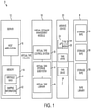
- system 10 includes a host computer or server 12 (e.g., a mainframe server) having an associated memory 14 and microprocessor that runs a host application 16.
- Host computer 12 may be used to manage or coordinate control of data storage in one or more logical data volumes that may also be referred to as virtual tape volumes (VTVs).
- An optional virtual storage management module 18 may be used in conjunction with one or more associated archive devices 20.
- Virtual storage management module 18 may reside within host computer or server 12, or it may be located independent of the server 12 at any appropriate network location depending on the particular application and implementation, for example.
- Archive device 20 may include one or more data storage devices 22, such as magnetic tape drives, for example.
- Each storage device 22 may include an associated microprocessor 24 in communication with firmware (FW) 26 and various other types of memory 28.
- firmware firmware
- Virtual storage management module 18 may perform various functions associated with storing and retrieving data from archive device 20.
- virtual storage management module 18 may include a virtual tape storage control system (VTCS) 30 that communicates with host application 16 and directs a virtual tape storage subsystem (VTSS) 32.
- VTCS virtual tape storage control system
- VTSS virtual tape storage subsystem
- the VTSS routes host files either to archive device 20 or to a virtual tape library 34.
- VTVs may be assigned or allocated to corresponding sections and partitions on magnetic media associated with one or more storage tapes or cartridges 36 that are housed within a tape library 38.
- Archive device 20 may access tapes housed within tape library 38 and loaded or mounted manually or using any of a number of automatic devices, including robotic assemblies that assist archive device 20 in selecting, mounting, and dismounting one of the storage tapes 36, for example.
- Virtual tape library 34 may be used to buffer or temporarily cache VTVs, which may ultimately be written to one of more sections of storage tapes 36 as described in greater detail herein.
- host computer 12 includes a writable partition mask 40 and mapping information 42 used to manage data storage on available partitions and to allocate or associate at least one of a plurality of sections on storage tape 36 with a logical data volume designated by host computer 12 via host application 16 or related software, for example.
- system 10 performs a method for storing and retrieving data on a magnetic tape 36 accessed by a tape drive 22 having an associated tape drive processor 24 in communication with a host computer 12 having an associated host processor that includes reading and/or writing data in at least one partition within a logical volume having an associated number of sections designated by host computer 12 from a predetermined number of sections associated with magnetic tape 36, wherein each partition extends across one section.
- archive device 20 and tape drive 22 receive writable partition mask 40 from host computer 12, which designates writable partitions on magnetic tape 36.
- Tape drive processor 24 uses writable mask 40 received from host computer 12 to control writing data only to partitions designated by mask 40 without requiring additional communication with host computer 12.
- Magnetic tape 36 generally includes a beginning-of-tape (BOT) area or region 50, an end-of- tape area 52 and a data area 54.
- BOT 50 is a physical feature of magnetic tape 50 that can be used by tape drive 22 to detect the beginning of the data area 54.
- BOT 50 may also generally refer to the leader portion of magnetic tape 36 that allows the tape to be loaded, threaded through the transport and take-up reel and advanced to data region 54 for subsequent reading or writing data when the volume is mounted.
- EOT 52 may be used by tape drive 22 to detect the end of data region 54 or end of tape.
- a separate end of data designator (not shown) may also be used.
- Traditional tape drives read/write data to the tape by moving the tape from BOT 50 to EOT 52 before reversing the direction of tape travel from EOT 52 to BOT 50 to read/write data in a serpentine fashion.
- various embodiments for archiving data according to the present disclosure include reversing tape direction at section boundaries to read or write data in a serpentine fashion within at least one section associated with a logical volume designated by the host computer as described in greater detail herein.
- Magnetic tape 36 includes a data area 54 that is divided into a plurality of sections 60, 62, 64, 66. Each section 60, 62, 64, 66 extends vertically substantially across the width of tape 36. The predetermined number of sections associated with magnetic tape 36 (four in this example) cumulatively extend across substantially the entire data portion 54 from BOT 50 to EOT 52. In one embodiment, magnetic tape 36 is implemented by a 1 ⁇ 2" wide magnetic tape having a data portion length of about 279 meters with each section 60, 62, 64, 66 having a section length 70 of about 69 meters. Sections 60, 62, 64, and 66, each include a plurality of partitions as generally illustrated and described with respect to Figures 3-5 .
- FIG. 3 is a diagram illustrating a logical magnetic tape layout for a representative tape section according to embodiments of the present disclosure.
- Representative tape section 60 includes a plurality of partitions generally vertically stacked or arranged across the width of tape 36 as generally represented by partitions 80, 82, 84, and 86.
- tape 36 includes automatically linked partitions (ALPs) that include information for identifying a logically adjacent partition such that reading or writing from a designated partition to the logically adjacent partition is controlled by the tape drive processor 24 ( Fig. 1 ) rather than the host computer 12 ( Fig. 1 ), although the host computer communicates a writable mask 40 ( Fig. 1 ) to tape drive 22, which is stored in memory 28.
- Representative partitions 80, 82, 84, 86 extend substantially entirely across the length of an associated section 60. The number of sections per tape and the number of partitions per section may vary by application and implementation.
- Figure 4 is a diagram illustrating a physical magnetic tape layout for a representative logical volume having two sections according to various embodiments of the present disclosure.
- logical volume 90 includes adjacent tape sections 64, 66 each having a plurality of partitions as generally illustrated in Figures 3 and 5 .
- the host computer designates the number of sections to be included in a particular logical volume 90 to balance data access time and storage capacity of a particular volume.
- defining or associating a logical volume with a single section would result in a smaller available storage capacity for that logical volume and faster data access as compared to associating two (or more) sections with the logical volume as illustrated in Figure 4 , resulting in twice the storage capacity but longer data access times.
- magnetic tape 36 generally includes a plurality of data bands, generally represented by data bands 92, 94. Each data band may include a plurality of data tracks, generally represented by tracks 96, for storing data. Tape 36 may also include one or more servo tracks (not shown) that may be used in aligning the read/write heads as known. Data written to a single partition may be spread across multiple tracks within sections 64, 66 associated with a logical data volume 90, depending on the particular size of the tape, number of partitions, number of sections, etc. However, each partition is recorded in only one section.
- partitions 80, 82 may include data recorded on tracks 100, 102, and 104
- partitions 84, 86 may include data recorded on tracks 110, 112, and 114.
- the tape drive controls direction of travel of tape 36 to reverse tape direction at section boundaries associated with a logical volume to read or write data within the logical volume in a serpentine fashion.
- track 100 is read/written from section 64 to section 66, where the tape reverses direction to read/write track 102 from section 66 to section 64, where tape direction is again reversed to read/write track 104 from section 64 to section 66.
- the tape sections and partitions may be allocated such that data is recorded in a single pass per partition, or some other number of passes per partition depending on the particular application and implementation.
- Figure 5 illustrates a logical tape layout for a tape having multiple sections each having multiple partitions associated with a single logical volume according to various embodiments of the present disclosure.
- logical volume 124 of Figure 5 includes two adjacent sections 120, 122.
- Each section 120, 122 includes a plurality of partitions 130, 132, 134, 136, etc.
- each partition 80, 130, etc. fills the width of an associated section 60, 120, respectively, along a corresponding length of tape 36.
- Partitions 130, 132, 134, 136 are logically adjacent and also consecutively numbered in a serpentine fashion in this example. However, logically adjacent partitions may be physically separated on tape 36 and may not be consecutively numbered.
- Figure 6 is a flow chart illustrating operation of one embodiment of a system or method for reading and writing data to a configurable magnetic tape according to the present disclosure.
- the functions represented by the block diagram may be performed by software and/or hardware. Depending upon the particular processing strategy, such as event-driven, interrupt-driven, etc., the various functions may be performed in an order or sequence other than illustrated in the Figure. Similarly, one or more steps or functions may be repeatedly performed, although not explicitly illustrated. Likewise, various functions may be omitted depending on the particular implementation. Various functions known to those of skill in the art may not be explicitly illustrated or described, but are implied by the illustrated blocks or modules.
- the functions illustrated are primarily performed by control logic implemented by software, instructions, or code stored in a computer readable storage medium and executed by a microprocessor-based controller to control operation of the system. While generally illustrated and described with respect to a magnetic tape drive, those of ordinary skill in the art will recognize that various functions may be applicable to various other types of peripheral storage devices.
- a system or method includes a host computer in communication with a tape drive for transferring data to one of a plurality of magnetic tapes loadable into the tape drive.
- the system or method may include communicating information from the host computer to the tape drive to enable host computer configuration of an associated magnetic tape as represented by block 200.
- the system or method may also include dividing a data area of the associated magnetic tape into a plurality of sections, each section having a plurality of partitions, each partition extending substantially entirely across an associated section, the partitions within a section arranged generally across a width of the magnetic tape as represented by block 202.
- Dividing the data area into a plurality of partitions may be performed during writing of data to the tape, or may be performed in advance during a tape initialization process depending on the particular implementation.
- the system or method continue by associating at least one of the plurality of sections with a logical data volume designated by the host computer as represented by block 204, and writing data from the logical data volume to the partitions within the at least one associated section as represented by block 206.
- the system or method includes communicating a writable partition mask from the host computer to the tape drive as represented by block 208.
- the writable partition mask is used by the tape drive to control writing (or reading) of data using the tape drive processor such that data is written to partitions designated by the writable partition mask from the host processor without requiring additional communication with the host computer.
- the system and method may also include reversing tape direction at section boundaries to write data in a serpentine fashion within the at least one section of a corresponding logical volume as represented by block 210.
- each partition may be written in a single pass or in multiple passes.
- a logical volume may be associated with a single section of the tape to provide faster data access.
- tape direction is reversed at each section boundary.
- tape direction is reversed at the section boundaries associated with the first and last section of the logical volume, i.e. at the logical volume boundaries as defined by the associated sections, although each partition is contained within only one section.
- systems and methods for reading and writing data to magnetic tape allow the host computer to configure the magnetic tape storage based on a selected operating point that balances data access time and storage capacity for each logical volume.
- Embodiments according to the present disclosure allow customers to configure a tape drive using the host computer to meet particular application needs. By managing a library of magnetic tapes, customers can have a variety of capacity/access time characteristics available for different applications.
- Systems and methods according to the present disclosure provide different fast access storage solutions with a single tape cartridge. The tape cartridge can be sectioned so that users have the flexibility to choose their access time and capacity operating points in increments of section size associated with a particular data volume.
- systems or methods according to the present disclosure may be implemented using existing magnetic tape cartridges in many existing tape drive storage systems by updating tape drive firmware without requiring additional hardware components.
Claims (12)
- Procédé permettant de stocker et de récupérer des données sur une bande magnétique (36) incluant une zone de données (54) divisée séquentiellement sur la longueur de la bande magnétique en une pluralité de sections (60, 62, 64, 66) pour fournir un nombre prédéterminé de sections associées à la bande magnétique, chaque section comportant une pluralité de partitions (84, 86) agencées sur toute la largeur de la bande magnétique de sorte à ce que chaque partition soit contenue dans une seule section et s'étende pratiquement entièrement sur la longueur de sa section de rétention, ladite bande magnétique faisant l'objet d'accès grâce à un lecteur de bande (22) possédant un processeur associé de lecteur de bande (24) en communication avec un ordinateur hôte (12) possédant un processeur hôte associé, le procédé comprenant :la lecture ou l'écriture de données dans au moins une partition à l'intérieur d'un volume logique comportant un nombre associé de sections désignées par l'ordinateur hôte à partir du nombre prédéterminé de sections associées à la bande magnétique, etla réception par le lecteur de bande d'un masque émis par l'ordinateur hôte qui désigne les partitions inscriptibles sur la bande magnétique, l'écriture de données incluant l'écriture de données uniquement sur les partitions désignées par le masque reçu en provenance de l'ordinateur hôte.
- Procédé selon la revendication 1, dans lequel la bande magnétique inclut un nombre prédéterminé de partitions par section.
- Procédé selon la revendication 2, dans lequel les partitions comprennent des partitions liées automatiquement qui incluent des informations permettant d'identifier une partition logiquement adjacente de sorte à ce que la lecture ou l'écriture depuis la partition désignée sur la partition logiquement adjacente soit commandée par le processeur de lecteur de bande.
- Procédé selon la revendication 1, dans lequel la lecture ou l'écriture de données comprend l'inversion de la direction du défilement de bande à la fin d'une section.
- Procédé selon la revendication 1, comprenant en outre l'association avec un seul volume logique d'une pluralité de sections à partir du nombre prédéterminé de sections associées à la bande magnétique.
- Procédé selon la revendication 5, comprenant en outre la tenue à jour d'une mappe de volume à l'intérieur de l'ordinateur hôte, laquelle mappe des volumes logique sur des sections correspondantes de la bande magnétique.
- Procédé selon la revendication 5, dans lequel la pluralité de sections associées au volume logique unique est en nombre inférieur au nombre prédéterminé de sections associées à la bande magnétique.
- Procédé selon la revendication 1, dans lequel la bande magnétique inclut un début de bande, une fin de bande et une partie de données, et dans lequel le processeur de lecteur de bande inverse la direction du défilement de bande avant d'atteindre la fin de la partie de données.
- Procédé permettant d'archiver des données émises par un ordinateur hôte sur l'une d'une pluralité de bandes magnétiques chargeables dans un lecteur de bande en communication avec l'ordinateur hôte en effectuant le procédé conforme à l'une quelconque des revendications précédentes, le procédé comprenant en outre :
le transfert d'informations depuis l'ordinateur hôte vers le lecteur de bande afin d'activer une configuration d'ordinateur hôte d'une bande magnétique associée. - Système de stockage de données sur ordinateur, comprenant :un lecteur de bande et un ordinateur hôte en communication avec le lecteur de bande,le lecteur de bande possédant un processeur associé et de la mémoire permettant d'écrire et de lire des données sur une bande magnétique associée, la bande magnétique incluant une zone de données (54) divisée séquentiellement sur la longueur de la bande magnétique en une pluralité de sections (60, 62, 64, 66) pour fournir un nombre prédéterminé de sections associées à la bande magnétique, chaque section comportant une pluralité de partitions (84, 86) agencées sur toute la largeur de la bande magnétique de sorte à ce que chaque partition soit contenue dans une seule section et s'étende pratiquement entièrement sur la longueur de sa section de rétention, la bande magnétique étant configurée pour recevoir des informations émises par l'ordinateur hôte afin d'activer une configuration d'ordinateur hôte de la bande magnétique, dans le but d'allouer une zone de données de la bande magnétique à la pluralité de sections, le lecteur de bande étant configuré pour écrire des données reçues de l'ordinateur hôte sur au moins une section associée à un volume logique désigné par l'ordinateur hôte,l'ordinateur hôte incluant une mappe qui associe un volume logique à au moins l'une de la pluralité de sections, l'ordinateur hôte étant configuré pour transférer un masque de partitions inscriptibles sur le lecteur de bande pour désigner les partitions qui sont accessibles à une écriture de données.
- Système de stockage de données sur ordinateur selon la revendication 10, dans lequel le processeur de lecteur de bande est configuré pour positionner la bande pour qu'elle se déplace d'une partition désignée jusqu'à une partition logiquement adjacente.
- Système de stockage de données sur ordinateur selon la revendication 10, dans lequel le processeur de lecteur de bande est configuré pour inverser la direction de bande au niveau de limites de sections afin de lire ou d'écrire des données en zigzaguant à l'intérieur de la ou des sections associées au volume logique désigné par l'ordinateur hôte.
Applications Claiming Priority (2)
| Application Number | Priority Date | Filing Date | Title |
|---|---|---|---|
| US13/018,176 US9378769B2 (en) | 2011-01-31 | 2011-01-31 | System and method for storing data with host configuration of storage media |
| PCT/US2012/022884 WO2012106197A1 (fr) | 2011-01-31 | 2012-01-27 | Système et procédé de stockage de données avec configuration d'hôte de supports de stockage |
Publications (2)
| Publication Number | Publication Date |
|---|---|
| EP2671147A1 EP2671147A1 (fr) | 2013-12-11 |
| EP2671147B1 true EP2671147B1 (fr) | 2022-02-23 |
Family
ID=45562494
Family Applications (1)
| Application Number | Title | Priority Date | Filing Date |
|---|---|---|---|
| EP12702396.8A Active EP2671147B1 (fr) | 2011-01-31 | 2012-01-27 | Système et procédé de stockage de données avec configuration d'hôte de supports de stockage |
Country Status (4)
| Country | Link |
|---|---|
| US (1) | US9378769B2 (fr) |
| EP (1) | EP2671147B1 (fr) |
| JP (1) | JP6042346B2 (fr) |
| WO (1) | WO2012106197A1 (fr) |
Families Citing this family (7)
| Publication number | Priority date | Publication date | Assignee | Title |
|---|---|---|---|---|
| US10146479B1 (en) | 2017-06-30 | 2018-12-04 | EMC IP Holding Company LLC | Mechanism for multiple coexisting configurations support in virtual tape applications |
| US10318155B1 (en) | 2017-06-30 | 2019-06-11 | EMC IP Holding Company LLC | Mechanism for non-disruptive virtual tape drives removal and reconfiguration |
| US10514992B1 (en) * | 2017-06-30 | 2019-12-24 | EMC IP Holding Company LLC | Disaster recovery specific configurations, management, and application |
| US10338814B1 (en) | 2017-06-30 | 2019-07-02 | EMC IP Holding Company LLC | Mechanism for virtual tape libraries non-disruptive configuration |
| US10599446B2 (en) | 2017-10-31 | 2020-03-24 | EMC IP Holding Company LLC | Mechanism for transparent virtual tape engines restart |
| JPWO2022163078A1 (fr) * | 2021-02-01 | 2022-08-04 | ||
| WO2022195984A1 (fr) * | 2021-03-18 | 2022-09-22 | 富士フイルム株式会社 | Dispositif de traitement d'informations, procédé de traitement d'informations, et programme de traitement d'informations |
Citations (2)
| Publication number | Priority date | Publication date | Assignee | Title |
|---|---|---|---|---|
| WO1997027587A1 (fr) * | 1996-01-26 | 1997-07-31 | Exabyte Corporation | Detection precoce de la position de limites dans un enregistrement en serpentin |
| US7620765B1 (en) * | 2006-12-15 | 2009-11-17 | Symantec Operating Corporation | Method to delete partial virtual tape volumes |
Family Cites Families (26)
| Publication number | Priority date | Publication date | Assignee | Title |
|---|---|---|---|---|
| US4467411A (en) * | 1981-03-06 | 1984-08-21 | International Business Machines Corporation | Scheduling device operations in a buffered peripheral subsystem |
| US5206939A (en) * | 1990-09-24 | 1993-04-27 | Emc Corporation | System and method for disk mapping and data retrieval |
| EP0482297B1 (fr) | 1990-10-23 | 1998-04-29 | Tandberg Data Asa | Méthode et appareil pour accès rapide à un bloc logique sur un milieu de bande |
| JP3206939B2 (ja) * | 1991-11-07 | 2001-09-10 | トウシバビデオプロダクツ プライベート リミテッド | カセット装填装置 |
| US5381539A (en) * | 1992-06-04 | 1995-01-10 | Emc Corporation | System and method for dynamically controlling cache management |
| US5613082A (en) * | 1993-06-14 | 1997-03-18 | International Business Machines Corporation | Control of record media using device only accessible control areas and directory of media control marks and error history |
| US5485321A (en) | 1993-12-29 | 1996-01-16 | Storage Technology Corporation | Format and method for recording optimization |
| US5706467A (en) * | 1995-09-05 | 1998-01-06 | Emc Corporation | Sequential cache management system utilizing the establishment of a microcache and managing the contents of such according to a threshold comparison |
| US5592432A (en) * | 1995-09-05 | 1997-01-07 | Emc Corp | Cache management system using time stamping for replacement queue |
| US5872672A (en) * | 1996-02-16 | 1999-02-16 | International Business Machines Corporation | System and method for monitoring and analyzing tape servo performance |
| TW304261B (en) | 1996-03-12 | 1997-05-01 | Ibm | Tape pre-formatting with uniform data storage segments selectively mapped to fixed or variable sized independently addressable data storage partitions |
| EP0913826A1 (fr) * | 1997-10-31 | 1999-05-06 | Hewlett-Packard Company | Protection contre des rayages dans un système de stockage sur bande |
| US6487562B1 (en) * | 1999-12-20 | 2002-11-26 | Emc Corporation | Dynamically modifying system parameters in data storage system |
| US6789162B1 (en) | 2000-10-17 | 2004-09-07 | Sun Microsystems, Inc. | Storage controller configured to select unused regions of a storage device for data storage according to head position |
| US6850381B2 (en) * | 2001-05-01 | 2005-02-01 | International Business Machines Corporation | Apparatus and method for reducing data loss in tape media due to media edge damage on thrown wraps |
| US6715050B2 (en) * | 2001-05-31 | 2004-03-30 | Oracle International Corporation | Storage access keys |
| US7075874B2 (en) * | 2001-07-17 | 2006-07-11 | Hewlett-Packard Development Company, L.P. | Data storage device monitoring system, method and removable data carrier use with data storage systems |
| US6792568B2 (en) * | 2001-07-31 | 2004-09-14 | Hewlett Packard Development Co. Lp | Data transfer and storage device and method |
| US7752620B2 (en) * | 2005-06-06 | 2010-07-06 | International Business Machines Corporation | Administration of locks for critical sections of computer programs in a computer that supports a multiplicity of logical partitions |
| US7280293B2 (en) * | 2005-07-18 | 2007-10-09 | International Business Machines Corporation | Multi-level mapping of tape error recoveries |
| US7769842B2 (en) * | 2006-08-08 | 2010-08-03 | Endl Texas, Llc | Storage management unit to configure zoning, LUN masking, access controls, or other storage area network parameters |
| US20080162813A1 (en) * | 2007-01-02 | 2008-07-03 | International Business Machines Corporation | Multiple logic media drive |
| US9098210B2 (en) | 2009-10-29 | 2015-08-04 | Oracle America, Inc. | Automatically linking partitions on a tape media device |
| US8266280B2 (en) * | 2010-03-17 | 2012-09-11 | International Business Machines Corporation | System and method for a storage area network virtualization optimization |
| US8248723B1 (en) * | 2011-01-31 | 2012-08-21 | Oracle International Corporation | System and method for managing errors on a magnetic tape |
| US9472233B2 (en) * | 2011-01-31 | 2016-10-18 | Oracle International Corporation | System and method for write protecting portions of magnetic tape storage media |
-
2011
- 2011-01-31 US US13/018,176 patent/US9378769B2/en active Active
-
2012
- 2012-01-27 EP EP12702396.8A patent/EP2671147B1/fr active Active
- 2012-01-27 WO PCT/US2012/022884 patent/WO2012106197A1/fr active Application Filing
- 2012-01-27 JP JP2013551367A patent/JP6042346B2/ja active Active
Patent Citations (3)
| Publication number | Priority date | Publication date | Assignee | Title |
|---|---|---|---|---|
| WO1997027587A1 (fr) * | 1996-01-26 | 1997-07-31 | Exabyte Corporation | Detection precoce de la position de limites dans un enregistrement en serpentin |
| US5959800A (en) * | 1996-01-26 | 1999-09-28 | Exabyte Corporation | Early warning for boundary position in serpentine recording |
| US7620765B1 (en) * | 2006-12-15 | 2009-11-17 | Symantec Operating Corporation | Method to delete partial virtual tape volumes |
Also Published As
| Publication number | Publication date |
|---|---|
| JP2014507744A (ja) | 2014-03-27 |
| JP6042346B2 (ja) | 2016-12-14 |
| WO2012106197A1 (fr) | 2012-08-09 |
| EP2671147A1 (fr) | 2013-12-11 |
| US9378769B2 (en) | 2016-06-28 |
| US20120198146A1 (en) | 2012-08-02 |
Similar Documents
| Publication | Publication Date | Title |
|---|---|---|
| EP2671147B1 (fr) | Système et procédé de stockage de données avec configuration d'hôte de supports de stockage | |
| US11056144B2 (en) | System and method for write protecting portions of magnetic tape storage media | |
| US10346078B2 (en) | Method of writing a file to a plurality of media and a storage system thereof | |
| US9262081B2 (en) | Method for reading file using plurality of tape media | |
| US8041921B2 (en) | Apparatus, system, and method for utilizing tape media segmentation | |
| US7864478B2 (en) | Verification of a tape data storage cartridge | |
| EP2317428B1 (fr) | Liaison automatique de partitions sur un dispositif de support de bande | |
| US7443629B1 (en) | Apparatus, system, and method for optimizing fast access data storage on segmented tape media | |
| US9159357B2 (en) | Efficient moves via repository | |
| US10497391B1 (en) | Rewinding a tape medium | |
| WO2013054597A1 (fr) | Procédé de détection d'altération de données de lecteur à bande et système de fichier | |
| US20160011792A1 (en) | Media control device and control method | |
| US8248723B1 (en) | System and method for managing errors on a magnetic tape | |
| US8880794B2 (en) | Populating a sparsely allocated memory in a storage array | |
| US8027109B1 (en) | Reuse of partially expired physical tape volume | |
| JP2014215668A (ja) | テープドライブへのデータ書き込み方法、プログラム | |
| AU2017201939B1 (en) | System and method for storing data with host configuration of storage media | |
| AU2012212516A1 (en) | System and method for storing data with host configuration of storage media | |
| JP2009015924A (ja) | 磁気テープ装置、その論理ボリューム割当方法、磁気テープカートリッジ、コンピュータシステム |
Legal Events
| Date | Code | Title | Description |
|---|---|---|---|
| PUAI | Public reference made under article 153(3) epc to a published international application that has entered the european phase |
Free format text: ORIGINAL CODE: 0009012 |
|
| 17P | Request for examination filed |
Effective date: 20130823 |
|
| AK | Designated contracting states |
Kind code of ref document: A1 Designated state(s): AL AT BE BG CH CY CZ DE DK EE ES FI FR GB GR HR HU IE IS IT LI LT LU LV MC MK MT NL NO PL PT RO RS SE SI SK SM TR |
|
| DAX | Request for extension of the european patent (deleted) | ||
| STAA | Information on the status of an ep patent application or granted ep patent |
Free format text: STATUS: EXAMINATION IS IN PROGRESS |
|
| 17Q | First examination report despatched |
Effective date: 20180109 |
|
| STAA | Information on the status of an ep patent application or granted ep patent |
Free format text: STATUS: EXAMINATION IS IN PROGRESS |
|
| GRAP | Despatch of communication of intention to grant a patent |
Free format text: ORIGINAL CODE: EPIDOSNIGR1 |
|
| STAA | Information on the status of an ep patent application or granted ep patent |
Free format text: STATUS: GRANT OF PATENT IS INTENDED |
|
| INTG | Intention to grant announced |
Effective date: 20210208 |
|
| GRAJ | Information related to disapproval of communication of intention to grant by the applicant or resumption of examination proceedings by the epo deleted |
Free format text: ORIGINAL CODE: EPIDOSDIGR1 |
|
| STAA | Information on the status of an ep patent application or granted ep patent |
Free format text: STATUS: EXAMINATION IS IN PROGRESS |
|
| INTC | Intention to grant announced (deleted) | ||
| GRAP | Despatch of communication of intention to grant a patent |
Free format text: ORIGINAL CODE: EPIDOSNIGR1 |
|
| STAA | Information on the status of an ep patent application or granted ep patent |
Free format text: STATUS: GRANT OF PATENT IS INTENDED |
|
| INTG | Intention to grant announced |
Effective date: 20210914 |
|
| GRAS | Grant fee paid |
Free format text: ORIGINAL CODE: EPIDOSNIGR3 |
|
| GRAA | (expected) grant |
Free format text: ORIGINAL CODE: 0009210 |
|
| STAA | Information on the status of an ep patent application or granted ep patent |
Free format text: STATUS: THE PATENT HAS BEEN GRANTED |
|
| AK | Designated contracting states |
Kind code of ref document: B1 Designated state(s): AL AT BE BG CH CY CZ DE DK EE ES FI FR GB GR HR HU IE IS IT LI LT LU LV MC MK MT NL NO PL PT RO RS SE SI SK SM TR |
|
| REG | Reference to a national code |
Ref country code: GB Ref legal event code: FG4D |
|
| REG | Reference to a national code |
Ref country code: CH Ref legal event code: EP |
|
| REG | Reference to a national code |
Ref country code: AT Ref legal event code: REF Ref document number: 1470963 Country of ref document: AT Kind code of ref document: T Effective date: 20220315 |
|
| REG | Reference to a national code |
Ref country code: IE Ref legal event code: FG4D |
|
| REG | Reference to a national code |
Ref country code: DE Ref legal event code: R096 Ref document number: 602012077717 Country of ref document: DE |
|
| REG | Reference to a national code |
Ref country code: LT Ref legal event code: MG9D |
|
| REG | Reference to a national code |
Ref country code: NL Ref legal event code: MP Effective date: 20220223 |
|
| REG | Reference to a national code |
Ref country code: AT Ref legal event code: MK05 Ref document number: 1470963 Country of ref document: AT Kind code of ref document: T Effective date: 20220223 |
|
| PG25 | Lapsed in a contracting state [announced via postgrant information from national office to epo] |
Ref country code: SE Free format text: LAPSE BECAUSE OF FAILURE TO SUBMIT A TRANSLATION OF THE DESCRIPTION OR TO PAY THE FEE WITHIN THE PRESCRIBED TIME-LIMIT Effective date: 20220223 Ref country code: RS Free format text: LAPSE BECAUSE OF FAILURE TO SUBMIT A TRANSLATION OF THE DESCRIPTION OR TO PAY THE FEE WITHIN THE PRESCRIBED TIME-LIMIT Effective date: 20220223 Ref country code: PT Free format text: LAPSE BECAUSE OF FAILURE TO SUBMIT A TRANSLATION OF THE DESCRIPTION OR TO PAY THE FEE WITHIN THE PRESCRIBED TIME-LIMIT Effective date: 20220623 Ref country code: NO Free format text: LAPSE BECAUSE OF FAILURE TO SUBMIT A TRANSLATION OF THE DESCRIPTION OR TO PAY THE FEE WITHIN THE PRESCRIBED TIME-LIMIT Effective date: 20220523 Ref country code: NL Free format text: LAPSE BECAUSE OF FAILURE TO SUBMIT A TRANSLATION OF THE DESCRIPTION OR TO PAY THE FEE WITHIN THE PRESCRIBED TIME-LIMIT Effective date: 20220223 Ref country code: LT Free format text: LAPSE BECAUSE OF FAILURE TO SUBMIT A TRANSLATION OF THE DESCRIPTION OR TO PAY THE FEE WITHIN THE PRESCRIBED TIME-LIMIT Effective date: 20220223 Ref country code: HR Free format text: LAPSE BECAUSE OF FAILURE TO SUBMIT A TRANSLATION OF THE DESCRIPTION OR TO PAY THE FEE WITHIN THE PRESCRIBED TIME-LIMIT Effective date: 20220223 Ref country code: ES Free format text: LAPSE BECAUSE OF FAILURE TO SUBMIT A TRANSLATION OF THE DESCRIPTION OR TO PAY THE FEE WITHIN THE PRESCRIBED TIME-LIMIT Effective date: 20220223 Ref country code: BG Free format text: LAPSE BECAUSE OF FAILURE TO SUBMIT A TRANSLATION OF THE DESCRIPTION OR TO PAY THE FEE WITHIN THE PRESCRIBED TIME-LIMIT Effective date: 20220523 |
|
| PG25 | Lapsed in a contracting state [announced via postgrant information from national office to epo] |
Ref country code: PL Free format text: LAPSE BECAUSE OF FAILURE TO SUBMIT A TRANSLATION OF THE DESCRIPTION OR TO PAY THE FEE WITHIN THE PRESCRIBED TIME-LIMIT Effective date: 20220223 Ref country code: LV Free format text: LAPSE BECAUSE OF FAILURE TO SUBMIT A TRANSLATION OF THE DESCRIPTION OR TO PAY THE FEE WITHIN THE PRESCRIBED TIME-LIMIT Effective date: 20220223 Ref country code: GR Free format text: LAPSE BECAUSE OF FAILURE TO SUBMIT A TRANSLATION OF THE DESCRIPTION OR TO PAY THE FEE WITHIN THE PRESCRIBED TIME-LIMIT Effective date: 20220524 Ref country code: FI Free format text: LAPSE BECAUSE OF FAILURE TO SUBMIT A TRANSLATION OF THE DESCRIPTION OR TO PAY THE FEE WITHIN THE PRESCRIBED TIME-LIMIT Effective date: 20220223 Ref country code: AT Free format text: LAPSE BECAUSE OF FAILURE TO SUBMIT A TRANSLATION OF THE DESCRIPTION OR TO PAY THE FEE WITHIN THE PRESCRIBED TIME-LIMIT Effective date: 20220223 |
|
| PG25 | Lapsed in a contracting state [announced via postgrant information from national office to epo] |
Ref country code: IS Free format text: LAPSE BECAUSE OF FAILURE TO SUBMIT A TRANSLATION OF THE DESCRIPTION OR TO PAY THE FEE WITHIN THE PRESCRIBED TIME-LIMIT Effective date: 20220623 |
|
| PG25 | Lapsed in a contracting state [announced via postgrant information from national office to epo] |
Ref country code: SM Free format text: LAPSE BECAUSE OF FAILURE TO SUBMIT A TRANSLATION OF THE DESCRIPTION OR TO PAY THE FEE WITHIN THE PRESCRIBED TIME-LIMIT Effective date: 20220223 Ref country code: SK Free format text: LAPSE BECAUSE OF FAILURE TO SUBMIT A TRANSLATION OF THE DESCRIPTION OR TO PAY THE FEE WITHIN THE PRESCRIBED TIME-LIMIT Effective date: 20220223 Ref country code: RO Free format text: LAPSE BECAUSE OF FAILURE TO SUBMIT A TRANSLATION OF THE DESCRIPTION OR TO PAY THE FEE WITHIN THE PRESCRIBED TIME-LIMIT Effective date: 20220223 Ref country code: EE Free format text: LAPSE BECAUSE OF FAILURE TO SUBMIT A TRANSLATION OF THE DESCRIPTION OR TO PAY THE FEE WITHIN THE PRESCRIBED TIME-LIMIT Effective date: 20220223 Ref country code: DK Free format text: LAPSE BECAUSE OF FAILURE TO SUBMIT A TRANSLATION OF THE DESCRIPTION OR TO PAY THE FEE WITHIN THE PRESCRIBED TIME-LIMIT Effective date: 20220223 Ref country code: CZ Free format text: LAPSE BECAUSE OF FAILURE TO SUBMIT A TRANSLATION OF THE DESCRIPTION OR TO PAY THE FEE WITHIN THE PRESCRIBED TIME-LIMIT Effective date: 20220223 |
|
| REG | Reference to a national code |
Ref country code: DE Ref legal event code: R097 Ref document number: 602012077717 Country of ref document: DE |
|
| PG25 | Lapsed in a contracting state [announced via postgrant information from national office to epo] |
Ref country code: AL Free format text: LAPSE BECAUSE OF FAILURE TO SUBMIT A TRANSLATION OF THE DESCRIPTION OR TO PAY THE FEE WITHIN THE PRESCRIBED TIME-LIMIT Effective date: 20220223 |
|
| PLBE | No opposition filed within time limit |
Free format text: ORIGINAL CODE: 0009261 |
|
| STAA | Information on the status of an ep patent application or granted ep patent |
Free format text: STATUS: NO OPPOSITION FILED WITHIN TIME LIMIT |
|
| 26N | No opposition filed |
Effective date: 20221124 |
|
| PG25 | Lapsed in a contracting state [announced via postgrant information from national office to epo] |
Ref country code: SI Free format text: LAPSE BECAUSE OF FAILURE TO SUBMIT A TRANSLATION OF THE DESCRIPTION OR TO PAY THE FEE WITHIN THE PRESCRIBED TIME-LIMIT Effective date: 20220223 |
|
| P01 | Opt-out of the competence of the unified patent court (upc) registered |
Effective date: 20230522 |
|
| PG25 | Lapsed in a contracting state [announced via postgrant information from national office to epo] |
Ref country code: IT Free format text: LAPSE BECAUSE OF FAILURE TO SUBMIT A TRANSLATION OF THE DESCRIPTION OR TO PAY THE FEE WITHIN THE PRESCRIBED TIME-LIMIT Effective date: 20220223 |
|
| REG | Reference to a national code |
Ref country code: CH Ref legal event code: PL |
|
| PG25 | Lapsed in a contracting state [announced via postgrant information from national office to epo] |
Ref country code: LU Free format text: LAPSE BECAUSE OF NON-PAYMENT OF DUE FEES Effective date: 20230127 |
|
| REG | Reference to a national code |
Ref country code: BE Ref legal event code: MM Effective date: 20230131 |
|
| PG25 | Lapsed in a contracting state [announced via postgrant information from national office to epo] |
Ref country code: LI Free format text: LAPSE BECAUSE OF NON-PAYMENT OF DUE FEES Effective date: 20230131 Ref country code: CH Free format text: LAPSE BECAUSE OF NON-PAYMENT OF DUE FEES Effective date: 20230131 |
|
| PG25 | Lapsed in a contracting state [announced via postgrant information from national office to epo] |
Ref country code: FR Free format text: LAPSE BECAUSE OF NON-PAYMENT OF DUE FEES Effective date: 20230131 Ref country code: BE Free format text: LAPSE BECAUSE OF NON-PAYMENT OF DUE FEES Effective date: 20230131 |
|
| PGFP | Annual fee paid to national office [announced via postgrant information from national office to epo] |
Ref country code: GB Payment date: 20231207 Year of fee payment: 13 |
|
| PG25 | Lapsed in a contracting state [announced via postgrant information from national office to epo] |
Ref country code: IE Free format text: LAPSE BECAUSE OF NON-PAYMENT OF DUE FEES Effective date: 20230127 |
|
| PGFP | Annual fee paid to national office [announced via postgrant information from national office to epo] |
Ref country code: DE Payment date: 20231205 Year of fee payment: 13 |