EP2670045A2 - Dual generator system - Google Patents
Dual generator system Download PDFInfo
- Publication number
- EP2670045A2 EP2670045A2 EP20130169784 EP13169784A EP2670045A2 EP 2670045 A2 EP2670045 A2 EP 2670045A2 EP 20130169784 EP20130169784 EP 20130169784 EP 13169784 A EP13169784 A EP 13169784A EP 2670045 A2 EP2670045 A2 EP 2670045A2
- Authority
- EP
- European Patent Office
- Prior art keywords
- phase
- output
- generator
- auxiliary
- combined output
- Prior art date
- Legal status (The legal status is an assumption and is not a legal conclusion. Google has not performed a legal analysis and makes no representation as to the accuracy of the status listed.)
- Granted
Links
Images

Classifications
-
- H—ELECTRICITY
- H02—GENERATION; CONVERSION OR DISTRIBUTION OF ELECTRIC POWER
- H02P—CONTROL OR REGULATION OF ELECTRIC MOTORS, ELECTRIC GENERATORS OR DYNAMO-ELECTRIC CONVERTERS; CONTROLLING TRANSFORMERS, REACTORS OR CHOKE COILS
- H02P9/00—Arrangements for controlling electric generators for the purpose of obtaining a desired output
- H02P9/02—Details of the control
-
- H—ELECTRICITY
- H02—GENERATION; CONVERSION OR DISTRIBUTION OF ELECTRIC POWER
- H02P—CONTROL OR REGULATION OF ELECTRIC MOTORS, ELECTRIC GENERATORS OR DYNAMO-ELECTRIC CONVERTERS; CONTROLLING TRANSFORMERS, REACTORS OR CHOKE COILS
- H02P9/00—Arrangements for controlling electric generators for the purpose of obtaining a desired output
- H02P9/14—Arrangements for controlling electric generators for the purpose of obtaining a desired output by variation of field
- H02P9/26—Arrangements for controlling electric generators for the purpose of obtaining a desired output by variation of field using discharge tubes or semiconductor devices
- H02P9/30—Arrangements for controlling electric generators for the purpose of obtaining a desired output by variation of field using discharge tubes or semiconductor devices using semiconductor devices
Definitions
- the present invention is related to electrical generators, and in particular to a dual generator system.
- a generator includes a generator control unit (GCU) that regulates the output of the generator as desired based on the application.
- GCU generator control unit
- the output is regulated by varying the excitation (i.e., current) provided to an excitation winding of the generator.
- this is made more difficult by the presence of an unbalanced load that results in phase to phase differences that cannot be regulated or corrected by modifying the excitation provided to the generator.
- phase to phase differences are handled via active filters connected to the output of the generator.
- active components require additional cooling that increases the cost and decreases the reliability of such systems.
- a dual generator system includes a main generator and an auxiliary generator.
- the main generator generates at least a first phase main output and a second phase main output.
- the auxiliary generator generates at least a first phase auxiliary output and a second phase auxiliary output, wherein the first phase auxiliary output is combined with the first phase main output to generate a first phase main output.
- An auxiliary generator control unit (AGCU) monitors the first phase combined output and the second phase combined output and in response independently regulates the first phase auxiliary output and the second phase auxiliary output.
- Figure 1 is a block diagram of a generator system according to an embodiment of the present invention.
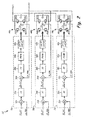
- FIG. 2 is a block diagram of an auxiliary generator control unit (AGCU) according to an embodiment of the present invention.
- the dual generator system of the present invention employs a main generator and an auxiliary generator.
- the output of the main generator is regulated by varying the excitation provided to an exciter winding (in embodiments in which the main generator is a wound field synchronous generator).
- the auxiliary generator generates at least a first phase auxiliary output and a second phase auxiliary output, each of which is independently controllable, such that phase-to-phase imbalances can be corrected by regulating the output of the auxiliary generator.
- the auxiliary generator can supplement the power capabilities of the main generator.
- FIG. 1 is a block diagram of generator system 10 according to an embodiment of the present invention.
- Generator system 10 includes prime mover 12 and dual generator system 14.
- prime mover 12 is an internal combustion engine (ICE), although in other embodiments other machines for generating or communicating mechanical power may be employed.
- Dual generator system 14 includes main generator 16, auxiliary generator 18, main generator control unit (MGCU) 20, auxiliary generator control unit (AGCU) 22, main generator sensors 24, LC filter 26, and combined output sensors 28. Dual generator system 14 supplies electrical power to load 30.
- load 30 is an unbalanced load that, if not corrected, will result in imbalances in the output provided by dual generator system 14.
- shaft 29 communicates mechanical power from prime mover 12 to both main generator 16 and auxiliary generator 18.
- Main generator 16 and auxiliary generator 18 both have the same number of poles and produce same output frequency.
- the positions of main generator 16 and auxiliary generator 18 are aligned such that the outputs provided by both main generator 16 and auxiliary generator 18 are in phase and can therefore be combined.
- main generator 16 and auxiliary generator 18 it is beneficial for main generator 16 and auxiliary generator 18 to share a common shaft (i.e., to maintain operate of both generators at the same speed).
- Main generator 16 provides at least a first phase main output and a second phase main output.
- main generator 16 is a three-phase machine that provides a first phase main output, second phase main output, and third phase main output.
- main generator is a wound field synchronous generator (WFSG).
- WFSG wound field synchronous generator
- MGCU 20 monitors at least the first phase main output (e.g., voltage and/or current) and in response regulates the excitation provided to main generator 16 order to regulate the output to a desired value.
- Auxiliary generator 18 provides at least a first phase auxiliary output and a second phase auxiliary output.
- auxiliary generator 18 is a three-phase machine that provides a first phase auxiliary output, a second phase auxiliary output, and a third phase auxiliary output.
- Each phase of auxiliary generator 18 is independently regulated. That is, the first phase auxiliary output can be regulated independent of the regulation of the second phase auxiliary output, and independent of the regulation of the third phase auxiliary output.
- the output of auxiliary generator 18 is provided to inductive-capacitive (LC) filter 26, which acts to reduce harmonics in the output of auxiliary generator 18. In some applications, LC filter 26 is not required and may be omitted.
- Each auxiliary output phase is combined with a corresponding main output phase to generate a combined output.
- first phase auxiliary output is combined with the first phase main output to generate a first phase combined output.
- second phase auxiliary output is combined with the second phase main output to generate a second phase combined output, and
- third phase auxiliary output is combined with the third phase main output to generate a third phase combined output.
- Combined output sensors 28 monitor the voltage and/or current associated with each phase of the combined outputs, which is provided in feedback to AGCU 22.
- auxiliary generator 18 is a flux-regulated permanent magnet generator (FRPMG).
- FRPMG flux-regulated permanent magnet generator
- the output of the PMG is a function only of the speed of the prime mover to which it is attached.
- a FRPMG (such as that employed by auxiliary generator 18) utilizes an armature winding and at least one control coil, wherein a control signal provided to the control coil varies the magnetic permeability of the flux diverter and therefore varies the output voltage of the FRPMG.
- FRPMG includes a separate control winding for each auxiliary phase output of auxiliary generator 18, allowing each phase of the FRPMG to be separately regulated.
- auxiliary generator 18 includes a plurality of wound field synchronous machines, each WFSG having a separate exciter winding to allow AGCU 22 to independently regulate the output of each WFSG.
- AGCU 22 monitors the combined output of main generator 16 and auxiliary generator 18.
- Sensors 28 may include voltage and/or current sensors for providing feedback regarding the output voltage and/or current of dual generator system 14. Based on detected imbalances in the monitored phases, AGCU 22 regulates, independently, each output phase of auxiliary generator 18 to correct detected imbalances. In addition, AGCU 22 may regulate the output of auxiliary generator 18 to supplement the power provided by main generator 16, either to account for a loss of power associated with main generator 16, or to accommodate greater demand from load 30.
- FIG. 2 is a block diagram of control function implemented by auxiliary generator control unit (AGCU) 22 according to an embodiment of the present invention.
- AGCU 22 includes a plurality of separate control loops 31a, 31b, and 31c, each associated with a particular phase to be regulated.
- Control loops 31a, 31b, and 31c are used to regulate current in the control coils La, Lb, and Lc in response to the voltage regulators output.
- Capacitors C A , C B , and C C minimize ripple in the DC voltage applied across control windings L A , L B , and L C .
- FIG. 2 The embodiment shown in Figure 2 is described with respect to a flux regulated permanent magnet generator (FRPMG), in which a plurality of separate excitation signals (i.e., flux diverter control signal) are provided to corresponding a control windings (e.g., L A , L B , L C ) to regulate the first, second and third phases, respectively, of auxiliary generator 18.
- FRPMG flux regulated permanent magnet generator
- a plurality of separate excitation signals i.e., flux diverter control signal
- a control windings e.g., L A , L B , L C
- WFSGs wound field synchronous generators
- AGCU 22 monitors a voltage feedback VA_fdbk, VB_fbdk, and VC_fdbk provided by sensors 28 (shown in Figure 1 ) representative of the combined voltage output of main generator 16 and auxiliary generator 18.
- Voltage feedback VA_fdbk is provided to control loop 31a
- voltage feedback VB_fdbk is provided to control loop 31b
- voltage feedback VC_fdbk is provided to control loop 31c.
- each control loop 31a, 31b, and 31c regulates current in control windings L A , L B , and L C , respectively.
- the functions performed by each control loop 31a, 31b, and 31c are the same, except for the phase with which each is associated.
- functions performed by control loops 31a, 31b, and 31c may be implemented via a combination of hardware and/or software components.
- control loop 31a monitors voltage feedback VA_fdbk, and compares it at difference block 32a to reference value VA_ref.
- a difference between monitored voltage feedback VA_fdbk and reference value VA_ref is provided to proportional-integral (PI) controller 34a, which generates in response a current reference IA_ref.
- the reference current IA_ref is compared with monitored feedback current IA_fdbk by difference block 36a, wherein monitored feedback current IA_fdbk represents to the current of first control winding L A .
- the resulting difference is provided to PI controller 38a, which generates a signal to minimize the difference.
- the output of PI controller 38a is provided to pulse width modulator (PWM) 40a to generate pulse width modulation (PWM) signals.
- PWM signals are provided to gate drive 42a, to generate gate drive signals for each of the plurality of solid-state switching devices M1-M4 to selectively turn the solid-state devices On and Off to create the desired current in control coil L A .
- a first phase of auxiliary generator 18 is individually controlled to correct imbalances in the combined output of dual generator system 14.
- Control loops 31b and 31c comprise the same elements described with respect to control loop 31a, with similar elements marked with a "b” or “c", respectively.
- control loop 31b includes difference block 32b, PI controller 34b, difference block 36b, PI controller 38b, PWM 40b, gate drive 42b, and H-bridge circuit 44b, which includes solid-state switching devices M1b, M2b, M3b, and M4b.
- control loop 31c includes difference block 32c, PI controller 34c, difference block 36c, PI controller 38c, PWM 40c, gate drive 42c, and H-bridge circuit 44c, which includes solid-state switching devices M1c, M2c, M3c, and M4c.
- Control loop 31b monitors voltage feedback VB_fdbk and compares it to reference voltage VB_ref
- control loop 31c monitors voltage feedback VB_fdbk and compares it to reference voltage VB_ref.
Landscapes
- Engineering & Computer Science (AREA)
- Power Engineering (AREA)
- Control Of Eletrric Generators (AREA)
- Stabilization Of Oscillater, Synchronisation, Frequency Synthesizers (AREA)
Abstract
Description
- The present invention is related to electrical generators, and in particular to a dual generator system.
- Electrical generators are widely employed to convert mechanical energy to electrical energy for distribution to one or more loads. In a typical application, a generator includes a generator control unit (GCU) that regulates the output of the generator as desired based on the application. For example, in a wound field synchronous generator the output is regulated by varying the excitation (i.e., current) provided to an excitation winding of the generator. However, in some applications this is made more difficult by the presence of an unbalanced load that results in phase to phase differences that cannot be regulated or corrected by modifying the excitation provided to the generator. Typically, phase to phase differences are handled via active filters connected to the output of the generator. However, active components require additional cooling that increases the cost and decreases the reliability of such systems.
- A dual generator system includes a main generator and an auxiliary generator. The main generator generates at least a first phase main output and a second phase main output. The auxiliary generator generates at least a first phase auxiliary output and a second phase auxiliary output, wherein the first phase auxiliary output is combined with the first phase main output to generate a first phase main output. An auxiliary generator control unit (AGCU) monitors the first phase combined output and the second phase combined output and in response independently regulates the first phase auxiliary output and the second phase auxiliary output.
-
Figure 1 is a block diagram of a generator system according to an embodiment of the present invention. -
Figure 2 is a block diagram of an auxiliary generator control unit (AGCU) according to an embodiment of the present invention. - The dual generator system of the present invention employs a main generator and an auxiliary generator. The output of the main generator is regulated by varying the excitation provided to an exciter winding (in embodiments in which the main generator is a wound field synchronous generator). The auxiliary generator generates at least a first phase auxiliary output and a second phase auxiliary output, each of which is independently controllable, such that phase-to-phase imbalances can be corrected by regulating the output of the auxiliary generator. In addition, the auxiliary generator can supplement the power capabilities of the main generator.
-
Figure 1 is a block diagram ofgenerator system 10 according to an embodiment of the present invention.Generator system 10 includesprime mover 12 anddual generator system 14. In the embodiment shown inFigure 1 ,prime mover 12 is an internal combustion engine (ICE), although in other embodiments other machines for generating or communicating mechanical power may be employed.Dual generator system 14 includesmain generator 16,auxiliary generator 18, main generator control unit (MGCU) 20, auxiliary generator control unit (AGCU) 22,main generator sensors 24,LC filter 26, and combinedoutput sensors 28.Dual generator system 14 supplies electrical power to load 30. In one embodiment,load 30 is an unbalanced load that, if not corrected, will result in imbalances in the output provided bydual generator system 14. - In the embodiment shown in
Figure 1 ,shaft 29 communicates mechanical power fromprime mover 12 to bothmain generator 16 andauxiliary generator 18.Main generator 16 andauxiliary generator 18 both have the same number of poles and produce same output frequency. The positions ofmain generator 16 andauxiliary generator 18 are aligned such that the outputs provided by bothmain generator 16 andauxiliary generator 18 are in phase and can therefore be combined. To maintain synchronous phase alignment, it is beneficial formain generator 16 andauxiliary generator 18 to share a common shaft (i.e., to maintain operate of both generators at the same speed). -
Main generator 16 provides at least a first phase main output and a second phase main output. In the embodiment shown inFigure 1 ,main generator 16 is a three-phase machine that provides a first phase main output, second phase main output, and third phase main output. In one embodiment, main generator is a wound field synchronous generator (WFSG). In other embodiment, other well-known generator topologies may be employed. The output of a WFSG is dependent on and can therefore be regulated via excitation provided to an exciter or field winding (not shown) ofmain generator 16. MGCU 20 monitors at least the first phase main output (e.g., voltage and/or current) and in response regulates the excitation provided tomain generator 16 order to regulate the output to a desired value. -
Auxiliary generator 18 provides at least a first phase auxiliary output and a second phase auxiliary output. In the embodiment shown inFigure 1 ,auxiliary generator 18 is a three-phase machine that provides a first phase auxiliary output, a second phase auxiliary output, and a third phase auxiliary output. Each phase ofauxiliary generator 18 is independently regulated. That is, the first phase auxiliary output can be regulated independent of the regulation of the second phase auxiliary output, and independent of the regulation of the third phase auxiliary output. The output ofauxiliary generator 18 is provided to inductive-capacitive (LC)filter 26, which acts to reduce harmonics in the output ofauxiliary generator 18. In some applications,LC filter 26 is not required and may be omitted. Each auxiliary output phase is combined with a corresponding main output phase to generate a combined output. For example, first phase auxiliary output is combined with the first phase main output to generate a first phase combined output. Likewise, a second phase auxiliary output is combined with the second phase main output to generate a second phase combined output, and a third phase auxiliary output is combined with the third phase main output to generate a third phase combined output. Combinedoutput sensors 28 monitor the voltage and/or current associated with each phase of the combined outputs, which is provided in feedback toAGCU 22. - In one embodiment,
auxiliary generator 18 is a flux-regulated permanent magnet generator (FRPMG). In a typical permanent magnet generator (PMG), the output of the PMG is a function only of the speed of the prime mover to which it is attached. However, a FRPMG (such as that employed by auxiliary generator 18) utilizes an armature winding and at least one control coil, wherein a control signal provided to the control coil varies the magnetic permeability of the flux diverter and therefore varies the output voltage of the FRPMG. In one embodiment, described in more detail with respect toFigure 2 , FRPMG includes a separate control winding for each auxiliary phase output ofauxiliary generator 18, allowing each phase of the FRPMG to be separately regulated. A FRPMG according to an embodiment of the present invention is described inU.S. Patent Number 8,085,003 , titled "Voltage Regulated Permanent Magnet Generator", by Jacek F. Gieras and Gregory I. Rozman, the entire contents of which are incorporated by reference herein. In other embodiments,auxiliary generator 18 includes a plurality of wound field synchronous machines, each WFSG having a separate exciter winding to allow AGCU 22 to independently regulate the output of each WFSG. - In the embodiment shown in
Figure 1 , AGCU 22 monitors the combined output ofmain generator 16 andauxiliary generator 18.Sensors 28 may include voltage and/or current sensors for providing feedback regarding the output voltage and/or current ofdual generator system 14. Based on detected imbalances in the monitored phases,AGCU 22 regulates, independently, each output phase ofauxiliary generator 18 to correct detected imbalances. In addition, AGCU 22 may regulate the output ofauxiliary generator 18 to supplement the power provided bymain generator 16, either to account for a loss of power associated withmain generator 16, or to accommodate greater demand fromload 30. -
Figure 2 is a block diagram of control function implemented by auxiliary generator control unit (AGCU) 22 according to an embodiment of the present invention. AGCU 22 includes a plurality ofseparate control loops Control loops Figure 2 is described with respect to a flux regulated permanent magnet generator (FRPMG), in which a plurality of separate excitation signals (i.e., flux diverter control signal) are provided to corresponding a control windings (e.g., LA, LB, LC) to regulate the first, second and third phases, respectively, ofauxiliary generator 18. In other embodiments, the excitation signals could be provided to separate exciter windings of a three separate wound field synchronous generators (WFSGs). - In the embodiment shown in
Figure 2 ,AGCU 22 monitors a voltage feedback VA_fdbk, VB_fbdk, and VC_fdbk provided by sensors 28 (shown inFigure 1 ) representative of the combined voltage output ofmain generator 16 andauxiliary generator 18. Voltage feedback VA_fdbk is provided to controlloop 31a, voltage feedback VB_fdbk is provided to controlloop 31b, and voltage feedback VC_fdbk is provided to control loop 31c. In response, eachcontrol loop control loop control loops - For example,
control loop 31a monitors voltage feedback VA_fdbk, and compares it atdifference block 32a to reference value VA_ref. A difference between monitored voltage feedback VA_fdbk and reference value VA_ref is provided to proportional-integral (PI)controller 34a, which generates in response a current reference IA_ref. The reference current IA_ref is compared with monitored feedback current IA_fdbk bydifference block 36a, wherein monitored feedback current IA_fdbk represents to the current of first control winding LA. The resulting difference is provided toPI controller 38a, which generates a signal to minimize the difference. The output ofPI controller 38a is provided to pulse width modulator (PWM) 40a to generate pulse width modulation (PWM) signals. The PWM signals are provided togate drive 42a, to generate gate drive signals for each of the plurality of solid-state switching devices M1-M4 to selectively turn the solid-state devices On and Off to create the desired current in control coil LA. In this way, a first phase ofauxiliary generator 18 is individually controlled to correct imbalances in the combined output ofdual generator system 14. -
Control loops 31b and 31c comprise the same elements described with respect to controlloop 31a, with similar elements marked with a "b" or "c", respectively. For example,control loop 31b includesdifference block 32b,PI controller 34b,difference block 36b,PI controller 38b, PWM 40b,gate drive 42b, and H-bridge circuit 44b, which includes solid-state switching devices M1b, M2b, M3b, and M4b. Similarly, control loop 31c includesdifference block 32c,PI controller 34c,difference block 36c,PI controller 38c, PWM 40c,gate drive 42c, and H-bridge circuit 44c, which includes solid-state switching devices M1c, M2c, M3c, and M4c.Control loop 31b monitors voltage feedback VB_fdbk and compares it to reference voltage VB_ref, and control loop 31c monitors voltage feedback VB_fdbk and compares it to reference voltage VB_ref. While the invention has been described with reference to an exemplary embodiment(s), it will be understood by those skilled in the art that various changes may be made and equivalents may be substituted for elements thereof without departing from the scope of the invention. In addition, many modifications may be made to adapt a particular situation or material to the teachings of the invention without departing from the essential scope thereof. Therefore, it is intended that the invention not be limited to the particular embodiment(s) disclosed, but that the invention will include all embodiments falling within the scope of the appended claims.
Claims (15)
- A dual generator system (14) comprising:a main generator (16) that generates at least a first phase main output and a second phase
main output;an auxiliary generator (18) that generates at least a first phase auxiliary output and a
second phase auxiliary output, wherein the first phase main output is combined with the first phase auxiliary output to generate a first phase combined output and the second phase main output is combined with the second phase auxiliary output to generate a second phase combined output; andan auxiliary generator control unit (AGCU) (22) that monitors the first phase combined
output and the second phase combined output and independently regulates in response the first phase auxiliary output and the second phase auxiliary output. - The dual generator system of claim 1, wherein the auxiliary generator (18) is a flux regulated permanent magnet generator (FRPMG) having at least a first control winding and a second control winding, wherein the AGCU (22) provides a first flux diverter control signal to the first control winding to regulate the first phase auxiliary output and provides a second flux diverter control signal to the second control winding to regulate the second phase auxiliary output.
- The dual generator system of claim 2, wherein the AGCU further comprises:a first control loop (31a) that monitors the first phase combined output and in response
regulates the first flux diverter control signal provided to the first control winding to increase or decrease the first phase combined output; anda second control loop (31b) that monitors the second phase combined output and in
response regulates the second flux diverter control signal provided to the second control winding to increase or decrease the first phase combined output. - The dual generator system of claim 3, wherein the first control loop (31a) includes an outer control loop that compares the first phase combined output with a first phase reference value to generate a first flux diverter command signal, and an inner loop that compares the first flux diverter command signal with the first flux diverter control signal and generates in response control signals to regulate the first flux diverter control signal.
- The dual generator system of claim 1, wherein the first phase combined output and the second phase combined output monitored by the AGCU is a voltage, and/or wherein the auxiliary generator further comprises:a first wound field synchronous machine that generates the first phase auxiliary output,
wherein the first wound field synchronous machine includes a first exciter winding that is controlled by the AGCU (22) to regulate the first phase auxiliary output; and
a second wound field synchronous machine that generates the second phase auxiliary output, wherein the second wound field synchronous machine includes a second exciter winding that is controlled by the AGCU to regulate the second phase auxiliary output, and/or wherein the main generator and the auxiliary generator are connected to a common shaft for receiving a mechanical input. - The dual generator system of claim 1, wherein the main generator (16) is a wound field synchronous machine that includes an exciter winding.
- The dual generator system of claim 6, further including:a main generator control unit (MGCU) (20) that monitors an output of the main generator (16) and in response provides excitation to the exciter winding to regulate the monitored output of the main generator (16).
- A method of correcting imbalances between at least a first phase combined output and second phase combined output of a dual generator system that includes a main generator that generates at least a first phase main output and a second phase main output and an auxiliary generator that generates at least a first phase auxiliary output and a second phase auxiliary output, the method comprising:monitoring the first phase combined output and the second phase combined output; andindependently regulating the first phase auxiliary output and the second phase auxiliary
output of the auxiliary generator to correct imbalances between the first phase combined output and the second phase combined output. - The method of claim 8, wherein the auxiliary generator (18) is a flux regulated permanent magnet generator (FRPMG) that includes a first control winding (LA) and a second control winding (LB) that are individually excited to independently regulate the first phase auxiliary output and the second phase auxiliary output.
- The method of claim 8, wherein monitoring the first phase combined output and the second phase combined output includes monitoring voltage and/or current associated with each phase.
- The method of claim 10, wherein regulating the first phase auxiliary output of the FRPMG includes regulating a first flux diverter control signal provided to the first control winding (LA) based on the monitored voltage and/or current associated with the first phase combined output, and wherein regulating the second phase auxiliary output of the FRPMG includes regulating a second flux diverter control signal provided to the second control winding (LB) based on the monitored voltage and/or current associated with the second phase combined output
- The method of claim 10, wherein regulating the first flux diverter control signal includes:comparing the monitored voltage and/or current associated with the first phase combined
output to a first phase reference value;generating a flux diverter command signal based on the comparison of the monitored
voltage and/or current associated with the first phase combined output with the first phase reference value; andmonitoring the first flux diverter control signal provided to the first control winding;comparing the first flux diverter command signal to the monitored first flux diverter
control signal; andregulating the first flux diverter control signal based on the comparison of the first flux
diverter command signal to the monitored first flux diverter control signal. - An auxiliary generator control unit (AGCU) (22) that controls the operation of a flux-regulated permanent magnet generator (FRPMG) employed in a dual generator system (14) that also includes a main generator (16), wherein the FRPMG provides a first phase auxiliary output for combination with a first phase main generator output to generate a first phase combined output and a second phase auxiliary output for combination with a second phase main generator output to generate a second phase combined output, the AGCU comprising:a first control loop circuit that monitors the first phase combined output, compares the
first phase combined output with a first reference value to detect imbalances in the monitored first phase output indicative of an unbalanced load, and regulates the first phase auxiliary output to correct detected imbalances; anda second control loop circuit that monitors the second phase combined output, compares
the second phase combined output with a second reference value to detect imbalances in the monitored second phase output indicative of an unbalanced load, and regulates the second phase auxiliary output to correct detected imbalances. - The AGCU of claim 13, wherein the AGCU (22) generates a first flux diverter signal for provision to a first flux control winding of the FRPMG to regulate the first phase auxiliary output of the FRPMG, and generates a second flux diverter signal for provision to a second flux control winding of the FRPMG to independently regulated the second phase auxiliary output of the FRPMG.
- The AGCU of claim 14, wherein the first control loop includes:a first comparator that compares the first combined output with the first reference value
to calculate a first difference value;a first proportional-integral (PI) controller (34a) that generates a first flux diverter
command signal in response to the first difference value;a second comparator that compares the first flux diverter command signal to the first flux
diverter control signal provided to the first control winding to calculate a second difference value;a second PI controller (38b) that generates a second reference signal in response to the
second difference value;a pulse-width modulator (40a) that generates pulse-width modulation (PWM) signals in
response to the second reference signal; anda gate drive (42a) circuit that generates gate drive signals based on the PWM signals for
provision to a plurality of solid-state switching devices to selectively turn the solid-state switching devices On/Off to regulate the first flux diverter control signal provided to the first control winding.
Applications Claiming Priority (1)
| Application Number | Priority Date | Filing Date | Title |
|---|---|---|---|
| US13/486,829 US9088230B2 (en) | 2012-06-01 | 2012-06-01 | Dual generator system |
Publications (3)
| Publication Number | Publication Date |
|---|---|
| EP2670045A2 true EP2670045A2 (en) | 2013-12-04 |
| EP2670045A3 EP2670045A3 (en) | 2016-07-06 |
| EP2670045B1 EP2670045B1 (en) | 2019-09-11 |
Family
ID=48607028
Family Applications (1)
| Application Number | Title | Priority Date | Filing Date |
|---|---|---|---|
| EP13169784.9A Active EP2670045B1 (en) | 2012-06-01 | 2013-05-29 | Dual generator system |
Country Status (2)
| Country | Link |
|---|---|
| US (1) | US9088230B2 (en) |
| EP (1) | EP2670045B1 (en) |
Cited By (1)
| Publication number | Priority date | Publication date | Assignee | Title |
|---|---|---|---|---|
| EP2988413A1 (en) * | 2014-08-18 | 2016-02-24 | Hamilton Sundstrand Corporation | Electric system architecture for more-electric engine accessories |
Families Citing this family (7)
| Publication number | Priority date | Publication date | Assignee | Title |
|---|---|---|---|---|
| US9252695B2 (en) * | 2014-03-12 | 2016-02-02 | General Electric Company | Brushless permanent magnet generator plus auxiliary voltage source constant potential exciter |
| AT516489A1 (en) * | 2014-10-31 | 2016-05-15 | Ge Jenbacher Gmbh & Co Og | power plant |
| US9969273B2 (en) | 2016-07-12 | 2018-05-15 | Hamilton Sundstrand Corporation | Integrated modular electric power system for a vehicle |
| US10498274B2 (en) | 2016-11-10 | 2019-12-03 | Hamilton Sundstrand Corporation | High voltage direct current system for a vehicle |
| US11043880B2 (en) | 2016-11-10 | 2021-06-22 | Hamilton Sunstrand Corporation | Electric power generating system with a synchronous generator |
| US10347303B2 (en) * | 2017-08-01 | 2019-07-09 | Micron Technology, Inc. | Phase control between regulator outputs |
| CN111456877A (en) * | 2020-05-07 | 2020-07-28 | 河南柴油机重工有限责任公司 | Method and system for automatic start control of main and standby generator sets |
Citations (1)
| Publication number | Priority date | Publication date | Assignee | Title |
|---|---|---|---|---|
| US8085003B2 (en) | 2009-01-19 | 2011-12-27 | Hamilton Sundstrand Corporation | Voltage regulated permanent magnet generator |
Family Cites Families (23)
| Publication number | Priority date | Publication date | Assignee | Title |
|---|---|---|---|---|
| US5254936A (en) * | 1992-09-14 | 1993-10-19 | General Motors Corporation | Dual generator electrical system |
| US5497332A (en) * | 1993-10-01 | 1996-03-05 | Automatic Terminal Information Systems, Inc. | Method and apparatus for metering and monitoring AC generators |
| US5596492A (en) * | 1994-06-14 | 1997-01-21 | Electric Power Research Institute, Inc. | Method and apparatus for de-centralized signal frequency restoration in a distributed UPS system |
| US5929537A (en) * | 1997-06-30 | 1999-07-27 | Sundstrand Corporation | PMG main engine starter/generator system |
| JP2003102199A (en) * | 2001-07-19 | 2003-04-04 | Yamaha Motor Co Ltd | Inverter type generator |
| US6657322B2 (en) | 2001-10-01 | 2003-12-02 | Rockwell Automation Technologies, Inc. | Control system for active power filters |
| US7002317B2 (en) * | 2004-02-18 | 2006-02-21 | Honeywell International Inc. | Matched reactance machine power-generation system |
| US7242105B2 (en) * | 2005-08-17 | 2007-07-10 | Hamilton Sundstrand Corporation | Electric engine start with two motors and single motor drive |
| US7687928B2 (en) * | 2006-06-14 | 2010-03-30 | Smiths Aerospace, Llc | Dual-structured aircraft engine starter/generator |
| US7550953B2 (en) * | 2006-06-29 | 2009-06-23 | Hamilton Sundstrand Corporation | Coarse voltage regulation of a permanent magnet generator (PMG) |
| DE102007003172B4 (en) * | 2006-08-08 | 2011-06-01 | Siemens Ag | Diesel electric drive system |
| TWI347058B (en) | 2007-03-05 | 2011-08-11 | Ablerex Electronics Co Ltd | Active power filter apparatus |
| US8213136B2 (en) * | 2007-08-16 | 2012-07-03 | Pratt & Whitney Canada Corp. | Engine having power bus fault short circuit control with a disconnection switch |
| US8198753B2 (en) * | 2007-10-31 | 2012-06-12 | Caterpillar Inc. | Power system with method for adding multiple generator sets |
| DE102008023332B4 (en) * | 2008-05-13 | 2010-12-02 | Siemens Aktiengesellschaft | Diesel electric drive system |
| US8004119B2 (en) | 2008-07-07 | 2011-08-23 | The Hong Kong Polytechnic University | Multi-function three-phase active power filter |
| US8519565B2 (en) * | 2008-10-24 | 2013-08-27 | Caterpillar Inc. | Generator set control system |
| US8143732B2 (en) * | 2008-12-15 | 2012-03-27 | Caterpillar Inc. | Stationary genset power system having turbo-compounding |
| US8432137B2 (en) * | 2009-05-19 | 2013-04-30 | Hamilton Sundstrand Corporation | Power generating system with flux regulated generator |
| US8461732B2 (en) * | 2009-09-15 | 2013-06-11 | Hamilton Sundstrand Corporation | Transverse regulated flux alternator |
| US8358111B2 (en) * | 2009-12-03 | 2013-01-22 | Hamilton Sundstrand Corporation | Architecture for dual source electric power generating system |
| US8405251B2 (en) * | 2010-04-20 | 2013-03-26 | General Electric Company | Method and apparatus for reduction of harmonics in a power supply |
| US8928293B1 (en) * | 2013-08-02 | 2015-01-06 | Hamilton Sundstrand Corporation | Systems for wound field synchronous machines with zero speed rotor position detection during start for motoring and improved transient response for generation |
-
2012
- 2012-06-01 US US13/486,829 patent/US9088230B2/en active Active
-
2013
- 2013-05-29 EP EP13169784.9A patent/EP2670045B1/en active Active
Patent Citations (1)
| Publication number | Priority date | Publication date | Assignee | Title |
|---|---|---|---|---|
| US8085003B2 (en) | 2009-01-19 | 2011-12-27 | Hamilton Sundstrand Corporation | Voltage regulated permanent magnet generator |
Cited By (2)
| Publication number | Priority date | Publication date | Assignee | Title |
|---|---|---|---|---|
| EP2988413A1 (en) * | 2014-08-18 | 2016-02-24 | Hamilton Sundstrand Corporation | Electric system architecture for more-electric engine accessories |
| US9573539B2 (en) | 2014-08-18 | 2017-02-21 | Hamilton Sundstrand Corporation | Electric system architecture for more-electric engine accessories |
Also Published As
| Publication number | Publication date |
|---|---|
| US20130320763A1 (en) | 2013-12-05 |
| EP2670045B1 (en) | 2019-09-11 |
| EP2670045A3 (en) | 2016-07-06 |
| US9088230B2 (en) | 2015-07-21 |
Similar Documents
| Publication | Publication Date | Title |
|---|---|---|
| EP2670045B1 (en) | Dual generator system | |
| US9325229B2 (en) | Generator architecture with PMG exciter and main field rotating power converter | |
| EP3087667B1 (en) | Method and system of controlling multiple parallel-connected generators | |
| EP2341608B1 (en) | Architecture for dual source electric power generating system | |
| US8975876B2 (en) | Method of controlling rotating main field converter | |
| US8928293B1 (en) | Systems for wound field synchronous machines with zero speed rotor position detection during start for motoring and improved transient response for generation | |
| US8836293B1 (en) | Variable speed constant frequency system with generator and rotating power converter | |
| US8912765B2 (en) | EPGS architecture with multi-channel synchronous generator and common unregulated PMG exciter | |
| US9054610B2 (en) | Generator architecture with main field rotating power converter | |
| US9257889B2 (en) | EPGS architecture with multi-channel synchronous generator and common field regulated exciter | |
| US20140285053A1 (en) | Flux controlled pm electric machine rotor | |
| RU2451388C1 (en) | Device to control power generator output voltage | |
| EP3346590A1 (en) | Double stator permanent magnet machine with magnetic flux regulation | |
| EP1873902A2 (en) | Coarse voltage regulation of a permanent magnet generator | |
| EP3167538B1 (en) | Auxiliary winding for a generator | |
| US8461732B2 (en) | Transverse regulated flux alternator | |
| CN116114167B (en) | Power distribution within the motor | |
| US5359272A (en) | Sensorless drive control and method for doubly-fed reluctance motor | |
| RU2717096C1 (en) | Operation of gate converter for connection of electric machine with alternating voltage network for operation at alternating voltage | |
| US12027868B2 (en) | Controlling a wind turbine converter | |
| EP3255779B1 (en) | Reconfigurable multi-permanent magnet generator based power generating system | |
| EP4531269A1 (en) | A controller for an axial flux machine and method | |
| US11770083B2 (en) | Electric machine control | |
| KR101380023B1 (en) | System for controlling superconduction generator | |
| JPH0454832A (en) | Rotary system linkage unit |
Legal Events
| Date | Code | Title | Description |
|---|---|---|---|
| PUAI | Public reference made under article 153(3) epc to a published international application that has entered the european phase |
Free format text: ORIGINAL CODE: 0009012 |
|
| AK | Designated contracting states |
Kind code of ref document: A2 Designated state(s): AL AT BE BG CH CY CZ DE DK EE ES FI FR GB GR HR HU IE IS IT LI LT LU LV MC MK MT NL NO PL PT RO RS SE SI SK SM TR |
|
| AX | Request for extension of the european patent |
Extension state: BA ME |
|
| PUAL | Search report despatched |
Free format text: ORIGINAL CODE: 0009013 |
|
| AK | Designated contracting states |
Kind code of ref document: A3 Designated state(s): AL AT BE BG CH CY CZ DE DK EE ES FI FR GB GR HR HU IE IS IT LI LT LU LV MC MK MT NL NO PL PT RO RS SE SI SK SM TR |
|
| AX | Request for extension of the european patent |
Extension state: BA ME |
|
| RIC1 | Information provided on ipc code assigned before grant |
Ipc: H02P 9/02 20060101AFI20160530BHEP Ipc: H02P 9/30 20060101ALI20160530BHEP |
|
| STAA | Information on the status of an ep patent application or granted ep patent |
Free format text: STATUS: REQUEST FOR EXAMINATION WAS MADE |
|
| 17P | Request for examination filed |
Effective date: 20170105 |
|
| RBV | Designated contracting states (corrected) |
Designated state(s): AL AT BE BG CH CY CZ DE DK EE ES FI FR GB GR HR HU IE IS IT LI LT LU LV MC MK MT NL NO PL PT RO RS SE SI SK SM TR |
|
| STAA | Information on the status of an ep patent application or granted ep patent |
Free format text: STATUS: EXAMINATION IS IN PROGRESS |
|
| 17Q | First examination report despatched |
Effective date: 20180529 |
|
| GRAP | Despatch of communication of intention to grant a patent |
Free format text: ORIGINAL CODE: EPIDOSNIGR1 |
|
| STAA | Information on the status of an ep patent application or granted ep patent |
Free format text: STATUS: GRANT OF PATENT IS INTENDED |
|
| INTG | Intention to grant announced |
Effective date: 20190401 |
|
| RAP1 | Party data changed (applicant data changed or rights of an application transferred) |
Owner name: HAMILTON SUNDSTRAND CORPORATION |
|
| GRAS | Grant fee paid |
Free format text: ORIGINAL CODE: EPIDOSNIGR3 |
|
| GRAA | (expected) grant |
Free format text: ORIGINAL CODE: 0009210 |
|
| STAA | Information on the status of an ep patent application or granted ep patent |
Free format text: STATUS: THE PATENT HAS BEEN GRANTED |
|
| AK | Designated contracting states |
Kind code of ref document: B1 Designated state(s): AL AT BE BG CH CY CZ DE DK EE ES FI FR GB GR HR HU IE IS IT LI LT LU LV MC MK MT NL NO PL PT RO RS SE SI SK SM TR |
|
| REG | Reference to a national code |
Ref country code: GB Ref legal event code: FG4D |
|
| REG | Reference to a national code |
Ref country code: CH Ref legal event code: EP |
|
| REG | Reference to a national code |
Ref country code: AT Ref legal event code: REF Ref document number: 1179801 Country of ref document: AT Kind code of ref document: T Effective date: 20190915 |
|
| REG | Reference to a national code |
Ref country code: DE Ref legal event code: R096 Ref document number: 602013060274 Country of ref document: DE Ref country code: IE Ref legal event code: FG4D |
|
| REG | Reference to a national code |
Ref country code: NL Ref legal event code: MP Effective date: 20190911 |
|
| REG | Reference to a national code |
Ref country code: LT Ref legal event code: MG4D |
|
| PG25 | Lapsed in a contracting state [announced via postgrant information from national office to epo] |
Ref country code: NO Free format text: LAPSE BECAUSE OF FAILURE TO SUBMIT A TRANSLATION OF THE DESCRIPTION OR TO PAY THE FEE WITHIN THE PRESCRIBED TIME-LIMIT Effective date: 20191211 Ref country code: BG Free format text: LAPSE BECAUSE OF FAILURE TO SUBMIT A TRANSLATION OF THE DESCRIPTION OR TO PAY THE FEE WITHIN THE PRESCRIBED TIME-LIMIT Effective date: 20191211 Ref country code: FI Free format text: LAPSE BECAUSE OF FAILURE TO SUBMIT A TRANSLATION OF THE DESCRIPTION OR TO PAY THE FEE WITHIN THE PRESCRIBED TIME-LIMIT Effective date: 20190911 Ref country code: LT Free format text: LAPSE BECAUSE OF FAILURE TO SUBMIT A TRANSLATION OF THE DESCRIPTION OR TO PAY THE FEE WITHIN THE PRESCRIBED TIME-LIMIT Effective date: 20190911 Ref country code: SE Free format text: LAPSE BECAUSE OF FAILURE TO SUBMIT A TRANSLATION OF THE DESCRIPTION OR TO PAY THE FEE WITHIN THE PRESCRIBED TIME-LIMIT Effective date: 20190911 Ref country code: HR Free format text: LAPSE BECAUSE OF FAILURE TO SUBMIT A TRANSLATION OF THE DESCRIPTION OR TO PAY THE FEE WITHIN THE PRESCRIBED TIME-LIMIT Effective date: 20190911 |
|
| PG25 | Lapsed in a contracting state [announced via postgrant information from national office to epo] |
Ref country code: AL Free format text: LAPSE BECAUSE OF FAILURE TO SUBMIT A TRANSLATION OF THE DESCRIPTION OR TO PAY THE FEE WITHIN THE PRESCRIBED TIME-LIMIT Effective date: 20190911 Ref country code: RS Free format text: LAPSE BECAUSE OF FAILURE TO SUBMIT A TRANSLATION OF THE DESCRIPTION OR TO PAY THE FEE WITHIN THE PRESCRIBED TIME-LIMIT Effective date: 20190911 Ref country code: GR Free format text: LAPSE BECAUSE OF FAILURE TO SUBMIT A TRANSLATION OF THE DESCRIPTION OR TO PAY THE FEE WITHIN THE PRESCRIBED TIME-LIMIT Effective date: 20191212 Ref country code: LV Free format text: LAPSE BECAUSE OF FAILURE TO SUBMIT A TRANSLATION OF THE DESCRIPTION OR TO PAY THE FEE WITHIN THE PRESCRIBED TIME-LIMIT Effective date: 20190911 Ref country code: ES Free format text: LAPSE BECAUSE OF FAILURE TO SUBMIT A TRANSLATION OF THE DESCRIPTION OR TO PAY THE FEE WITHIN THE PRESCRIBED TIME-LIMIT Effective date: 20190911 |
|
| REG | Reference to a national code |
Ref country code: AT Ref legal event code: MK05 Ref document number: 1179801 Country of ref document: AT Kind code of ref document: T Effective date: 20190911 |
|
| PG25 | Lapsed in a contracting state [announced via postgrant information from national office to epo] |
Ref country code: IT Free format text: LAPSE BECAUSE OF FAILURE TO SUBMIT A TRANSLATION OF THE DESCRIPTION OR TO PAY THE FEE WITHIN THE PRESCRIBED TIME-LIMIT Effective date: 20190911 Ref country code: PL Free format text: LAPSE BECAUSE OF FAILURE TO SUBMIT A TRANSLATION OF THE DESCRIPTION OR TO PAY THE FEE WITHIN THE PRESCRIBED TIME-LIMIT Effective date: 20190911 Ref country code: AT Free format text: LAPSE BECAUSE OF FAILURE TO SUBMIT A TRANSLATION OF THE DESCRIPTION OR TO PAY THE FEE WITHIN THE PRESCRIBED TIME-LIMIT Effective date: 20190911 Ref country code: EE Free format text: LAPSE BECAUSE OF FAILURE TO SUBMIT A TRANSLATION OF THE DESCRIPTION OR TO PAY THE FEE WITHIN THE PRESCRIBED TIME-LIMIT Effective date: 20190911 Ref country code: RO Free format text: LAPSE BECAUSE OF FAILURE TO SUBMIT A TRANSLATION OF THE DESCRIPTION OR TO PAY THE FEE WITHIN THE PRESCRIBED TIME-LIMIT Effective date: 20190911 Ref country code: PT Free format text: LAPSE BECAUSE OF FAILURE TO SUBMIT A TRANSLATION OF THE DESCRIPTION OR TO PAY THE FEE WITHIN THE PRESCRIBED TIME-LIMIT Effective date: 20200113 Ref country code: NL Free format text: LAPSE BECAUSE OF FAILURE TO SUBMIT A TRANSLATION OF THE DESCRIPTION OR TO PAY THE FEE WITHIN THE PRESCRIBED TIME-LIMIT Effective date: 20190911 |
|
| PG25 | Lapsed in a contracting state [announced via postgrant information from national office to epo] |
Ref country code: IS Free format text: LAPSE BECAUSE OF FAILURE TO SUBMIT A TRANSLATION OF THE DESCRIPTION OR TO PAY THE FEE WITHIN THE PRESCRIBED TIME-LIMIT Effective date: 20200224 Ref country code: CZ Free format text: LAPSE BECAUSE OF FAILURE TO SUBMIT A TRANSLATION OF THE DESCRIPTION OR TO PAY THE FEE WITHIN THE PRESCRIBED TIME-LIMIT Effective date: 20190911 Ref country code: SM Free format text: LAPSE BECAUSE OF FAILURE TO SUBMIT A TRANSLATION OF THE DESCRIPTION OR TO PAY THE FEE WITHIN THE PRESCRIBED TIME-LIMIT Effective date: 20190911 Ref country code: SK Free format text: LAPSE BECAUSE OF FAILURE TO SUBMIT A TRANSLATION OF THE DESCRIPTION OR TO PAY THE FEE WITHIN THE PRESCRIBED TIME-LIMIT Effective date: 20190911 |
|
| REG | Reference to a national code |
Ref country code: DE Ref legal event code: R097 Ref document number: 602013060274 Country of ref document: DE |
|
| PLBE | No opposition filed within time limit |
Free format text: ORIGINAL CODE: 0009261 |
|
| STAA | Information on the status of an ep patent application or granted ep patent |
Free format text: STATUS: NO OPPOSITION FILED WITHIN TIME LIMIT |
|
| PG2D | Information on lapse in contracting state deleted |
Ref country code: IS |
|
| PG25 | Lapsed in a contracting state [announced via postgrant information from national office to epo] |
Ref country code: DK Free format text: LAPSE BECAUSE OF FAILURE TO SUBMIT A TRANSLATION OF THE DESCRIPTION OR TO PAY THE FEE WITHIN THE PRESCRIBED TIME-LIMIT Effective date: 20190911 Ref country code: IS Free format text: LAPSE BECAUSE OF FAILURE TO SUBMIT A TRANSLATION OF THE DESCRIPTION OR TO PAY THE FEE WITHIN THE PRESCRIBED TIME-LIMIT Effective date: 20200112 |
|
| 26N | No opposition filed |
Effective date: 20200615 |
|
| PG25 | Lapsed in a contracting state [announced via postgrant information from national office to epo] |
Ref country code: SI Free format text: LAPSE BECAUSE OF FAILURE TO SUBMIT A TRANSLATION OF THE DESCRIPTION OR TO PAY THE FEE WITHIN THE PRESCRIBED TIME-LIMIT Effective date: 20190911 |
|
| PG25 | Lapsed in a contracting state [announced via postgrant information from national office to epo] |
Ref country code: LI Free format text: LAPSE BECAUSE OF NON-PAYMENT OF DUE FEES Effective date: 20200531 Ref country code: CH Free format text: LAPSE BECAUSE OF NON-PAYMENT OF DUE FEES Effective date: 20200531 Ref country code: MC Free format text: LAPSE BECAUSE OF FAILURE TO SUBMIT A TRANSLATION OF THE DESCRIPTION OR TO PAY THE FEE WITHIN THE PRESCRIBED TIME-LIMIT Effective date: 20190911 |
|
| REG | Reference to a national code |
Ref country code: BE Ref legal event code: MM Effective date: 20200531 |
|
| PG25 | Lapsed in a contracting state [announced via postgrant information from national office to epo] |
Ref country code: LU Free format text: LAPSE BECAUSE OF NON-PAYMENT OF DUE FEES Effective date: 20200529 |
|
| PG25 | Lapsed in a contracting state [announced via postgrant information from national office to epo] |
Ref country code: IE Free format text: LAPSE BECAUSE OF NON-PAYMENT OF DUE FEES Effective date: 20200529 |
|
| PG25 | Lapsed in a contracting state [announced via postgrant information from national office to epo] |
Ref country code: BE Free format text: LAPSE BECAUSE OF NON-PAYMENT OF DUE FEES Effective date: 20200531 |
|
| PG25 | Lapsed in a contracting state [announced via postgrant information from national office to epo] |
Ref country code: TR Free format text: LAPSE BECAUSE OF FAILURE TO SUBMIT A TRANSLATION OF THE DESCRIPTION OR TO PAY THE FEE WITHIN THE PRESCRIBED TIME-LIMIT Effective date: 20190911 Ref country code: MT Free format text: LAPSE BECAUSE OF FAILURE TO SUBMIT A TRANSLATION OF THE DESCRIPTION OR TO PAY THE FEE WITHIN THE PRESCRIBED TIME-LIMIT Effective date: 20190911 Ref country code: CY Free format text: LAPSE BECAUSE OF FAILURE TO SUBMIT A TRANSLATION OF THE DESCRIPTION OR TO PAY THE FEE WITHIN THE PRESCRIBED TIME-LIMIT Effective date: 20190911 |
|
| PG25 | Lapsed in a contracting state [announced via postgrant information from national office to epo] |
Ref country code: MK Free format text: LAPSE BECAUSE OF FAILURE TO SUBMIT A TRANSLATION OF THE DESCRIPTION OR TO PAY THE FEE WITHIN THE PRESCRIBED TIME-LIMIT Effective date: 20190911 |
|
| P01 | Opt-out of the competence of the unified patent court (upc) registered |
Effective date: 20230522 |
|
| PGFP | Annual fee paid to national office [announced via postgrant information from national office to epo] |
Ref country code: DE Payment date: 20250423 Year of fee payment: 13 |
|
| PGFP | Annual fee paid to national office [announced via postgrant information from national office to epo] |
Ref country code: GB Payment date: 20250423 Year of fee payment: 13 |
|
| PGFP | Annual fee paid to national office [announced via postgrant information from national office to epo] |
Ref country code: FR Payment date: 20250424 Year of fee payment: 13 |