EP2670029A2 - Electromechanical rotary actuator and method - Google Patents
Electromechanical rotary actuator and method Download PDFInfo
- Publication number
- EP2670029A2 EP2670029A2 EP13167451.7A EP13167451A EP2670029A2 EP 2670029 A2 EP2670029 A2 EP 2670029A2 EP 13167451 A EP13167451 A EP 13167451A EP 2670029 A2 EP2670029 A2 EP 2670029A2
- Authority
- EP
- European Patent Office
- Prior art keywords
- housing
- output shaft
- rotary actuator
- shaft
- bearing assembly
- Prior art date
- Legal status (The legal status is an assumption and is not a legal conclusion. Google has not performed a legal analysis and makes no representation as to the accuracy of the status listed.)
- Granted
Links
- 238000000034 method Methods 0.000 title claims description 9
- 230000036316 preload Effects 0.000 claims abstract description 19
- 239000012636 effector Substances 0.000 claims description 8
- 125000006850 spacer group Chemical group 0.000 claims description 7
- 230000008878 coupling Effects 0.000 claims description 4
- 238000010168 coupling process Methods 0.000 claims description 4
- 238000005859 coupling reaction Methods 0.000 claims description 4
- 230000000712 assembly Effects 0.000 claims description 3
- 238000000429 assembly Methods 0.000 claims description 3
- 230000001133 acceleration Effects 0.000 description 2
- 230000007613 environmental effect Effects 0.000 description 2
- 239000000463 material Substances 0.000 description 2
- 230000003993 interaction Effects 0.000 description 1
- 238000012986 modification Methods 0.000 description 1
- 230000004048 modification Effects 0.000 description 1
Images


Classifications
-
- H—ELECTRICITY
- H02—GENERATION; CONVERSION OR DISTRIBUTION OF ELECTRIC POWER
- H02K—DYNAMO-ELECTRIC MACHINES
- H02K5/00—Casings; Enclosures; Supports
- H02K5/04—Casings or enclosures characterised by the shape, form or construction thereof
- H02K5/16—Means for supporting bearings, e.g. insulating supports or means for fitting bearings in the bearing-shields
- H02K5/173—Means for supporting bearings, e.g. insulating supports or means for fitting bearings in the bearing-shields using bearings with rolling contact, e.g. ball bearings
- H02K5/1732—Means for supporting bearings, e.g. insulating supports or means for fitting bearings in the bearing-shields using bearings with rolling contact, e.g. ball bearings radially supporting the rotary shaft at both ends of the rotor
-
- B—PERFORMING OPERATIONS; TRANSPORTING
- B64—AIRCRAFT; AVIATION; COSMONAUTICS
- B64C—AEROPLANES; HELICOPTERS
- B64C27/00—Rotorcraft; Rotors peculiar thereto
- B64C27/54—Mechanisms for controlling blade adjustment or movement relative to rotor head, e.g. lag-lead movement
- B64C27/58—Transmitting means, e.g. interrelated with initiating means or means acting on blades
- B64C27/59—Transmitting means, e.g. interrelated with initiating means or means acting on blades mechanical
- B64C27/615—Transmitting means, e.g. interrelated with initiating means or means acting on blades mechanical including flaps mounted on blades
-
- H—ELECTRICITY
- H02—GENERATION; CONVERSION OR DISTRIBUTION OF ELECTRIC POWER
- H02K—DYNAMO-ELECTRIC MACHINES
- H02K7/00—Arrangements for handling mechanical energy structurally associated with dynamo-electric machines, e.g. structural association with mechanical driving motors or auxiliary dynamo-electric machines
- H02K7/14—Structural association with mechanical loads, e.g. with hand-held machine tools or fans
-
- B—PERFORMING OPERATIONS; TRANSPORTING
- B64—AIRCRAFT; AVIATION; COSMONAUTICS
- B64C—AEROPLANES; HELICOPTERS
- B64C27/00—Rotorcraft; Rotors peculiar thereto
- B64C27/54—Mechanisms for controlling blade adjustment or movement relative to rotor head, e.g. lag-lead movement
- B64C27/72—Means acting on blades
- B64C2027/7205—Means acting on blades on each blade individually, e.g. individual blade control [IBC]
- B64C2027/7261—Means acting on blades on each blade individually, e.g. individual blade control [IBC] with flaps
- B64C2027/7266—Means acting on blades on each blade individually, e.g. individual blade control [IBC] with flaps actuated by actuators
-
- Y—GENERAL TAGGING OF NEW TECHNOLOGICAL DEVELOPMENTS; GENERAL TAGGING OF CROSS-SECTIONAL TECHNOLOGIES SPANNING OVER SEVERAL SECTIONS OF THE IPC; TECHNICAL SUBJECTS COVERED BY FORMER USPC CROSS-REFERENCE ART COLLECTIONS [XRACs] AND DIGESTS
- Y02—TECHNOLOGIES OR APPLICATIONS FOR MITIGATION OR ADAPTATION AGAINST CLIMATE CHANGE
- Y02T—CLIMATE CHANGE MITIGATION TECHNOLOGIES RELATED TO TRANSPORTATION
- Y02T50/00—Aeronautics or air transport
- Y02T50/30—Wing lift efficiency
-
- Y—GENERAL TAGGING OF NEW TECHNOLOGICAL DEVELOPMENTS; GENERAL TAGGING OF CROSS-SECTIONAL TECHNOLOGIES SPANNING OVER SEVERAL SECTIONS OF THE IPC; TECHNICAL SUBJECTS COVERED BY FORMER USPC CROSS-REFERENCE ART COLLECTIONS [XRACs] AND DIGESTS
- Y10—TECHNICAL SUBJECTS COVERED BY FORMER USPC
- Y10T—TECHNICAL SUBJECTS COVERED BY FORMER US CLASSIFICATION
- Y10T29/00—Metal working
- Y10T29/49—Method of mechanical manufacture
- Y10T29/49002—Electrical device making
- Y10T29/49009—Dynamoelectric machine
Definitions
- Exemplary embodiments pertain to the art of actuators and, more particularly, to an electromechanical rotary actuator and method of forming an electromechanical rotary actuator.
- the actuators may include linear actuators and rotary actuators.
- Linear actuators move an element along an axis.
- rotary actuators rotate an element about an axis.
- an electromechanical rotary actuator including a housing including a first end that extends to a second end through an intermediate portion that defines a longitudinal axis, and an internal cavity.
- An electric motor is arranged within the internal cavity.
- the electric motor includes a stator and a rotor that surrounds a shaft having a first shaft end and a second shaft end.
- a drive member is arranged within the housing along the longitudinal axis.
- the drive member includes an input shaft operatively coupled to the first shaft end and an output shaft.
- An output shaft member is coupled to the output shaft of the drive member.
- the output shaft member extends out from the first end of the housing and is configured and disposed to rotate about the longitudinal axis.
- At least one bearing assembly supports one of the output shaft member and the first shaft end, and a preload member is arranged within the housing and configured to apply a compressive axial force to the at least one bearing, the drive member and the electric motor.
- the preload member accommodates thermal expansion of the electromechanical rotary actuator along the longitudinal axis.
- the motor may be a brushless electric motor.
- the drive member may comprise a harmonic drive gearbox.
- the method includes arranging an electric motor including a shaft having a first shaft end and a second shaft end in a housing defining a longitudinal axis, positioning a drive member having an input shaft and an output shaft in the housing, coupling the input shaft to the first shaft end, coupling an output shaft member to the output shaft with a portion of the output shaft member extending from the housing, supporting the output shaft member with a first bearing assembly and the first shaft end with a second bearing assembly, and applying a compressive axial force through a preload member to the output shaft member, the drive member, the electric motor and the first and second bearing assemblies that accommodates thermal expansion of the electromechanical rotary actuator along the longitudinal axis.
- Rotary-wing aircraft 2 includes an airframe 4 and a rotor system 8 including a plurality of rotor blades 10-13. As each rotor blade 10-13 is substantially similar, a detailed description will follow referencing rotor blade 10 with an understanding that the remaining rotor blades 11-13 contain similar structure.
- Rotor blade 10 includes a first or root portion 22 that extends to a second or tip portion 23 through an airfoil portion 24 having first and second opposing surfaces 27 and 28 ( FIG. 3 ).
- Rotor blade 10 is further shown to include a trailing edge 30 and an opposing, leading edge 31.
- rotor blade 10 includes a rotor blade control system 40 including an electromechanical rotary actuator 47 arranged within airfoil portion 24.
- rotor blade control system 40 includes a controller 50 mounted within airfoil portion 24. Controller 50 is operatively linked to a control system (not shown) arranged within airframe 4 through a wire harness 55. Controller 50 is also operatively linked to electromechanical rotary actuator 47 through a wire harness 59. Electromechanical rotary actuator 47 is linked to an axle 63. Axle 63 includes a first end 65 that extends to a second end 66 through an intermediate portion 67. First end 65 is operatively coupled to electromechanical rotary actuator 47 while second end 66 is supported by a bearing 68.
- rotor blade control system 40 includes a plurality of effectors 70-72 arranged within airfoil portion 24. As will be discussed more fully below, effectors 70-72 are selectively deployed between first and second surfaces 27 and 28 ( FIG. 1 ) in order to affect flight dynamics of rotor blade 10. At this point it should be understood that each effector 70-72 is substantially similar such that reference will follow to FIG. 3 in describing effector 70 with an understanding that effectors 71 and 72 include the same or similar structure. As shown, effector 70 includes a first end portion 80 that extends to a second end portion 82 through an intermediate portion 83. First end portion 80 is coupled to axle 63 while second end portion 82 includes a flap 86.
- Flap 86 includes a first flap portion 88 and a second flap portion 89.
- Electromechanical rotary actuator 47 rotates effector 70 from a first or stowed position, such that flap 86 is disposed within rotor blade 10 to a second, deployed position, such that flap 86 extends out of the outer periphery of rotor blade 10.
- electromechanical rotary actuator 47 includes a housing 100 having a first end 104 that extends to a second end 105 through an intermediate portion 106 that defines a longitudinal axis of electromechanical rotary actuator 47.
- Housing 100 also includes an internal cavity 108 that supports various components of electromechanical actuator 47.
- First end 104 includes a first end cap 110 and second end 105 includes a second end cap 111.
- First end cap 110 includes an opening 112 and second end cap 111 includes a plug 113.
- An electric motor 114 is arranged within internal cavity 108. Electric motor 114 takes the form of a brushless motor having a stator 116 and a rotor 117.
- Rotor 117 supports a shaft 120 having a first shaft end 122 and an opposing second shaft end 123.
- Shaft 120 defines a central axis (not separately labeled) of electromechanical rotary actuator 47.
- a coupler 129 is joined to first shaft end 122.
- Coupler 129 includes a first coupler end 130 and a second coupler end 131, an outer surface 132 and an internal bore 133 that extends between first and second coupler ends 130 and 131.
- An annular ring 134 extends about outer surface 132.
- First shaft end 122 extends into internal bore 133 at first coupler end 130.
- a first bearing assembly 138 rotatably supports first shaft end 122.
- Bearing assembly 138 includes an outer race 139, and inner race 140 and a plurality of bearing elements 141.
- First coupler end 130 extends into bearing assembly 138 with annular ring 133 abutting inner race 140.
- a first bearing housing 144 extends about first bearing assembly 138.
- First bearing housing 144 includes a raised portion 145 that abuts outer race 139 and stator 114.
- Electromechanical rotary actuator 47 also includes a drive member 154 arranged within internal cavity 108.
- Drive member 154 takes the form of a harmonic drive gear box having a geared input shaft 152 and an output shaft 155.
- Drive member 154 is configured to produce nearly substantially zero back lash between geared input shaft 152 and output shaft 155.
- a first spacer 160 is arranged between drive member 154 and first bearing assembly 138. First spacer 160 abuts drive member 154 and outer race 139.
- An output shaft member 170 is coupled to output shaft 155 of drive member 154.
- Output shaft member 170 includes a first end section 172 that extends to a second end section 176 through an intermediate section 177.
- First end section 172 includes a flange 179 and a cavity 181 that receives geared output shaft 155.
- a second bearing assembly 184 is positioned to support output shaft member 170.
- Second bearing assembly 184 includes an outer race 186 and an inner race 187 that support a plurality of bearing elements 188. Inner race 187 is secured to intermediate section 177 of output shaft member 170.
- Second bearing assembly 184 is surrounded by a second bearing housing 191.
- Second bearing housing 191 includes a raised portion 192 that abuts outer race 186 of second bearing assembly 184.
- Second bearing housing 191 also abuts drive member 154.
- the arrangement of output shaft member 170, first and second bearing housings 144 and 191, and first spacer 160 guides external forces along a load path that is radially outward of the central axis to reduce forces on, for example, electric motor 114 and drive member154.
- electromechanical rotary actuator 47 includes a preload member 196 arranged adjacent to second bearing housing 191.
- Preload member 196 includes a spring 198 arranged within a spring housing 204.
- Spring 198 engages with a raised portion 205 provided on spring housing 204.
- a seal ring 209 is arranged between first end cap 110 and spring 198.
- Spring 198 is compressed between seal ring 209 and spring housing 204 to provide a preload force to output shaft member 170, drive member 154, and electric motor 114 as well as additional components of electromechanical rotary actuator 47.
- the preload or compressive axial force is applied along the longitudinal axis of electromechanical rotary actuator 47.
- electromechanical rotary actuator 47 may be formed to have a compact form factor so as to be mountable in structure that does not possess an abundance of available internal space while also being able to withstand environmental changes including changes in temperature and acceleration. Accommodating thermal expansion in this manner allows actuator 47 to be fabricated from various materials having different thermal expansion coefficients, and also allows actuator 47 to operate in harsh temperature environments. Accordingly, changes in rates of thermal expansion of various ones of the internal components of actuator 47 are absorbed by the preload. In this manner, the internal components will be maintainable within the overall envelope of the actuator.
- Electromechanical rotary actuator 47 also includes a resolver 220 operatively connected to second shaft end 123.
- Resolver 220 is configured to sense an angular position of output shaft member 170 and provide feedback to an external controller (not shown).
- Resolver 220 includes an inner resolver section 221 connected to second shaft end 123 and an outer resolver section 222.
- An end bearing assembly 225 is also coupled to second shaft end 123.
- End bearing assembly 225 includes an outer race 227 and an inner race 228 that retain a plurality of bearing elements 229.
- Inner race 228 is coupled to second shaft end 123 and outer race 227 is arranged within an end bearing housing 232 that extends between electric motor 114 and resolver 220.
- End bearing housing 232 transmits external loads from electric motor 114 to outer resolver section 222 along an axis of shaft 120. It should also be understood, that end bearing assembly 225 is not subjected to the compressive axial force provided by preload member 196.
- a tensioning nut 235 is provided on second shaft end 123 adjacent to second end cap 111. Tensioning nut 235 aligns with plug 113. In this manner, plug 113 may be removed to provide access to tensioning nut 235.
- first and second end caps 110 and 111 are positioned to adjust the compressive axial force applied by preload member 196. As such, preload member 196 may be adjusted to accommodate differing rates of thermal expansion of various ones of the internal components of actuator 47.
- the particular arrangement of components in the electromechanical rotary acutuator establishes multiple load paths; a first load path that extends along a central axis that absorbs body forces due to the rotating component being subjected to high accelerations, and a second load path, radially offset from the central axis, that absorbs external loads.
- a preload in the first load path is established by adjusting tensioning nut 235. The preload allows actuator 47 to accommodate various rates of thermal expansion of the internal components. In this manner, the internal components are maintainable within an overall envelope of actuator 47 regardless of operating/environmental conditions.
- electromechanical rotary actuator may be employed to provide a gear reduction or increase for any number of systems desiring a compact system capable of operating in multiple environments and should not be considered as being limited to rotary aircraft or aircraft of any kind.
Abstract
Description
- Exemplary embodiments pertain to the art of actuators and, more particularly, to an electromechanical rotary actuator and method of forming an electromechanical rotary actuator.
- Many systems require actuators to manipulate various components. The actuators may include linear actuators and rotary actuators. Linear actuators move an element along an axis. In contrast, rotary actuators rotate an element about an axis.
- Disclosed is an electromechanical rotary actuator including a housing including a first end that extends to a second end through an intermediate portion that defines a longitudinal axis, and an internal cavity. An electric motor is arranged within the internal cavity. The electric motor includes a stator and a rotor that surrounds a shaft having a first shaft end and a second shaft end. A drive member is arranged within the housing along the longitudinal axis. The drive member includes an input shaft operatively coupled to the first shaft end and an output shaft. An output shaft member is coupled to the output shaft of the drive member. The output shaft member extends out from the first end of the housing and is configured and disposed to rotate about the longitudinal axis. At least one bearing assembly supports one of the output shaft member and the first shaft end, and a preload member is arranged within the housing and configured to apply a compressive axial force to the at least one bearing, the drive member and the electric motor. The preload member accommodates thermal expansion of the electromechanical rotary actuator along the longitudinal axis.
- The motor may be a brushless electric motor. The drive member may comprise a harmonic drive gearbox.
- Also disclosed is a method of forming an electromechanical rotary actuator. The method includes arranging an electric motor including a shaft having a first shaft end and a second shaft end in a housing defining a longitudinal axis, positioning a drive member having an input shaft and an output shaft in the housing, coupling the input shaft to the first shaft end, coupling an output shaft member to the output shaft with a portion of the output shaft member extending from the housing, supporting the output shaft member with a first bearing assembly and the first shaft end with a second bearing assembly, and applying a compressive axial force through a preload member to the output shaft member, the drive member, the electric motor and the first and second bearing assemblies that accommodates thermal expansion of the electromechanical rotary actuator along the longitudinal axis.
- The following descriptions should not be considered limiting in any way. With reference to the accompanying drawings, like elements are numbered alike:
-
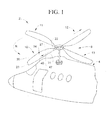
FIG. 1 is a partial perspective view of a helicopter including a rotor blade provided with an electromechanical rotary actuator in accordance with an exemplary embodiment; -
FIG. 2 is a plan view of the rotor blade ofFIG. 1 illustrating the electromechanical rotary actuator in accordance with an exemplary embodiment; -
FIG. 3 is an end view of the rotor blade ofFIG. 2 ; -
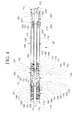
FIG. 4 is a plan view of the electromechanical rotary actuator in accordance with the exemplary embodiment; -
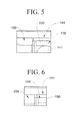
FIG. 5 is a detail view of a portion of the electromechanical rotary actuator in accordance with the exemplary embodiment; and -
FIG. 6 is a detail view of another portion of the electromechanical rotary actuator in accordance with the exemplary embodiment. - A detailed description of one or more embodiments of the disclosed apparatus and method are presented herein by way of exemplification and not limitation with reference to the Figures.
- With reference to
FIG. 1 , a rotary-wing aircraft, constructed in accordance with an exemplary embodiment, is indicated generally at 2. Rotary-wing aircraft 2 includes anairframe 4 and arotor system 8 including a plurality of rotor blades 10-13. As each rotor blade 10-13 is substantially similar, a detailed description will followreferencing rotor blade 10 with an understanding that the remaining rotor blades 11-13 contain similar structure.Rotor blade 10 includes a first orroot portion 22 that extends to a second ortip portion 23 through anairfoil portion 24 having first and secondopposing surfaces 27 and 28 (FIG. 3 ).Rotor blade 10 is further shown to include atrailing edge 30 and an opposing, leadingedge 31. As will be detailed more fully below,rotor blade 10 includes a rotorblade control system 40 including an electromechanicalrotary actuator 47 arranged withinairfoil portion 24. - As best shown in
FIG. 2 , rotorblade control system 40 includes acontroller 50 mounted withinairfoil portion 24.Controller 50 is operatively linked to a control system (not shown) arranged withinairframe 4 through awire harness 55.Controller 50 is also operatively linked to electromechanicalrotary actuator 47 through awire harness 59. Electromechanicalrotary actuator 47 is linked to anaxle 63. Axle 63 includes afirst end 65 that extends to asecond end 66 through anintermediate portion 67.First end 65 is operatively coupled to electromechanicalrotary actuator 47 whilesecond end 66 is supported by abearing 68. - In accordance with the exemplary embodiment shown, rotor
blade control system 40 includes a plurality of effectors 70-72 arranged withinairfoil portion 24. As will be discussed more fully below, effectors 70-72 are selectively deployed between first andsecond surfaces 27 and 28 (FIG. 1 ) in order to affect flight dynamics ofrotor blade 10. At this point it should be understood that each effector 70-72 is substantially similar such that reference will follow toFIG. 3 in describingeffector 70 with an understanding thateffectors effector 70 includes afirst end portion 80 that extends to asecond end portion 82 through anintermediate portion 83.First end portion 80 is coupled toaxle 63 whilesecond end portion 82 includes aflap 86.Flap 86 includes afirst flap portion 88 and asecond flap portion 89. Electromechanicalrotary actuator 47 rotateseffector 70 from a first or stowed position, such thatflap 86 is disposed withinrotor blade 10 to a second, deployed position, such thatflap 86 extends out of the outer periphery ofrotor blade 10. At this point it should be understood that the above description is provided for the sake of completeness and to enable a better understanding of one exemplary application of electromechanicalrotary actuator 47. - As best shown in
FIG. 4 , electromechanicalrotary actuator 47 includes ahousing 100 having afirst end 104 that extends to asecond end 105 through anintermediate portion 106 that defines a longitudinal axis of electromechanicalrotary actuator 47.Housing 100 also includes aninternal cavity 108 that supports various components ofelectromechanical actuator 47.First end 104 includes afirst end cap 110 andsecond end 105 includes asecond end cap 111.First end cap 110 includes an opening 112 andsecond end cap 111 includes aplug 113. Anelectric motor 114 is arranged withininternal cavity 108.Electric motor 114 takes the form of a brushless motor having astator 116 and arotor 117.Rotor 117 supports ashaft 120 having afirst shaft end 122 and an opposingsecond shaft end 123.Shaft 120 defines a central axis (not separately labeled) of electromechanicalrotary actuator 47. - A
coupler 129 is joined tofirst shaft end 122.Coupler 129 includes afirst coupler end 130 and asecond coupler end 131, anouter surface 132 and aninternal bore 133 that extends between first and second coupler ends 130 and 131. Anannular ring 134 extends aboutouter surface 132.First shaft end 122 extends intointernal bore 133 atfirst coupler end 130. A firstbearing assembly 138 rotatably supportsfirst shaft end 122.Bearing assembly 138 includes anouter race 139, andinner race 140 and a plurality ofbearing elements 141.First coupler end 130 extends into bearingassembly 138 withannular ring 133 abuttinginner race 140. Afirst bearing housing 144 extends aboutfirst bearing assembly 138. First bearinghousing 144 includes a raisedportion 145 that abutsouter race 139 andstator 114. - Electromechanical
rotary actuator 47 also includes adrive member 154 arranged withininternal cavity 108.Drive member 154 takes the form of a harmonic drive gear box having a gearedinput shaft 152 and anoutput shaft 155.Drive member 154 is configured to produce nearly substantially zero back lash between gearedinput shaft 152 andoutput shaft 155. Afirst spacer 160 is arranged betweendrive member 154 andfirst bearing assembly 138.First spacer 160 abuts drivemember 154 andouter race 139. Anoutput shaft member 170 is coupled tooutput shaft 155 ofdrive member 154.Output shaft member 170 includes afirst end section 172 that extends to asecond end section 176 through anintermediate section 177.First end section 172 includes aflange 179 and acavity 181 that receives gearedoutput shaft 155. - A
second bearing assembly 184 is positioned to supportoutput shaft member 170.Second bearing assembly 184 includes anouter race 186 and aninner race 187 that support a plurality of bearingelements 188.Inner race 187 is secured tointermediate section 177 ofoutput shaft member 170.Second bearing assembly 184 is surrounded by asecond bearing housing 191. Second bearinghousing 191 includes a raisedportion 192 that abutsouter race 186 ofsecond bearing assembly 184. Second bearinghousing 191 also abutsdrive member 154. The particular positioning and interaction ofoutput shaft member 170, first andsecond bearing housings first spacer 160 establishes a load path that is radially outward of the central axis of electromechanicalrotary actuator 47. That is, instead of external loads passing directly along the central axis, the arrangement ofoutput shaft member 170, first andsecond bearing housings first spacer 160 guides external forces along a load path that is radially outward of the central axis to reduce forces on, for example,electric motor 114 and drive member154. - In accordance with an exemplary embodiment, electromechanical
rotary actuator 47 includes apreload member 196 arranged adjacent tosecond bearing housing 191.Preload member 196 includes aspring 198 arranged within aspring housing 204.Spring 198 engages with a raisedportion 205 provided onspring housing 204. Aseal ring 209 is arranged betweenfirst end cap 110 andspring 198.Spring 198 is compressed betweenseal ring 209 andspring housing 204 to provide a preload force tooutput shaft member 170,drive member 154, andelectric motor 114 as well as additional components of electromechanicalrotary actuator 47. The preload or compressive axial force is applied along the longitudinal axis of electromechanicalrotary actuator 47. The application of the compressive axial force accommodates thermal expansion of electromechanicalrotary actuator 47 along the longitudinal axis. In this manner, electromechanicalrotary actuator 47 may be formed to have a compact form factor so as to be mountable in structure that does not possess an abundance of available internal space while also being able to withstand environmental changes including changes in temperature and acceleration. Accommodating thermal expansion in this manner allowsactuator 47 to be fabricated from various materials having different thermal expansion coefficients, and also allowsactuator 47 to operate in harsh temperature environments. Accordingly, changes in rates of thermal expansion of various ones of the internal components ofactuator 47 are absorbed by the preload. In this manner, the internal components will be maintainable within the overall envelope of the actuator. - Electromechanical
rotary actuator 47 also includes aresolver 220 operatively connected tosecond shaft end 123.Resolver 220 is configured to sense an angular position ofoutput shaft member 170 and provide feedback to an external controller (not shown).Resolver 220 includes aninner resolver section 221 connected tosecond shaft end 123 and anouter resolver section 222. Anend bearing assembly 225 is also coupled tosecond shaft end 123.End bearing assembly 225 includes anouter race 227 and aninner race 228 that retain a plurality of bearingelements 229.Inner race 228 is coupled tosecond shaft end 123 andouter race 227 is arranged within anend bearing housing 232 that extends betweenelectric motor 114 andresolver 220.End bearing housing 232 transmits external loads fromelectric motor 114 toouter resolver section 222 along an axis ofshaft 120. It should also be understood, thatend bearing assembly 225 is not subjected to the compressive axial force provided bypreload member 196. In addition, atensioning nut 235 is provided onsecond shaft end 123 adjacent tosecond end cap 111.Tensioning nut 235 aligns withplug 113. In this manner, plug 113 may be removed to provide access totensioning nut 235. In this manner, first and second end caps 110 and 111 are positioned to adjust the compressive axial force applied bypreload member 196. As such,preload member 196 may be adjusted to accommodate differing rates of thermal expansion of various ones of the internal components ofactuator 47. - At this point it should be understood that the particular arrangement of components in the electromechanical rotary acutuator establishes multiple load paths; a first load path that extends along a central axis that absorbs body forces due to the rotating component being subjected to high accelerations, and a second load path, radially offset from the central axis, that absorbs external loads. A preload in the first load path is established by adjusting
tensioning nut 235. The preload allowsactuator 47 to accommodate various rates of thermal expansion of the internal components. In this manner, the internal components are maintainable within an overall envelope ofactuator 47 regardless of operating/environmental conditions. Also, it should be understood that while described in connection with a rotor blade control system, the electromechanical rotary actuator may be employed to provide a gear reduction or increase for any number of systems desiring a compact system capable of operating in multiple environments and should not be considered as being limited to rotary aircraft or aircraft of any kind. - While the invention has been described with reference to an exemplary embodiment or embodiments, it will be understood by those skilled in the art that various changes may be made and equivalents may be substituted for elements thereof without departing from the scope of the invention. In addition, many modifications may be made to adapt a particular situation or material to the teachings of the invention without departing from the essential scope thereof. Therefore, it is intended that the invention not be limited to the particular embodiment disclosed as the best mode contemplated for carrying out this invention, but that the invention will include all embodiments falling within the scope of the claims.
Claims (15)
- An electromechanical rotary actuator (47) comprising:a housing (100) including a first end (104) that extends to a second end (105) through an intermediate portion (106) that defines a longitudinal axis, the housing defining an internal cavity (108);an electric motor (114) arranged within the internal cavity (108), the electric motor (114) including a stator (116) and a rotor (117), the rotor (117) surrounding a shaft (120) having a first shaft end (122) and a second shaft end (123);a drive member (154) arranged within the housing (100) along the longitudinal axis, the drive member (154) including an input shaft (152) operatively coupled to the first shaft end (122) and an output shaft (155);an output shaft member (170) coupled to the output shaft (155) of the drive member (154), the output shaft member (170) extending out from the first end (104) of the housing (100) and being configured and disposed to rotate about the longitudinal axis;at least one bearing assembly (138;184) supporting one of the output shaft (155) and the first shaft end (122); anda preload member (196) arranged within the housing (100) and configured to apply a compressive axial force to the at least one bearing (138;184), the drive member (154) and the electric motor (114), the preload member (196) accommodating thermal expansion of the electromechanical rotary actuator (47) along the longitudinal axis.
- The electromechanical rotary actuator according to claim 1, further comprising: a resolver (220) operatively coupled to the one of the input shaft (152) and the output shaft (155) of the drive member (154).
- The electromechanical rotary actuator according to claim 2, wherein the at least one bearing assembly includes a first bearing assembly (138) supporting the first shaft end (122) and a second bearing assembly (184) supporting the output shaft member (170), and an end bearing assembly (225) arranged to support the second shaft end (123), the first and second bearing assemblies (138,184) being subjected to the compressive axial force.
- The electromechanical rotary actuator according to claim 3, wherein the preload member (196) comprises a spring (198) arranged adjacent the second bearing assembly (184).
- The electromechanical rotary actuator according to claim 4, further comprising: a spring housing (204) extending about the spring (198) and abutting an outer race (186) of the second bearing assembly (184), the spring housing (204) being subjected to the compressive axial force.
- The electromechanical rotary actuator according to claim 5, further comprising an end cap (110) provided at the first end (104) of the housing (100), the end cap (110) including an opening (112) that receives the output shaft member (170).
- The electromechanical rotary actuator according to claim 6, further comprising: a seal ring (209) arranged between the end cap (110) and the spring (198), the seal ring (209) being subjected to the compressive axial force.
- The electromechanical rotary actuator according to any of claims 3 to 7, further comprising: a first bearing housing (144) extending about the first bearing assembly (138) and abutting the stator (116) of the electric motor (114), the first bearing housing (144) being subjected to the compressive axial force.
- The electromechanical rotary actuator according to any of claims 3 to 8, further comprising: a spacer (160) arranged between the first bearing assembly (138) and the drive member (154), the spacer (160) being subjected to the compressive axial force.
- The electromechanical rotary actuator according to any of claims 3 to 9, further comprising: a second bearing housing (191) extending about the second bearing assembly (184) and abutting the drive member (154), the second bearing housing (191) being subjected to the compressive axial force.
- The electromechanical rotary actuator according to any of claims 3 to 10, further comprising: an end bearing housing (232) extending about the end bearing assembly (225) and abutting the resolver (220), the end bearing housing (232) being subjected to the compressive axial force.
- The electromechanical rotary actuator according to any preceding claim, wherein the housing (100) is arranged within a rotor blade (11) of a rotary aircraft (2) and the output shaft (155) is coupled to a trailing edge effector.
- A method of forming an electromechanical rotary actuator (47), the method comprising:arranging an electric motor (114) including a stator (116), a rotor (117), and a shaft (120) having a first shaft end (122) and second shaft end (123) in a housing (100) that defines a longitudinal axis;positioning a drive member (154) having an input shaft (152) and an output shaft (155) in the housing (100);coupling the input shaft (152) to the first shaft end (122);coupling an output shaft member (170) to the output shaft (155) with a portion of the output shaft member (170) extending from the housing (100);supporting the first shaft end (122) with a first bearing assembly (138) and the output shaft member (170) with a second bearing assembly (184); andapplying a compressive axial force through a preload member (196) to the output shaft member (170), the drive member (154), the electric motor (114) and the first and second bearing assemblies (184,138) that accommodates thermal expansion of the electromechanical rotary actuator (47) along the longitudinal axis.
- The method of claim 13, further comprising: forming a load path that guides external loads applied at the output shaft member (170) radially outward of the drive member (154), and rotational loads of the first shaft end (122) through the drive member (154) and the output shaft member (170), wherein forming the load path optionally includes constructing a load path that possesses substantially zero back lash.
- The method of claim 13 or 14, further comprising: positioning a spring housing (204) between the preload member (196) and an outer race (186) of the second bearing assembly (184), and/or optionally further comprising: positioning a spacer (160) between the drive member (154) and an outer race (139) of the first bearing assembly (138), and/or optionally further comprising: positioning a bearing housing (191) between the drive member (154) and the second bearing assembly (184).
Applications Claiming Priority (1)
| Application Number | Priority Date | Filing Date | Title |
|---|---|---|---|
| US13/484,689 US9407121B2 (en) | 2012-05-31 | 2012-05-31 | Electromechanical rotary actuator and method |
Publications (3)
| Publication Number | Publication Date |
|---|---|
| EP2670029A2 true EP2670029A2 (en) | 2013-12-04 |
| EP2670029A3 EP2670029A3 (en) | 2016-11-16 |
| EP2670029B1 EP2670029B1 (en) | 2021-05-05 |
Family
ID=48446102
Family Applications (1)
| Application Number | Title | Priority Date | Filing Date |
|---|---|---|---|
| EP13167451.7A Active EP2670029B1 (en) | 2012-05-31 | 2013-05-13 | Electromechanical rotary actuator and method |
Country Status (3)
| Country | Link |
|---|---|
| US (1) | US9407121B2 (en) |
| EP (1) | EP2670029B1 (en) |
| RU (1) | RU2631734C2 (en) |
Families Citing this family (4)
| Publication number | Priority date | Publication date | Assignee | Title |
|---|---|---|---|---|
| US20160229525A1 (en) * | 2014-09-10 | 2016-08-11 | Hamilton Sundstrand Corporation | Electromechanical rotary actuator |
| US10759515B2 (en) | 2014-09-10 | 2020-09-01 | Hamilton Sunstrand Corporation | Electromechanical hinge-line rotary actuator |
| US9739362B2 (en) | 2015-03-30 | 2017-08-22 | Hamilton Sundstrand Corporation | Method for condensation reduction in linear electromechanical actuators |
| RU2702869C2 (en) * | 2017-12-14 | 2019-10-11 | Акционерное общество "Диаконт" | Electromechanical drive for controlling active shutter of helicopter rotor blade |
Family Cites Families (16)
| Publication number | Priority date | Publication date | Assignee | Title |
|---|---|---|---|---|
| US3495108A (en) * | 1968-03-19 | 1970-02-10 | Us Navy | Self-contained servomechanism |
| JPS5919809A (en) * | 1982-07-27 | 1984-02-01 | Fanuc Ltd | Coupling structure of servomotor and rotation detector |
| US5205147A (en) | 1989-05-12 | 1993-04-27 | Fuji Electric Co., Ltd. | Pre-loaded actuator using piezoelectric element |
| US5041748A (en) | 1989-10-16 | 1991-08-20 | Sundstrand Corporation | Lightweight, direct drive electromechanical actuator |
| JPH1155902A (en) * | 1997-07-30 | 1999-02-26 | Oriental Motor Co Ltd | Structure of sensor built-in motor |
| JP2907335B1 (en) | 1998-03-24 | 1999-06-21 | 株式会社コミュータヘリコプタ先進技術研究所 | Flap drive for rotor blades |
| US6192684B1 (en) | 1999-03-18 | 2001-02-27 | Swales Aerospace | Mechanical actuator assembly |
| US6422259B1 (en) | 2000-11-03 | 2002-07-23 | Delphi Technologies, Inc. | Apparatus and method for actuator stroke and spring preload setting |
| JP3988519B2 (en) * | 2001-06-20 | 2007-10-10 | 株式会社ジェイテクト | Electric power steering device |
| US7573011B2 (en) | 2005-09-08 | 2009-08-11 | Flextronics Ap, Llc | Zoom module using actuator and lead screw with translating operation |
| US8915710B2 (en) * | 2005-12-09 | 2014-12-23 | Sikorsky Aircraft Corporation | Brushless direct current (BLDC) motor based linear or rotary actuator for helicopter rotor control |
| US7677868B2 (en) * | 2006-12-07 | 2010-03-16 | Sikorsky Aircraft Corporation | Self-lubricated actuator for on-blade rotor control |
| US7762770B2 (en) | 2006-12-14 | 2010-07-27 | Sikorsky Aircraft Corporation | Hybrid actuator for helicopter rotor blade control flaps |
| US7765877B2 (en) | 2007-11-30 | 2010-08-03 | Caterpillar Inc | System for preloading piezoelectric actuators and method |
| EP2341259B1 (en) | 2010-01-05 | 2019-03-13 | Sikorsky Aircraft Corporation | Mechanical system for high acceleration environments |
| RU2442721C1 (en) * | 2010-06-09 | 2012-02-20 | Российская Федерация, От Имени Которой Выступает Министерство Промышленности И Торговли Российской Федерации | Design of electro-mechanical drive of airplane airfoil |
-
2012
- 2012-05-31 US US13/484,689 patent/US9407121B2/en active Active
-
2013
- 2013-05-13 EP EP13167451.7A patent/EP2670029B1/en active Active
- 2013-05-27 RU RU2013123897A patent/RU2631734C2/en active
Non-Patent Citations (1)
| Title |
|---|
| None |
Also Published As
| Publication number | Publication date |
|---|---|
| EP2670029B1 (en) | 2021-05-05 |
| US20130320782A1 (en) | 2013-12-05 |
| RU2013123897A (en) | 2014-12-10 |
| EP2670029A3 (en) | 2016-11-16 |
| RU2631734C2 (en) | 2017-09-26 |
| US9407121B2 (en) | 2016-08-02 |
Similar Documents
| Publication | Publication Date | Title |
|---|---|---|
| US11414174B1 (en) | Electrically driven blade control for rotorcraft | |
| CN105691592B (en) | Electromechanical hinge line rotary actuator | |
| EP3032725B1 (en) | Multi-slice rotary electromechanical actuator | |
| EP3312475B1 (en) | Compound harmonic drive assembly | |
| EP1794051B1 (en) | Compact pylon actuation system for tiltrotor aircraft | |
| EP3279512B1 (en) | Joined flex spline for compound harmonic drive | |
| EP2670029B1 (en) | Electromechanical rotary actuator and method | |
| CN112805475B (en) | Turbine engine comprising a rotor supporting pitch blades | |
| EP2557033A2 (en) | Modular counter rotating propeller system | |
| US20200332872A1 (en) | Inverted compound harmonic drive | |
| US11958595B2 (en) | Actuator for aviation applications | |
| US11391356B2 (en) | Hybrid gear construction | |
| EP3137377B1 (en) | Radially compliant quill shaft | |
| US9531238B2 (en) | Modular actuation device for an aerodynamic control surface of a missile | |
| EP3539868B1 (en) | Flexible coupling for standpipe assembly | |
| EP2487108B1 (en) | Modular integrated device for rotor blade control | |
| EP2873612B1 (en) | Counter-rotating rotor system with fairing | |
| KR102457195B1 (en) | Single propeller assembly for unmanned aerial vehicle | |
| EP4177160A1 (en) | Attachment for rotary actuator to wing |
Legal Events
| Date | Code | Title | Description |
|---|---|---|---|
| PUAI | Public reference made under article 153(3) epc to a published international application that has entered the european phase |
Free format text: ORIGINAL CODE: 0009012 |
|
| AK | Designated contracting states |
Kind code of ref document: A2 Designated state(s): AL AT BE BG CH CY CZ DE DK EE ES FI FR GB GR HR HU IE IS IT LI LT LU LV MC MK MT NL NO PL PT RO RS SE SI SK SM TR |
|
| AX | Request for extension of the european patent |
Extension state: BA ME |
|
| RIN1 | Information on inventor provided before grant (corrected) |
Inventor name: JONSSON, ULF J. Inventor name: WAKE, BRIAN E. Inventor name: BREWER, PAUL Inventor name: KUCZEK, ANDRZEJ ERNEST Inventor name: CHAUDHRY, ZAFFIR A. Inventor name: MATALANIS CLAUDE G. |
|
| PUAL | Search report despatched |
Free format text: ORIGINAL CODE: 0009013 |
|
| AK | Designated contracting states |
Kind code of ref document: A3 Designated state(s): AL AT BE BG CH CY CZ DE DK EE ES FI FR GB GR HR HU IE IS IT LI LT LU LV MC MK MT NL NO PL PT RO RS SE SI SK SM TR |
|
| AX | Request for extension of the european patent |
Extension state: BA ME |
|
| RIC1 | Information provided on ipc code assigned before grant |
Ipc: H02K 7/14 20060101AFI20161012BHEP Ipc: B64C 27/615 20060101ALI20161012BHEP Ipc: H02K 5/173 20060101ALI20161012BHEP Ipc: B64C 27/72 20060101ALN20161012BHEP |
|
| STAA | Information on the status of an ep patent application or granted ep patent |
Free format text: STATUS: REQUEST FOR EXAMINATION WAS MADE |
|
| 17P | Request for examination filed |
Effective date: 20170516 |
|
| RBV | Designated contracting states (corrected) |
Designated state(s): AL AT BE BG CH CY CZ DE DK EE ES FI FR GB GR HR HU IE IS IT LI LT LU LV MC MK MT NL NO PL PT RO RS SE SI SK SM TR |
|
| GRAP | Despatch of communication of intention to grant a patent |
Free format text: ORIGINAL CODE: EPIDOSNIGR1 |
|
| STAA | Information on the status of an ep patent application or granted ep patent |
Free format text: STATUS: GRANT OF PATENT IS INTENDED |
|
| RIC1 | Information provided on ipc code assigned before grant |
Ipc: H02K 7/14 20060101AFI20200319BHEP Ipc: B64C 27/615 20060101ALI20200319BHEP Ipc: H02K 5/173 20060101ALI20200319BHEP Ipc: B64C 27/72 20060101ALN20200319BHEP |
|
| INTG | Intention to grant announced |
Effective date: 20200401 |
|
| RAP1 | Party data changed (applicant data changed or rights of an application transferred) |
Owner name: HAMILTON SUNDSTRAND CORPORATION Owner name: CLAVERHAM LIMITED |
|
| GRAJ | Information related to disapproval of communication of intention to grant by the applicant or resumption of examination proceedings by the epo deleted |
Free format text: ORIGINAL CODE: EPIDOSDIGR1 |
|
| STAA | Information on the status of an ep patent application or granted ep patent |
Free format text: STATUS: REQUEST FOR EXAMINATION WAS MADE |
|
| INTC | Intention to grant announced (deleted) | ||
| GRAP | Despatch of communication of intention to grant a patent |
Free format text: ORIGINAL CODE: EPIDOSNIGR1 |
|
| STAA | Information on the status of an ep patent application or granted ep patent |
Free format text: STATUS: GRANT OF PATENT IS INTENDED |
|
| RIC1 | Information provided on ipc code assigned before grant |
Ipc: B64C 27/615 20060101ALI20200901BHEP Ipc: H02K 7/14 20060101AFI20200901BHEP Ipc: B64C 27/72 20060101ALN20200901BHEP Ipc: H02K 5/173 20060101ALI20200901BHEP |
|
| RIC1 | Information provided on ipc code assigned before grant |
Ipc: H02K 7/14 20060101AFI20200916BHEP Ipc: B64C 27/615 20060101ALI20200916BHEP Ipc: H02K 5/173 20060101ALI20200916BHEP Ipc: B64C 27/72 20060101ALN20200916BHEP |
|
| INTG | Intention to grant announced |
Effective date: 20201006 |
|
| GRAS | Grant fee paid |
Free format text: ORIGINAL CODE: EPIDOSNIGR3 |
|
| STAA | Information on the status of an ep patent application or granted ep patent |
Free format text: STATUS: GRANT OF PATENT IS INTENDED |
|
| RAP1 | Party data changed (applicant data changed or rights of an application transferred) |
Owner name: HAMILTON SUNDSTRAND CORPORATION Owner name: CLAVERHAM LIMITED |
|
| GRAA | (expected) grant |
Free format text: ORIGINAL CODE: 0009210 |
|
| STAA | Information on the status of an ep patent application or granted ep patent |
Free format text: STATUS: THE PATENT HAS BEEN GRANTED |
|
| AK | Designated contracting states |
Kind code of ref document: B1 Designated state(s): AL AT BE BG CH CY CZ DE DK EE ES FI FR GB GR HR HU IE IS IT LI LT LU LV MC MK MT NL NO PL PT RO RS SE SI SK SM TR |
|
| REG | Reference to a national code |
Ref country code: GB Ref legal event code: FG4D |
|
| REG | Reference to a national code |
Ref country code: CH Ref legal event code: EP |
|
| REG | Reference to a national code |
Ref country code: AT Ref legal event code: REF Ref document number: 1391066 Country of ref document: AT Kind code of ref document: T Effective date: 20210515 |
|
| REG | Reference to a national code |
Ref country code: DE Ref legal event code: R096 Ref document number: 602013077281 Country of ref document: DE |
|
| REG | Reference to a national code |
Ref country code: IE Ref legal event code: FG4D |
|
| REG | Reference to a national code |
Ref country code: LT Ref legal event code: MG9D |
|
| REG | Reference to a national code |
Ref country code: AT Ref legal event code: MK05 Ref document number: 1391066 Country of ref document: AT Kind code of ref document: T Effective date: 20210505 |
|
| PG25 | Lapsed in a contracting state [announced via postgrant information from national office to epo] |
Ref country code: HR Free format text: LAPSE BECAUSE OF FAILURE TO SUBMIT A TRANSLATION OF THE DESCRIPTION OR TO PAY THE FEE WITHIN THE PRESCRIBED TIME-LIMIT Effective date: 20210505 Ref country code: BG Free format text: LAPSE BECAUSE OF FAILURE TO SUBMIT A TRANSLATION OF THE DESCRIPTION OR TO PAY THE FEE WITHIN THE PRESCRIBED TIME-LIMIT Effective date: 20210805 Ref country code: AT Free format text: LAPSE BECAUSE OF FAILURE TO SUBMIT A TRANSLATION OF THE DESCRIPTION OR TO PAY THE FEE WITHIN THE PRESCRIBED TIME-LIMIT Effective date: 20210505 Ref country code: LT Free format text: LAPSE BECAUSE OF FAILURE TO SUBMIT A TRANSLATION OF THE DESCRIPTION OR TO PAY THE FEE WITHIN THE PRESCRIBED TIME-LIMIT Effective date: 20210505 Ref country code: FI Free format text: LAPSE BECAUSE OF FAILURE TO SUBMIT A TRANSLATION OF THE DESCRIPTION OR TO PAY THE FEE WITHIN THE PRESCRIBED TIME-LIMIT Effective date: 20210505 |
|
| PG25 | Lapsed in a contracting state [announced via postgrant information from national office to epo] |
Ref country code: NO Free format text: LAPSE BECAUSE OF FAILURE TO SUBMIT A TRANSLATION OF THE DESCRIPTION OR TO PAY THE FEE WITHIN THE PRESCRIBED TIME-LIMIT Effective date: 20210805 Ref country code: PT Free format text: LAPSE BECAUSE OF FAILURE TO SUBMIT A TRANSLATION OF THE DESCRIPTION OR TO PAY THE FEE WITHIN THE PRESCRIBED TIME-LIMIT Effective date: 20210906 Ref country code: PL Free format text: LAPSE BECAUSE OF FAILURE TO SUBMIT A TRANSLATION OF THE DESCRIPTION OR TO PAY THE FEE WITHIN THE PRESCRIBED TIME-LIMIT Effective date: 20210505 Ref country code: ES Free format text: LAPSE BECAUSE OF FAILURE TO SUBMIT A TRANSLATION OF THE DESCRIPTION OR TO PAY THE FEE WITHIN THE PRESCRIBED TIME-LIMIT Effective date: 20210505 Ref country code: IS Free format text: LAPSE BECAUSE OF FAILURE TO SUBMIT A TRANSLATION OF THE DESCRIPTION OR TO PAY THE FEE WITHIN THE PRESCRIBED TIME-LIMIT Effective date: 20210905 Ref country code: LV Free format text: LAPSE BECAUSE OF FAILURE TO SUBMIT A TRANSLATION OF THE DESCRIPTION OR TO PAY THE FEE WITHIN THE PRESCRIBED TIME-LIMIT Effective date: 20210505 Ref country code: GR Free format text: LAPSE BECAUSE OF FAILURE TO SUBMIT A TRANSLATION OF THE DESCRIPTION OR TO PAY THE FEE WITHIN THE PRESCRIBED TIME-LIMIT Effective date: 20210806 Ref country code: SE Free format text: LAPSE BECAUSE OF FAILURE TO SUBMIT A TRANSLATION OF THE DESCRIPTION OR TO PAY THE FEE WITHIN THE PRESCRIBED TIME-LIMIT Effective date: 20210505 Ref country code: RS Free format text: LAPSE BECAUSE OF FAILURE TO SUBMIT A TRANSLATION OF THE DESCRIPTION OR TO PAY THE FEE WITHIN THE PRESCRIBED TIME-LIMIT Effective date: 20210505 |
|
| REG | Reference to a national code |
Ref country code: NL Ref legal event code: MP Effective date: 20210505 |
|
| REG | Reference to a national code |
Ref country code: CH Ref legal event code: PL |
|
| PG25 | Lapsed in a contracting state [announced via postgrant information from national office to epo] |
Ref country code: NL Free format text: LAPSE BECAUSE OF FAILURE TO SUBMIT A TRANSLATION OF THE DESCRIPTION OR TO PAY THE FEE WITHIN THE PRESCRIBED TIME-LIMIT Effective date: 20210505 |
|
| PG25 | Lapsed in a contracting state [announced via postgrant information from national office to epo] |
Ref country code: SM Free format text: LAPSE BECAUSE OF FAILURE TO SUBMIT A TRANSLATION OF THE DESCRIPTION OR TO PAY THE FEE WITHIN THE PRESCRIBED TIME-LIMIT Effective date: 20210505 Ref country code: SK Free format text: LAPSE BECAUSE OF FAILURE TO SUBMIT A TRANSLATION OF THE DESCRIPTION OR TO PAY THE FEE WITHIN THE PRESCRIBED TIME-LIMIT Effective date: 20210505 Ref country code: EE Free format text: LAPSE BECAUSE OF FAILURE TO SUBMIT A TRANSLATION OF THE DESCRIPTION OR TO PAY THE FEE WITHIN THE PRESCRIBED TIME-LIMIT Effective date: 20210505 Ref country code: CZ Free format text: LAPSE BECAUSE OF FAILURE TO SUBMIT A TRANSLATION OF THE DESCRIPTION OR TO PAY THE FEE WITHIN THE PRESCRIBED TIME-LIMIT Effective date: 20210505 Ref country code: DK Free format text: LAPSE BECAUSE OF FAILURE TO SUBMIT A TRANSLATION OF THE DESCRIPTION OR TO PAY THE FEE WITHIN THE PRESCRIBED TIME-LIMIT Effective date: 20210505 Ref country code: RO Free format text: LAPSE BECAUSE OF FAILURE TO SUBMIT A TRANSLATION OF THE DESCRIPTION OR TO PAY THE FEE WITHIN THE PRESCRIBED TIME-LIMIT Effective date: 20210505 Ref country code: CH Free format text: LAPSE BECAUSE OF NON-PAYMENT OF DUE FEES Effective date: 20210531 Ref country code: LI Free format text: LAPSE BECAUSE OF NON-PAYMENT OF DUE FEES Effective date: 20210531 Ref country code: LU Free format text: LAPSE BECAUSE OF NON-PAYMENT OF DUE FEES Effective date: 20210513 |
|
| REG | Reference to a national code |
Ref country code: DE Ref legal event code: R097 Ref document number: 602013077281 Country of ref document: DE |
|
| REG | Reference to a national code |
Ref country code: BE Ref legal event code: MM Effective date: 20210531 |
|
| PLBE | No opposition filed within time limit |
Free format text: ORIGINAL CODE: 0009261 |
|
| STAA | Information on the status of an ep patent application or granted ep patent |
Free format text: STATUS: NO OPPOSITION FILED WITHIN TIME LIMIT |
|
| PG25 | Lapsed in a contracting state [announced via postgrant information from national office to epo] |
Ref country code: MC Free format text: LAPSE BECAUSE OF FAILURE TO SUBMIT A TRANSLATION OF THE DESCRIPTION OR TO PAY THE FEE WITHIN THE PRESCRIBED TIME-LIMIT Effective date: 20210505 |
|
| 26N | No opposition filed |
Effective date: 20220208 |
|
| PG25 | Lapsed in a contracting state [announced via postgrant information from national office to epo] |
Ref country code: IE Free format text: LAPSE BECAUSE OF NON-PAYMENT OF DUE FEES Effective date: 20210513 |
|
| PG25 | Lapsed in a contracting state [announced via postgrant information from national office to epo] |
Ref country code: IS Free format text: LAPSE BECAUSE OF FAILURE TO SUBMIT A TRANSLATION OF THE DESCRIPTION OR TO PAY THE FEE WITHIN THE PRESCRIBED TIME-LIMIT Effective date: 20210905 Ref country code: AL Free format text: LAPSE BECAUSE OF FAILURE TO SUBMIT A TRANSLATION OF THE DESCRIPTION OR TO PAY THE FEE WITHIN THE PRESCRIBED TIME-LIMIT Effective date: 20210505 |
|
| PG25 | Lapsed in a contracting state [announced via postgrant information from national office to epo] |
Ref country code: IT Free format text: LAPSE BECAUSE OF FAILURE TO SUBMIT A TRANSLATION OF THE DESCRIPTION OR TO PAY THE FEE WITHIN THE PRESCRIBED TIME-LIMIT Effective date: 20210505 Ref country code: BE Free format text: LAPSE BECAUSE OF NON-PAYMENT OF DUE FEES Effective date: 20210531 |
|
| PG25 | Lapsed in a contracting state [announced via postgrant information from national office to epo] |
Ref country code: HU Free format text: LAPSE BECAUSE OF FAILURE TO SUBMIT A TRANSLATION OF THE DESCRIPTION OR TO PAY THE FEE WITHIN THE PRESCRIBED TIME-LIMIT; INVALID AB INITIO Effective date: 20130513 |
|
| PG25 | Lapsed in a contracting state [announced via postgrant information from national office to epo] |
Ref country code: CY Free format text: LAPSE BECAUSE OF FAILURE TO SUBMIT A TRANSLATION OF THE DESCRIPTION OR TO PAY THE FEE WITHIN THE PRESCRIBED TIME-LIMIT Effective date: 20210505 |
|
| PGFP | Annual fee paid to national office [announced via postgrant information from national office to epo] |
Ref country code: FR Payment date: 20230420 Year of fee payment: 11 Ref country code: DE Payment date: 20230419 Year of fee payment: 11 |
|
| PGFP | Annual fee paid to national office [announced via postgrant information from national office to epo] |
Ref country code: GB Payment date: 20230420 Year of fee payment: 11 |
|
| PG25 | Lapsed in a contracting state [announced via postgrant information from national office to epo] |
Ref country code: MK Free format text: LAPSE BECAUSE OF FAILURE TO SUBMIT A TRANSLATION OF THE DESCRIPTION OR TO PAY THE FEE WITHIN THE PRESCRIBED TIME-LIMIT Effective date: 20210505 |