EP2669980A1 - Fuel cell power generation system, and method for control of fuel cell power generation system - Google Patents
Fuel cell power generation system, and method for control of fuel cell power generation system Download PDFInfo
- Publication number
- EP2669980A1 EP2669980A1 EP12740026.5A EP12740026A EP2669980A1 EP 2669980 A1 EP2669980 A1 EP 2669980A1 EP 12740026 A EP12740026 A EP 12740026A EP 2669980 A1 EP2669980 A1 EP 2669980A1
- Authority
- EP
- European Patent Office
- Prior art keywords
- fuel cell
- gas
- oxidation
- temperature
- fuel
- Prior art date
- Legal status (The legal status is an assumption and is not a legal conclusion. Google has not performed a legal analysis and makes no representation as to the accuracy of the status listed.)
- Withdrawn
Links
Images


Classifications
-
- H—ELECTRICITY
- H01—ELECTRIC ELEMENTS
- H01M—PROCESSES OR MEANS, e.g. BATTERIES, FOR THE DIRECT CONVERSION OF CHEMICAL ENERGY INTO ELECTRICAL ENERGY
- H01M8/00—Fuel cells; Manufacture thereof
- H01M8/04—Auxiliary arrangements, e.g. for control of pressure or for circulation of fluids
- H01M8/04007—Auxiliary arrangements, e.g. for control of pressure or for circulation of fluids related to heat exchange
- H01M8/04067—Heat exchange or temperature measuring elements, thermal insulation, e.g. heat pipes, heat pumps, fins
-
- H—ELECTRICITY
- H01—ELECTRIC ELEMENTS
- H01M—PROCESSES OR MEANS, e.g. BATTERIES, FOR THE DIRECT CONVERSION OF CHEMICAL ENERGY INTO ELECTRICAL ENERGY
- H01M8/00—Fuel cells; Manufacture thereof
- H01M8/04—Auxiliary arrangements, e.g. for control of pressure or for circulation of fluids
- H01M8/04298—Processes for controlling fuel cells or fuel cell systems
- H01M8/04313—Processes for controlling fuel cells or fuel cell systems characterised by the detection or assessment of variables; characterised by the detection or assessment of failure or abnormal function
- H01M8/04537—Electric variables
- H01M8/04604—Power, energy, capacity or load
- H01M8/04619—Power, energy, capacity or load of fuel cell stacks
-
- H—ELECTRICITY
- H01—ELECTRIC ELEMENTS
- H01M—PROCESSES OR MEANS, e.g. BATTERIES, FOR THE DIRECT CONVERSION OF CHEMICAL ENERGY INTO ELECTRICAL ENERGY
- H01M8/00—Fuel cells; Manufacture thereof
- H01M8/04—Auxiliary arrangements, e.g. for control of pressure or for circulation of fluids
- H01M8/04298—Processes for controlling fuel cells or fuel cell systems
- H01M8/04694—Processes for controlling fuel cells or fuel cell systems characterised by variables to be controlled
- H01M8/04701—Temperature
- H01M8/04708—Temperature of fuel cell reactants
-
- H—ELECTRICITY
- H01—ELECTRIC ELEMENTS
- H01M—PROCESSES OR MEANS, e.g. BATTERIES, FOR THE DIRECT CONVERSION OF CHEMICAL ENERGY INTO ELECTRICAL ENERGY
- H01M8/00—Fuel cells; Manufacture thereof
- H01M8/04—Auxiliary arrangements, e.g. for control of pressure or for circulation of fluids
- H01M8/04298—Processes for controlling fuel cells or fuel cell systems
- H01M8/04694—Processes for controlling fuel cells or fuel cell systems characterised by variables to be controlled
- H01M8/04746—Pressure; Flow
- H01M8/04753—Pressure; Flow of fuel cell reactants
-
- H—ELECTRICITY
- H01—ELECTRIC ELEMENTS
- H01M—PROCESSES OR MEANS, e.g. BATTERIES, FOR THE DIRECT CONVERSION OF CHEMICAL ENERGY INTO ELECTRICAL ENERGY
- H01M8/00—Fuel cells; Manufacture thereof
- H01M8/04—Auxiliary arrangements, e.g. for control of pressure or for circulation of fluids
- H01M8/04298—Processes for controlling fuel cells or fuel cell systems
- H01M8/04694—Processes for controlling fuel cells or fuel cell systems characterised by variables to be controlled
- H01M8/04746—Pressure; Flow
- H01M8/04761—Pressure; Flow of fuel cell exhausts
-
- H—ELECTRICITY
- H01—ELECTRIC ELEMENTS
- H01M—PROCESSES OR MEANS, e.g. BATTERIES, FOR THE DIRECT CONVERSION OF CHEMICAL ENERGY INTO ELECTRICAL ENERGY
- H01M8/00—Fuel cells; Manufacture thereof
- H01M8/04—Auxiliary arrangements, e.g. for control of pressure or for circulation of fluids
- H01M8/04298—Processes for controlling fuel cells or fuel cell systems
- H01M8/04694—Processes for controlling fuel cells or fuel cell systems characterised by variables to be controlled
- H01M8/04746—Pressure; Flow
- H01M8/04776—Pressure; Flow at auxiliary devices, e.g. reformer, compressor, burner
-
- H—ELECTRICITY
- H01—ELECTRIC ELEMENTS
- H01M—PROCESSES OR MEANS, e.g. BATTERIES, FOR THE DIRECT CONVERSION OF CHEMICAL ENERGY INTO ELECTRICAL ENERGY
- H01M8/00—Fuel cells; Manufacture thereof
- H01M8/06—Combination of fuel cells with means for production of reactants or for treatment of residues
- H01M8/0606—Combination of fuel cells with means for production of reactants or for treatment of residues with means for production of gaseous reactants
- H01M8/0612—Combination of fuel cells with means for production of reactants or for treatment of residues with means for production of gaseous reactants from carbon-containing material
- H01M8/0618—Reforming processes, e.g. autothermal, partial oxidation or steam reforming
-
- H—ELECTRICITY
- H01—ELECTRIC ELEMENTS
- H01M—PROCESSES OR MEANS, e.g. BATTERIES, FOR THE DIRECT CONVERSION OF CHEMICAL ENERGY INTO ELECTRICAL ENERGY
- H01M8/00—Fuel cells; Manufacture thereof
- H01M8/04—Auxiliary arrangements, e.g. for control of pressure or for circulation of fluids
- H01M8/04007—Auxiliary arrangements, e.g. for control of pressure or for circulation of fluids related to heat exchange
- H01M8/04014—Heat exchange using gaseous fluids; Heat exchange by combustion of reactants
- H01M8/04022—Heating by combustion
-
- Y—GENERAL TAGGING OF NEW TECHNOLOGICAL DEVELOPMENTS; GENERAL TAGGING OF CROSS-SECTIONAL TECHNOLOGIES SPANNING OVER SEVERAL SECTIONS OF THE IPC; TECHNICAL SUBJECTS COVERED BY FORMER USPC CROSS-REFERENCE ART COLLECTIONS [XRACs] AND DIGESTS
- Y02—TECHNOLOGIES OR APPLICATIONS FOR MITIGATION OR ADAPTATION AGAINST CLIMATE CHANGE
- Y02E—REDUCTION OF GREENHOUSE GAS [GHG] EMISSIONS, RELATED TO ENERGY GENERATION, TRANSMISSION OR DISTRIBUTION
- Y02E60/00—Enabling technologies; Technologies with a potential or indirect contribution to GHG emissions mitigation
- Y02E60/30—Hydrogen technology
- Y02E60/50—Fuel cells
Abstract
Description
- The present invention relates to a fuel cell power generation system and to a method of controlling a fuel cell power generation system, which generate electric power while adjusting the temperature of a fuel cell in accordance with the required output.
- Japanese Patent Application Publication No.
2003-115315 2004-349214 - In
Patent Literature 1, the reaction temperature is limited to be within ±10°C, and the output of the fuel cell is therefore limited, making it impossible to widen the controllable range of power generation output. Suppose, for example, that a fuel cell power generation system is mounted on a vehicle to supply the vehicle's travelling energy. In this case, an electric power of several KW is required during a normal driving state which includes travelling in town and JC08 mode, and tens of KW or higher is needed during a high speed driving state at 100 Km/h or higher. However, the techniques described inPatent Literatures -
- Patent Literature 1: Japanese Patent Application Publication No.
2003-115315 - Patent Literature 2: Japanese Patent Application Publication No.
2004-349214 - As described above, it is difficult for the related techniques disclosed
Patent Literatures - The present invention has been made for solving a technical problem as described above, and an object thereof is to provide a fuel cell power generation system and a method of controlling a fuel cell power generation system, which are capable of changing the operating temperature of a fuel cell in accordance with the required power output.
- To achieve the above object, a fuel cell power generation system according to an embodiment of the present invention comprises: a fuel cell configured to generate electric power upon supply of oxidation gas and fuel gas; and a temperature adjustment unit configured to adjust the temperature of the oxidation gas to be supplied to an oxidation-gas inlet of the fuel cell. In a case where the required output of the fuel cell is high, the temperature adjustment unit is controlled to make the temperature of the oxidation gas to be supplied to the oxidation-gas inlet higher than that in a case where the required output is low. In this manner, in the case where the required output of the fuel cell is high, the operating temperature of the fuel cell is made higher than that in the case where the required output is low.
-
- [
Fig. 1] Fig. 1 is a block diagram showing the configuration of a fuel cell power generation system according to a first embodiment of the present invention. - [
Fig. 2] Fig. 2 is a characteristics chart showing the correlation between a power output ratio and the ratio of the amount of heat generation by combustion of a burner in the fuel cell power generation system according to the embodiment of the present invention. - [
Fig. 3] Fig. 3 is a characteristics chart showing the correlation between the power output ratio and system efficiency in the fuel cell power generation system according to the embodiment of the present invention. - [
Fig. 4] Fig. 4 is a characteristics chart showing the correlation between the power output ratio and an excess oxidation gas percentage ratio in the fuel cell power generation system according to the embodiment of the present invention. - [
Fig. 5] Fig. 5 is a flowchart showing the sequence of an output control process of the fuel cell power generation system according to the first embodiment of the present invention. - [
Fig. 6] Fig. 6 is a block diagram showing the configuration of a fuel cell power generation system according to a second embodiment of the present invention. - [
Fig. 7] Fig. 7 is a flowchart showing the sequence of an output control process of the fuel cell power generation system according to the second embodiment of the present invention. - [
Fig. 8] Fig. 8 is a block diagram showing the configuration of a fuel cell power generation system according to a third embodiment of the present invention. - [
Fig. 9] Fig. 9 is a flowchart showing the sequence of an output control process of the fuel cell power generation system according to the third embodiment of the present invention. - Hereinbelow, embodiments of the present invention will be described based on the drawings.
Fig. 1 is a block diagram showing the configuration of a fuel cellpower generation system 100 according to a first embodiment of the present invention. As shown inFig. 1 , the fuel cellpower generation system 100 includes: afuel cell 11 including acathode electrode 11a and ananode electrode 11b; a first air blower 12 (an oxidation-gas supply unit) which supplies air, as an example of oxidation gas, to thecathode electrode 11a; an air-heating heat exchanger 13 (heat exchange unit) which heats the air sent out by thefirst air blower 12; afirst fuel pump 14 which supplies a fuel such as hydrocarbon fuel to theanode electrode 11b of thefuel cell 11; and afuel reformer 15 which reforms the fuel sent out from thefirst fuel pump 14 through a fuel-gas flow path L1 and supplies the reformed fuel to theanode electrode 11b. - The fuel cell
power generation system 100 further includes: afuel circulating blower 17 which circulates fuel gas discharged from theanode electrode 11b into thefuel reformer 15; a reformer-heating heat exchanger 16 (reformer heating unit) to which exhaust gas discharged from thecathode electrode 11 a is introduced through an exhaust-gas flow path L2 and which heats thefuel reformer 15 by using the introduced exhaust gas; a fuel-flow-path pressure adjustment valve 18 (second pressure adjustment valve) which is provided between the output opening of thefuel circulating blower 17 and the exhaust-gas flow path L2 and introduces a part of the fuel gas discharged from theanode electrode 11b into the exhaust-gas flow path L2; and an exhaust-flow-path pressure adjustment valve 19 (first pressure adjustment valve) which is provided to the exhaust-gas flow path L2 near the reformer-heating heat exchanger 16 and discharges, to the outside, a part of the exhaust gas to be introduced into the reformer-heating heat exchanger 16 through the exhaust-gas flow path L2. - The fuel cell
power generation system 100 also includes a combustion burner 23 (temperature adjustment unit, temperature adjustment means) which performs combustion using air supplied by asecond air blower 21 and fuel supplied by asecond fuel pump 22 and introduces heated air into an oxidation-gas inlet of thecathode electrode 11 a. - The
fuel cell 11 is a solid oxide fuel cell (SOFC), for example, and generates electric power by using the reformed fuel supplied to theanode electrode 11b and the air supplied to thecathode electrode 11 a and supplies the electric power to equipment such as a motor that needs electric power. - The
fuel reformer 15 is configured to be heated by heat supplied by the reformer-heating heat exchanger 16 and reform fuel supplied by thefirst fuel pump 14 though a catalytic reaction, and supply the reformed fuel, i.e. reformed gas containing hydrogen gas to theanode electrode 11b of thefuel cell 11. - Meanwhile, the
first air blower 12, thefirst fuel pump 14, thesecond air blower 21, thesecond fuel pump 22, the exhaust-flow-pathpressure adjustment valve 19, and the fuel-flow-pathpressure adjustment valve 18 are each connected to a control unit 31 (control means). Thiscontrol unit 31 is a device formed, for example, of a CPU, a RAM, a ROM, various controllers, and so on and, as will be described later, controls each component by sending a control signal to the component in accordance with the required power output. - Next, operation of the fuel cell
power generation system 100 according to this embodiment will be described. The fuel cellpower generation system 100 according to this embodiment drives thecombustion burner 23 to supply heated air to thefuel cell 11 and thus change the operating temperature of thefuel cell 11, so as to handle changes in output power. Here, it is preferable to change the temperature within a range of ±50°C from the operating temperature in a normal state. As an example, this embodiment will describe an instance where the operating temperature of thefuel cell 11 in the normal state is 700°C, and the operating temperature is changed within a range of ±50°C from this temperature, i.e. within a range of 650°C to 750°C. Meanwhile, thefuel reformer 15 operates at a temperature of approximately 700°C. - First, the
first air blower 12 is driven to send out air from thefirst air blower 12. The air sent out by thefirst air blower 12 passes through a low temperature side of the air-heating heat exchanger 13, i.e. a side where heat absorption occurs, and is then introduced into the oxidation-gas inlet of thecathode electrode 11 a. Here, hot exhaust gas discharged from the reformer-heating heat exchanger 16 is introduced into a high temperature side of the air-heating heat exchanger 13, i.e. a side where heat dissipation occurs. Thus, the air sent out by thefirst air blower 12 is heated by the heat of the exhaust gas to a temperature lower than the temperature of thefuel cell 11 by 200°C to 300°C, and is then introduced into the oxidation-gas inlet of thecathode electrode 11 a. Note that the oxidation gas is not limited to air, and a gas containing oxygen can be used instead. - Moreover, the
second air blower 21 and thesecond fuel pump 22 are driven and fuel is combusted in thecombustion burner 23 to send out heated air from thecombustion burner 23. This heated air is mixed with air sent out by thefirst air blower 12 and is introduced into the oxidation-gas inlet of thecathode electrode 11 a. Here, the amount of the air supplied by thesecond air blower 21 and the amount of the fuel supplied by thesecond fuel pump 22 are adjusted as appropriate. In this way, air can be supplied into the oxidation-gas inlet of thecathode electrode 11a at a desired temperature in a desired amount. - Thus, by controlling the amount and temperature of the air to be sent out by the
combustion burner 23 under the control of thecontrol unit 31, it is possible to adjust the amount and temperature of the air to be supplied into the fuel inlet of thecathode electrode 11 a. - Next, the correlation between the operating temperature and the power generation output of the
fuel cell 11 will be described. First, the description will be given of a case of not driving thecombustion burner 23. - The temperature of air to be introduced into the oxidation-gas inlet of the
cathode electrode 11 a is a temperature lower than the normal operating temperature of the fuel cell 11 (650°C to 750°C) by 200°C to 300°C, for example. Hence, the air introduced in thecathode electrode 11a is heated by thermal energy produced during power generation of thefuel cell 11 to approximately the same temperature as the temperature of thefuel cell 11 and discharged through the outlet of thecathode electrode 11a. Thus, the larger the difference between the operating temperature of thefuel cell 11 and the temperature of the introduced air, the larger the amount of heat that moves from thefuel cell 11 to the air. - Moreover, increase in the power output of the
fuel cell 11 leads to increase in the amount of heat dissipation at thefuel cell 11. Then, if the amount of heat dissipation increases to or exceeds the amount of heat transmittable to air within thefuel cell 11, the operating temperature of thefuel cell 11 rises and exceeds to its normal temperature. For this reason, the number of revolutions of thefirst air blower 12 needs to be controlled to increase the amount of air to be introduced into the oxidation-gas inlet. That is, the amount of air is increased so that the amount of heat transmittable from thefuel cell 11 to air can be increased, thereby lowering the operating temperature of thefuel cell 11 to its normal temperature. - Next, the description will be given of a case of driving the
combustion burner 23 to mix heated air sent out by thecombustion burner 23 into air sent out by thefirst air blower 12 and introduce the mixed air into the oxidation-gas inlet, while appropriately adjusting the temperature and flow rate of thecombustion burner 23 to change the operating temperature of thefuel cell 11. -
Fig. 2 is a characteristics chart showing the correlation between the output power of thefuel cell 11 and the amount of heat generation by the fuel in thecombustion burner 23. A curve P1 inFig. 2 shows a case where the operating temperature of thefuel cell 11 is 650°C, while a curve P2 shows a case where the operating temperature of thefuel cell 11 is 750°C.Fig. 2 shows the correlation between the output ratio of electric power and the ratio of the amount of heat generation by the fuel in the burner, in the case where the output power during the maximum output operation with the operating temperature of thefuel cell 11 being 750°C is set to "5," and the amount of heat generation by the fuel in the burner in that state is set to "1." - As shown by the curve P1 in
Fig. 2 , in the case where the operating temperature of thefuel cell 11 is 650°C, the ratio of the amount of heat generation by the fuel in the burner abruptly increases as the power output ratio increases from "1," and the ratio of the amount of heat generation by the fuel in the burner reaches "1.4" when the power output ratio is "2.4." In contrast, as shown by the curve P2, in the case where the operating temperature of thefuel cell 11 is 750°C, the ratio of the amount of heat generation by the fuel in the burner is approximately "0.2" when the power output ratio is "2.4," and the ratio of the amount of heat generation by the fuel in the burner then linearly increases as the output ratio increases. - Here, in a comparison between the curve P1 and the curve P2 shown in
Fig. 2 at a power output ratio of "2.4," for example, the amount of heat generation of thecombustion burner 23 is greater and the amount of fuel supplied to thecombustion burner 23 is therefore greater in the case where the operating temperature of the fuel cell is low. This is because under a condition where the operating temperature of thefuel cell 11 is lower, the power generation efficiency is lower, so that the amount of heat dissipation increases accordingly, which in turn results in a need for introduction of more air and increases the necessary amount of fuel for heating this air. - Moreover,
Fig. 3 shows the correlation between system efficiency and the output power in the case where the amount of introduced air and the amount of fuel in thecombustion burner 23 are changed in accordance with changes in the output power. InFig. 3 , a curve P3 shows a case where the operating temperature of thefuel cell 11 is 650°C, while a curve P4 shows a case where the operating temperature of thefuel cell 11 is 750°C. In this case, the system efficiency is calculated from an equation (1) below. -

fuel cell 11 at a low temperature, e.g. 650°C, it is necessary to install alarge fuel cell 11 in advance so as to be capable of handling the maximum output. For example, in the case of thefuel cell 11 having performance shown inFig. 3 , the output ratio reaches a peak output approximately at "2.5," and the output cannot be any larger. Thus, if an output ratio of, for example, "5" is to be achieved, the size of thefuel cell 11 needs to be about two times larger. This case, however, causes a problem that the cost of thefuel cell 11 becomes about two times higher and also that the power generation efficiency becomes low. - Meanwhile, in the case where the
fuel cell 11 is to be operated at a high temperature, e.g. 750°C, the efficiency of thefuel cell 11 is high, thereby making it possible to cover a wider power generation range than the case where thefuel cell 11 is operated at a lower temperature of 650°C, for example. However, there is a disadvantage that thefuel cell 11 needs to be maintained at a high temperature, and it is therefore necessary to use many materials to maintain the durability and to use costly materials, which in turn leads to problems of increased size and cost of thefuel cell 11. - In this regard, in this embodiment, air heated by the
combustion burner 23 is introduced into the oxidation-gas inlet of thecathode electrode 11 a to change the operating temperature of thefuel cell 11, so as to solve the above problems. - In the case of using an SOFC power generation system as a power supply for driving a vehicle, an electric power of a relatively low output (several KW) is assumed for electric power required during a normal driving state such as travelling in town or JC08 mode. On the other hand, in the case of driving at a speed of 80 Km/h or higher for several hours, an electric power of a relatively high output (tens of KW) is required. The
fuel cell 11 capable of actively changing the operating temperature is effective in a use condition as above. That is, in generation of relatively low electric power which dominates most of the driving period, the operating temperature of thefuel cell 11 is set low, e.g. 650°C, and thefuel cell 11 is operated at the most suitable point allowing high efficiency at this operating temperature. Moreover, in the case of generating high output power, the operating temperature of thefuel cell 11 is raised to 750°C, for example. - With the above configuration, it is possible to provide the
fuel cell 11 in a compact shape capable of widening the output power range and, at the same time, minimizing the length of high temperature operation that accelerates durability deterioration. - Further, in this embodiment, the flow rate of air to be supplied to the
cathode electrode 11a of thefuel cell 11 varies because the operating temperature of thefuel cell 11 is changed within a range of 650°C to 750°C so as to improve the system efficiency.Fig. 4 is a characteristics chart showing changes in the oxidation gas (air in this embodiment) and an excess oxidation gas percentage against the power output ratio. Here, the excess oxidation gas percentage can be found by the following equation (2). -

An excess oxidation gas percentage ratio is the ratio of the excess oxidation gas percentage in each condition in the case where the power output ratio is "1" and the excess oxidation gas percentage with the operating temperature of thefuel cell 11 being 650°C is "1." The air functions as coolant for adjusting the temperature of the fuel cell. Accordingly, as the operating state of the fuel cell changes, the actual amount of oxidation gas (air) to be supplied changes greatly with respect to the required amount of oxidation gas (air). - Meanwhile, the flow path through which the air flows (the flow path on the inlet side of the
cathode electrode 11 a), the exhaust-gas flow path L2, and the fuel-gas flow path L1 each have a fixed size. Thus, increase in the gas flow rate raises the pressure of the gas flow path. In this embodiment, the increase in the pressure of each flow path is prevented by adjusting the opening degrees of the fuel-flow-pathpressure adjustment valve 18 and the exhaust-flow-pathpressure adjustment valve 19. Further, the pressure difference between thecathode electrode 11a and theanode electrode 11b of thefuel cell 11 can be reduced, and the pressure of the fuel gas to be supplied to thefuel reformer 15 can be a desired pressure. - In the following, specific processing steps by the
control unit 31 will be described with reference to a flowchart shown inFig. 5 . - First, in step S11, when a host system outputs a power generation output command, the
control unit 31 receives this power generation output command. - In step S12, based on the power generation output command, the
control unit 31 determines the flow rates of thefirst air blower 12, thefirst fuel pump 14, thesecond air blower 21, and thesecond fuel pump 22 that are suitable for outputting electric power corresponding to the power generation output command. Here, thecontrol unit 31 refers to a target temperature data map (not shown) of thefuel cell 11 which has been set in advance according to power generation outputs, for example. As mentioned above, a low temperature (e.g. 650°C) is set in the case where the electric power to be outputted is small, and a higher temperature (e.g. 750°C) is set in the case where the electric power to be outputted is large. In this way, it is possible, with acompact fuel cell 11, to widen the output power range and, at the same time, minimize the length of high temperature operation that accelerates durability deterioration. Moreover, the flow rates of theair blowers - In step S13, the
control unit 31 determines the opening degrees of the fuel-flow-pathpressure adjustment valve 18 and the exhaust-flow-pathpressure adjustment valve 19 in accordance with the flow rates of theair blowers - In
step S 14, thecontrol unit 31 sends opening-degree adjustment signals to the fuel-flow-pathpressure adjustment valve 18 and the exhaust-flow-pathpressure adjustment valve 19 so as to obtain the opening degrees determined in the process of step S13. As a result, the fuel-flow-pathpressure adjustment valve 18 and the exhaust-flow-pathpressure adjustment valve 19 are adjusted to the determined opening degrees. - In
step S 15, thecontrol unit 31 sends number-of-revolutions adjustment signals to thesecond air blower 21 and thesecond fuel pump 22 so as to obtain the flow rates thereof determined in the process of step S12. As a result, thesecond air blower 21 and thesecond fuel pump 22 are adjusted to supply air and fuel at the determined flow rates. Specifically, in the case where high output power is required, the flow rates of thesecond air blower 21 and thesecond fuel pump 22 are made higher than those in a case where the output power is low, thereby making the amount of heat generation of thecombustion burner 23 higher. - By executing the processes of step S11 to
S 15 described above, the fuel cellpower generation system 100 can be prepared for changes to be made in the output power in steps S16 and S17 below. That is, excessive temperature increase and abnormal pressure increase of thefuel cell 11 can be suppressed. - Thereafter, in step S16, the
control unit 31 adjusts the power consumption of an external load to thereby adjust the output power of thefuel cell 11. - In
step S 17, thecontrol unit 31 sends number-of-revolutions adjustment signals to thefirst air blower 12 and thefirst fuel pump 14 so as to obtain the flow rates thereof determined in the process of step S12. As a result, thefirst air blower 12 and thefirst fuel pump 14 are adjusted to the determined flow rates. Consequently, the temperature of thefuel cell 11 can be controlled to a temperature suitable for the power consumption of the external load, and also the pressure of the exhaust gas can be controlled to a suitable pressure. - As described above, in the fuel cell
power generation system 100 according to the first embodiment, air sent out by thefirst air blower 12 is supplied to the oxidation-gas inlet of thecathode electrode 11a of thefuel cell 11, and heated air sent out by thecombustion burner 23 is introduced into the oxidation-gas inlet as well. Thus, in the case where high output power is required, the amount of heat generation of thecombustion burner 23 is increased to raise the temperature of the air to be introduced into the oxidation-gas inlet of thecathode electrode 11a and thereby raise the operating temperature of thefuel cell 11. Accordingly, the operable output can be improved significantly. For example, as shown in the characteristics chart inFig. 3 , the range of the power output ratio is 1 to 2.4 in the case where the operating temperature of thefuel cell 11 is 650°C only, but the range of the power output ratio can be widened to 1 to 5 by allowing the operating temperature to change within a range of 650°C to 750°C. In other words, the operable output can be improved significantly. Moreover, in the case of driving with low output power, the amount of power generation of thecombustion burner 23 is reduced to lower the temperature of the air to be introduced into the oxidation-gas inlet of thecathode electrode 11a. In this way, the operating temperature of thefuel cell 11 can be lowered. - Moreover, in the fuel cell
power generation system 100 according to this embodiment, the combustion energy of thecombustion burner 23 can be utilized as heating energy at the time of raising the output power of thefuel cell 11. Thus, energy loss can be reduced, and the system efficiency can therefore be improved, as compared to a case where an electric heater or the like is used to heat the air, for example. Moreover, by using thecombustion burner 23, temperature control response can be improved as compared to a case where an electric heater or the like is used. - Further, since the
combustion burner 23 is used to adjust the operating temperature of thefuel cell 11, the raised temperature in the air-heating heat exchanger 13 for heating air sent out from thefirst air blower 12 does not need to be high. Accordingly, the air-heating heat exchanger 13 can be reduced in size, making it possible to reduce the size of the system as a whole and to reduce the cost. - Moreover, the fuel-flow-path
pressure adjustment valve 18 is provided to the fuel-gas flow path L1, and the exhaust-flow-pathpressure adjustment valve 19 is provided to the exhaust-gas flow path L2. In high output operation, the operating temperature of thefuel cell 11 is raised, resulting in increase in the flow rate of air (the flow rate of oxidation gas). In this case, the opening degrees of thepressure adjustment valves - Further, in this embodiment, when the operating temperature is raised for high output operation of the
fuel cell 11, thereby increasing the flow rate of air and thus increasing the pressure of the oxidation gas flow path, the pressure of the fuel-gas flow path L1 is raised according to this pressure increase. Accordingly, it is possible to prevent leakage of gas from the air flow path to the fuel-gas flow path and breakage of the fuel cell due to a pressure difference. The adjustment of the pressure of the fuel-gas flow path L1 can be achieved by adjustment of the opening degree of the fuel-flow-pathpressure adjustment valve 18. - Next, a fuel cell power generation system according to a second embodiment of the present invention will be described.
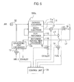
Fig. 6 is a block diagram showing the configuration of a fuel cellpower generation system 100a according to the second embodiment. As shown inFig. 6 , the second embodiment differs from the fuel cellpower generation system 100 of the foregoing first embodiment in that a third air blower 32 (temperature adjustment unit, temperature adjustment means) is provided instead of thecombustion burner 23 connected to thecathode electrode 11a of thefuel cell 11. That is, in the fuel cellpower generation system 100a shown inFig. 6 , unheated air sent out by thethird air blower 32 can be introduced into the oxidation-gas inlet of thecathode electrode 11a. - Moreover, in the fuel cell
power generation system 100 according to the second embodiment, as an air-heating heat exchanger 13a provided on the output side of thefirst air blower 12, used is one that is larger than the air-heating heat exchanger 13 shown inFig. 1 . Thus, air sent out by thefirst air blower 12 receives the heat of exhaust gas supplied to the air-heating heat exchanger 13a and is heated to a higher temperature. - Specifically, the air-
heating heat exchanger 13a shown inFig. 6 has a heat transfer area large enough to heat, to a predetermined temperature, air equivalent to an output ratio of "5" in the characteristic curve shown inFig. 4 . Supplying air at a low flow rate equivalent to an output ratio of "1" increases the temperature of a low temperature side of the air-heating heat exchanger 13a and thus reduces the temperature difference from the operating temperature of thefuel cell 11. For this reason, the temperature of thefuel cell 11 may fail to be maintained at 650°C. In this respect, in the second embodiment, in the case where the output ratio is small and thefuel cell 11 is operated at a low temperature, thethird air blower 32 sends out unheated air to lower the temperature of the air to be introduced into the oxidation gas inlet of thecathode 11a. In this way, the operating temperature of thefuel cell 11 can be suppressed to a low temperature. - In the following, processing steps by the
control unit 31 of the fuel cellpower generation system 100a according to the second embodiment will be described with reference to a flowchart shown inFig. 7 . - First, in step S31, when the host system outputs a power generation output command, the
control unit 31 receives this power generation output command. - In step S32, based on the power generation output command, the
control unit 31 determines the flow rates of thefirst air blower 12, thefirst fuel pump 14, and thethird air blower 32 that are suitable for outputting electric power corresponding to the power generation output command. Here, thecontrol unit 31 refers to the target temperature data map (not shown) of thefuel cell 11 which has been set in advance according to power generation outputs, for example. As mentioned above, a low temperature, e.g. 650°C, is set in the case where the electric power to be outputted is small, and a higher temperature, e.g. 750°C, is set in the case where the electric power to be outputted is large. In this way, it is possible, with acompact fuel cell 11, to widen the output power range and, at the same time, minimize the length of high temperature operation that accelerates durability deterioration. Moreover, the flow rates of the first andthird air blowers first fuel pump 14 can be set based on data of system experiments conducted in advance. - In step S33, the
control unit 31 determines the opening degrees of the fuel-flow-pathpressure adjustment valve 18 and the exhaust-flow-pathpressure adjustment valve 19 in accordance with the flow rates of theair blowers first fuel pump 14 set in the process of step S32. - In step S34, the
control unit 31 sends opening-degree adjustment signals to the fuel-flow-pathpressure adjustment valve 18 and the exhaust-flow-pathpressure adjustment valve 19 so as to obtain the opening degrees determined in the process of step S33. As a result, the fuel-flow-pathpressure adjustment valve 18 and the exhaust-flow-pathpressure adjustment valve 19 are adjusted to the determined opening degrees. - In step S35, the
control unit 31 sends a number-of-revolutions adjustment signal to thethird air blower 32 so as to obtain the flow rate thereof determined in the process of step S32. As a result, thethird air blower 32 is adjusted to the determined flow rate. Specifically, in the case where high output power is required, the flow rate of the air to be sent out by thethird air blower 32 is made lower than that in a case where the output power is low, thereby making higher the temperature of the air to be introduced into the oxidation-gas inlet of thecathode 11a. - By executing the processes of step S31 to S35 described above, the fuel cell
power generation system 100a can be prepared for changes to be made in the output power in steps S36 and S37 below. That is, excessive temperature increase and abnormal pressure increase of thefuel cell 11 can be suppressed. - Thereafter, in step S36, the
control unit 31 adjusts the power consumption of the external load to thereby adjust the output power of thefuel cell 11. - In step S37, the
control unit 31 sends number-of-revolutions adjustment signals to thefirst air blower 12 and thefirst fuel pump 14 so as to obtain the flow rates thereof determined in the process of step S32. As a result, thefirst air blower 12 and thefirst fuel pump 14 are adjusted to the determined flow rates. Consequently, the temperature of thefuel cell 11 can be controlled to a temperature suitable for the power consumption of the external load, and also the pressure of the exhaust gas can be controlled to a suitable pressure. - As described above, in the fuel cell
power generation system 100a according to the second embodiment, air sent out by thefirst air blower 12 is supplied to the oxidation-gas inlet of thecathode electrode 11 a of thefuel cell 11, and thethird air blower 32 is connected to the oxidation-gas inlet and air sent out by thethird air blower 32 is supplied thereto. - Thus, in the case where high output power is required, the flow rate of the air to be sent out by the
third air blower 32 is reduced to raise the temperature of the air to be introduced into the oxidation-gas inlet of thecathode electrode 11a and thereby raise the operating temperature of thefuel cell 11. Accordingly, the operable output can be improved significantly. Moreover, in a case of low output power, the flow rate of the air to be sent out by thethird air blower 32 is increased to lower the temperature of the air to be introduced into the oxidation-gas inlet of thecathode electrode 11 a. In this way, the operating temperature of thefuel cell 11 can be lowered. - Next, a fuel cell power generation system according to a third embodiment of the present invention will be described.
Fig. 8 is a block diagram showing the configuration of a fuel cellpower generation system 100b according to the third embodiment. As shown inFig. 8 , the third embodiment differs from the fuel cellpower generation system 100 of the foregoing first embodiment in that: thecombustion burner 23 connected to thecathode electrode 11a of thefuel cell 11 is not provided; the exhaust-flow-pathpressure adjustment valve 19 is not provided upstream of the reformer-heating heat exchanger 16; and a bypass flow rate adjustment valve 33 (temperature adjustment unit, temperature adjustment means) is provided on a high temperature side of an air-heating heat exchanger 13b. - Moreover, in the fuel cell
power generation system 100b according to the third embodiment, as the air-heating heat exchanger 13b provided on the output side of thefirst air blower 12, used is one that is larger than the air-heating heat exchanger 13 shown inFig. 1 . Thus, air sent out by thefirst air blower 12 receives the heat of exhaust gas supplied to the air-heating heat exchanger 13b and is heated to a higher temperature. - Specifically, the air-
heating heat exchanger 13b shown inFig. 8 has a heat transfer area large enough to heat, to a predetermined temperature, air equivalent to an output ratio of "5" in the characteristic curve shown inFig. 4 . Supplying air at a low flow rate equivalent to an output ratio of "1" increases the temperature of a low temperature side of the air-heating heat exchanger 13b and thus reduces the temperature difference from the operating temperature of thefuel cell 11. For this reason, the temperature of thefuel cell 11 may fail to be maintained at 650°C. In this respect, in the third embodiment, in the case where the output ratio is small and thefuel cell 11 is operated at a low temperature, the opening degree of the bypass flowrate adjustment valve 33 is adjusted such that exhaust gas to be supplied the high temperature side of the air-heating heat exchanger 13b bypasses it, thereby lowering the temperature of the air to be introduced into the oxidation gas inlet of thecathode 11a and thus adjusting the operating temperature of thefuel cell 11. - In the following, processing steps by the
control unit 31 of the fuel cellpower generation system 100b according to the third embodiment will be described with reference to a flowchart shown inFig. 9 . - First, in step S51, when the host system outputs a power generation output command, the
control unit 31 receives this power generation output command. - In step S52, based on the power generation output command, the
control unit 31 determines the flow rates of thefirst air blower 12 and thefirst fuel pump 14 that are suitable for outputting electric power corresponding to the power generation output command. Here, thecontrol unit 31 refers to the target temperature data map (not shown) of thefuel cell 11 which has been set in advance according to power generation outputs, for example. As mentioned above, a low temperature, e.g. 650°C, is set in the case where the electric power to be outputted is small, and a higher temperature, e.g. 750°C, is set in the case where the electric power to be outputted is large. In this way, it is possible to reduce the side of thefuel cell 11, widen the output power range and, at the same time, minimize the length of high temperature operation that accelerates durability deterioration. Moreover, the flow rates of thefirst air blower 12 and thefirst fuel pump 14 can be set based on data of system experiments conducted in advance. - In step S53, the
control unit 31 determines the opening degrees of the fuel-flow-pathpressure adjustment valve 18 and the bypass flowrate adjustment valve 33 in accordance with the flow rate of thefirst air blower 12 and the flow rate of thefirst fuel pump 14 set in the process of step S52. - In step S54, the
control unit 31 sends opening-degree adjustment signals to the fuel-flow-pathpressure adjustment valve 18 and the bypass flowrate adjustment valve 33 so as to obtain the opening degrees determined in the process of step S53. As a result, the fuel-flow-pathpressure adjustment valve 18 and the bypass flowrate adjustment valve 33 are adjusted to the determined opening degrees. - In step S55, the
control unit 31 sends an opening-degree adjustment signal for the bypass flowrate adjustment valve 33 so as to obtain a desired air heating amount. Specifically, thecontrol unit 31 sends an opening-degree adjustment signal that adjusts the amount of the exhaust gas to be supplied to the high temperature side of the air-heating heat exchanger 13b such that the temperature of the air heated on the low temperature side of the air-heating heat exchanger 13b becomes a desired temperature. As a result, the bypass flowrate adjustment valve 33 is adjusted to the determined opening degree. - By executing the processes of step S51 to S55 described above, the fuel cell
power generation system 100b can be prepared for changes to be made in the output power in steps S56 and S57 below. That is, excessive temperature increase and abnormal pressure increase of thefuel cell 11 can be suppressed. - Thereafter, in step S56, the
control unit 31 adjusts the power consumption of the external load to thereby adjust the output power of thefuel cell 11. - In step S57, the
control unit 31 sends number-of-revolutions adjustment signals to thefirst air blower 12 and thefirst fuel pump 14 so as to obtain the flow rates thereof determined in the process of step S52. As a result, thefirst air blower 12 and thefirst fuel pump 14 are adjusted to the determined flow rates. Consequently, the temperature of thefuel cell 11 can be controlled to a temperature suitable for the power consumption of the external load, and also the pressure of the exhaust gas can be controlled to a suitable pressure. - As described above, in the fuel cell
power generation system 100b according to the third embodiment, the bypass flowrate adjustment valve 33 is provided to the exhaust-gas inlet of the air-heating heat exchanger 13b, and the opening degree of the bypass flowrate adjustment valve 33 is adjusted to adjust the temperature of the air (oxidation gas) to be supplied to thecathode electrode 11a of thefuel cell 11 to a desired temperature. - Thus, in the case where high output power is required, the opening degree of the bypass flow
rate adjustment valve 33 is reduced to increase the flow rate of the exhaust gas to be supplied to the air-heating heat exchanger 13b, thus raising the temperature of the air to be introduced into the oxidation-gas inlet of thecathode electrode 11a and thereby raising the operating temperature of thefuel cell 11. Accordingly, the operable output can be improved significantly. Moreover, in a case of low output power, the opening degree of the bypass flowrate adjustment valve 33 is increased to reduce the flow rate of the exhaust gas to be supplied to the air-heating heat exchanger 13b, thus lowering the temperature of the air to be introduced into the oxidation-gas inlet of thecathode electrode 11a. In this way, the operating temperature of thefuel cell 11 can be lowered. - Each foregoing embodiment has described the case where the operating temperature of the
fuel cell 11 is changed within a range of 650°C to 750°C as an example. Note that the present invention is not limited to this case, and other temperature ranges can be employed. The temperature range to be set can be appropriately changed according to the operating environment of thefuel cell 11. - Although the fuel cell power generation system and the method of controlling a fuel cell power generation system of the present invention have been described hereinabove based on the illustrated embodiments, the present invention is not limited to these, and the configuration of each component can be replaced with any suitable configuration having a similar function.
- This application claims the benefit of priority from Japanese Patent Application No.
2011-011707, filed on January 24, 2011 - The fuel cell power generation system according to each embodiment of the present invention controls the operating temperature of the
fuel cell 11 by controlling the temperature of the oxidation gas to be supplied to the oxidation-gas inlet, when controlling the amount of power generation of thefuel cell 11 on the basis of the power output required by the load. Specifically, in the case where the required output of thefuel cell 11 is high, the temperature of the oxidation gas to be supplied to the oxidation-gas inlet is made higher than that in a case where the required output is low, thereby making the operating temperature of thefuel cell 11 higher. In this way, the operable output can be significantly improved. For example, it is possible to widen the output ratio between the output during the highest efficiency operation, which is a relatively low output operating point, and the output during the highest output operation. Moreover, in the case where the required power output is low, the temperature of the oxidation gas to be supplied to the oxidation-gas inlet is reduced to lower the operating temperature of thefuel cell 11. Accordingly, durability deterioration can be prevented. The fuel cell power generation system according to each embodiment of the present invention is significantly useful in the case of operating afuel cell 11 at a suitable temperature according to changes in the required output. Hence, the fuel cell power generation system according to each embodiment of the present invention is industrially applicable. -
- 11
- fuel cell
- 12
- first air blower (oxidation-gas supply unit)
- 13, 13a, 13b
- air-heating heat exchanger (heat exchange unit)
- 15
- fuel reformer
- 16
- reformer-heating heat exchanger (reformer heating unit)
- 18
- fuel-flow-path pressure adjustment valve (second pressure adjustment valve)
- 19
- exhaust-flow-path pressure adjustment valve (first pressure adjustment valve)
- 23
- combustion burner (temperature adjustment unit)
- 31
- control unit
- 32
- third air blower (temperature adjustment unit)
- 33
- bypass flow rate adjustment valve (temperature adjustment unit)
- 100
- fuel cell power generation system
- L1
- fuel-gas flow path
- L2
- exhaust-gas flow path
Claims (8)
- A fuel cell power generation system, comprising:a fuel cell configured to generate electric power upon supply of oxidation gas and fuel gas;a temperature adjustment unit configured to adjust a temperature of the oxidation gas to be supplied to an oxidation-gas inlet of the fuel cell; anda control unit configured to, in a case where a required output of the fuel cell is high, output a temperature control signal to the temperature adjustment unit such that the temperature of the oxidation gas to be supplied to the oxidation-gas inlet is made higher than that in a case where the required output is low, whereinin the case where the required output of the fuel cell is high, an operating temperature of the fuel cell is made higher than that in the case where the required output is low.
- The fuel cell power generation system according to claim 1, wherein
the temperature adjustment unit includes a combustion burner configured to supply heated oxidation gas to the oxidation-gas inlet, and
in the case where the required output of the fuel cell is high, the control unit outputs the temperature control signal such that an amount of heat generation of the combustion burner is made greater than that in the case where the required output is low. - The fuel cell power generation system according to claim 1, further comprising:an oxidation-gas supply unit configured to send out the oxidation gas to the oxidation-gas inlet of the fuel cell; anda heat exchange unit configured to heat the oxidation gas sent out by the oxidation-gas supply unit by using heat of exhaust gas of the fuel cell, whereinthe temperature adjustment unit includes a blower provided to a different system from the oxidation-gas supply unit and configured to send out oxidation gas to the oxidation-gas inlet, andin the case where the required output of the fuel cell is high, the control unit outputs the temperature control signal such that a flow rate of the oxidation gas to be sent out by the blower is made lower than that in the case where the required output is low.
- The fuel cell power generation system according to claim 1, further comprising:an oxidation-gas supply unit configured to send out the oxidation gas to the oxidation-gas inlet of the fuel cell; anda heat exchange unit configured to heat the oxidation gas sent out by the oxidation-gas supply unit by using heat of exhaust gas of the fuel cell, whereinthe temperature adjustment unit includes a flow rate adjustment valve which is capable of adjusting an amount of the exhaust gas to be supplied to the heat exchange unit by separating a part of the exhaust gas to be supplied to the heat exchange unit, andin the case where the required output of the fuel cell is high, the control unit outputs the temperature control signal such that the amount of the exhaust gas to be supplied to the heat exchange unit at the flow rate adjustment valve is made greater than that in the case where the required output is low.
- The fuel cell power generation system according to any one of claims 1 to 3, further comprising:a fuel reformer configured to reform the fuel gas to be supplied to the fuel cell;a reformer heating unit configured to heat the fuel reformer by using exhaust gas discharged by the fuel cell; anda first pressure adjustment valve provided to an inlet flow path of the reformer heating unit for the exhaust gas and configured to adjust a pressure of the exhaust gas by discharging a part of the exhaust gas, andthe control unit outputs a pressure adjustment signal to the first pressure adjustment valve such that the pressure of the exhaust gas of the fuel cell becomes a desired pressure.
- The fuel cell power generation system according to any one of claims 1 to 4, further comprising:a fuel reformer configured to reform the fuel gas to be supplied to the fuel cell;a reformer heating unit configured to heat the fuel reformer by using exhaust gas discharged by the fuel cell; anda second pressure adjustment valve provided to a flow path for introducing fuel gas discharged by the fuel cell into an inlet of the reformer heating unit, and configured to introduce a part of the fuel gas discharged by the fuel cell into the reformer heating unit; andthe control unit outputs a pressure adjustment signal to the second pressure adjustment valve such that a pressure of the fuel gas to be supplied to the fuel reformer becomes a desired pressure.
- A fuel cell power generation system, comprising:a fuel cell for generating electric power upon supply of oxidation gas and fuel gas;temperature adjustment means for adjusting a temperature of the oxidation gas to be supplied to an oxidation-gas inlet of the fuel cell; andcontrol means for, in a case where a required output of the fuel cell is high, outputting a temperature control signal to the temperature adjustment means such that the temperature of the oxidation gas to be supplied to the oxidation-gas inlet is made higher than that in a case where the required output is low, whereinin the case where the required output of the fuel cell is high, an operating temperature of the fuel cell is made higher than that in the case where the required output is low.
- A method of controlling a fuel cell power generation system including a fuel cell configured to generate electric power upon supply of oxidation gas and fuel gas, and a temperature adjustment unit configured to adjust a temperature of the oxidation gas to be supplied to an oxidation-gas inlet of the fuel cell, the method comprising:in a case where a required output of the fuel cell is high, outputting a temperature control signal to the temperature adjustment unit such that the temperature of the oxidation gas to be supplied to the oxidation-gas inlet is made higher than that in a case where the required output is low; andcausing the temperature adjustment unit to adjust the temperature of the oxidation gas in accordance with the temperature control signal such that in the case where the required output of the fuel cell is high, an operating temperature of the fuel cell is made higher than that in the case where the required output is low.
Applications Claiming Priority (2)
| Application Number | Priority Date | Filing Date | Title |
|---|---|---|---|
| JP2011011707 | 2011-01-24 | ||
| PCT/JP2012/051400 WO2012102253A1 (en) | 2011-01-24 | 2012-01-24 | Fuel cell power generation system, and method for control of fuel cell power generation system |
Publications (2)
| Publication Number | Publication Date |
|---|---|
| EP2669980A1 true EP2669980A1 (en) | 2013-12-04 |
| EP2669980A4 EP2669980A4 (en) | 2016-03-23 |
Family
ID=46580819
Family Applications (1)
| Application Number | Title | Priority Date | Filing Date |
|---|---|---|---|
| EP12740026.5A Withdrawn EP2669980A4 (en) | 2011-01-24 | 2012-01-24 | Fuel cell power generation system, and method for control of fuel cell power generation system |
Country Status (5)
| Country | Link |
|---|---|
| US (1) | US20130302708A1 (en) |
| EP (1) | EP2669980A4 (en) |
| JP (1) | JP5888245B2 (en) |
| CN (1) | CN103339776B (en) |
| WO (1) | WO2012102253A1 (en) |
Families Citing this family (15)
| Publication number | Priority date | Publication date | Assignee | Title |
|---|---|---|---|---|
| KR101397091B1 (en) * | 2012-12-28 | 2014-05-19 | 포스코에너지 주식회사 | Fuel cell system |
| JP6303282B2 (en) * | 2013-04-11 | 2018-04-04 | 日産自動車株式会社 | Fuel cell power generation system |
| JP6323241B2 (en) * | 2014-08-06 | 2018-05-16 | 日産自動車株式会社 | Fuel cell power generation system |
| JP6390253B2 (en) * | 2014-08-06 | 2018-09-19 | 日産自動車株式会社 | Fuel cell power generation system |
| KR101679971B1 (en) * | 2015-05-14 | 2016-11-25 | 현대자동차주식회사 | Failure diagonistic apparatus and method for air supply system of fuel cell |
| JP6134832B1 (en) * | 2016-03-30 | 2017-05-24 | 東京瓦斯株式会社 | Fuel cell system |
| JP6843531B2 (en) * | 2016-06-27 | 2021-03-17 | 三菱パワー株式会社 | Fuel cell control device and control method and power generation system |
| JP6443405B2 (en) * | 2016-07-04 | 2018-12-26 | トヨタ自動車株式会社 | Heat, hydrogen generator |
| JP6443404B2 (en) * | 2016-07-04 | 2018-12-26 | トヨタ自動車株式会社 | Heat, hydrogen generator |
| FR3054932B1 (en) | 2016-08-03 | 2021-12-24 | Commissariat Energie Atomique | SYSTEM FOR REGULATING THE TEMPERATURE AND PRESSURE OF A HIGH TEMPERATURE ELECTROLYZER (SOEC) OPERATING IN A REVERSIBLE WAY IN A FUEL CELL (SOFC) |
| CN106299410B (en) * | 2016-09-29 | 2019-06-14 | 江苏科技大学 | A kind of solid oxide fuel cell power generating system using residual fuel self-heating |
| US10158135B2 (en) * | 2016-10-25 | 2018-12-18 | Lg Fuel Cell Systems Inc. | Steam reformer bypass plenum and flow controller |
| CN110998942B (en) * | 2017-08-14 | 2020-11-17 | 日产自动车株式会社 | Fuel cell system and warm-up method for fuel cell system |
| CN109994760B (en) | 2018-01-03 | 2022-06-28 | 通用电气公司 | Temperature control system and method for fuel cell system and fuel cell system |
| JP6806824B2 (en) * | 2019-02-27 | 2021-01-06 | 三菱パワー株式会社 | Fuel cell power generation system |
Family Cites Families (16)
| Publication number | Priority date | Publication date | Assignee | Title |
|---|---|---|---|---|
| JPS62160668A (en) * | 1986-01-10 | 1987-07-16 | Hitachi Ltd | Operation method for fuel cell power generation system |
| US7141326B2 (en) * | 2001-04-06 | 2006-11-28 | Honda Giken Kogyo Kabushiki Kaisha | Warm-up apparatus for fuel cell |
| JP2003115315A (en) | 2001-10-05 | 2003-04-18 | Nippon Steel Corp | Operational method of solid electrolyte type fuel cell |
| JP3826770B2 (en) * | 2001-11-16 | 2006-09-27 | 日産自動車株式会社 | Fuel reforming system |
| DE20210130U1 (en) * | 2002-07-01 | 2004-03-04 | Zentrum für Sonnenenergie- und Wasserstoff-Forschung Baden-Württemberg Gemeinnützige Stiftung | Fuel cell test system has anode and cathode gas sources, gas feed lines with flow regulators corresponding to gas sources, output gas lines, single cell voltage measurement device, operating devices. |
| JP2004349214A (en) | 2003-05-26 | 2004-12-09 | Mitsubishi Materials Corp | Operation method of solid oxide fuel cell |
| GB2411043B (en) * | 2004-02-10 | 2007-09-19 | Ceres Power Ltd | A method and apparatus for operating an intermediate-temperature solid-oxide fuel cell stack |
| US7807313B2 (en) * | 2004-12-21 | 2010-10-05 | Ultracell Corporation | Compact fuel cell package |
| JP4892875B2 (en) * | 2005-06-15 | 2012-03-07 | 日産自動車株式会社 | Fuel cell control device and fuel cell system |
| JP4981281B2 (en) * | 2005-08-29 | 2012-07-18 | 電源開発株式会社 | FUEL CELL SYSTEM AND CONTROL METHOD FOR FUEL CELL SYSTEM |
| JP2007122897A (en) * | 2005-10-25 | 2007-05-17 | Nissan Motor Co Ltd | Fuel cell system |
| JP2007265937A (en) * | 2006-03-30 | 2007-10-11 | Osaka Gas Co Ltd | Polymer electrolyte fuel cell system and its control method |
| JP4949743B2 (en) * | 2006-06-07 | 2012-06-13 | 株式会社日立製作所 | Solid oxide fuel cell system and starting method thereof |
| JP2008300251A (en) * | 2007-06-01 | 2008-12-11 | Honda Motor Co Ltd | Fuel cell cogeneration device |
| CN101499534B (en) * | 2008-01-31 | 2010-12-15 | 中国科学院宁波材料技术与工程研究所 | Distributed combined heat and power generation system of solid-oxide fuel battery |
| JP2009205868A (en) * | 2008-02-26 | 2009-09-10 | Think Tank Phoenix:Kk | Solid oxide fuel cell system and solid oxide fuel cell |
-
2012
- 2012-01-24 EP EP12740026.5A patent/EP2669980A4/en not_active Withdrawn
- 2012-01-24 US US13/980,963 patent/US20130302708A1/en not_active Abandoned
- 2012-01-24 CN CN201280006346.1A patent/CN103339776B/en not_active Expired - Fee Related
- 2012-01-24 JP JP2012554792A patent/JP5888245B2/en active Active
- 2012-01-24 WO PCT/JP2012/051400 patent/WO2012102253A1/en active Application Filing
Also Published As
| Publication number | Publication date |
|---|---|
| JPWO2012102253A1 (en) | 2014-06-30 |
| WO2012102253A1 (en) | 2012-08-02 |
| CN103339776A (en) | 2013-10-02 |
| CN103339776B (en) | 2015-08-26 |
| JP5888245B2 (en) | 2016-03-16 |
| US20130302708A1 (en) | 2013-11-14 |
| EP2669980A4 (en) | 2016-03-23 |
Similar Documents
| Publication | Publication Date | Title |
|---|---|---|
| EP2669980A1 (en) | Fuel cell power generation system, and method for control of fuel cell power generation system | |
| US8855945B2 (en) | Feedforward control of the volume flow in a hydraulic system | |
| WO2006126715A1 (en) | Fuel cell system | |
| JP2006294621A (en) | Method and device for controlled solid oxide fuel cell (sofc)/turbine hybrid power generation | |
| US7465325B2 (en) | Fuel reforming system and warmup method thereof | |
| EP2461407A1 (en) | Fuel cell device | |
| CN113013441A (en) | Fuel cell system temperature control method | |
| US11424459B2 (en) | Fuel cell system | |
| US7169492B2 (en) | Method for regulating operation of fuel cell installations controlled according to heat and/or power requirement | |
| JP4828078B2 (en) | Method for controlling oxidant flow rate in fuel cell system | |
| KR20220108796A (en) | Improved fuel cell systems and methods | |
| KR101128923B1 (en) | Fuel cell system with a recirculation strand | |
| WO2014006988A1 (en) | Fuel cell generation system, and method of controlling fuel cell generation system | |
| JP2006226639A (en) | Cogeneration system | |
| KR101319708B1 (en) | Method for temperature control in a fuel cell system and fuel cell system | |
| JP6303282B2 (en) | Fuel cell power generation system | |
| JP6390253B2 (en) | Fuel cell power generation system | |
| CN113581016A (en) | Idle speed control method of fuel cell system and related apparatus | |
| JP2007242531A (en) | Fuel cell system | |
| JP6160757B1 (en) | Fuel cell system and operation method thereof | |
| JP2007194080A (en) | Fuel cell system | |
| EP4016679A1 (en) | Method for operating fuel cell system and fuel cell system | |
| JP6323241B2 (en) | Fuel cell power generation system | |
| JP6102301B2 (en) | Fuel cell system | |
| US20240047712A1 (en) | Cooling system for fuel cell |
Legal Events
| Date | Code | Title | Description |
|---|---|---|---|
| PUAI | Public reference made under article 153(3) epc to a published international application that has entered the european phase |
Free format text: ORIGINAL CODE: 0009012 |
|
| 17P | Request for examination filed |
Effective date: 20130807 |
|
| AK | Designated contracting states |
Kind code of ref document: A1 Designated state(s): AL AT BE BG CH CY CZ DE DK EE ES FI FR GB GR HR HU IE IS IT LI LT LU LV MC MK MT NL NO PL PT RO RS SE SI SK SM TR |
|
| DAX | Request for extension of the european patent (deleted) | ||
| RA4 | Supplementary search report drawn up and despatched (corrected) |
Effective date: 20160218 |
|
| RIC1 | Information provided on ipc code assigned before grant |
Ipc: H01M 8/04701 20160101ALI20160212BHEP Ipc: H01M 8/04746 20160101ALI20160212BHEP Ipc: H01M 8/0612 20160101ALI20160212BHEP Ipc: H01M 8/06 20060101ALI20160212BHEP Ipc: H01M 8/04014 20160101ALN20160212BHEP Ipc: H01M 8/04537 20160101ALI20160212BHEP Ipc: H01M 8/04007 20160101ALI20160212BHEP Ipc: H01M 8/04 20060101AFI20160212BHEP |
|
| STAA | Information on the status of an ep patent application or granted ep patent |
Free format text: STATUS: THE APPLICATION HAS BEEN WITHDRAWN |
|
| 18W | Application withdrawn |
Effective date: 20160420 |