EP2669747B1 - Image forming apparatus and toner case - Google Patents
Image forming apparatus and toner case Download PDFInfo
- Publication number
- EP2669747B1 EP2669747B1 EP13168471.4A EP13168471A EP2669747B1 EP 2669747 B1 EP2669747 B1 EP 2669747B1 EP 13168471 A EP13168471 A EP 13168471A EP 2669747 B1 EP2669747 B1 EP 2669747B1
- Authority
- EP
- European Patent Office
- Prior art keywords
- lever
- main body
- cover
- toner
- stopper
- Prior art date
- Legal status (The legal status is an assumption and is not a legal conclusion. Google has not performed a legal analysis and makes no representation as to the accuracy of the status listed.)
- Active
Links
- 230000008878 coupling Effects 0.000 claims description 28
- 238000010168 coupling process Methods 0.000 claims description 28
- 238000005859 coupling reaction Methods 0.000 claims description 28
- 230000005540 biological transmission Effects 0.000 claims description 20
- 238000003756 stirring Methods 0.000 claims description 13
- 230000002452 interceptive effect Effects 0.000 claims description 10
- 230000002787 reinforcement Effects 0.000 claims description 5
- 238000011161 development Methods 0.000 description 9
- 238000010586 diagram Methods 0.000 description 8
- 238000004891 communication Methods 0.000 description 5
- 238000000034 method Methods 0.000 description 5
- 238000004806 packaging method and process Methods 0.000 description 3
- 230000008901 benefit Effects 0.000 description 2
- 238000004140 cleaning Methods 0.000 description 2
- 230000003247 decreasing effect Effects 0.000 description 2
- 238000007599 discharging Methods 0.000 description 2
- 238000003780 insertion Methods 0.000 description 2
- 230000037431 insertion Effects 0.000 description 2
- 239000005022 packaging material Substances 0.000 description 2
- 238000007639 printing Methods 0.000 description 2
- 238000007789 sealing Methods 0.000 description 2
- 238000012546 transfer Methods 0.000 description 2
- 238000003384 imaging method Methods 0.000 description 1
- 238000010348 incorporation Methods 0.000 description 1
- 238000009434 installation Methods 0.000 description 1
- 239000004973 liquid crystal related substance Substances 0.000 description 1
- 238000012856 packing Methods 0.000 description 1
- 239000002985 plastic film Substances 0.000 description 1
- 238000003825 pressing Methods 0.000 description 1
Images


Classifications
-
- G—PHYSICS
- G03—PHOTOGRAPHY; CINEMATOGRAPHY; ANALOGOUS TECHNIQUES USING WAVES OTHER THAN OPTICAL WAVES; ELECTROGRAPHY; HOLOGRAPHY
- G03G—ELECTROGRAPHY; ELECTROPHOTOGRAPHY; MAGNETOGRAPHY
- G03G15/00—Apparatus for electrographic processes using a charge pattern
- G03G15/06—Apparatus for electrographic processes using a charge pattern for developing
- G03G15/08—Apparatus for electrographic processes using a charge pattern for developing using a solid developer, e.g. powder developer
- G03G15/0822—Arrangements for preparing, mixing, supplying or dispensing developer
- G03G15/0877—Arrangements for metering and dispensing developer from a developer cartridge into the development unit
- G03G15/0881—Sealing of developer cartridges
- G03G15/0882—Sealing of developer cartridges by a peelable sealing film
-
- G—PHYSICS
- G03—PHOTOGRAPHY; CINEMATOGRAPHY; ANALOGOUS TECHNIQUES USING WAVES OTHER THAN OPTICAL WAVES; ELECTROGRAPHY; HOLOGRAPHY
- G03G—ELECTROGRAPHY; ELECTROPHOTOGRAPHY; MAGNETOGRAPHY
- G03G15/00—Apparatus for electrographic processes using a charge pattern
- G03G15/06—Apparatus for electrographic processes using a charge pattern for developing
- G03G15/08—Apparatus for electrographic processes using a charge pattern for developing using a solid developer, e.g. powder developer
- G03G15/0822—Arrangements for preparing, mixing, supplying or dispensing developer
- G03G15/0877—Arrangements for metering and dispensing developer from a developer cartridge into the development unit
- G03G15/0881—Sealing of developer cartridges
- G03G15/0886—Sealing of developer cartridges by mechanical means, e.g. shutter, plug
-
- G—PHYSICS
- G03—PHOTOGRAPHY; CINEMATOGRAPHY; ANALOGOUS TECHNIQUES USING WAVES OTHER THAN OPTICAL WAVES; ELECTROGRAPHY; HOLOGRAPHY
- G03G—ELECTROGRAPHY; ELECTROPHOTOGRAPHY; MAGNETOGRAPHY
- G03G21/00—Arrangements not provided for by groups G03G13/00 - G03G19/00, e.g. cleaning, elimination of residual charge
- G03G21/16—Mechanical means for facilitating the maintenance of the apparatus, e.g. modular arrangements
- G03G21/1604—Arrangement or disposition of the entire apparatus
- G03G21/1623—Means to access the interior of the apparatus
- G03G21/1633—Means to access the interior of the apparatus using doors or covers
Definitions
- the present disclosure relates to an image forming apparatus and a toner case installed to the image forming apparatus.
- An electrographic image forming apparatus carries out the development process by supplying a toner (a developer) from a development device to an electrostatic latent image formed on the surface of a photosensitive drum or the like.
- the toner used in such development process is supplied from a toner case configured to be attachable and detachable to an apparatus main body of the image forming apparatus.
- the above-mentioned toner case includes a case main body having a discharge port discharging the toner and a shutter opening/closing the discharge port.
- the shutter rotatably installed to the case main body and opening/closing the discharge port in accordance with the rotation is known.
- a locking member attached to the toner case locks the shutter in a closing state, thereby preventing the toner from leaking from the toner case during transport of the toner case.
- the above-mentioned technique is provided presupposing the transport of single toner case.
- the toner case is separately packed from the apparatus main body, and accordingly, the capacity and number of the packaging material are unnecessarily increased, thereby incurring an increase of a packaging cost.
- the imaging forming apparatus including the tone case configured as mentioned above, there is a fear that the toner case is installed, in a situation of the shutter closing the discharge port, to the apparatus main body by operation mistake of a worker, such as a user.
- a technique mentioned above does not take measures for solving the fear and it is difficult to prevent the operation mistake of the worker.
- an image forming apparatus includes a toner case, an apparatus main body and a cover.
- the toner case is configured to include a case main body having a discharge port configured to discharge a toner, a shutter configured to open/close the discharge port, and a lever connected with the shutter.
- the toner case is attachably/detachably installed.
- the cover is openably/closably attached to the apparatus main body and configured to cover at least a part of the toner case.
- the lever is configured to be shifted to a first position in order to make the shutter close the discharge port and to allow the close of the cover without interfering with the cover, to a second position in order to make the shutter close the discharge port and to interfere with the cover, or to a third posit ion in order to make the shutter open the discharge port and to allow the close of the cover without interfering with the cover.
- a toner case is attachably/detachably installed to an apparatus main body of an image forming apparatus and covered by a cover openably/closably attached to the apparatus main body.
- the toner case includes a case main body, a shutter and a lever.
- the case main body has a discharge port configured to discharge a toner.
- the shutter is configured to open/close the discharge port.
- the lever is configured to connect with the shutter and to be shifted to a first position in order to make the shutter close the discharge port and to allow the close of the cover without interfering with the cover, to a second position in order to make the shutter close the discharge port and to interfere with the cover, or to a third position in order to make the shutter open the discharge port and to allow the close of the cover without interfering with the cover.
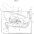
- FIG. 1 is a schematic diagram schematically showing the printer according to an embodiment of the present disclosure. Hereinafter, it will be described so that the front side of the printer 1 is positioned at the left-hand side of FIG. 1 .
- the printer 1 includes a box-formed printer main body 2 (apparatus main body). To a lower part of the printer main body 2, a sheet feeding cartridge 3 configured to store sheets (not shown) is installed and, on the top surface of the printer main body 2, an ejecting tray 4 is mounted. To the upper front part of the printer main body 2, a toner container 5 as a toner case is attachably/detachably installed and, above the toner container 5, an upper cover 6(cover) is openably/closably attached.
- an exposure device 7 composed of a laser scanning unit (LSU) is installed below the sheet ejecting tray 4.
- an image forming unit 8 is installed below the exposure device 7, an image forming unit 8 is installed.
- a photosensitive drum 10 as an image carrier is rotatably installed.
- a charger 11, a development device 12, a transfer roller 13 and a cleaning device 14 are located along a rotating direction (refer to arrow X in FIG. 1 ) of the photosensitive drum 10.
- a sheet conveying path 15 is arranged inside the printer main body 2.
- a sheet feeder 16 is positioned at an upper stream end of the conveying path 15.
- a transferring unit 17 constructed of the photosensitive drum 10 and transfer roller 13 is positioned.
- a fixing device 18 is positioned at a lower stream part of the conveying path 15.
- a sheet ejecting unit 20 is positioned at a lower stream end of the conveying path 15.
- an inversion path 21 for duplex printing is arranged below the conveying path 15.
- the surface of the photosensitive drum 10 is electrically charged by the charger 11. Then, exposure corresponding to the image data on the photosensitive drum 10 is carried out by a laser (refer to two-dot chain line P in FIG. 1 ) from the exposure device 7, thereby forming an electrostatic latent image on the surface of the photosensitive drum 10. Subsequently, the electrostatic latent image is developed to a toner image with a toner (a developer) in the development device 12.
- a sheet fed from the sheet feeding cartridge 3 by the sheet feeder 16 is conveyed to the transferring unit 17 in a suitable timing for the above-mentioned image forming operation, and then, the toner image on the photosensitive drum 10 is transferred onto the sheet in the transferring unit 17.
- the sheet with the transferred toner image is conveyed to a lower stream on the conveying path 15 to go forward to the fixing device 18, and then, the toner image is fixed on the sheet in the fixing device 18.
- the sheet with the fixed toner image is ejected from the sheet ejecting unit 20 to the sheet ejecting tray 4. Toner remained on the photosensitive drum 10 is collected by the cleaning device 14.
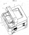
- FIG. 2 is a perspective view showing the printer in a situation, in which the upper cover is opened, according to the embodiment of the present disclosure.
- FIG. 3 is a right top perspective view showing the toner container in the printer according to the embodiment of the present disclosure.
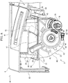
- FIG. 4 is a back perspective sectional view showing the toner container in the printer according to the embodiment of the present disclosure.
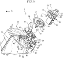
- FIG. 5 is an exploded perspective view showing the toner container in the printer according to the embodiment of the present disclosure.
- FIG. 6 is a front right perspective view showing the toner container in a situation, in which a lever is detached from a case main body, in the printer according to the embodiment of the present disclosure.
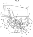
- FIG. 7 is a right side view showing the toner container in the printer according to the embodiment of the present disclosure.
- FIG. 4 is the back perspective sectional view
- the left-hand and right-hand sides of the figure are converse to the actual left-hand and right-hand sides. That is, the right-hand side illustrated in FIG. 4 is the left-hand side of the toner container 5 and the left-hand side illustrated in FIG. 4 is the right-hand side of the toner container 5.
- the toner container 5 is located below the upper cover 6.
- the toner container 5 is also attachably/detachably installed at a top surface of the development device 12 (refer to FIG. 1 ) to the printer main body 2.
- the toner container 5 is formed in an extended-shape in left and right directions or a horizontal direction.
- the toner container 5 includes a box-formed case main body 22 with an opened top surface, a conveying screw (a rotating member) 23, a stirring paddle (another rotating member) 24, a covering body 25, a lever 26, a transmitting member 27 and a shutter 28.
- the conveying screw 23 is installed to a lower rear part of the case main body 22.
- the stirring paddle 24 is installed near a center part of the case main body 22.
- the covering body 25 covers the top surface of the case main body 22.
- the lever 26 is attached to a right end of the case main body 22.
- the transmitting member 27 is placed on the right end of the case main body 22 together with the lever 26.
- the shutter 28 is attached on a right bottom end of the case main body 22.
- the transmitting member 27 is omitted in FIGS. 6 and 7 .
- the case main body 22 is formed in an extended-shape in the horizontal direction to contain the toner.
- a toner filling port 31 is formed and the toner filling port 31 is closed by a cap 32.
- a main body side flange 33 is formed on the circumference of a top end of the case main body 22 .
- a cylinder-formed discharge duct 34 is protruded to a right direction and, in a right end of the discharge duct 34, anaperture 36 is formed.
- a discharge port 35 discharging the toner is bored.
- a sealing member 37 is attached and, in the sealing member 37, a communication port 38 is bored at a correspondent position to the discharge port 35.
- a cylinder-formed boss 42 having a communication hole 41 is protruded to a right direction (an outside direction).
- a restrain rib 43 is protruded to an upper backward direction of the boss 42.
- a protrusion 44 is formed below the first restrain rib 43.
- a stopper 45 is protruded to an upper forward direction of the boss 42.
- the stopper 45 is connected with the restrain rib 43 by a connecting rib 46.
- the stopper 45 includes a curved piece 47, an engagement piece 48, a reinforcement piece 49 and a connection piece 50.
- the curved piece 47 curves in an arc-liked shape around the boss 42.
- the engagement piece 48 is connected with a rear side of an upper part of the curved piece 47.
- the reinforcement piece 49 is located above the engagement piece 48.
- the connection piece 50 connects the engagement piece 48 and reinforcement piece 49.
- On a lower part and an intermediate part in upper and lower directions or a vertical direction of the curved piece 47 support pieces 51 are protruded backward.
- the engagement piece 48 is formed in a U-shape laid on side to include a pair of upper and lower engagement plates 52.
- inclined parts 53 are respectively formed in the reinforcement piece 49 and engagement plates 52.
- Each inclined part 53 inclines so that protruded length from the right surface of the right end wall 40 of the case main body 22 is gradually lengthen from a front side to a rear side.
- the conveying screw 23 is formed in an extended-shape in the horizontal direction and installed to the case main body 22 in a rotatable state.
- the conveying screw 23 includes a bar-formed rotating shaft 54 and a spiral fin 55 concentrically mounted on the circumference of the rotating shaft 54.
- a left end of the rotating shaft 54 is pivotally supported by the left end wall 30 of the case main body 22.
- Right side parts of the rotating shaft 54 and spiral fin 55 are inserted into the discharge duct 34.
- a right end of the rotating shaft 54 protrudes from the discharge duct 34 via the aperture 36 to the right direction and, on the protruding part, a conveying gear 56 is fixedly attached.
- the stirring paddle 24 is located above and in front of the conveying screw 23 and formed in an extended-shape in the horizontal direction.
- the stirring paddle 24 is installed to the case main body 22 in a rotatable state.
- the stirring paddle 24 includes a supporting frame 57 formed in a frame plate-liked shape and a sheet-formed stirring fin 58 supported by the supporting frame 57. Left and right ends (both horizontal ends) of the supporting frame 57 are pivotally supported by the left end wall 30 and right end wall 40 of the case main body 22.
- the stirring fin 58 is formed out of plastic sheet, e.g. lumirror. As shown in FIG. 4 , one side of the stirring fin 58 is fixedly attached onto the supporting frame 57 along the horizontal direction.
- a covering body side flange 59 is formed in the correspondent form to the main body side flange 33 of the case main body 22.
- the main body side flange 33 and covering body side flange 59 are ultrasonic-welded together so that the case main body 22 and covering body 25 are unified.
- the lever 26 includes a lever main body 60 with a circular profile in a side view.
- the lever main body 60 is attached on the circumference of the boss 42 arranged on the right surface of the right end wall 40 of the case main body 22.
- the lever 26 is rotatably supported to the case main body 22 so that the lever 26 turns along the right surface of the right end wall 40 of the case main body 22.
- a gripper 61 is protruded to the outside in the radial direction. A top end of the gripper 61 extends to the right side of the covering body 25.
- the gripper 61 is hollow and, in a lower front part of the gripper 61, a depression 62 is formed.
- a protrusion piece 63 is protruded to the outside in the radial direction at a front side of the gripper 61.
- lever side gear 64 is formed on the circumference of a lower rear part of the lever main body 60.
- the transmitting member 27 includes a disc-formed transmitting member main body 65.
- a transmission coupling 66 is protruded in the form of a triangle shape in a side view.
- the transmission coupling 66 is attachably/detachably jointed to a drive coupling 90 (refer to FIG. 9C ) connected with a driver 91 (refer to FIG. 9C ), such a motor. Accordingly, when the driver 91 makes the drive coupling rotates, this rotation is transmitted to the transmitting member 27, and then, the transmitting member 27 rotates.
- an insertion piece 67 is protruded on a left surface (an internal surface) of the transmitting member main body 65.
- the insertion piece 67 is inserted into the communication hole 41 bored in the boss 42 of the case main body 22, and then, jointed to the supporting frame 57 of the stirring paddle 24. Accordingly, when the transmitting member 27 rotates, this rotation is transmitted to the stirring paddle 24, and then, the stirring paddle 24 rotates so that the toner in the case main body 22 is stirred and conveyed to the conveying screw 23.
- a transmission gear 68 is formed on the circumference of the transmitting member main body 65.
- the transmission gear 68 meshes with the conveying gear 56 of the conveying screw 23. Accordingly, when the transmitting member 27 rotates, this rotation is transmitted to the conveying screw 23, and then, the conveying screw 23 rotates so that the toner in the case main body 22 is discharged from the discharge port 35 and filled into the development device 12 (refer to FIG. 1 ).
- an aperture 69 curved in an arc-liked shape is bored.
- the shutter 28 is formed in a roughly cylinder-liked shape and rotatably installed to the circumference of the discharge duct 34 of the case main body 22.
- a discharge aperture 70 is bored in a lower surface of the shutter 28.
- a roughly fan-formed guiding piece 71 is protruded.
- an arc-formed guiding hole 72 is formed in the guiding piece 71 and, with the guiding hole 72, the protrusion 44 of the case main body 22 engages.
- a cylinder-formed bearing 73 is formed and, into the bearing 73, the right end of the rotating shaft 54 of conveying screw 23 is pivotally supported.
- a gear box 74 is attached and the gear box 74 houses the conveying gear 56.
- a communication aperture 75 is formed so that the conveying gear 56 can be housed in the gear box 74 via the communication aperture 75.
- the shutter 28 is provided with a shutter side gear 76.
- the shutter side gear 76 meshes with the lever side gear 64 of the lever 26.
- the lever 26 is connected to the shutter 28 so that the shutter 28 turns in the opposite direction to the lever 26 accompanying to the turn of the lever 26.
- an elliptic locking piece 77 is attached on the right end of the shutter 28.
- a pressing protrusion 78 is formed at the right side of the discharge aperture 70.
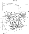
- FIG. 8 is a perspective view showing the printer in a situation, in which the upper cover is closed, according to the embodiment of the present disclosure.
- the terms of upper and lower, left and right, and front and back (rear) are used so as to indicate the directions in view of the closed upper cover (refer to FIG. 8 ).
- the upper cover 6 includes an upper plate 81 and a front plate 82 and is formed with a roughly L-shaped section.
- the upper plate 81 covers an upper surface side of the toner container 5 and the front plate 82 covers a front surface side of the toner container 5.
- the front plate 82 is bended downward from a front end of the upper plate 81.
- a rear end of the upper plate 81 is attached to the printer main body 2 via a hinge (not shown) so that the upper cover 6 opens or closes to the printer main body 2 by turning around the hinge as a fulcrum.
- an operation unit (not shown) constructed by a liquid crystal display (LCD) or an electric luminescent display (ELD) is provided. According to handling of keys or buttons arranged to the operation unit by a user, the various functions of the printer 1 are actualized.
- a base part 83 in a rectangular shape in a side view is protruded and, to a lower surface of the base part 83, a trapezoid-formed protrusion 84 is attached.
- a first guiding face 85 inclined below and backward is formed and, on a rear end of the protrusion 84, a second guiding face 86 inclined below and forward is formed.
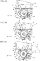
- FIG. 9A is a right side view showing the toner container in a situation, in which the lever is located at a first position, in the printer according to the embodiment of the present disclosure.
- FIG. 9B is a right side view showing the toner container in another situation, in which the lever is located at a second position, in the printer according to the embodiment of the present disclosure.
- FIG. 9C is a right side view showing the toner container in a further situation, in which the lever is located at a third position, in the printer according to the embodiment of the present disclosure.
- FIG. 9A is a right side view showing the toner container in a situation, in which the lever is located at a first position, in the printer according to the embodiment of the present disclosure.
- FIG. 9B is a right side view showing the toner container in another situation, in which the lever is located at a second position, in the printer according to the embodiment of the present disclosure.
- FIG. 9C is a right side view showing the toner container in a further situation, in which the lever
- FIG. 10A is a bottom perspective view showing the toner container in a situation, in which the lever is located at a first position, in the printer according to the embodiment of the present disclosure.
- FIG. 10B is a bottom perspective view showing the toner container in another situation, in which the lever is located at a second position, in the printer according to the embodiment of the present disclosure.
- FIG. 10C is a bottom perspective view showing the toner container in a further situation, in which the lever is located at a third position, in the printer according to the embodiment of the present disclosure.
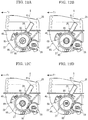
- FIG. 11A is a schematic diagram showing the toner container in a situation, in which a gripper of the lever engages with a stopper, in the printer according to the embodiment of the present disclosure.
- FIG. 11A is a schematic diagram showing the toner container in a situation, in which a gripper of the lever engages with a stopper, in the printer according to the embodiment of the present disclosure.
- FIG. 11B is a schematic diagram showing the toner container in an ongoing situation, in which the gripper of the lever is shifted from an engaging state with the stopper to a released state, in the printer according to the embodiment of the present disclosure.
- FIG. 11C is a schematic diagram showing the toner container in a situation, in which the engagement of the gripper of the lever with a stopper is released, in the printer according to the embodiment of the present disclosure.
- the gripper 61 of the lever 26 When the printer 1 is taken on market, as shown in FIG. 9A , the gripper 61 of the lever 26 is tilted forward and, as shown in FIG. 10A , the shutter 28 closes the discharge port 35 of the case main body 22. In addition, as shown in FIG. 11A , the gripper 61 of the lever 26 engages with the stopper 45, thereby restricting the turn of the lever 26. A position of the lever 26 at this moment is called as a "first position" .
- the shutter 28 connected with the lever 26 turns, too. Accordingly, as shown in FIG. 10C , the shutter 28 opens the discharge port 35 of the case main body 22, and then, the inside of the case main body 22 and the inside of the development device 12 are communicated with each other. It is therefore possible to supply the toner from the toner container 5 to the development device 12.
- the shutter 28 closes the discharge port 35 of the case main body 22. In such a situation, the toner container 5 may be pulled out from the printer main body 2.
- the toner container 5 by installing the toner container 5 to the printer main body 2 in the situation of the lever 26 located at the first position, it is possible to close the upper cover 6 in a situation, in which the shutter 28 closes the discharge port 35 of the case main body 22. Accordingly, it is possible to surely prevent the toner from leaking from the toner container 5 during transport and to take the toner container 5 combined with the printer main body 2 on market. Therefore, the specific packaging material for packing the toner container 5 is unnecessary, thereby decreasing a packaging cost.
- the embodiment is configured so that the gripper 61 of the lever 26 gets over the inclined parts 53 of the stopper 45, when the gripper 61 of the lever 26 shifts from an engagement state with the stopper45 to a release state. Therefore, it is possible to prevent the lever 26 turned once from the first position to the second position from going back to the first position again.
- the transmission coupling 66 is formed in a triangle shape in a side view and the drive coupling 90 attachably/detachably jointed to the transmission coupling 66 is formed in a triangle shape in a side view corresponding to the transmission coupling 66.
- the transmission coupling 66 may be formed in a roughly fan shape as shown in FIG. 12B , in a roughly arc shape as shown in FIG. 12C or in a rectangular shape as shown in FIG. 12D .
- the drive coupling 90 may be variously formed in a jointable shape with the corresponding to the transmission coupling66.
- the transmission coupling 66 and drive coupling 90 are differently formed according to eachdestination, it is possible to prevent the toner container 5 for one destination being installed to the printer main body 2 for another destination and to restrict failure caused by mistaken installation of the toner container 5.
- the configuration of the disclosure was described in case of applying the configuration of the disclosure to the upper cover 6.
- the configuration of the disclosure may be applied to a front cover, a side cover or another cover.
- lever 26 and shutter 28 may be formed in a body.
- the embodiment was described in a case where ideas of the disclosure are applied to the printer 1, as a furthermore embodiment, the ideas of the disclosure may be applied to another image forming apparatus except the printer 1, such as a copying machine, a facsimile or a multifunction machine.
Landscapes
- Physics & Mathematics (AREA)
- General Physics & Mathematics (AREA)
- Dry Development In Electrophotography (AREA)
- Electrophotography Configuration And Component (AREA)
Description
- This application is based on and claims the benefit of priority from Japanese Patent application No.
2012-124853 filed on May 31, 2012 - The present disclosure relates to an image forming apparatus and a toner case installed to the image forming apparatus.
- An electrographic image forming apparatus carries out the development process by supplying a toner (a developer) from a development device to an electrostatic latent image formed on the surface of a photosensitive drum or the like. The toner used in such development process is supplied from a toner case configured to be attachable and detachable to an apparatus main body of the image forming apparatus.
- The above-mentioned toner case includes a case main body having a discharge port discharging the toner and a shutter opening/closing the discharge port. For example, the shutter rotatably installed to the case main body and opening/closing the discharge port in accordance with the rotation is known. In such a technique, a locking member attached to the toner case locks the shutter in a closing state, thereby preventing the toner from leaking from the toner case during transport of the toner case.
- The above-mentioned technique is provided presupposing the transport of single toner case. In this case, the toner case is separately packed from the apparatus main body, and accordingly, the capacity and number of the packaging material are unnecessarily increased, thereby incurring an increase of a packaging cost.
- Moreover, in the imaging forming apparatus including the tone case configured as mentioned above, there is a fear that the toner case is installed, in a situation of the shutter closing the discharge port, to the apparatus main body by operation mistake of a worker, such as a user. However, a technique mentioned above does not take measures for solving the fear and it is difficult to prevent the operation mistake of the worker.
- In accordance with an embodiment of the present disclosure, an image forming apparatus includes a toner case, an apparatus main body and a cover. The toner case is configured to include a case main body having a discharge port configured to discharge a toner, a shutter configured to open/close the discharge port, and a lever connected with the shutter. To the apparatus main body, the toner case is attachably/detachably installed. The cover is openably/closably attached to the apparatus main body and configured to cover at least a part of the toner case. The lever is configured to be shifted to a first position in order to make the shutter close the discharge port and to allow the close of the cover without interfering with the cover, to a second position in order to make the shutter close the discharge port and to interfere with the cover, or to a third posit ion in order to make the shutter open the discharge port and to allow the close of the cover without interfering with the cover.
- Furthermore, in accordance with an embodiment of the present disclosure, a toner case is attachably/detachably installed to an apparatus main body of an image forming apparatus and covered by a cover openably/closably attached to the apparatus main body. The toner case includes a case main body, a shutter and a lever. The case main body has a discharge port configured to discharge a toner. The shutter is configured to open/close the discharge port. The lever is configured to connect with the shutter and to be shifted to a first position in order to make the shutter close the discharge port and to allow the close of the cover without interfering with the cover, to a second position in order to make the shutter close the discharge port and to interfere with the cover, or to a third position in order to make the shutter open the discharge port and to allow the close of the cover without interfering with the cover.
- The above and other objects, features, and advantages of the present disclosure will become more apparent from the following description when taken in conjunction with the accompanying drawings in which a preferred embodiment of the present disclosure is shown by way of illustrative example.
-
-
FIG. 1 is a schematic diagram schematically showing a printer according to an embodiment of the present disclosure. -
FIG. 2 is a perspective view showing the printer in a situation, in which an upper cover is opened, according to the embodiment of the present disclosure. -
FIG. 3 is a right top perspective view showing a toner container in the printer according to the embodiment of the present disclosure. -
FIG. 4 is a back perspective sectional view showing the toner container in the printer according to the embodiment of the present disclosure. -
FIG. 5 is an exploded perspective view showing the toner container in the printer according to the embodiment of the present disclosure. -
FIG. 6 is a front right perspective view showing the toner container in a situation, in which a lever is detached from a case main body, in the printer according to the embodiment of the present disclosure. -
FIG. 7 is a right side view showing the toner container in the printer according to the embodiment of the present disclosure. -
FIG. 8 is a perspective view showing the printer in a situation, in which the upper cover is closed, according to the embodiment of the present disclosure. -
FIG. 9A is a right side view showing the toner container in a situation, in which the lever is located at a first position, in the printer according to the embodiment of the present disclosure.FIG. 9B is a right side view showing the toner container in another situation, in which the lever is located at a second position, in the printer according to the embodiment of the present disclosure.FIG. 9C is a right side view showing the toner container in a further situation, in which the lever is located at a third position, in the printer according to the embodiment of the present disclosure. -
FIG. 10A is a bottom perspective view showing the toner container in a situation, in which the lever is located at the first position, in the printer according to the embodiment of the present disclosure.FIG. 10B is a bottom perspective view showing the toner container in another situation, in which the lever is located at the second position, in the printer according to the embodiment of the present disclosure.FIG. 10C is a bottom perspective view showing the toner container in a further situation, in which the lever is located at the third position, in the printer according to the embodiment of the present disclosure. -
FIG. 11A is a schematic diagram showing the toner container in a situation, in which a gripper of the lever engages with a stopper, in the printer according to the embodiment of the present disclosure.FIG. 11B is a schematic diagram showing the toner container in a another situation, in which the gripper of the lever is going to be shifted from an engaging state with the stopper to a released state, in the printer according to the embodiment of the present disclosure.FIG. 11C is a schematic diagram showing the toner container in a further situation, in which the engagement of the gripper of the lever with a stopper is released, in the printer according to the embodiment of the present disclosure. -
FIG. 12A is a side view showing a transmission coupling in the printer according to the embodiment of the present disclosure.FIG. 12B is a side view showing a roughly fan-formed transmission coupling in the printer according to another embodiment of the present disclosure.FIG. 12C is a side view showing a roughly arc-formed transmission coupling in the printer according to a further embodiment of the present disclosure.FIG. 12D is a side view showing a rectangle-formed transmission coupling in the printer according to a furthermore embodiment of the present disclosure. - With reference to
FIG. 1 , the entire structure of an electrographic printer (an image forming apparatus) 1 will be described.FIG. 1 is a schematic diagram schematically showing the printer according to an embodiment of the present disclosure. Hereinafter, it will be described so that the front side of the printer 1 is positioned at the left-hand side ofFIG. 1 . - The printer 1 includes a box-formed printer main body 2 (apparatus main body). To a lower part of the printer
main body 2, a sheet feeding cartridge 3 configured to store sheets (not shown) is installed and, on the top surface of the printermain body 2, an ejectingtray 4 is mounted. To the upper front part of the printermain body 2, atoner container 5 as a toner case is attachably/detachably installed and, above thetoner container 5, an upper cover 6(cover) is openably/closably attached. - To an upper part of the printer
main body 2, an exposure device 7 composed of a laser scanning unit (LSU) is installed below thesheet ejecting tray 4. Below the exposure device 7, animage forming unit 8 is installed. To theimage forming unit 8, aphotosensitive drum 10 as an image carrier is rotatably installed. Around thephotosensitive drum 10, acharger 11, adevelopment device 12, atransfer roller 13 and acleaning device 14 are located along a rotating direction (refer to arrow X inFIG. 1 ) of thephotosensitive drum 10. - Inside the printer
main body 2, asheet conveying path 15 is arranged. At an upper stream end of the conveyingpath 15, asheet feeder 16 is positioned. At an intermediate stream part of the conveyingpath 15, a transferringunit 17 constructed of thephotosensitive drum 10 andtransfer roller 13 is positioned. At a lower stream part of the conveyingpath 15, a fixingdevice 18 is positioned. At a lower stream end of the conveyingpath 15, asheet ejecting unit 20 is positioned. Below the conveyingpath 15, aninversion path 21 for duplex printing is arranged. - Next, the operation of forming an image by the printer 1 having such a configuration will be described.
- When the power is supplied to the printer 1, various parameters are initialized and initial determination, such as temperature determination of the fixing
device 18, is carried out. Subsequently, in the printer 1, when image data is inputted and a printing start is directed from a computer or the like connected with the printer 1, image forming operation is carried out as follows. - First, the surface of the
photosensitive drum 10 is electrically charged by thecharger 11. Then, exposure corresponding to the image data on thephotosensitive drum 10 is carried out by a laser (refer to two-dot chain line P inFIG. 1 ) from the exposure device 7, thereby forming an electrostatic latent image on the surface of thephotosensitive drum 10. Subsequently, the electrostatic latent image is developed to a toner image with a toner (a developer) in thedevelopment device 12. - On the other hand, a sheet fed from the sheet feeding cartridge 3 by the
sheet feeder 16 is conveyed to the transferringunit 17 in a suitable timing for the above-mentioned image forming operation, and then, the toner image on thephotosensitive drum 10 is transferred onto the sheet in the transferringunit 17. The sheet with the transferred toner image is conveyed to a lower stream on the conveyingpath 15 to go forward to the fixingdevice 18, and then, the toner image is fixed on the sheet in the fixingdevice 18. The sheet with the fixed toner image is ejected from thesheet ejecting unit 20 to thesheet ejecting tray 4. Toner remained on thephotosensitive drum 10 is collected by thecleaning device 14. - Next, with reference to
FIGS. 2-7 , thetoner container 5 will be described in detail.FIG. 2 is a perspective view showing the printer in a situation, in which the upper cover is opened, according to the embodiment of the present disclosure.FIG. 3 is a right top perspective view showing the toner container in the printer according to the embodiment of the present disclosure.FIG. 4 is a back perspective sectional view showing the toner container in the printer according to the embodiment of the present disclosure.FIG. 5 is an exploded perspective view showing the toner container in the printer according to the embodiment of the present disclosure.FIG. 6 is a front right perspective view showing the toner container in a situation, in which a lever is detached from a case main body, in the printer according to the embodiment of the present disclosure.FIG. 7 is a right side view showing the toner container in the printer according to the embodiment of the present disclosure. - Arrow Fr suitably put on each figure indicates the front side of the printer 1 (
FIG. 8 and other figure is illustrated in similar way). BecauseFIG. 4 is the back perspective sectional view, the left-hand and right-hand sides of the figure are converse to the actual left-hand and right-hand sides. That is, the right-hand side illustrated inFIG. 4 is the left-hand side of thetoner container 5 and the left-hand side illustrated inFIG. 4 is the right-hand side of thetoner container 5. - As shown in
FIG. 2 , thetoner container 5 is located below theupper cover 6. Thetoner container 5 is also attachably/detachably installed at a top surface of the development device 12 (refer toFIG. 1 ) to the printermain body 2. As shown inFIG. 3 , thetoner container 5 is formed in an extended-shape in left and right directions or a horizontal direction. - As shown in
FIG. 4 , thetoner container 5 includes a box-formed casemain body 22 with an opened top surface, a conveying screw (a rotating member) 23, a stirring paddle (another rotating member) 24, a coveringbody 25, alever 26, a transmittingmember 27 and ashutter 28. The conveyingscrew 23 is installed to a lower rear part of the casemain body 22. The stirringpaddle 24 is installed near a center part of the casemain body 22. The coveringbody 25 covers the top surface of the casemain body 22. Thelever 26 is attached to a right end of the casemain body 22. The transmittingmember 27 is placed on the right end of the casemain body 22 together with thelever 26. Theshutter 28 is attached on a right bottom end of the casemain body 22. The transmittingmember 27 is omitted inFIGS. 6 and7 . - The case
main body 22 is formed in an extended-shape in the horizontal direction to contain the toner. On aleft end wall 30 of the casemain body 22, atoner filling port 31 is formed and thetoner filling port 31 is closed by acap 32. On the circumference of a top end of the casemain body 22, a mainbody side flange 33 is formed. - At the right bottom end of the case
main body 22, a cylinder-formeddischarge duct 34 is protruded to a right direction and, in a right end of thedischarge duct 34, anaperture 36 is formed. In a bottom of thedischarge duct 34, adischarge port 35 discharging the toner is bored. On the circumference of a lower part of thedischarge duct 34, a sealingmember 37 is attached and, in the sealingmember 37, acommunication port 38 is bored at a correspondent position to thedischarge port 35. - As shown in
FIG. 5 , at the center of aright end wall 40 of the casemain body 22, a cylinder-formedboss 42 having acommunication hole 41 is protruded to a right direction (an outside direction). On a right surface (an external surface) of theright end wall 40 of the casemain body 22, a restrainrib 43 is protruded to an upper backward direction of theboss 42. Below the first restrainrib 43, aprotrusion 44 is formed. - As shown in
FIG. 6 and other figure, on the right surface (the external surface) of theright end wall 40 of the casemain body 22, astopper 45 is protruded to an upper forward direction of theboss 42. Thestopper 45 is connected with the restrainrib 43 by a connectingrib 46. - The
stopper 45 includes acurved piece 47, anengagement piece 48, areinforcement piece 49 and aconnection piece 50. Thecurved piece 47 curves in an arc-liked shape around theboss 42. Theengagement piece 48 is connected with a rear side of an upper part of thecurved piece 47. Thereinforcement piece 49 is located above theengagement piece 48. Theconnection piece 50 connects theengagement piece 48 andreinforcement piece 49. On a lower part and an intermediate part in upper and lower directions or a vertical direction of thecurved piece 47,support pieces 51 are protruded backward. Theengagement piece 48 is formed in a U-shape laid on side to include a pair of upper andlower engagement plates 52. In thereinforcement piece 49 andengagement plates 52,inclined parts 53 are respectively formed. Eachinclined part 53 inclines so that protruded length from the right surface of theright end wall 40 of the casemain body 22 is gradually lengthen from a front side to a rear side. - As shown in
FIG. 4 and other figure, the conveyingscrew 23 is formed in an extended-shape in the horizontal direction and installed to the casemain body 22 in a rotatable state. The conveyingscrew 23 includes a bar-formedrotating shaft 54 and aspiral fin 55 concentrically mounted on the circumference of therotating shaft 54. A left end of therotating shaft 54 is pivotally supported by theleft end wall 30 of the casemain body 22. Right side parts of therotating shaft 54 andspiral fin 55 are inserted into thedischarge duct 34. A right end of therotating shaft 54 protrudes from thedischarge duct 34 via theaperture 36 to the right direction and, on the protruding part, a conveyinggear 56 is fixedly attached. - The stirring
paddle 24 is located above and in front of the conveyingscrew 23 and formed in an extended-shape in the horizontal direction. The stirringpaddle 24 is installed to the casemain body 22 in a rotatable state. The stirringpaddle 24 includes a supportingframe 57 formed in a frame plate-liked shape and a sheet-formedstirring fin 58 supported by the supportingframe 57. Left and right ends (both horizontal ends) of the supportingframe 57 are pivotally supported by theleft end wall 30 andright end wall 40 of the casemain body 22. The stirringfin 58 is formed out of plastic sheet, e.g. lumirror. As shown inFIG. 4 , one side of the stirringfin 58 is fixedly attached onto the supportingframe 57 along the horizontal direction. - On a bottom end of the covering
body 25, a coveringbody side flange 59 is formed in the correspondent form to the main body side flange 33 of the casemain body 22. The mainbody side flange 33 and coveringbody side flange 59 are ultrasonic-welded together so that the casemain body 22 and coveringbody 25 are unified. - As shown in
FIG. 7 , thelever 26 includes a levermain body 60 with a circular profile in a side view. The levermain body 60 is attached on the circumference of theboss 42 arranged on the right surface of theright end wall 40 of the casemain body 22. Thereby, thelever 26 is rotatably supported to the casemain body 22 so that thelever 26 turns along the right surface of theright end wall 40 of the casemain body 22. On an upper part of the levermain body 60, agripper 61 is protruded to the outside in the radial direction. A top end of thegripper 61 extends to the right side of the coveringbody 25. As shown inFIG. 6 , thegripper 61 is hollow and, in a lower front part of thegripper 61, adepression 62 is formed. On the levermain body 60, aprotrusion piece 63 is protruded to the outside in the radial direction at a front side of thegripper 61. On the circumference of a lower rear part of the levermain body 60, lever side gear 64 (refer toFIG. 7 ) is formed. - As shown in
FIG. 5 and other figure, the transmittingmember 27 includes a disc-formed transmitting membermain body 65. On a right surface (an external surface) of the transmitting membermain body 65, atransmission coupling 66 is protruded in the form of a triangle shape in a side view. Thetransmission coupling 66 is attachably/detachably jointed to a drive coupling 90 (refer toFIG. 9C ) connected with a driver 91 (refer toFIG. 9C ), such a motor. Accordingly, when thedriver 91 makes the drive coupling rotates, this rotation is transmitted to the transmittingmember 27, and then, the transmittingmember 27 rotates. - As shown in
FIG. 5 and other figure, on a left surface (an internal surface) of the transmitting membermain body 65, aninsertion piece 67 is protruded. Theinsertion piece 67 is inserted into thecommunication hole 41 bored in theboss 42 of the casemain body 22, and then, jointed to the supportingframe 57 of the stirringpaddle 24. Accordingly, when the transmittingmember 27 rotates, this rotation is transmitted to the stirringpaddle 24, and then, the stirringpaddle 24 rotates so that the toner in the casemain body 22 is stirred and conveyed to the conveyingscrew 23. - On the circumference of the transmitting member
main body 65, atransmission gear 68 is formed. Thetransmission gear 68 meshes with the conveyinggear 56 of the conveyingscrew 23. Accordingly, when the transmittingmember 27 rotates, this rotation is transmitted to the conveyingscrew 23, and then, the conveyingscrew 23 rotates so that the toner in the casemain body 22 is discharged from thedischarge port 35 and filled into the development device 12 (refer toFIG. 1 ). In the outside part of the transmitting membermain body 65 in the radial direction, anaperture 69 curved in an arc-liked shape is bored. - The
shutter 28 is formed in a roughly cylinder-liked shape and rotatably installed to the circumference of thedischarge duct 34 of the casemain body 22. In a lower surface of theshutter 28, adischarge aperture 70 is bored. As shown inFIG. 7 , on theshutter 28, a roughly fan-formedguiding piece 71 is protruded. In the guidingpiece 71, an arc-formedguiding hole 72 is formed and, with the guidinghole 72, theprotrusion 44 of the casemain body 22 engages. - As shown in
FIG. 4 and other figure, in theshutter 28, a cylinder-formedbearing 73 is formed and, into thebearing 73, the right end of therotating shaft 54 of conveyingscrew 23 is pivotally supported. On the right side of thebearing 73, agear box 74 is attached and thegear box 74 houses the conveyinggear 56. As shown inFIG. 5 and other figure, in thegear box 74, acommunication aperture 75 is formed so that the conveyinggear 56 can be housed in thegear box 74 via thecommunication aperture 75. - The
shutter 28 is provided with ashutter side gear 76. Theshutter side gear 76 meshes with thelever side gear 64 of thelever 26. Thereby, thelever 26 is connected to theshutter 28 so that theshutter 28 turns in the opposite direction to thelever 26 accompanying to the turn of thelever 26. On the right end of theshutter 28, anelliptic locking piece 77 is attached. In a lower part of theshutter 28, apressing protrusion 78 is formed at the right side of thedischarge aperture 70. - Next, with reference to
FIG. 8 , theupper cover 6 will be described.FIG. 8 is a perspective view showing the printer in a situation, in which the upper cover is closed, according to the embodiment of the present disclosure. Hereinafter, the terms of upper and lower, left and right, and front and back (rear) are used so as to indicate the directions in view of the closed upper cover (refer toFIG. 8 ). - As shown in
FIG. 8 , theupper cover 6 includes anupper plate 81 and afront plate 82 and is formed with a roughly L-shaped section. Theupper plate 81 covers an upper surface side of thetoner container 5 and thefront plate 82 covers a front surface side of thetoner container 5. Thefront plate 82 is bended downward from a front end of theupper plate 81. - A rear end of the
upper plate 81 is attached to the printermain body 2 via a hinge (not shown) so that theupper cover 6 opens or closes to the printermain body 2 by turning around the hinge as a fulcrum. At an upper surface side of theupper plate 81, an operation unit (not shown) constructed by a liquid crystal display (LCD) or an electric luminescent display (ELD) is provided. According to handling of keys or buttons arranged to the operation unit by a user, the various functions of the printer 1 are actualized. - On an inside surface (a lower surface in the embodiment) of the
upper plate 81, abase part 83 in a rectangular shape in a side view is protruded and, to a lower surface of thebase part 83, a trapezoid-formedprotrusion 84 is attached. On a front end of theprotrusion 84, a first guidingface 85 inclined below and backward is formed and, on a rear end of theprotrusion 84, asecond guiding face 86 inclined below and forward is formed. - In the above-mentioned structure, an operation of the
lever 26 will be described mainly with reference toFIG. 9A to FIG. 11C .FIG. 9A is a right side view showing the toner container in a situation, in which the lever is located at a first position, in the printer according to the embodiment of the present disclosure.FIG. 9B is a right side view showing the toner container in another situation, in which the lever is located at a second position, in the printer according to the embodiment of the present disclosure.FIG. 9C is a right side view showing the toner container in a further situation, in which the lever is located at a third position, in the printer according to the embodiment of the present disclosure.FIG. 10A is a bottom perspective view showing the toner container in a situation, in which the lever is located at a first position, in the printer according to the embodiment of the present disclosure.FIG. 10B is a bottom perspective view showing the toner container in another situation, in which the lever is located at a second position, in the printer according to the embodiment of the present disclosure.FIG. 10C is a bottom perspective view showing the toner container in a further situation, in which the lever is located at a third position, in the printer according to the embodiment of the present disclosure.FIG. 11A is a schematic diagram showing the toner container in a situation, in which a gripper of the lever engages with a stopper, in the printer according to the embodiment of the present disclosure.FIG. 11B is a schematic diagram showing the toner container in an ongoing situation, in which the gripper of the lever is shifted from an engaging state with the stopper to a released state, in the printer according to the embodiment of the present disclosure.FIG. 11C is a schematic diagram showing the toner container in a situation, in which the engagement of the gripper of the lever with a stopper is released, in the printer according to the embodiment of the present disclosure. - When the printer 1 is taken on market, as shown in
FIG. 9A , thegripper 61 of thelever 26 is tilted forward and, as shown inFIG. 10A , theshutter 28 closes thedischarge port 35 of the casemain body 22. In addition, as shown inFIG. 11A , thegripper 61 of thelever 26 engages with thestopper 45, thereby restricting the turn of thelever 26. A position of thelever 26 at this moment is called as a "first position" . - Thus, when the
upper cover 6 is shifted to a closing state in a situation, in which thelever 26 is located at the first position, as shown inFIG. 8 , the first guidingface 85 of theprotrusion 84 of theupper cover 6 faces to thegripper 61 of thelever 26. At that moment, because thegripper 61 of thelever 26 andprotrusion 84 of theupper cover 6 are not interfered with each other, the close of theupper cover 6 is allowed. - On the other hand, when the printer 1 is used, as indicated by arrow A in
FIG. 9A , a worker, such as a user or a serviceman, pushes thegripper 61 of thelever 26 backward. By this push, as shown inFIG. 11B , thegripper 61 of thelever 26 is shifted backward along theinclined parts 53 of thestopper 45. At that moment, the depression 62 (refer toFIG. 6 and other figures) formed on thegripper 61 of thelever 26 engages with thelower engagement plate 52, thereby slightly decreasing a necessary pushing force for making thelever 26 turned backward. InFIGS. 11A, 11B and 11C , only theinclined part 53 of theupper engagement plate 52 is shown. - When the
gripper 61 of thelever 26 is pushed further backward, as shown inFIG. 11C , thegripper 61 of thelever 26 gets over theinclined parts 53 of thestopper 45. Thereby, as shown inFIG. 9B , the engagement of thegripper 61 of thelever 26 with thestopper 45 is released and thelever 26 turns to a slighter back position than the first position. The position of thelever 26 at this time is called as a "second position". Thus, when thelever 26 turns from the first position to the second position, theshutter 28 slightly turns accompanying to this. However, as shown inFIG. 10B , theshutter 28 still closes thedischarge port 35 of the casemain body 22. - Therefore, even if the close of the
upper cover 6 is tried in another situation, in which thelever 26 is located at the second position, as indicated one-dot chain line inFIG. 8 , because thegripper 61 of thelever 26 andprotrusion 84 of theupper cover 6 are interfered with each other, the close of theupper cover 6 is prevented. - Next, as indicated by arrow B in
FIG. 9B , when the worker pushes thelever 26 furthermore backward, as shown inFIG. 9C , thelever 26 turns to a further back position than the second position. The position of thelever 26 at this time is called as a "third position". Thus, when theupper cover 6 is shifted to the closing state in a further situation, in which thelever 26 is located at the third position, as indicated two-dot chain line inFIG. 8 , the second guidingface 86 of theprotrusion 84 of theupper cover 6 faces to thegripper 61 of thelever 26. At that moment, because thegripper 61 of thelever 26 andprotrusion 84 of theupper cover 6 are not interfered with each other, the close of theupper cover 6 is allowed. - Thus, when the
lever 26 turns to the third position, as indicated by arrow C inFIG. 9B , theshutter 28 connected with thelever 26 turns, too. Accordingly, as shown inFIG. 10C , theshutter 28 opens thedischarge port 35 of the casemain body 22, and then, the inside of the casemain body 22 and the inside of thedevelopment device 12 are communicated with each other. It is therefore possible to supply the toner from thetoner container 5 to thedevelopment device 12. - When the
toner container 5 is replaced, by returning thelever 26 to the second position, theshutter 28 closes thedischarge port 35 of the casemain body 22. In such a situation, thetoner container 5 may be pulled out from the printermain body 2. - As mentioned above, in the embodiment, by installing the
toner container 5 to the printermain body 2 in the situation of thelever 26 located at the first position, it is possible to close theupper cover 6 in a situation, in which theshutter 28 closes thedischarge port 35 of the casemain body 22. Accordingly, it is possible to surely prevent the toner from leaking from thetoner container 5 during transport and to take thetoner container 5 combined with the printermain body 2 on market. Therefore, the specific packaging material for packing thetoner container 5 is unnecessary, thereby decreasing a packaging cost. - In addition, when the printer 1 is used, if the
toner container 5 is installed to the printermain body 2 in the other situation of thelever 26 located at the second position, thegripper 61 of thelever 26 andprotrusion 84 of theupper cover 6 are interfered with each other, thereby preventing the close of theupper cover 6. Therefore, it is possible to make the worker aware that theupper cover 6 is going to be closed by mistake while thedischarge port 35 of the casemain body 22 is closed, and then, to prevent the following operation mistake by the worker. Moreover, when the printer 1 is used, if thelever 26 is shifted to the third position, it is possible to close theupper cover 6 in a situation, in which theshutter 28 opens thedischarge port 35 of the casemain body 22, and then, to carry out the operation of forming the image. - Thus, by switching the position of the
lever 26 to the firstposition, secondpositionorthirdposition, itispossible to surely prevent the toner from leaking from thetoner container 5 during the transport, to decrease a packaging cost and to prevent the operation mistake by the worker. - Moreover, in the situation of the
lever 26 located at the first position, because thegripper 61 of thelever 26 engages with thestopper 45 to restrict the turn of thelever 26, it is possible to surely maintain the situation of thelever 26 in the first position. Accordingly, it is possible to prevent thelever 26 from turning from the first position to the third position over the second position during the transport of the printer 1 and to prevent theshutter 28 from opening thedischarge port 35 of the casemain body 22. Therefore, it is possible to prevent failure as leakage of the toner from thetoner container 5 during the transport of the printer 1. - In addition, the embodiment is configured so that the
gripper 61 of thelever 26 gets over theinclined parts 53 of thestopper 45, when thegripper 61 of thelever 26 shifts from an engagement state with the stopper45 to a release state. Therefore, it is possible to prevent thelever 26 turned once from the first position to the second position from going back to the first position again. - Furthermore, it is possible to surely maintain, while the
upper cover 6 is closed, the situation of thelever 26 located at the first position or the third position by making the first guidingface 85 or second guidingface 86 formed on theprotrusion 84 of theupper cover 6 facing to thegripper 61 of thelever 26. - In the embodiment, as shown in
FIG. 12A , thetransmission coupling 66 is formed in a triangle shape in a side view and thedrive coupling 90 attachably/detachably jointed to thetransmission coupling 66 is formed in a triangle shape in a side view corresponding to thetransmission coupling 66. However, in other embodiments, thetransmission coupling 66 may be formed in a roughly fan shape as shown inFIG. 12B , in a roughly arc shape as shown inFIG. 12C or in a rectangular shape as shown inFIG. 12D . In these cases, thedrive coupling 90 may be variously formed in a jointable shape with the corresponding to the transmission coupling66. In particular, if thetransmission coupling 66 and drivecoupling 90 are differently formed according to eachdestination, it is possible to prevent thetoner container 5 for one destination being installed to the printermain body 2 for another destination and to restrict failure caused by mistaken installation of thetoner container 5. - The embodiment was described in case of applying the configuration of the disclosure to the
upper cover 6. However, in another embodiment, the configuration of the disclosure may be applied to a front cover, a side cover or another cover. - The embodiment was described in case of forming the
lever 26 andshutter 28 separately. However, in a further embodiment, thelever 26 andshutter 28 may be formed in a body. - Although the embodiment was described in a case where ideas of the disclosure are applied to the printer 1, as a furthermore embodiment, the ideas of the disclosure may be applied to another image forming apparatus except the printer 1, such as a copying machine, a facsimile or a multifunction machine.
Claims (15)
- An image forming apparatus (1) comprising:a toner case (5) configured to include a case main body (22) having a discharge port (35) configured to discharge a toner, a shutter (28) configured to open/close the discharge port (35), and a lever (26) connected with the shutter (28);an apparatus main body (2) to which the toner case (5) is attachably/detachably installed; anda cover (6) openably/closably attached to the apparatus main body (2) and configured to cover at least a part of the toner case (5),the image forming apparatus (1) being characterized in that the lever (26) is configured to be shifted to a first position in order to make the shutter (28) close the discharge port (35) and to allow the close of the cover (6) without interfering with the cover (6), to a second position in order to make the shutter (28) close the discharge port (35) and to prevent the close of the cover (6) by interfering with the cover (6), or to a third position in order to make the shutter (28) open the discharge port (35) and to allow the close of the cover (6) without interfering with the cover (6), and the lever (26) is supported to the case main body (22).
- The image forming apparatus (1) according to claim 1, wherein, on an external surface of the case main body (22), a stopper (45) is protruded,
the lever (26) is configured to turn along the external surface of the case main body (22) from the first position to the third position over the second position,
the lever (26) in a situation of being located at the first position is configured to engage with the stopper (45) so that turn of the lever (26) is restricted, and
when the lever (26) in the situation of being located at the first position is pushed toward the second position, the engagement of the lever (26) with the stopper (45) is released so that the lever (26) is permitted to turn to the second position. - The image forming apparatus (1) according to claim 2, wherein the stopper (45) includes an inclined part (53) formed so that a protruded length from the external surface of the case main body (22) is gradually lengthen from a side of the first position to another side of the second position, and
when the lever (26) is shifted from an engaging state with the stopper (45) to a released state, the lever (26) gets over the inclined part (53). - The image forming apparatus (1) according to claim 3, wherein the stopper (45) includes:a curved piece (47) configured to curve in an arc-liked shape; andan engagement piece (48) configured to connect with the curved piece (47), andthe engagement piece (48) is further configured to have the inclined part (53).
- The image forming apparatus (1) according to claim 4, wherein the stopper (45) further includes a reinforcement piece (49) configured to connect with the engagement piece (48) and to have another inclined part (53) similar to the inclined part (53).
- The image forming apparatus (1) according to any one of claims 2 to 5, wherein the lever (26) includes:a lever main body (60) installed to the case main body (22); anda gripper (61) protruded on the lever main body (60), andin the situation of the lever (26) located at the first position, the gripper (61) engages with the stopper (45).
- The image forming apparatus (1) according to claim 6, wherein the gripper (61) includes a depression (62), and
when the lever (26) in the situation of being located at the first position is pushed toward the second position, the depression (62) engages with the stopper (45). - The image forming apparatus (1) according to any one of claims 1 to 7, wherein the toner case (5) includes one or more rotating members (23, 24) rotatably attached to the case main body (22) and a transmitting member (27) being connected with the rotating members (23, 24) and having a transmission coupling (66),
the apparatus main body (2) includes a drive coupling (90) attachably/detachably jointed to the transmission coupling (66) and a driver (91) making the drive coupling (90) rotate, and
the transmission coupling (66) and drive coupling (90) are differently formed according to each destination. - The image forming apparatus (1) according to claim 8, wherein the rotating members (23, 24) include:a stirring paddle (24) configured to stir the toner in the case main body (22), anda conveying screw (23) configured to discharge the toner in the case main body (22) from the discharge port (35).
- The image forming apparatus (1) according to any one of claims 1 to 9, wherein, on an inside surface of the cover (6), a protrusion (84) is formed, and
the protrusion (84) includes:a first guiding face (85) configured to face the lever (26) when the cover (6) is closed in a situation of the lever (26) located at the first position; anda second guiding face (86) configured to face the lever (26) when the cover (6) is closed in another situation of the lever (26) located at the third position. - A toner case (5) attachably/detachably installed to an apparatus main body (2) of an image forming apparatus (1) and covered by a cover (6) openably/closably attached to the apparatus main body (2) comprising:a case main body (22) having a discharge port (35) configured to discharge a toner;a shutter (28) configured to open/close the discharge port (35); anda lever (26) configured to connect with the shutter (28), the toner case (5) being characterized in that the lever (26) is configured to be shifted to a first position in order to make the shutter (28) close the discharge port (35) and to allow the close of the cover (6) without interfering with the cover (6), to a second position in order to make the shutter (28) close the discharge port (35) and to prevent the close of the cover (6) by interfering with the cover (6), or to a third position in order to make the shutter (28) open the discharge port (35) and to allow the close of the cover (6) without interfering with the cover (6), and the lever (26) is supported to the case main body (22).
- The toner case (5) according to claim 11, wherein, on an external surface of the case main body (22), a stopper (45) is protruded,
the lever (26) is configured to turn along the external surface of the case main body (22) from the first position to the third position over the second position,
the lever (26) in a situation of being located at the first position is configured to engage with the stopper (45) so that turn of the lever (26) is restricted, and
when the lever (26) in the situation of being located at the first position is pushed toward the second position, the engagement of the lever (26) with the stopper (45) is released so that the lever (26) is permitted to turn to the second position. - The toner case (5) according to claim 12, wherein the stopper (45) includes an inclined part (53) formed so that a protruded length from the external surface of the case main body (22) is gradually lengthen from a side of the first position to another side of the second position, and
when the lever (26) is shifted from an engaging state with the stopper (45) to a released state, the lever (26) gets over the inclined part (53). - The toner case (5) according to any one of claims 11 to 13, further comprising a rotating member (23, 24) rotatably attached to the case main body (22) and a transmitting member (27) being connected with the rotating member (23, 24) and having a transmission coupling (66),
wherein the apparatus main body (2) includes a drive coupling (90) attachably/detachably jointed to the transmission coupling (66) and a driver (91) making the drive coupling (90) rotate, and
the transmission coupling (66) and drive coupling (90) are differently formed according to each destination. - The toner case (5) according to any one of claims 11 to 14, wherein, on an inside surface of the cover (6), a protrusion (84) is formed, and
the protrusion (84) includes:a first guiding face (85) configured to face the lever (26) when the cover (6) is closed in a situation of the lever (26) located at the first position; anda second guiding face (86) configured to face the lever (26) when the cover (6) is closed in another situation of the lever (26) located at the third position.
Applications Claiming Priority (1)
| Application Number | Priority Date | Filing Date | Title |
|---|---|---|---|
| JP2012124853A JP5568597B2 (en) | 2012-05-31 | 2012-05-31 | Image forming apparatus and toner container |
Publications (3)
| Publication Number | Publication Date |
|---|---|
| EP2669747A2 EP2669747A2 (en) | 2013-12-04 |
| EP2669747A3 EP2669747A3 (en) | 2016-09-21 |
| EP2669747B1 true EP2669747B1 (en) | 2017-12-27 |
Family
ID=48463816
Family Applications (1)
| Application Number | Title | Priority Date | Filing Date |
|---|---|---|---|
| EP13168471.4A Active EP2669747B1 (en) | 2012-05-31 | 2013-05-21 | Image forming apparatus and toner case |
Country Status (4)
| Country | Link |
|---|---|
| US (1) | US8995885B2 (en) |
| EP (1) | EP2669747B1 (en) |
| JP (1) | JP5568597B2 (en) |
| CN (1) | CN103454879B (en) |
Families Citing this family (16)
| Publication number | Priority date | Publication date | Assignee | Title |
|---|---|---|---|---|
| US9207571B2 (en) * | 2012-01-31 | 2015-12-08 | Kyocera Document Solutions Inc. | Image forming apparatus and toner case |
| JP5722277B2 (en) * | 2012-05-31 | 2015-05-20 | 京セラドキュメントソリューションズ株式会社 | Image forming apparatus and toner container |
| JP5953287B2 (en) * | 2013-11-28 | 2016-07-20 | 京セラドキュメントソリューションズ株式会社 | Image forming apparatus |
| JP6234293B2 (en) | 2014-03-25 | 2017-11-22 | キヤノン株式会社 | Image forming apparatus |
| JP6173271B2 (en) * | 2014-07-30 | 2017-08-02 | 京セラドキュメントソリューションズ株式会社 | Toner container and image forming apparatus |
| JP6304117B2 (en) * | 2015-04-27 | 2018-04-04 | 京セラドキュメントソリューションズ株式会社 | Developer replenishing device, developing device including the same, image forming apparatus, developer containing container mounted on developer replenishing device |
| JP6390564B2 (en) * | 2015-09-11 | 2018-09-19 | 京セラドキュメントソリューションズ株式会社 | Image forming apparatus |
| JP6686402B2 (en) | 2015-12-08 | 2020-04-22 | 株式会社リコー | Lock lever structure, unit, image forming apparatus |
| JP6711672B2 (en) * | 2016-04-05 | 2020-06-17 | キヤノン株式会社 | Image forming device |
| JP6658396B2 (en) | 2016-08-10 | 2020-03-04 | 京セラドキュメントソリューションズ株式会社 | Image forming device |
| GB2569258A (en) | 2016-09-30 | 2019-06-12 | Canon Kk | Toner cartridge and toner supply mechanism |
| JP6638640B2 (en) * | 2016-12-22 | 2020-01-29 | 京セラドキュメントソリューションズ株式会社 | Toner container and image forming apparatus |
| JP7069948B2 (en) * | 2018-03-28 | 2022-05-18 | 京セラドキュメントソリューションズ株式会社 | Toner container and image forming device |
| JP7230527B2 (en) | 2019-01-22 | 2023-03-01 | 京セラドキュメントソリューションズ株式会社 | Toner container and image forming apparatus |
| GB201903438D0 (en) * | 2019-03-13 | 2019-04-24 | Ricoh Co Ltd | Device for controlling access to containers for dispensing printing material |
| JP7527843B2 (en) * | 2020-05-22 | 2024-08-05 | キヤノン株式会社 | Image forming system |
Family Cites Families (16)
| Publication number | Priority date | Publication date | Assignee | Title |
|---|---|---|---|---|
| JP3320285B2 (en) * | 1995-10-26 | 2002-09-03 | キヤノン株式会社 | Toner supply container |
| JP3672067B2 (en) * | 1998-01-20 | 2005-07-13 | 株式会社リコー | Image forming apparatus |
| JP3517610B2 (en) * | 1999-07-28 | 2004-04-12 | 京セラミタ株式会社 | Image forming unit and image forming apparatus |
| JP4034072B2 (en) * | 2002-01-10 | 2008-01-16 | シャープ株式会社 | Toner cartridge and packing method thereof |
| JP3854893B2 (en) * | 2002-04-25 | 2006-12-06 | キヤノン株式会社 | Developer container |
| CN100501603C (en) * | 2005-05-11 | 2009-06-17 | 兄弟工业株式会社 | Process cartridge, main body cartridge, image carrier body cartridge, developing cartridge, toner cartridge, and image forming apparatus |
| JP4701830B2 (en) * | 2005-05-11 | 2011-06-15 | ブラザー工業株式会社 | Process cartridge and image forming apparatus |
| JP2008116479A (en) * | 2006-10-31 | 2008-05-22 | Kyocera Mita Corp | Image forming apparatus |
| JP5140438B2 (en) * | 2007-01-24 | 2013-02-06 | 京セラドキュメントソリューションズ株式会社 | Toner container and image forming apparatus |
| JP4893341B2 (en) * | 2007-01-30 | 2012-03-07 | ブラザー工業株式会社 | Development device |
| JP2009080477A (en) * | 2007-09-05 | 2009-04-16 | Kyocera Mita Corp | Toner cartridge attaching/removing structure |
| JP5103195B2 (en) | 2008-01-10 | 2012-12-19 | 京セラドキュメントソリューションズ株式会社 | Toner container |
| JP5255955B2 (en) * | 2008-08-29 | 2013-08-07 | 京セラドキュメントソリューションズ株式会社 | Toner cartridge attachment / detachment structure |
| JP4370540B1 (en) * | 2009-03-11 | 2009-11-25 | 富士ゼロックス株式会社 | Image forming agent container, image forming apparatus, image forming agent container mounting method, and image forming agent container removing method |
| JP5649325B2 (en) * | 2010-04-16 | 2015-01-07 | 株式会社沖データ | Developer container, developing device, and image forming apparatus |
| JP5719795B2 (en) * | 2012-03-29 | 2015-05-20 | 京セラドキュメントソリューションズ株式会社 | Image forming apparatus |
-
2012
- 2012-05-31 JP JP2012124853A patent/JP5568597B2/en active Active
-
2013
- 2013-05-17 US US13/897,182 patent/US8995885B2/en active Active
- 2013-05-21 EP EP13168471.4A patent/EP2669747B1/en active Active
- 2013-05-22 CN CN201310193079.XA patent/CN103454879B/en active Active
Non-Patent Citations (1)
| Title |
|---|
| None * |
Also Published As
| Publication number | Publication date |
|---|---|
| JP5568597B2 (en) | 2014-08-06 |
| US8995885B2 (en) | 2015-03-31 |
| CN103454879A (en) | 2013-12-18 |
| EP2669747A3 (en) | 2016-09-21 |
| EP2669747A2 (en) | 2013-12-04 |
| US20130322925A1 (en) | 2013-12-05 |
| JP2013250428A (en) | 2013-12-12 |
| CN103454879B (en) | 2016-04-27 |
Similar Documents
| Publication | Publication Date | Title |
|---|---|---|
| EP2669747B1 (en) | Image forming apparatus and toner case | |
| US9008555B2 (en) | Image forming apparatus including toner case, driving mechanism, and installed part and toner case therefor | |
| US8977170B2 (en) | Image forming apparatus, toner case and drive transmission mechanism | |
| US9002241B2 (en) | Image forming apparatus and toner case | |
| US8958728B2 (en) | Image forming apparatus and toner case | |
| US8983343B2 (en) | Image forming apparatus and toner case | |
| US8995888B2 (en) | Image forming apparatus and development device | |
| US9110404B2 (en) | Image forming apparatus and toner case | |
| EP2667262B1 (en) | Toner case and image forming apparatus | |
| US9229369B2 (en) | Image forming apparatus | |
| EP2811344B1 (en) | Image formation device and toner container | |
| JP5622958B2 (en) | Image forming apparatus | |
| JP7225769B2 (en) | Mounting structure of storage container, image forming unit, image forming apparatus | |
| JP5722277B2 (en) | Image forming apparatus and toner container | |
| EP3153929B1 (en) | Toner case and image forming apparatus | |
| CN215599507U (en) | Developing device and toner container | |
| JP7255163B2 (en) | Mounting structure of storage container, image forming unit, image forming apparatus | |
| JP5622960B2 (en) | Image forming apparatus and toner container | |
| CN214623309U (en) | Developing device and image forming apparatus including the same | |
| CN214623306U (en) | Developing device and toner container | |
| CN214623307U (en) | Developing device and toner container | |
| CN114879460A (en) | Developing device and image forming apparatus including the same |
Legal Events
| Date | Code | Title | Description |
|---|---|---|---|
| PUAI | Public reference made under article 153(3) epc to a published international application that has entered the european phase |
Free format text: ORIGINAL CODE: 0009012 |
|
| AK | Designated contracting states |
Kind code of ref document: A2 Designated state(s): AL AT BE BG CH CY CZ DE DK EE ES FI FR GB GR HR HU IE IS IT LI LT LU LV MC MK MT NL NO PL PT RO RS SE SI SK SM TR |
|
| AX | Request for extension of the european patent |
Extension state: BA ME |
|
| PUAL | Search report despatched |
Free format text: ORIGINAL CODE: 0009013 |
|
| AK | Designated contracting states |
Kind code of ref document: A3 Designated state(s): AL AT BE BG CH CY CZ DE DK EE ES FI FR GB GR HR HU IE IS IT LI LT LU LV MC MK MT NL NO PL PT RO RS SE SI SK SM TR |
|
| AX | Request for extension of the european patent |
Extension state: BA ME |
|
| RIC1 | Information provided on ipc code assigned before grant |
Ipc: G03G 21/16 20060101ALI20160817BHEP Ipc: G03G 15/08 20060101AFI20160817BHEP |
|
| STAA | Information on the status of an ep patent application or granted ep patent |
Free format text: STATUS: REQUEST FOR EXAMINATION WAS MADE |
|
| 17P | Request for examination filed |
Effective date: 20170203 |
|
| RBV | Designated contracting states (corrected) |
Designated state(s): AL AT BE BG CH CY CZ DE DK EE ES FI FR GB GR HR HU IE IS IT LI LT LU LV MC MK MT NL NO PL PT RO RS SE SI SK SM TR |
|
| GRAP | Despatch of communication of intention to grant a patent |
Free format text: ORIGINAL CODE: EPIDOSNIGR1 |
|
| STAA | Information on the status of an ep patent application or granted ep patent |
Free format text: STATUS: GRANT OF PATENT IS INTENDED |
|
| INTG | Intention to grant announced |
Effective date: 20170927 |
|
| GRAS | Grant fee paid |
Free format text: ORIGINAL CODE: EPIDOSNIGR3 |
|
| GRAA | (expected) grant |
Free format text: ORIGINAL CODE: 0009210 |
|
| STAA | Information on the status of an ep patent application or granted ep patent |
Free format text: STATUS: THE PATENT HAS BEEN GRANTED |
|
| AK | Designated contracting states |
Kind code of ref document: B1 Designated state(s): AL AT BE BG CH CY CZ DE DK EE ES FI FR GB GR HR HU IE IS IT LI LT LU LV MC MK MT NL NO PL PT RO RS SE SI SK SM TR |
|
| REG | Reference to a national code |
Ref country code: GB Ref legal event code: FG4D |
|
| REG | Reference to a national code |
Ref country code: CH Ref legal event code: EP |
|
| REG | Reference to a national code |
Ref country code: AT Ref legal event code: REF Ref document number: 958806 Country of ref document: AT Kind code of ref document: T Effective date: 20180115 |
|
| REG | Reference to a national code |
Ref country code: IE Ref legal event code: FG4D |
|
| REG | Reference to a national code |
Ref country code: DE Ref legal event code: R096 Ref document number: 602013031283 Country of ref document: DE |
|
| REG | Reference to a national code |
Ref country code: FR Ref legal event code: PLFP Year of fee payment: 6 |
|
| PG25 | Lapsed in a contracting state [announced via postgrant information from national office to epo] |
Ref country code: FI Free format text: LAPSE BECAUSE OF FAILURE TO SUBMIT A TRANSLATION OF THE DESCRIPTION OR TO PAY THE FEE WITHIN THE PRESCRIBED TIME-LIMIT Effective date: 20171227 Ref country code: NO Free format text: LAPSE BECAUSE OF FAILURE TO SUBMIT A TRANSLATION OF THE DESCRIPTION OR TO PAY THE FEE WITHIN THE PRESCRIBED TIME-LIMIT Effective date: 20180327 Ref country code: LT Free format text: LAPSE BECAUSE OF FAILURE TO SUBMIT A TRANSLATION OF THE DESCRIPTION OR TO PAY THE FEE WITHIN THE PRESCRIBED TIME-LIMIT Effective date: 20171227 |
|
| REG | Reference to a national code |
Ref country code: NL Ref legal event code: MP Effective date: 20171227 |
|
| REG | Reference to a national code |
Ref country code: LT Ref legal event code: MG4D |
|
| REG | Reference to a national code |
Ref country code: AT Ref legal event code: MK05 Ref document number: 958806 Country of ref document: AT Kind code of ref document: T Effective date: 20171227 |
|
| PG25 | Lapsed in a contracting state [announced via postgrant information from national office to epo] |
Ref country code: RS Free format text: LAPSE BECAUSE OF FAILURE TO SUBMIT A TRANSLATION OF THE DESCRIPTION OR TO PAY THE FEE WITHIN THE PRESCRIBED TIME-LIMIT Effective date: 20171227 Ref country code: GR Free format text: LAPSE BECAUSE OF FAILURE TO SUBMIT A TRANSLATION OF THE DESCRIPTION OR TO PAY THE FEE WITHIN THE PRESCRIBED TIME-LIMIT Effective date: 20180328 Ref country code: HR Free format text: LAPSE BECAUSE OF FAILURE TO SUBMIT A TRANSLATION OF THE DESCRIPTION OR TO PAY THE FEE WITHIN THE PRESCRIBED TIME-LIMIT Effective date: 20171227 Ref country code: LV Free format text: LAPSE BECAUSE OF FAILURE TO SUBMIT A TRANSLATION OF THE DESCRIPTION OR TO PAY THE FEE WITHIN THE PRESCRIBED TIME-LIMIT Effective date: 20171227 Ref country code: BG Free format text: LAPSE BECAUSE OF FAILURE TO SUBMIT A TRANSLATION OF THE DESCRIPTION OR TO PAY THE FEE WITHIN THE PRESCRIBED TIME-LIMIT Effective date: 20180327 |
|
| PG25 | Lapsed in a contracting state [announced via postgrant information from national office to epo] |
Ref country code: NL Free format text: LAPSE BECAUSE OF FAILURE TO SUBMIT A TRANSLATION OF THE DESCRIPTION OR TO PAY THE FEE WITHIN THE PRESCRIBED TIME-LIMIT Effective date: 20171227 |
|
| PG25 | Lapsed in a contracting state [announced via postgrant information from national office to epo] |
Ref country code: CZ Free format text: LAPSE BECAUSE OF FAILURE TO SUBMIT A TRANSLATION OF THE DESCRIPTION OR TO PAY THE FEE WITHIN THE PRESCRIBED TIME-LIMIT Effective date: 20171227 Ref country code: ES Free format text: LAPSE BECAUSE OF FAILURE TO SUBMIT A TRANSLATION OF THE DESCRIPTION OR TO PAY THE FEE WITHIN THE PRESCRIBED TIME-LIMIT Effective date: 20171227 Ref country code: SK Free format text: LAPSE BECAUSE OF FAILURE TO SUBMIT A TRANSLATION OF THE DESCRIPTION OR TO PAY THE FEE WITHIN THE PRESCRIBED TIME-LIMIT Effective date: 20171227 Ref country code: EE Free format text: LAPSE BECAUSE OF FAILURE TO SUBMIT A TRANSLATION OF THE DESCRIPTION OR TO PAY THE FEE WITHIN THE PRESCRIBED TIME-LIMIT Effective date: 20171227 Ref country code: CY Free format text: LAPSE BECAUSE OF FAILURE TO SUBMIT A TRANSLATION OF THE DESCRIPTION OR TO PAY THE FEE WITHIN THE PRESCRIBED TIME-LIMIT Effective date: 20171227 |
|
| PG25 | Lapsed in a contracting state [announced via postgrant information from national office to epo] |
Ref country code: RO Free format text: LAPSE BECAUSE OF FAILURE TO SUBMIT A TRANSLATION OF THE DESCRIPTION OR TO PAY THE FEE WITHIN THE PRESCRIBED TIME-LIMIT Effective date: 20171227 Ref country code: PL Free format text: LAPSE BECAUSE OF FAILURE TO SUBMIT A TRANSLATION OF THE DESCRIPTION OR TO PAY THE FEE WITHIN THE PRESCRIBED TIME-LIMIT Effective date: 20171227 Ref country code: IS Free format text: LAPSE BECAUSE OF FAILURE TO SUBMIT A TRANSLATION OF THE DESCRIPTION OR TO PAY THE FEE WITHIN THE PRESCRIBED TIME-LIMIT Effective date: 20180427 Ref country code: IT Free format text: LAPSE BECAUSE OF FAILURE TO SUBMIT A TRANSLATION OF THE DESCRIPTION OR TO PAY THE FEE WITHIN THE PRESCRIBED TIME-LIMIT Effective date: 20171227 Ref country code: SM Free format text: LAPSE BECAUSE OF FAILURE TO SUBMIT A TRANSLATION OF THE DESCRIPTION OR TO PAY THE FEE WITHIN THE PRESCRIBED TIME-LIMIT Effective date: 20171227 Ref country code: AT Free format text: LAPSE BECAUSE OF FAILURE TO SUBMIT A TRANSLATION OF THE DESCRIPTION OR TO PAY THE FEE WITHIN THE PRESCRIBED TIME-LIMIT Effective date: 20171227 |
|
| REG | Reference to a national code |
Ref country code: DE Ref legal event code: R097 Ref document number: 602013031283 Country of ref document: DE |
|
| PLBE | No opposition filed within time limit |
Free format text: ORIGINAL CODE: 0009261 |
|
| STAA | Information on the status of an ep patent application or granted ep patent |
Free format text: STATUS: NO OPPOSITION FILED WITHIN TIME LIMIT |
|
| PG25 | Lapsed in a contracting state [announced via postgrant information from national office to epo] |
Ref country code: DK Free format text: LAPSE BECAUSE OF FAILURE TO SUBMIT A TRANSLATION OF THE DESCRIPTION OR TO PAY THE FEE WITHIN THE PRESCRIBED TIME-LIMIT Effective date: 20171227 |
|
| 26N | No opposition filed |
Effective date: 20180928 |
|
| REG | Reference to a national code |
Ref country code: CH Ref legal event code: PL |
|
| REG | Reference to a national code |
Ref country code: BE Ref legal event code: MM Effective date: 20180531 |
|
| PG25 | Lapsed in a contracting state [announced via postgrant information from national office to epo] |
Ref country code: MC Free format text: LAPSE BECAUSE OF FAILURE TO SUBMIT A TRANSLATION OF THE DESCRIPTION OR TO PAY THE FEE WITHIN THE PRESCRIBED TIME-LIMIT Effective date: 20171227 |
|
| REG | Reference to a national code |
Ref country code: IE Ref legal event code: MM4A |
|
| PG25 | Lapsed in a contracting state [announced via postgrant information from national office to epo] |
Ref country code: LI Free format text: LAPSE BECAUSE OF NON-PAYMENT OF DUE FEES Effective date: 20180531 Ref country code: CH Free format text: LAPSE BECAUSE OF NON-PAYMENT OF DUE FEES Effective date: 20180531 Ref country code: SI Free format text: LAPSE BECAUSE OF FAILURE TO SUBMIT A TRANSLATION OF THE DESCRIPTION OR TO PAY THE FEE WITHIN THE PRESCRIBED TIME-LIMIT Effective date: 20171227 |
|
| PG25 | Lapsed in a contracting state [announced via postgrant information from national office to epo] |
Ref country code: LU Free format text: LAPSE BECAUSE OF NON-PAYMENT OF DUE FEES Effective date: 20180521 |
|
| PG25 | Lapsed in a contracting state [announced via postgrant information from national office to epo] |
Ref country code: IE Free format text: LAPSE BECAUSE OF NON-PAYMENT OF DUE FEES Effective date: 20180521 |
|
| PG25 | Lapsed in a contracting state [announced via postgrant information from national office to epo] |
Ref country code: BE Free format text: LAPSE BECAUSE OF NON-PAYMENT OF DUE FEES Effective date: 20180531 |
|
| PG25 | Lapsed in a contracting state [announced via postgrant information from national office to epo] |
Ref country code: MT Free format text: LAPSE BECAUSE OF NON-PAYMENT OF DUE FEES Effective date: 20180521 |
|
| PG25 | Lapsed in a contracting state [announced via postgrant information from national office to epo] |
Ref country code: TR Free format text: LAPSE BECAUSE OF FAILURE TO SUBMIT A TRANSLATION OF THE DESCRIPTION OR TO PAY THE FEE WITHIN THE PRESCRIBED TIME-LIMIT Effective date: 20171227 |
|
| PG25 | Lapsed in a contracting state [announced via postgrant information from national office to epo] |
Ref country code: HU Free format text: LAPSE BECAUSE OF FAILURE TO SUBMIT A TRANSLATION OF THE DESCRIPTION OR TO PAY THE FEE WITHIN THE PRESCRIBED TIME-LIMIT; INVALID AB INITIO Effective date: 20130521 Ref country code: PT Free format text: LAPSE BECAUSE OF FAILURE TO SUBMIT A TRANSLATION OF THE DESCRIPTION OR TO PAY THE FEE WITHIN THE PRESCRIBED TIME-LIMIT Effective date: 20171227 |
|
| PG25 | Lapsed in a contracting state [announced via postgrant information from national office to epo] |
Ref country code: SE Free format text: LAPSE BECAUSE OF FAILURE TO SUBMIT A TRANSLATION OF THE DESCRIPTION OR TO PAY THE FEE WITHIN THE PRESCRIBED TIME-LIMIT Effective date: 20171227 Ref country code: MK Free format text: LAPSE BECAUSE OF NON-PAYMENT OF DUE FEES Effective date: 20171227 |
|
| PG25 | Lapsed in a contracting state [announced via postgrant information from national office to epo] |
Ref country code: AL Free format text: LAPSE BECAUSE OF FAILURE TO SUBMIT A TRANSLATION OF THE DESCRIPTION OR TO PAY THE FEE WITHIN THE PRESCRIBED TIME-LIMIT Effective date: 20171227 |
|
| P01 | Opt-out of the competence of the unified patent court (upc) registered |
Effective date: 20230420 |
|
| PGFP | Annual fee paid to national office [announced via postgrant information from national office to epo] |
Ref country code: GB Payment date: 20240418 Year of fee payment: 12 |
|
| PGFP | Annual fee paid to national office [announced via postgrant information from national office to epo] |
Ref country code: DE Payment date: 20240418 Year of fee payment: 12 |
|
| PGFP | Annual fee paid to national office [announced via postgrant information from national office to epo] |
Ref country code: FR Payment date: 20240418 Year of fee payment: 12 |