EP2669575A1 - Burner combustion method - Google Patents
Burner combustion method Download PDFInfo
- Publication number
- EP2669575A1 EP2669575A1 EP12739253.8A EP12739253A EP2669575A1 EP 2669575 A1 EP2669575 A1 EP 2669575A1 EP 12739253 A EP12739253 A EP 12739253A EP 2669575 A1 EP2669575 A1 EP 2669575A1
- Authority
- EP
- European Patent Office
- Prior art keywords
- oxygen
- flow rate
- oxidant
- stream
- combustion method
- Prior art date
- Legal status (The legal status is an assumption and is not a legal conclusion. Google has not performed a legal analysis and makes no representation as to the accuracy of the status listed.)
- Granted
Links
Images


Classifications
-
- F—MECHANICAL ENGINEERING; LIGHTING; HEATING; WEAPONS; BLASTING
- F23—COMBUSTION APPARATUS; COMBUSTION PROCESSES
- F23N—REGULATING OR CONTROLLING COMBUSTION
- F23N1/00—Regulating fuel supply
- F23N1/02—Regulating fuel supply conjointly with air supply
-
- F—MECHANICAL ENGINEERING; LIGHTING; HEATING; WEAPONS; BLASTING
- F23—COMBUSTION APPARATUS; COMBUSTION PROCESSES
- F23C—METHODS OR APPARATUS FOR COMBUSTION USING FLUID FUEL OR SOLID FUEL SUSPENDED IN A CARRIER GAS OR AIR
- F23C15/00—Apparatus in which combustion takes place in pulses influenced by acoustic resonance in a gas mass
-
- F—MECHANICAL ENGINEERING; LIGHTING; HEATING; WEAPONS; BLASTING
- F23—COMBUSTION APPARATUS; COMBUSTION PROCESSES
- F23C—METHODS OR APPARATUS FOR COMBUSTION USING FLUID FUEL OR SOLID FUEL SUSPENDED IN A CARRIER GAS OR AIR
- F23C6/00—Combustion apparatus characterised by the combination of two or more combustion chambers or combustion zones, e.g. for staged combustion
- F23C6/04—Combustion apparatus characterised by the combination of two or more combustion chambers or combustion zones, e.g. for staged combustion in series connection
-
- F—MECHANICAL ENGINEERING; LIGHTING; HEATING; WEAPONS; BLASTING
- F23—COMBUSTION APPARATUS; COMBUSTION PROCESSES
- F23C—METHODS OR APPARATUS FOR COMBUSTION USING FLUID FUEL OR SOLID FUEL SUSPENDED IN A CARRIER GAS OR AIR
- F23C6/00—Combustion apparatus characterised by the combination of two or more combustion chambers or combustion zones, e.g. for staged combustion
- F23C6/04—Combustion apparatus characterised by the combination of two or more combustion chambers or combustion zones, e.g. for staged combustion in series connection
- F23C6/045—Combustion apparatus characterised by the combination of two or more combustion chambers or combustion zones, e.g. for staged combustion in series connection with staged combustion in a single enclosure
-
- F—MECHANICAL ENGINEERING; LIGHTING; HEATING; WEAPONS; BLASTING
- F23—COMBUSTION APPARATUS; COMBUSTION PROCESSES
- F23C—METHODS OR APPARATUS FOR COMBUSTION USING FLUID FUEL OR SOLID FUEL SUSPENDED IN A CARRIER GAS OR AIR
- F23C7/00—Combustion apparatus characterised by arrangements for air supply
- F23C7/02—Disposition of air supply not passing through burner
-
- F—MECHANICAL ENGINEERING; LIGHTING; HEATING; WEAPONS; BLASTING
- F23—COMBUSTION APPARATUS; COMBUSTION PROCESSES
- F23C—METHODS OR APPARATUS FOR COMBUSTION USING FLUID FUEL OR SOLID FUEL SUSPENDED IN A CARRIER GAS OR AIR
- F23C99/00—Subject-matter not provided for in other groups of this subclass
-
- F—MECHANICAL ENGINEERING; LIGHTING; HEATING; WEAPONS; BLASTING
- F23—COMBUSTION APPARATUS; COMBUSTION PROCESSES
- F23D—BURNERS
- F23D14/00—Burners for combustion of a gas, e.g. of a gas stored under pressure as a liquid
- F23D14/20—Non-premix gas burners, i.e. in which gaseous fuel is mixed with combustion air on arrival at the combustion zone
- F23D14/22—Non-premix gas burners, i.e. in which gaseous fuel is mixed with combustion air on arrival at the combustion zone with separate air and gas feed ducts, e.g. with ducts running parallel or crossing each other
-
- F—MECHANICAL ENGINEERING; LIGHTING; HEATING; WEAPONS; BLASTING
- F23—COMBUSTION APPARATUS; COMBUSTION PROCESSES
- F23D—BURNERS
- F23D14/00—Burners for combustion of a gas, e.g. of a gas stored under pressure as a liquid
- F23D14/32—Burners for combustion of a gas, e.g. of a gas stored under pressure as a liquid using a mixture of gaseous fuel and pure oxygen or oxygen-enriched air
-
- F—MECHANICAL ENGINEERING; LIGHTING; HEATING; WEAPONS; BLASTING
- F23—COMBUSTION APPARATUS; COMBUSTION PROCESSES
- F23L—SUPPLYING AIR OR NON-COMBUSTIBLE LIQUIDS OR GASES TO COMBUSTION APPARATUS IN GENERAL ; VALVES OR DAMPERS SPECIALLY ADAPTED FOR CONTROLLING AIR SUPPLY OR DRAUGHT IN COMBUSTION APPARATUS; INDUCING DRAUGHT IN COMBUSTION APPARATUS; TOPS FOR CHIMNEYS OR VENTILATING SHAFTS; TERMINALS FOR FLUES
- F23L7/00—Supplying non-combustible liquids or gases, other than air, to the fire, e.g. oxygen, steam
-
- F—MECHANICAL ENGINEERING; LIGHTING; HEATING; WEAPONS; BLASTING
- F23—COMBUSTION APPARATUS; COMBUSTION PROCESSES
- F23L—SUPPLYING AIR OR NON-COMBUSTIBLE LIQUIDS OR GASES TO COMBUSTION APPARATUS IN GENERAL ; VALVES OR DAMPERS SPECIALLY ADAPTED FOR CONTROLLING AIR SUPPLY OR DRAUGHT IN COMBUSTION APPARATUS; INDUCING DRAUGHT IN COMBUSTION APPARATUS; TOPS FOR CHIMNEYS OR VENTILATING SHAFTS; TERMINALS FOR FLUES
- F23L9/00—Passages or apertures for delivering secondary air for completing combustion of fuel
-
- F—MECHANICAL ENGINEERING; LIGHTING; HEATING; WEAPONS; BLASTING
- F23—COMBUSTION APPARATUS; COMBUSTION PROCESSES
- F23N—REGULATING OR CONTROLLING COMBUSTION
- F23N3/00—Regulating air supply or draught
- F23N3/002—Regulating air supply or draught using electronic means
-
- F—MECHANICAL ENGINEERING; LIGHTING; HEATING; WEAPONS; BLASTING
- F23—COMBUSTION APPARATUS; COMBUSTION PROCESSES
- F23C—METHODS OR APPARATUS FOR COMBUSTION USING FLUID FUEL OR SOLID FUEL SUSPENDED IN A CARRIER GAS OR AIR
- F23C2205/00—Pulsating combustion
- F23C2205/10—Pulsating combustion with pulsating fuel supply
-
- F—MECHANICAL ENGINEERING; LIGHTING; HEATING; WEAPONS; BLASTING
- F23—COMBUSTION APPARATUS; COMBUSTION PROCESSES
- F23C—METHODS OR APPARATUS FOR COMBUSTION USING FLUID FUEL OR SOLID FUEL SUSPENDED IN A CARRIER GAS OR AIR
- F23C2205/00—Pulsating combustion
- F23C2205/20—Pulsating combustion with pulsating oxidant supply
-
- F—MECHANICAL ENGINEERING; LIGHTING; HEATING; WEAPONS; BLASTING
- F23—COMBUSTION APPARATUS; COMBUSTION PROCESSES
- F23N—REGULATING OR CONTROLLING COMBUSTION
- F23N2237/00—Controlling
- F23N2237/24—Controlling height of burner
- F23N2237/26—Controlling height of burner oxygen-air ratio
-
- Y—GENERAL TAGGING OF NEW TECHNOLOGICAL DEVELOPMENTS; GENERAL TAGGING OF CROSS-SECTIONAL TECHNOLOGIES SPANNING OVER SEVERAL SECTIONS OF THE IPC; TECHNICAL SUBJECTS COVERED BY FORMER USPC CROSS-REFERENCE ART COLLECTIONS [XRACs] AND DIGESTS
- Y02—TECHNOLOGIES OR APPLICATIONS FOR MITIGATION OR ADAPTATION AGAINST CLIMATE CHANGE
- Y02E—REDUCTION OF GREENHOUSE GAS [GHG] EMISSIONS, RELATED TO ENERGY GENERATION, TRANSMISSION OR DISTRIBUTION
- Y02E20/00—Combustion technologies with mitigation potential
- Y02E20/34—Indirect CO2mitigation, i.e. by acting on non CO2directly related matters of the process, e.g. pre-heating or heat recovery
Definitions
- the present invention relates to a burner combustion method.
- Priority is claimed on Japanese Patent Application No. 2011-014080, filed January 26, 2011 , the content of which is incorporated herein by reference.
- NOx nitrogen oxides
- a method of reducing NOx that is the subject of ongoing research and development is a method of performing a type of timed thick and thin fuel combustion in which the flow rates of the fuel and the oxidant are changed periodically (hereafter referred to as "forced oscillating combustion") (see Patent Documents 1 to 6).
- the stoichiometric ratio of the combustion flame is altered to generate alternating fuel-rich combustion and fuel-lean combustion, thereby achieving a reduction in the emission of NOx.
- Patent Document 7 discloses a method of reducing NOx that utilizes a pulsed combustion in which the oxidant is enriched using pure oxygen, so-called “forced oscillating combustion", as well as an apparatus for implementing this method.
- Patent Documents 8 to 14 disclose so-called staged combustion methods in which the fuel and/or the oxidant are jetted into the furnace or combustion chamber in multiple stages, and also mention many effects of low NOx methods.
- the inventors of the present invention undertook intensive research aimed at developing a method of reducing NOx that is of practical value. As a result, they discovered that by supplying a plurality of oxidant streams to the burner, and periodically changing at least one of a primary oxidant stream that is jetted from around the periphery of the fuel, and secondary oxidant streams that are jetted from positions separated from the fuel by a specified distance, an NOx reduction effect significantly larger than conventional effects could be obtained.
- a burner combustion method for supplying and combusting an oxidant stream and a fuel stream wherein the oxidant stream is composed of a primary oxidant stream jetted from around the periphery of the fuel stream or from a position near the fuel stream, and a plurality of secondary oxidant streams, and by periodically changing the flow rate of at least one of the primary oxidant stream and the plurality of secondary oxidant streams, and also causing a periodic change in the oxygen concentration within the oxidant stream, causing a periodic change in the oxygen ratio which is calculated by dividing the supplied amount of oxygen, supplied by the oxidant stream, by the theoretically required amount of oxygen, and providing a difference between the periodic changes in the oxygen concentration and the oxygen ratio, the combustion state adopts a periodic oscillating state.
- the present invention can provide a burner combustion method that can significantly and reliably reduce NOx. Further, the present invention can not only be applied when designing new combustors, but can also be applied to existing combustors.
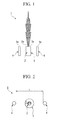
- a burner 1 used in the present embodiment is composed basically of a fuel nozzle 2 that jets a fuel stream (fuel fluid), a primary oxidant nozzle 3 that jets a primary oxidant stream (primary oxidant fluid), and a plurality of secondary oxidant nozzles 4 that jet a secondary oxidant stream (secondary oxidant fluid).
- the fuel nozzle 2, the primary oxidant nozzle 3 and the secondary oxidant nozzles 4 are all formed with cylindrical shapes, and are formed with the lengthwise directions of the nozzles all lying along the same direction. Accordingly, the direction in which the fuel nozzle 2 jets the fuel stream, the direction in which the primary oxidant nozzle 3 jets the primary oxidant stream, and the direction in which the secondary oxidant nozzles 4 jet the secondary oxidant streams are all the same direction.
- the direction in which the secondary oxidant nozzles 4 jet the secondary oxidant streams is not limited to the configuration described above, and the direction of the secondary oxidant streams need not necessarily be the same as the other streams.
- the secondary oxidant nozzles 4 may be installed with an outward-facing angle of up to 20° relative to the lengthwise direction of the primary oxidant nozzle 3.
- a jetting surface 2a provided at the jetting outlet of the fuel nozzle 2, a jetting surface 3a provided at the jetting outlet of the primary oxidant nozzle 3, and jetting surfaces 4a provided at the jetting outlets of the secondary oxidant nozzles 4 are all formed within the same plane. Accordingly, as illustrated in FIG. 1 , when the burner 1 is viewed from the side, the jetting surface 2a of the fuel nozzle 2, the jetting surface 3a of the primary oxidant nozzle 3, and the jetting surfaces 4a of the secondary oxidant nozzles 4 exist along a single straight line.
- the primary oxidant nozzle 3 is provided around the periphery of the fuel nozzle 2 or near the fuel nozzle 2.
- the expression that the primary oxidant nozzle 3 is provided "around the periphery or near" the fuel nozzle 2 means that the primary oxidant nozzle 3 and the fuel nozzle 2 are positioned within a specified distance of each other, and means that the primary oxidant nozzle 3 is positioned substantially adjacent to the fuel nozzle 2.
- the oxidant stream can be jetted from a position that is substantially adjacent to the position from which the fuel stream is jetted.
- the fuel nozzle 2 and the primary oxidant nozzle 3 are formed concentrically.
- the fuel nozzle 2 is formed with a circular cylindrical shape
- the primary oxidant nozzle 3 is formed so as to encircle the outer periphery of the fuel nozzle 2.
- the primary oxidant nozzle 3 is formed so that the cross-sectional shape of the nozzle is a ring shape (donut shape) having a specific width h, and the fuel nozzle 2 is positioned inside the inner periphery of the ring-shaped primary oxidant nozzle 3.
- the positioning of the fuel nozzle 2 and the primary oxidant nozzle 3 is not limited to the configuration described above, and the cross-sectional shape of the primary oxidant nozzle 3 need not necessarily be a ring shape, provided that the primary oxidant nozzle 3 is provided substantially around the periphery of the fuel nozzle 2 or near the fuel nozzle 2.
- a plurality of the secondary oxidant nozzles 4 are disposed in symmetrical positions centered around the fuel nozzle 2. Accordingly, when viewed in plan view, as illustrated in FIG. 2 , the secondary oxidant nozzles 4 are disposed in point symmetrical positions relative to the fuel nozzle 2.
- the distance 1 between the secondary oxidant nozzles 4 is preferably within a range from 10 to 50 cm, and more preferably from 30 to 50 cm. Further, the range for the distance I at a desired calorific value may be set using the 1/3 power law of the desired calorific value relative to 100 Mcal which is a base value of the fuel calorific value.
- the positioning of the plurality of secondary oxidant nozzles 4 is not limited to the configuration described above, and the secondary oxidant nozzles 4 may be positioned within a desired distance range from the fuel nozzle 2 determined in accordance with factors such as the flow velocities of the fuel stream, the primary oxidant stream and the secondary oxidant streams.
- FIG. 1 and FIG. 2 illustrate an example in which two of the secondary oxidant nozzles 4 are provided, but the present invention is not limited to this configuration, and three or more secondary oxidant nozzles 4 may also be used.
- the fuel nozzle 2 is preferably positioned at a position equivalent to the center of the shape formed having each of the secondary oxidant nozzles 4 at an apex. The following description focuses on the case in which two secondary oxidant nozzles 4 are provided.
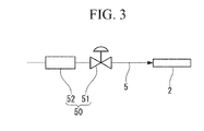
- a fuel supply line 5 that supplies the fuel stream is connected to the fuel nozzle 2.
- Natural gas (LNG) is a typical example of the fuel stream, but a liquid fuel such as a heavy oil may also be used.
- a forced oscillation device 50 for causing a periodic change in the flow rate of the fuel stream is provided within the fuel supply line 5.
- this forced oscillation device 50 describes a control unit containing a flow rate control valve 51 provided within the fuel supply line 5, and a flow rate meter 52 that controls the flow rate control valve 51.
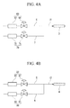
- a primary oxidant supply line 11 that supplies the primary oxidant stream is connected to the primary oxidant nozzle 3.
- the primary oxidant supply line 11 branches upstream into a primary air supply line 6 that supplies air and a primary oxygen supply line 7 that supplies oxygen.
- the primary oxidant stream is a mixed gas of air and oxygen, but nitrogen gas, carbon dioxide gas or a combustion exhaust gas or the like may also be used instead of air.
- Substantially pure oxygen such as industrial pure oxygen is preferably used as the oxygen.
- Forced oscillation devices 60 and 70 for causing periodic change in the flow rate of the air and the flow rate of the oxygen respectively are provided within the primary air supply line 6 and the primary oxygen supply line 7 respectively.
- these forced oscillation devices 60 and 70 describe control units each containing a flow rate control valve 61 or 71 provided within the primary air supply line 6 or the primary oxygen supply line 7, and a flow rate meter 62 or 72 that controls the flow rate control valve 61 or 71.
- the secondary oxidant nozzles 4 are controlled in the same manner as the primary oxidant nozzle 3.
- a secondary oxidant supply line 12 that supplies the secondary oxidant stream is connected to each of the secondary oxidant nozzles 4.
- the secondary oxidant supply line 12 branches upstream into a secondary air supply line 8 that supplies air and a secondary oxygen supply line 9 that supplies oxygen.
- the secondary oxidant stream is a mixed gas of air and oxygen, but nitrogen gas, carbon dioxide gas or a combustion exhaust gas or the like may also be used instead of air.
- Substantially pure oxygen such as industrial pure oxygen is preferably used as the oxygen.
- Forced oscillation devices 80 and 90 for causing periodic change in the flow rate of the air and the flow rate of the oxygen respectively are provided within the secondary air supply line 8 and the secondary oxygen supply line 9 respectively.
- these forced oscillation devices 80 and 90 describe control units each containing a flow rate control valve 81 or 91 provided within the secondary air supply line 8 or the secondary oxygen supply line 9, and a flow rate meter 82 or 92 that controls the flow rate control valve 81 or 91.
- the secondary oxidant supply line 12 is formed so as to branch into two downstream, enabling the secondary oxidant stream to be supplied to both of the secondary oxidant nozzles 4. Accordingly, when the flow rate and the oxygen concentration of the secondary oxidant stream supplied to each of the secondary oxidant nozzles 4 is changed periodically, the changes occur with the same frequency for both secondary oxidant nozzles 4.
- the fuel stream and oxidant streams are supplied via the above lines 5, 11 and 12 to each of the nozzles 2, 3 and 4.
- the flow rate of the fluid jetted from each of the nozzles 2, 3 and 4 can be controlled.
- First is a description of the relationship between the flow rate of an oxidant stream and the oxygen concentration of the oxidant stream, using the primary oxidant stream as an example.
- the secondary oxidant streams also adopt the same relationship.
- the flow rates of the air and pure oxygen that constitute the primary oxidant stream can be changed using the forced oscillation device 60 and the forced oscillation device 70 respectively.
- the oxygen concentration will be constant.
- the flow rate of the primary oxidant stream is kept constant, while the flow rate of pure oxygen and the flow rate of air are changed periodically with the same waveform and the same fluctuation range but with a phase difference of ⁇ , as illustrated in FIG. 6 , then the oxygen concentration can be changed periodically.
- the oxygen concentration within the primary oxidant stream can be changed within a range from approximately 21% to 100%.
- the oxygen concentration of the primary oxidant stream when the flow rate of pure oxygen is zero, the oxygen concentration of the primary oxidant stream will be equal to the oxygen concentration of air, meaning the oxygen concentration is approximately 21 %. In contrast, when the flow rate of air is zero, the primary oxidant stream will be composed solely of pure oxygen, meaning the oxygen concentration is 100%.
- the flow rate of the primary oxidant stream when the flow rate of the primary oxidant stream is changed periodically, then as illustrated in FIG. 7 , the flow rate of pure oxygen can be changed periodically, while the air is provided at a constant flow rate.
- the flow rate of pure oxygen reaches a maximum
- the oxygen concentration reaches a maximum
- the flow rate of pure oxygen is at a minimum
- the oxygen concentration is also at a minimum.
- the oxygen concentration can be changed periodically within a range from approximately 21 % to approximately 61%.
- the ratio between the flow rates of pure oxygen and air is 1 to 1, and the oxygen concentration within the primary oxidant stream is approximately 61%.
- the primary oxidant stream will be composed solely of air, meaning the oxygen concentration is approximately 21%.
- the above description presents a method in which the flow rate of air is held constant while the flow rate of pure oxygen is changed periodically, but the flow rate of pure oxygen may be held constant while the flow rate of air is changed periodically, or both flow rates may be changed periodically.
- the flow rate of the oxidant stream and the oxygen concentration are controlled.
- the oxygen ratio describes the value obtained by dividing the supplied amount of oxygen, supplied as the oxidant stream to the burner 3 and the burner 4, by the theoretically required amount of oxygen necessary for combusting the fuel fluid supplied to the burner 2. Accordingly, theoretically, the state in which the oxygen ratio is 1.0 describes the state in which complete combustion can be achieved without any excess or deficiency of oxygen.
- the theoretically required amount of oxygen for combustion of LNG, although dependent on the LNG composition, is typically a molar ratio of approximately 2.3 times the amount of LNG.
- the flow rate of the fuel stream is kept constant, while the flow rate of at least one of the primary oxidant stream and the secondary oxidant streams is changed periodically. Further, the flow rates are controlled so that the oxygen concentration within the oxidant stream composed of the primary oxidant stream and the secondary oxidant streams is changed periodically, and a periodic change is also imparted to the oxygen ratio. Control is performed so that a difference is provided between the periodic change in the oxygen concentration and the periodic change in the oxygen ratio. In particular, control is preferably performed so that a state having a low oxygen ratio and a high oxygen concentration, and a state having a high oxygen ratio and a low oxygen concentration exist periodically.
- the expression that a difference is provided between the periodic changes refers to any state other than the state in which the waveforms, frequencies and phases completely coincide. For example, even if the waveforms of the oxygen ratio and the oxygen concentration are both sine waves, and both waveforms have the same frequency, if a phase difference exists between the waveforms, then this is deemed to be a provided difference in the periodic changes.
- the flow rate of the air and the flow rate of pure oxygen supplied to the primary oxidant stream are both kept constant, the flow rate of pure oxygen supplied to the secondary oxidant streams is kept constant, and the flow rate of the air supplied to the secondary oxidant streams is changed periodically.
- the flow rate of the primary oxidant stream is constant, the flow rate of the secondary oxidant streams changes periodically.
- the flow rates of the air and pure oxygen supplied to the primary oxidant stream and the pure oxygen supplied to the secondary oxidant streams are all constant, because the flow rate of the air supplied to the secondary oxidant streams changes periodically, the oxygen concentration also changes periodically. Specifically, when the flow rate of the air supplied to the secondary oxidant streams reaches a maximum, the oxygen concentration falls to a minimum, whereas when the flow rate of the air supplied to the secondary oxidant streams is at a minimum, the oxygen concentration reaches a maximum.
- the theoretically required amount of oxygen remains constant. Looking at the combined oxidant stream, the absolute amount of supplied oxygen will reach a maximum when the flow rate of air supplied to the secondary oxidant streams is at a maximum, whereas the amount of oxygen will be at a minimum when the flow rate of air supplied to the secondary oxidant streams is at a minimum. Accordingly, the oxygen ratio calculated by dividing the supplied amount of oxygen by the theoretically required amount of oxygen reaches a maximum when the flow rate of air supplied to the secondary oxidant streams is at a maximum, whereas the oxygen ratio is at a minimum when the flow rate of air supplied to the secondary oxidant streams is at a minimum.
- the oxygen ratio reaches a maximum when the oxygen concentration is at a minimum, whereas the oxygen ratio is at a minimum when the oxygen concentration reaches a maximum, meaning a difference exists in the periodic changes of the oxygen concentration and the oxygen ratio.
- the above control method is merely one example, and the present invention is not limited to this type of control.
- the flow rates of the air and pure oxygen supplied to the primary oxidant stream and the air and pure oxygen supplied to the secondary oxidant streams may be controlled appropriately within the desired ranges.
- Periodically changing the flow rate of the secondary oxidant streams is particularly preferred, and the frequency of the periodic change is preferably at least 0.01 Hz but not more than 20 Hz, and more preferably at least 0.02 Hz but not more than 2 Hz.
- the flow rate of the primary oxidant stream relative to the flow rate of the overall oxidant stream, on a time-averaged basis is preferably at least 10% but not more than 70%, and more preferably at least 10% but not more than 50%.
- the flow rate of the secondary oxidant stream relative to the flow rate of the overall oxidant stream, on a time-averaged basis is preferably at least 30% but not more than 90%, and more preferably at least 50% but not more than 90%.
- the oxygen concentration within the oxidant stream is preferably at least 5% but not more than 100%, and more preferably at least 21% but not more than 100%. In terms of the oxygen ratio, this is controlled so as to change periodically, but the difference between the upper limit and the lower limit of the oxygen ratio (namely, the amplitude of the oxygen ratio) is preferably at least 0.2. Furthermore, the time-averaged value of the oxygen ratio is preferably at least 1.0, and more preferably 1.05 or greater.
- the periodic changes in the oxygen ratio and the oxygen concentration preferably occur with the same frequency, and the phase difference between the changes is preferably at least ⁇ /2 but not more than 3 ⁇ /2 (namely, the absolute value of the phase difference between the oxygen ratio and the oxygen concentration is at least ⁇ /2).
- the phase difference is most preferably ⁇ .
- the oxidant stream is composed of a primary oxidant stream jetted from around the periphery of the fuel stream or from a position near the fuel stream, and a plurality of secondary oxidant streams, the way in which the oxidant stream is supplied differs from that when combustion is performed in a conventional manner using a single oxidant stream.
- the oxygen concentration and the oxygen ratio are changed periodically, and a difference is provided between these periodic changes, NOx can be reduced significantly and reliably.
- combustion using a burner assumes the use of a heat utilization facility or apparatus such as a melting furnace or a heating furnace, and of course, from the viewpoint of energy conservation, improving the heat utilization efficiency is of critical importance. Limiting the discharge of carbon dioxide gas is also required.
- the burner combustion method of the present embodiment is also able to satisfy these demands.
- the burner combustion method of the present embodiment can not only be applied when designing new combustors, but can also be applied to the burners of existing combustors.
- Comparison of the present embodiment with the first embodiment reveals that this embodiment differs in that control is performed so that the flow rate of the fuel stream changes periodically.
- the remaining configuration of the burner is the same as the first embodiment.
- the flow rate of the fuel stream is changed periodically in this embodiment, and the periodic change in the flow rate of the fuel stream and the periodic change in the oxygen ratio are controlled so as to occur at the same frequency.
- the phase difference between the periodic changes in the flow rate of the fuel stream and the oxygen ratio is preferably controlled so as to be at least ⁇ /2 but not more than 3 ⁇ /2 (namely, the absolute value of the phase difference between the periodic changes in the flow rate of the fuel stream and the oxygen ratio is at least ⁇ /2).
- the phase difference is most preferably ⁇ .
- the flow rate of the primary air and the flow rate of the primary oxygen supplied to the primary oxidant stream are both kept constant, the flow rate of pure oxygen supplied to the secondary oxidant streams is kept constant, the flow rate of the air supplied to the secondary oxidant streams is changed periodically, and the flow rate of the fuel stream is controlled so as to achieve a phase difference of ⁇ relative to this periodic change in the flow rate of the air supplied to the secondary oxidant streams.
- the flow rate of the primary oxidant stream remains constant, but the flow rate of the secondary oxidant streams is changed periodically. Further, because the flow rate of the secondary oxidant streams changes periodically, the oxygen concentration also changes periodically, and when the flow rate of air supplied to the secondary oxidant streams reaches a maximum, the oxygen concentration is at a minimum, whereas when the flow rate of air supplied to the secondary oxidant streams is at a minimum, the oxygen concentration reaches a maximum.
- the flow rate of air supplied to the secondary oxidant streams when the flow rate of air supplied to the secondary oxidant streams is at a maximum, the amount of oxygen reaches a maximum, and when the flow rate of air supplied to the secondary oxidant streams is at a minimum, the amount of oxygen is also at a minimum.
- the flow rate of air supplied to the secondary oxidant streams when the flow rate of air supplied to the secondary oxidant streams is at a maximum, the flow rate of the fuel stream is at a minimum, and the theoretically required amount of oxygen also falls to its smallest value.
- the flow rate of air supplied to the secondary oxidant streams when the flow rate of air supplied to the secondary oxidant streams is at a minimum, the flow rate of the fuel stream reaches a maximum, and the theoretically required amount of oxygen also reaches a maximum.
- the oxygen ratio calculated by dividing the supplied amount of oxygen by the theoretically required amount of oxygen reaches a maximum when the flow rate of air supplied to the secondary oxidant streams is at a maximum, whereas the oxygen ratio is at a minimum when the flow rate of air supplied to the secondary oxidant streams is at a minimum.
- the periodic changes in the oxygen concentration, the oxygen ratio and the flow rate of the fuel stream are controlled so that the oxygen ratio reaches a maximum and the flow rate of the fuel stream is at a minimum when the oxygen concentration is at a minimum, whereas the oxygen ratio is at a minimum and the flow rate of the fuel stream is at a minimum when the oxygen concentration reaches a maximum.
- the above control method is merely one example, and the present invention is not limited to this type of control.
- the flow rates of the fuel stream, the air and pure oxygen supplied to the primary oxidant stream, and the air and pure oxygen supplied to the secondary oxidant streams may be controlled appropriately within the desired ranges.
- the way in which the oxidant stream is supplied differs from that when combustion is performed in a conventional manner using a single oxidant stream, and as a result, NOx can be reduced significantly and reliably.
- Example 1 tests were performed using a burner 1 in which, as illustrated in FIG. 1 and FIG. 2 , a primary oxidant nozzle 3 was positioned in the side surface of a rectangular test furnace so as to encircle the outer periphery of a fuel nozzle 2, and two secondary oxidant nozzles 4 were positioned in the same plane in bilaterally symmetrical positions centered across the fuel nozzle 2.
- the distance 1 between the two secondary oxidant nozzles 4 was 50 cm, and the flow velocity of the secondary oxidant streams jetted from the secondary oxidant nozzles 4 was 100 m/s.
- a plurality of water-cooled tubes were disposed in a direction orthogonal to the jetting direction of the nozzles, and a resistance temperature detector was inserted into the inlet and outlet of each water-cooled tube.
- LNG was used as the fuel, the flow rate of the fuel stream was kept constant, the time-averaged oxygen ratio was set to 1.05, and the time-averaged oxygen concentration within the oxidant stream (the combination of the primary oxidant stream and the secondary oxidant streams) was set to a value of 40%, which is an amount at which a reduction in the amount of exhaust gas can generally be expected.
- the flow rate of oxygen contained within the primary oxidant stream and the flow rate of oxygen contained within the secondary oxidant streams namely, relative to the total amount of oxygen supplied to the burner 1
- the flow rate of oxygen contained within the primary oxidant stream was set to 30%, and the flow rate of oxygen contained within the secondary oxidant streams was set to 70%.
- oxygen equivalent to 31.5% of the theoretically required amount of oxygen was supplied from the primary oxidant stream, and on a time-averaged basis, 73.5% of the theoretically required amount of oxygen was supplied from the secondary oxidant streams.
- the flow rate of the primary oxidant stream was kept constant, and the flow rates of oxygen and air within the secondary oxidant streams were changed periodically.
- a test was performed with the oxygen concentration changed within a range from at least 21% to not more than 100%, and the oxygen ratio changed within a range from at least 0.6 to not more than 1.5, with the frequency of the changes varied within a range from 0.017 Hz to 100 Hz, and the NOx emission rate, the CO concentration and the heat transfer efficiency were measured.
- the results for the NOx emission rate are illustrated in FIG. 8
- the results for the CO concentration are illustrated in FIG. 9
- the results for the heat transfer efficiency are illustrated in FIG. 10 .
- the NOx emission rate was measured by suctioning the exhaust gas continuously from the flue using a suction pump, and then using a chemiluminescence-based continuous NOx concentration measurement apparatus to measure the NOx concentration.
- the CO concentration was measured by suctioning the exhaust gas continuously from the flue using a suction pump, and then using an infrared absorption-based continuous CO concentration measurement apparatus to measure the CO concentration.
- the heat transfer efficiency was determined by calculating the amount of heat transfer from the temperature change and the flow rate of the water flowing through the water-cooled tubes positioned in the bottom of the test furnace.
- the NOx emission rate, the CO concentration and the heat transfer efficiency were also measured for an example of the conventional technology, in which a burner having a structure in which an oxidant nozzle was positioned around the periphery of the fuel nozzle was used, and normal combustion was performed with the oxygen concentration fixed at 40%.
- NOx(ref) NOx(ref)
- CO(ref) CO(ref)
- the horizontal axes represent the frequency
- the vertical axes represent the NOx emission rate normalized using the reference value NOx(ref) (NOx/NOx(ref)), the CO concentration normalized using the reference value CO(ref) (CO/CO(ref)), and the heat transfer efficiency normalized using the reference heat transfer efficiency(ref) (heat transfer efficiency/ heat transfer efficiency(ref)) respectively.
- the NOx emission rate was able to be significantly reduced. Further, it was also evident that the NOx emission rate tended to increase rapidly when the frequency of the change in the flow rate of the secondary oxidant streams reached 20 Hz, and therefore the frequency is preferably set to 20 Hz or less. Further, as is evident from FIG. 9 , regardless of whether or not the secondary oxidant streams were used, and regardless of the frequency of the periodic change in the flow rate of the secondary oxidant streams, there tended to be little effect on the CO concentration. Furthermore, as is evident from FIG. 10 , by periodically changing the flow rate of the secondary oxidant streams, the heat transfer efficiency was able to be increased. Further, the heat transfer efficiency tended to be largely unaffected by the frequency of the secondary oxidant streams.
- Example 2 the distance 1 between the two secondary oxidant nozzles 4 was changed, and the effect on the NOx emission rate was investigated. Specifically, the frequency of the secondary oxidant streams was varied within a range from 0.017 Hz to 100 Hz under 5 different conditions in which the distance 1 between the two secondary oxidant nozzles 4 was set to 10, 20, 30, 40 or 50 cm. The remaining conditions were the same as those used for Example 1.
- FIG. 11 The results of measuring the NOx emission rate are shown in FIG. 11 .
- the horizontal axis represents the frequency
- the vertical axis represents the NOx emission rate normalized using the reference value NOx(ref) from Example 1.
- Example 3 the flow velocity of the secondary oxidant streams was changed by altering the nozzle diameter, and the effect on the NOx emission rate was investigated. Specifically, the frequency of the secondary oxidant streams was varied within a range from 0.017 Hz to 100 Hz under 7 different conditions in which the flow velocity of the secondary oxidant streams was set to 10 m/s, 20 m/s, 30 m/s, 60 m/s, 100 m/s, 200 m/s or 300 m/s. The remaining conditions were the same as those used for Example 1.
- FIG. 12 The results of measuring the NOx emission rate are shown in FIG. 12 .
- the horizontal axis represents the frequency
- the vertical axis represents the NOx emission rate normalized using the reference value NOx(ref) from Example 1.
- the NOx emission rate tended to decrease.
- a flow velocity of at least 20 m/s was preferable, and a flow rate of 60 m/s or greater was more preferable.
- the flow velocity of the secondary oxidant streams was found to have no significant effect on the CO concentration.
- the heat transfer efficiency was also measured in Example 3, but the flow velocity of the secondary oxidant streams tended to have no significant effect on the heat transfer efficiency.
- a burner combustion method that exhibits an NOx reduction effect and has practical value can be provided.
- the present invention relates to this burner combustion method, and can therefore be widely used in manufacturing processes that use a combustor.
Landscapes
- Engineering & Computer Science (AREA)
- Chemical & Material Sciences (AREA)
- Combustion & Propulsion (AREA)
- Mechanical Engineering (AREA)
- General Engineering & Computer Science (AREA)
- Air Supply (AREA)
- Fluidized-Bed Combustion And Resonant Combustion (AREA)
Abstract
Description
- The present invention relates to a burner combustion method.
Priority is claimed on Japanese Patent Application No.2011-014080, filed January 26, 2011 - In recent years, as considerable attention has been focused on environmental issues facing the earth, the reduction of nitrogen oxides (NOx) has been identified as one important issue, and is an issue requiring urgent attention. Among methods of reducing NOx, technology for inhibiting generation of NOx is very important, and techniques such as exhaust gas recirculation, lean bum combustion, thick and thin fuel combustion, and staged combustion are already known, and are being widely employed in industrial applications through to consumer applications. Although NOx countermeasures have progressed to some degree through application of low NOx combustors that apply these techniques, more effective methods of further reducing NOx are still being sought.
- Among methods that aim to address the issues described above, one example of a method of reducing NOx that is the subject of ongoing research and development is a method of performing a type of timed thick and thin fuel combustion in which the flow rates of the fuel and the oxidant are changed periodically (hereafter referred to as "forced oscillating combustion") (see
Patent Documents 1 to 6). - In this method, by oscillating control of the supply flow rate of either the fuel or the oxidant, or both the fuel and the oxidant, the stoichiometric ratio of the combustion flame is altered to generate alternating fuel-rich combustion and fuel-lean combustion, thereby achieving a reduction in the emission of NOx.
- Further,
Patent Document 7 discloses a method of reducing NOx that utilizes a pulsed combustion in which the oxidant is enriched using pure oxygen, so-called "forced oscillating combustion", as well as an apparatus for implementing this method. - Furthermore,
Patent Documents 8 to 14 disclose so-called staged combustion methods in which the fuel and/or the oxidant are jetted into the furnace or combustion chamber in multiple stages, and also mention many effects of low NOx methods. -
- Patent Document 1: European Patent Publication, No.
0046898 - Patent Document 2:
U.S. Patent Publication, No. 4,846,665 - Patent Document 3: Japanese Unexamined Patent Application, First Publication No.
Hei 6-213411 - Patent Document 4: Japanese Unexamined Patent Application, First Publication No.
2000-171005 - Patent Document 5: Japanese Unexamined Patent Application, First Publication No.
2000-1710032 - Patent Document 6: Japanese Unexamined Patent Application, First Publication No.
2001-311505 - Patent Document 7: Japanese Unexamined Patent Application, First Publication No.
Hei 5-215311 - Patent Document 8: Japanese Unexamined Patent Application, First Publication No.
Hei 6-257723 - Patent Document 9: Japanese Unexamined Patent Application, First Publication No.
Hei 7-233920 - Patent Document 10: Japanese Patent (Granted) Publication No.
4,132,409 - Patent Document 11: Japanese Unexamined Patent Application, First Publication No.
2007-232364 - Patent Document 12: Japanese Unexamined Patent Application, First Publication No.
Hei 6-213410 - Patent Document 13: Published Japanese Translation No.
2004-523721 of PCT - Patent Document 14:
U.S. Patent Publication No. 5,601,425 - However, when the inventors of the present invention undertook further testing of the reduction effects, although they were able to identify some NOx reduction effects, they were unable to obtain reduction effects significant enough to have practical value, confirming that the development of innovative new technology is still required.
Against this type of background, a method of reducing NOx that is of practical value is keenly sought, but no such appropriately effective method currently exists. - In order to address the issues described above, the inventors of the present invention undertook intensive research aimed at developing a method of reducing NOx that is of practical value. As a result, they discovered that by supplying a plurality of oxidant streams to the burner, and periodically changing at least one of a primary oxidant stream that is jetted from around the periphery of the fuel, and secondary oxidant streams that are jetted from positions separated from the fuel by a specified distance, an NOx reduction effect significantly larger than conventional effects could be obtained.
- In other words, the present invention provides the aspects described below. (1) A burner combustion method for supplying and combusting an oxidant stream and a fuel stream, wherein the oxidant stream is composed of a primary oxidant stream jetted from around the periphery of the fuel stream or from a position near the fuel stream, and a plurality of secondary oxidant streams, and by periodically changing the flow rate of at least one of the primary oxidant stream and the plurality of secondary oxidant streams, and also causing a periodic change in the oxygen concentration within the oxidant stream, causing a periodic change in the oxygen ratio which is calculated by dividing the supplied amount of oxygen, supplied by the oxidant stream, by the theoretically required amount of oxygen, and providing a difference between the periodic changes in the oxygen concentration and the oxygen ratio, the combustion state adopts a periodic oscillating state.
- (2) The burner combustion method according to (1) above, wherein the plurality of secondary oxidant streams are jetted from symmetrical positions centered around the fuel stream.
- (3) The burner combustion method according to (1) of (2) above, wherein the ratio of the flow rate of the primary oxidant stream relative to the flow rate of the oxidant stream is at least 10% but not more than 70%.
- (4) The burner combustion method according to any one of (1) to (3) above, wherein the flow rate of the secondary oxidant streams is changed periodically.
- (5) The burner combustion method according to (4) above, wherein the frequency of the periodic change in the flow rate of the secondary oxidant streams is at least 0.01 Hz but not more than 20 Hz.
- (6) The burner combustion method according to any one of (1) to (5) above, wherein the difference between the upper limit and the lower limit of the periodically changing oxygen ratio is at least 0.2, and the average value of the oxygen ratio across a single period is at least 1.0.
- (7) The burner combustion method according to any one of (1) to (6) above, wherein the periodic changes in the oxygen concentration and the oxygen ratio have the same frequency.
- (8) The burner combustion method according to (7) above, wherein the phase difference between the periodic changes in the oxygen concentration and the oxygen ratio is at least π/2 but not more than 3π/2.
- (9) The burner combustion method according to any one of (1) to (8) above, wherein the flow rate of the fuel stream is changed periodically, the periodic change in the flow rate of the fuel stream and the periodic change in the oxygen ratio have the same frequency, and the phase difference between the periodic changes in the flow rate of the fuel stream and the oxygen ratio is at least π/2 but not more than 3π/2.
- (10) The burner combustion method according to any one of (1) to (9) above, wherein the oxidant stream is composed of oxygen and air.
- (11) The burner combustion method according to any one of (1) to (9) above, wherein the oxidant stream is composed of oxygen and a combustion exhaust gas.
- (12) The burner combustion method according to (10) or (11) above, wherein the oxygen is substantially pure oxygen.
- The present invention can provide a burner combustion method that can significantly and reliably reduce NOx. Further, the present invention can not only be applied when designing new combustors, but can also be applied to existing combustors.
-
-
FIG. 1 is a side view illustrating an outline of a burner according to a first embodiment of the present invention. -
FIG. 2 is a plan view illustrating an outline of the burner according to the first embodiment of the present invention. -
FIG. 3 is a schematic view illustrating one example of a fuel nozzle used in the first embodiment of the present invention. -
FIG. 4A is a schematic view illustrating one example of a primary oxidant nozzle used in the first embodiment of the present invention. -
FIG. 4B is a schematic view illustrating one example of a secondary oxidant nozzle used in the first embodiment of the present invention -
FIG. 5 is a schematic view illustrating one example of lines of the burner according to the first embodiment of the present invention. -
FIG. 6 is a diagram illustrating one example of periodic changes in the oxygen flow rate and the air flow rate in the first embodiment of the present invention. -
FIG. 7 is a diagram illustrating another example of periodic changes in the oxygen flow rate and the air flow rate in the first embodiment of the present invention. -
FIG. 8 is a graph illustrating the relationship between the frequency and the NOx concentration in one example of the present invention. -
FIG. 9 is a graph illustrating the relationship between the frequency and the CO concentration in one example of the present invention. -
FIG. 10 is a graph illustrating the relationship between the frequency and the heat transfer efficiency in one example of the present invention. -
FIG. 11 is a graph illustrating the relationship between the frequency and the NOx concentration in one example of the present invention. -
FIG. 12 is a graph illustrating the relationship between the frequency and the NOx concentration in one example of the present invention. - Preferred examples of the present invention are described below, but the present invention is in no way limited by these examples. Additions, omissions, substitutions, and other modifications can be made without departing from the spirit or scope of the present invention.
- A burner combustion method that represents a first embodiment of application of the present invention is described below in detail with reference to the drawings. The drawings used in the following description have in some cases been drawn with certain features enlarged in order to assist with comprehension of those features, and as a result, the dimensional ratios between each of the structural elements in the drawings may not necessarily be the same as the actual ratios.
- As illustrated in
FIG. 1 and FIG. 2 , aburner 1 used in the present embodiment is composed basically of afuel nozzle 2 that jets a fuel stream (fuel fluid), aprimary oxidant nozzle 3 that jets a primary oxidant stream (primary oxidant fluid), and a plurality ofsecondary oxidant nozzles 4 that jet a secondary oxidant stream (secondary oxidant fluid). - As illustrated in
FIG. 1 , thefuel nozzle 2, theprimary oxidant nozzle 3 and thesecondary oxidant nozzles 4 are all formed with cylindrical shapes, and are formed with the lengthwise directions of the nozzles all lying along the same direction. Accordingly, the direction in which thefuel nozzle 2 jets the fuel stream, the direction in which theprimary oxidant nozzle 3 jets the primary oxidant stream, and the direction in which thesecondary oxidant nozzles 4 jet the secondary oxidant streams are all the same direction. However, the direction in which thesecondary oxidant nozzles 4 jet the secondary oxidant streams is not limited to the configuration described above, and the direction of the secondary oxidant streams need not necessarily be the same as the other streams. Thesecondary oxidant nozzles 4 may be installed with an outward-facing angle of up to 20° relative to the lengthwise direction of theprimary oxidant nozzle 3. - Further, a jetting
surface 2a provided at the jetting outlet of thefuel nozzle 2, a jettingsurface 3a provided at the jetting outlet of theprimary oxidant nozzle 3, and jettingsurfaces 4a provided at the jetting outlets of thesecondary oxidant nozzles 4 are all formed within the same plane. Accordingly, as illustrated inFIG. 1 , when theburner 1 is viewed from the side, the jettingsurface 2a of thefuel nozzle 2, the jettingsurface 3a of theprimary oxidant nozzle 3, and the jetting surfaces 4a of thesecondary oxidant nozzles 4 exist along a single straight line. - Further, the
primary oxidant nozzle 3 is provided around the periphery of thefuel nozzle 2 or near thefuel nozzle 2. Here, the expression that theprimary oxidant nozzle 3 is provided "around the periphery or near" thefuel nozzle 2 means that theprimary oxidant nozzle 3 and thefuel nozzle 2 are positioned within a specified distance of each other, and means that theprimary oxidant nozzle 3 is positioned substantially adjacent to thefuel nozzle 2.
As a result, the oxidant stream can be jetted from a position that is substantially adjacent to the position from which the fuel stream is jetted. - Furthermore, in the present embodiment, as illustrated in
FIG. 2 , thefuel nozzle 2 and theprimary oxidant nozzle 3 are formed concentrically. Specifically, thefuel nozzle 2 is formed with a circular cylindrical shape, and theprimary oxidant nozzle 3 is formed so as to encircle the outer periphery of thefuel nozzle 2. In other words, theprimary oxidant nozzle 3 is formed so that the cross-sectional shape of the nozzle is a ring shape (donut shape) having a specific width h, and thefuel nozzle 2 is positioned inside the inner periphery of the ring-shapedprimary oxidant nozzle 3. - However, the positioning of the
fuel nozzle 2 and theprimary oxidant nozzle 3 is not limited to the configuration described above, and the cross-sectional shape of theprimary oxidant nozzle 3 need not necessarily be a ring shape, provided that theprimary oxidant nozzle 3 is provided substantially around the periphery of thefuel nozzle 2 or near thefuel nozzle 2. - A plurality of the
secondary oxidant nozzles 4 are disposed in symmetrical positions centered around thefuel nozzle 2. Accordingly, when viewed in plan view, as illustrated inFIG. 2 , thesecondary oxidant nozzles 4 are disposed in point symmetrical positions relative to thefuel nozzle 2. When a fuel calorific value is based on a case of 100 Mcal, thedistance 1 between thesecondary oxidant nozzles 4 is preferably within a range from 10 to 50 cm, and more preferably from 30 to 50 cm. Further, the range for the distance I at a desired calorific value may be set using the 1/3 power law of the desired calorific value relative to 100 Mcal which is a base value of the fuel calorific value. - However, the positioning of the plurality of
secondary oxidant nozzles 4 is not limited to the configuration described above, and thesecondary oxidant nozzles 4 may be positioned within a desired distance range from thefuel nozzle 2 determined in accordance with factors such as the flow velocities of the fuel stream, the primary oxidant stream and the secondary oxidant streams. -
FIG. 1 and FIG. 2 illustrate an example in which two of thesecondary oxidant nozzles 4 are provided, but the present invention is not limited to this configuration, and three or moresecondary oxidant nozzles 4 may also be used. In the case of three or moresecondary oxidant nozzles 4, if the structure is viewed in plan view, then thefuel nozzle 2 is preferably positioned at a position equivalent to the center of the shape formed having each of thesecondary oxidant nozzles 4 at an apex. The following description focuses on the case in which twosecondary oxidant nozzles 4 are provided. - Next is a description of the lines used for supplying fluid to each of the nozzles.
As illustrated inFIG. 3 , afuel supply line 5 that supplies the fuel stream is connected to thefuel nozzle 2. Natural gas (LNG) is a typical example of the fuel stream, but a liquid fuel such as a heavy oil may also be used. - Furthermore, a forced
oscillation device 50 for causing a periodic change in the flow rate of the fuel stream is provided within thefuel supply line 5. Specifically, this forcedoscillation device 50 describes a control unit containing a flowrate control valve 51 provided within thefuel supply line 5, and aflow rate meter 52 that controls the flowrate control valve 51. - As illustrated in
FIG. 4A , a primaryoxidant supply line 11 that supplies the primary oxidant stream is connected to theprimary oxidant nozzle 3. The primaryoxidant supply line 11 branches upstream into a primaryair supply line 6 that supplies air and a primaryoxygen supply line 7 that supplies oxygen. The primary oxidant stream is a mixed gas of air and oxygen, but nitrogen gas, carbon dioxide gas or a combustion exhaust gas or the like may also be used instead of air. Substantially pure oxygen such as industrial pure oxygen is preferably used as the oxygen. -
Forced oscillation devices air supply line 6 and the primaryoxygen supply line 7 respectively. Specifically, these forcedoscillation devices rate control valve air supply line 6 or the primaryoxygen supply line 7, and aflow rate meter rate control valve - In those cases where an oxidant having a fixed oxygen concentration is used as the primary oxidant stream, then an oxidant that has been fixed at that particular concentration need simply be supplied, and therefore the primary
oxidant supply line 11 need not branch upstream, and a forced oscillation device (not shown in the drawing) may simply be provided within the primaryoxidant supply line 11. - The
secondary oxidant nozzles 4 are controlled in the same manner as theprimary oxidant nozzle 3. In other words, as illustrated inFIG. 4B , a secondaryoxidant supply line 12 that supplies the secondary oxidant stream is connected to each of thesecondary oxidant nozzles 4. The secondaryoxidant supply line 12 branches upstream into a secondaryair supply line 8 that supplies air and a secondaryoxygen supply line 9 that supplies oxygen. The secondary oxidant stream is a mixed gas of air and oxygen, but nitrogen gas, carbon dioxide gas or a combustion exhaust gas or the like may also be used instead of air. Substantially pure oxygen such as industrial pure oxygen is preferably used as the oxygen. -
Forced oscillation devices air supply line 8 and the secondaryoxygen supply line 9 respectively. Specifically, these forcedoscillation devices rate control valve air supply line 8 or the secondaryoxygen supply line 9, and aflow rate meter rate control valve - In those cases where an oxidant having a fixed oxygen concentration is used as the secondary oxidant stream, then an oxidant that has been fixed at that particular concentration need simply be supplied, and therefore the secondary
oxidant supply line 12 need not branch upstream, and a forced oscillation device (not shown in the drawing) may simply be provided within the primaryoxidant supply line 12. - Further, because two of the
secondary oxidant nozzles 4 are provided, as illustrated inFIG. 5 , the secondaryoxidant supply line 12 is formed so as to branch into two downstream, enabling the secondary oxidant stream to be supplied to both of thesecondary oxidant nozzles 4.
Accordingly, when the flow rate and the oxygen concentration of the secondary oxidant stream supplied to each of thesecondary oxidant nozzles 4 is changed periodically, the changes occur with the same frequency for bothsecondary oxidant nozzles 4. - The fuel stream and oxidant streams are supplied via the
above lines nozzles oscillation devices nozzles - Next is a description of control of the flow rate of the fluid supplied from each of the
nozzles
In the following description, for the sake of convenience, it is assumed that pure oxygen is supplied from the primaryoxygen supply line 7 and the secondaryoxygen supply line 9, air (having an oxygen concentration of approximately 21%) is supplied from the primaryair supply line 6 and the secondaryair supply line 8, and liquefied natural gas (LNG) is supplied from thefuel supply line 5. - First is a description of the relationship between the flow rate of an oxidant stream and the oxygen concentration of the oxidant stream, using the primary oxidant stream as an example. The secondary oxidant streams also adopt the same relationship.
The flow rates of the air and pure oxygen that constitute the primary oxidant stream can be changed using the forcedoscillation device 60 and the forcedoscillation device 70 respectively. - When the flow rate of the primary oxidant stream is constant, if the flow rates of the pure oxygen and air are both kept constant, then the oxygen concentration will be constant.
On the other hand, if the flow rate of the primary oxidant stream is kept constant, while the flow rate of pure oxygen and the flow rate of air are changed periodically with the same waveform and the same fluctuation range but with a phase difference of π, as illustrated inFIG. 6 , then the oxygen concentration can be changed periodically. By adopting this type of configuration, because the increases and decreases in the flow rates of pure oxygen and air cancel each other out, the flow rate of the primary oxidant stream itself can be controlled at a constant level. - In this case, if the flow rates are controlled so that the minimum values for the flow rates of pure oxygen and air both reach zero, then the oxygen concentration within the primary oxidant stream can be changed within a range from approximately 21% to 100%.
- In other words, when the flow rate of pure oxygen is zero, the oxygen concentration of the primary oxidant stream will be equal to the oxygen concentration of air, meaning the oxygen concentration is approximately 21 %. In contrast, when the flow rate of air is zero, the primary oxidant stream will be composed solely of pure oxygen, meaning the oxygen concentration is 100%.
- Further, when the flow rate of the primary oxidant stream is changed periodically, then as illustrated in
FIG. 7 , the flow rate of pure oxygen can be changed periodically, while the air is provided at a constant flow rate. In this case, when the flow rate of pure oxygen reaches a maximum, the oxygen concentration reaches a maximum, and when the flow rate of pure oxygen is at a minimum, the oxygen concentration is also at a minimum. - For example, if the flow rate of pure oxygen is controlled so that the maximum value is the same as the flow rate of air and the minimal value is zero, then the oxygen concentration can be changed periodically within a range from approximately 21 % to approximately 61%. In other words, when the flow rate of pure oxygen is at a maximum, the ratio between the flow rates of pure oxygen and air is 1 to 1, and the oxygen concentration within the primary oxidant stream is approximately 61%. Further, when the flow rate of pure oxygen is at a minimum, the primary oxidant stream will be composed solely of air, meaning the oxygen concentration is approximately 21%.
- As an example of a method of periodically changing the flow rate of the primary oxidant stream, the above description presents a method in which the flow rate of air is held constant while the flow rate of pure oxygen is changed periodically, but the flow rate of pure oxygen may be held constant while the flow rate of air is changed periodically, or both flow rates may be changed periodically.
In the manner described above, the flow rate of the oxidant stream and the oxygen concentration are controlled. - Next is a description of the oxygen ratio. The oxygen ratio describes the value obtained by dividing the supplied amount of oxygen, supplied as the oxidant stream to the
burner 3 and theburner 4, by the theoretically required amount of oxygen necessary for combusting the fuel fluid supplied to theburner 2. Accordingly, theoretically, the state in which the oxygen ratio is 1.0 describes the state in which complete combustion can be achieved without any excess or deficiency of oxygen. The theoretically required amount of oxygen for combustion of LNG, although dependent on the LNG composition, is typically a molar ratio of approximately 2.3 times the amount of LNG. - Next is a description of the control of the fuel stream, the primary oxidant stream and the secondary oxidant stream in the present embodiment.
In the present embodiment, the flow rate of the fuel stream is kept constant, while the flow rate of at least one of the primary oxidant stream and the secondary oxidant streams is changed periodically. Further, the flow rates are controlled so that the oxygen concentration within the oxidant stream composed of the primary oxidant stream and the secondary oxidant streams is changed periodically, and a periodic change is also imparted to the oxygen ratio.
Control is performed so that a difference is provided between the periodic change in the oxygen concentration and the periodic change in the oxygen ratio. In particular, control is preferably performed so that a state having a low oxygen ratio and a high oxygen concentration, and a state having a high oxygen ratio and a low oxygen concentration exist periodically. - Here, the expression that a difference is provided between the periodic changes refers to any state other than the state in which the waveforms, frequencies and phases completely coincide. For example, even if the waveforms of the oxygen ratio and the oxygen concentration are both sine waves, and both waveforms have the same frequency, if a phase difference exists between the waveforms, then this is deemed to be a provided difference in the periodic changes.
- In one example of the type of control described above, the flow rate of the air and the flow rate of pure oxygen supplied to the primary oxidant stream are both kept constant, the flow rate of pure oxygen supplied to the secondary oxidant streams is kept constant, and the flow rate of the air supplied to the secondary oxidant streams is changed periodically.
- In this case, although the flow rate of the primary oxidant stream is constant, the flow rate of the secondary oxidant streams changes periodically.
Further, looking at the combined oxidant stream, although the flow rates of the air and pure oxygen supplied to the primary oxidant stream and the pure oxygen supplied to the secondary oxidant streams are all constant, because the flow rate of the air supplied to the secondary oxidant streams changes periodically, the oxygen concentration also changes periodically. Specifically, when the flow rate of the air supplied to the secondary oxidant streams reaches a maximum, the oxygen concentration falls to a minimum, whereas when the flow rate of the air supplied to the secondary oxidant streams is at a minimum, the oxygen concentration reaches a maximum. - Furthermore, because the flow rate of the fuel stream is constant, the theoretically required amount of oxygen remains constant.
Looking at the combined oxidant stream, the absolute amount of supplied oxygen will reach a maximum when the flow rate of air supplied to the secondary oxidant streams is at a maximum, whereas the amount of oxygen will be at a minimum when the flow rate of air supplied to the secondary oxidant streams is at a minimum.
Accordingly, the oxygen ratio calculated by dividing the supplied amount of oxygen by the theoretically required amount of oxygen reaches a maximum when the flow rate of air supplied to the secondary oxidant streams is at a maximum, whereas the oxygen ratio is at a minimum when the flow rate of air supplied to the secondary oxidant streams is at a minimum. - In other words, in the control example described above, the oxygen ratio reaches a maximum when the oxygen concentration is at a minimum, whereas the oxygen ratio is at a minimum when the oxygen concentration reaches a maximum, meaning a difference exists in the periodic changes of the oxygen concentration and the oxygen ratio.
- The above control method is merely one example, and the present invention is not limited to this type of control. The flow rates of the air and pure oxygen supplied to the primary oxidant stream and the air and pure oxygen supplied to the secondary oxidant streams may be controlled appropriately within the desired ranges.
- Periodically changing the flow rate of the secondary oxidant streams is particularly preferred, and the frequency of the periodic change is preferably at least 0.01 Hz but not more than 20 Hz, and more preferably at least 0.02 Hz but not more than 2 Hz.
- Further, the flow rate of the primary oxidant stream relative to the flow rate of the overall oxidant stream, on a time-averaged basis, is preferably at least 10% but not more than 70%, and more preferably at least 10% but not more than 50%.
Expressed another way, the flow rate of the secondary oxidant stream relative to the flow rate of the overall oxidant stream, on a time-averaged basis, is preferably at least 30% but not more than 90%, and more preferably at least 50% but not more than 90%. - Further, the oxygen concentration within the oxidant stream is preferably at least 5% but not more than 100%, and more preferably at least 21% but not more than 100%.
In terms of the oxygen ratio, this is controlled so as to change periodically, but the difference between the upper limit and the lower limit of the oxygen ratio (namely, the amplitude of the oxygen ratio) is preferably at least 0.2. Furthermore, the time-averaged value of the oxygen ratio is preferably at least 1.0, and more preferably 1.05 or greater. - Further, the periodic changes in the oxygen ratio and the oxygen concentration preferably occur with the same frequency, and the phase difference between the changes is preferably at least π/2 but not more than 3π/2 (namely, the absolute value of the phase difference between the oxygen ratio and the oxygen concentration is at least π/2). The phase difference is most preferably π.
- According to the burner combustion method of the present embodiment, because the oxidant stream is composed of a primary oxidant stream jetted from around the periphery of the fuel stream or from a position near the fuel stream, and a plurality of secondary oxidant streams, the way in which the oxidant stream is supplied differs from that when combustion is performed in a conventional manner using a single oxidant stream. In addition, because the oxygen concentration and the oxygen ratio are changed periodically, and a difference is provided between these periodic changes, NOx can be reduced significantly and reliably.
- Further, combustion using a burner assumes the use of a heat utilization facility or apparatus such as a melting furnace or a heating furnace, and of course, from the viewpoint of energy conservation, improving the heat utilization efficiency is of critical importance. Limiting the discharge of carbon dioxide gas is also required. The burner combustion method of the present embodiment is also able to satisfy these demands.
Moreover, the burner combustion method of the present embodiment can not only be applied when designing new combustors, but can also be applied to the burners of existing combustors. - Next is a description of a burner combustion method that represents a second embodiment of application of the present invention.
This embodiment is a modified example of the first embodiment, and descriptions are omitted for those portions that are the same as the first embodiment. - Comparison of the present embodiment with the first embodiment reveals that this embodiment differs in that control is performed so that the flow rate of the fuel stream changes periodically. The remaining configuration of the burner is the same as the first embodiment.
The flow rate of the fuel stream is changed periodically in this embodiment, and the periodic change in the flow rate of the fuel stream and the periodic change in the oxygen ratio are controlled so as to occur at the same frequency.
Further, the phase difference between the periodic changes in the flow rate of the fuel stream and the oxygen ratio is preferably controlled so as to be at least π/2 but not more than 3π/2 (namely, the absolute value of the phase difference between the periodic changes in the flow rate of the fuel stream and the oxygen ratio is at least π/2). The phase difference is most preferably π. - In one example of the type of control described above, the flow rate of the primary air and the flow rate of the primary oxygen supplied to the primary oxidant stream are both kept constant, the flow rate of pure oxygen supplied to the secondary oxidant streams is kept constant, the flow rate of the air supplied to the secondary oxidant streams is changed periodically, and the flow rate of the fuel stream is controlled so as to achieve a phase difference of π relative to this periodic change in the flow rate of the air supplied to the secondary oxidant streams.
- In this case, the flow rate of the primary oxidant stream remains constant, but the flow rate of the secondary oxidant streams is changed periodically.
Further, because the flow rate of the secondary oxidant streams changes periodically, the oxygen concentration also changes periodically, and when the flow rate of air supplied to the secondary oxidant streams reaches a maximum, the oxygen concentration is at a minimum, whereas when the flow rate of air supplied to the secondary oxidant streams is at a minimum, the oxygen concentration reaches a maximum. - Looking at the combined oxidant stream, when the flow rate of air supplied to the secondary oxidant streams is at a maximum, the amount of oxygen reaches a maximum, and when the flow rate of air supplied to the secondary oxidant streams is at a minimum, the amount of oxygen is also at a minimum.
On the other hand, when the flow rate of air supplied to the secondary oxidant streams is at a maximum, the flow rate of the fuel stream is at a minimum, and the theoretically required amount of oxygen also falls to its smallest value. In contrast, when the flow rate of air supplied to the secondary oxidant streams is at a minimum, the flow rate of the fuel stream reaches a maximum, and the theoretically required amount of oxygen also reaches a maximum. - Accordingly, the oxygen ratio calculated by dividing the supplied amount of oxygen by the theoretically required amount of oxygen reaches a maximum when the flow rate of air supplied to the secondary oxidant streams is at a maximum, whereas the oxygen ratio is at a minimum when the flow rate of air supplied to the secondary oxidant streams is at a minimum.
- In other words, in the control example described above, the periodic changes in the oxygen concentration, the oxygen ratio and the flow rate of the fuel stream are controlled so that the oxygen ratio reaches a maximum and the flow rate of the fuel stream is at a minimum when the oxygen concentration is at a minimum, whereas the oxygen ratio is at a minimum and the flow rate of the fuel stream is at a minimum when the oxygen concentration reaches a maximum.
- The above control method is merely one example, and the present invention is not limited to this type of control. The flow rates of the fuel stream, the air and pure oxygen supplied to the primary oxidant stream, and the air and pure oxygen supplied to the secondary oxidant streams may be controlled appropriately within the desired ranges.
- In a similar manner to the first embodiment, in the burner combustion method of the present embodiment, the way in which the oxidant stream is supplied differs from that when combustion is performed in a conventional manner using a single oxidant stream, and as a result, NOx can be reduced significantly and reliably.
- While the present invention has been described above on the basis of preferred embodiments, it should be understood that the present invention is in no way limited by the embodiments described above. Needless to say, various modifications can be made without departing from the spirit or scope of the present invention.
For example, when the flow rate of the fuel stream, or the flow rate of the air or oxygen that constitutes the primary oxidant stream or the secondary oxidant streams is changed periodically, the periodic change need not necessarily form a sine wave, and a supply pattern that results in a flow rate change having a square waveform or triangular waveform may also be used. - The NOx reduction effects achieved when burner combustion is conducted while periodically changing the flow rate of the secondary oxidant streams are described below using a series of examples. The present invention is in no way limited by these examples, and appropriate modifications can be made without departing from the spirit or scope of the present invention.
- In Example 1, tests were performed using a
burner 1 in which, as illustrated inFIG. 1 and FIG. 2 , aprimary oxidant nozzle 3 was positioned in the side surface of a rectangular test furnace so as to encircle the outer periphery of afuel nozzle 2, and twosecondary oxidant nozzles 4 were positioned in the same plane in bilaterally symmetrical positions centered across thefuel nozzle 2. Thedistance 1 between the twosecondary oxidant nozzles 4 was 50 cm, and the flow velocity of the secondary oxidant streams jetted from thesecondary oxidant nozzles 4 was 100 m/s. In the bottom portion of the test furnace, a plurality of water-cooled tubes were disposed in a direction orthogonal to the jetting direction of the nozzles, and a resistance temperature detector was inserted into the inlet and outlet of each water-cooled tube. - LNG was used as the fuel, the flow rate of the fuel stream was kept constant, the time-averaged oxygen ratio was set to 1.05, and the time-averaged oxygen concentration within the oxidant stream (the combination of the primary oxidant stream and the secondary oxidant streams) was set to a value of 40%, which is an amount at which a reduction in the amount of exhaust gas can generally be expected.
Further, on a time-averaged basis, relative to the combination of the flow rate of oxygen contained within the primary oxidant stream and the flow rate of oxygen contained within the secondary oxidant streams (namely, relative to the total amount of oxygen supplied to the burner 1), the flow rate of oxygen contained within the primary oxidant stream was set to 30%, and the flow rate of oxygen contained within the secondary oxidant streams was set to 70%. In other words, oxygen equivalent to 31.5% of the theoretically required amount of oxygen was supplied from the primary oxidant stream, and on a time-averaged basis, 73.5% of the theoretically required amount of oxygen was supplied from the secondary oxidant streams. - The flow rate of the primary oxidant stream was kept constant, and the flow rates of oxygen and air within the secondary oxidant streams were changed periodically. A test was performed with the oxygen concentration changed within a range from at least 21% to not more than 100%, and the oxygen ratio changed within a range from at least 0.6 to not more than 1.5, with the frequency of the changes varied within a range from 0.017 Hz to 100 Hz, and the NOx emission rate, the CO concentration and the heat transfer efficiency were measured. The results for the NOx emission rate are illustrated in
FIG. 8 , the results for the CO concentration are illustrated inFIG. 9 , and the results for the heat transfer efficiency are illustrated inFIG. 10 . The NOx emission rate was measured by suctioning the exhaust gas continuously from the flue using a suction pump, and then using a chemiluminescence-based continuous NOx concentration measurement apparatus to measure the NOx concentration. The CO concentration was measured by suctioning the exhaust gas continuously from the flue using a suction pump, and then using an infrared absorption-based continuous CO concentration measurement apparatus to measure the CO concentration. The heat transfer efficiency was determined by calculating the amount of heat transfer from the temperature change and the flow rate of the water flowing through the water-cooled tubes positioned in the bottom of the test furnace. - In order to analyze the test results, the NOx emission rate, the CO concentration and the heat transfer efficiency were also measured for an example of the conventional technology, in which a burner having a structure in which an oxidant nozzle was positioned around the periphery of the fuel nozzle was used, and normal combustion was performed with the oxygen concentration fixed at 40%. These values were recorded as a reference value NOx(ref), a reference value CO(ref), and a reference heat transfer efficiency(ref) respectively.
InFIG. 8 to FIG. 10 , the horizontal axes represent the frequency, and the vertical axes represent the NOx emission rate normalized using the reference value NOx(ref) (NOx/NOx(ref)), the CO concentration normalized using the reference value CO(ref) (CO/CO(ref)), and the heat transfer efficiency normalized using the reference heat transfer efficiency(ref) (heat transfer efficiency/ heat transfer efficiency(ref)) respectively. - As is evident from
FIG. 8 , by using the secondary oxidant streams and periodically changing the flow rate of those secondary oxidant streams, the NOx emission rate was able to be significantly reduced. Further, it was also evident that the NOx emission rate tended to increase rapidly when the frequency of the change in the flow rate of the secondary oxidant streams reached 20 Hz, and therefore the frequency is preferably set to 20 Hz or less.
Further, as is evident fromFIG. 9 , regardless of whether or not the secondary oxidant streams were used, and regardless of the frequency of the periodic change in the flow rate of the secondary oxidant streams, there tended to be little effect on the CO concentration.
Furthermore, as is evident fromFIG. 10 , by periodically changing the flow rate of the secondary oxidant streams, the heat transfer efficiency was able to be increased. Further, the heat transfer efficiency tended to be largely unaffected by the frequency of the secondary oxidant streams. - Next, in Example 2, the
distance 1 between the twosecondary oxidant nozzles 4 was changed, and the effect on the NOx emission rate was investigated. Specifically, the frequency of the secondary oxidant streams was varied within a range from 0.017 Hz to 100 Hz under 5 different conditions in which thedistance 1 between the twosecondary oxidant nozzles 4 was set to 10, 20, 30, 40 or 50 cm. The remaining conditions were the same as those used for Example 1. - The results of measuring the NOx emission rate are shown in
FIG. 11 .
InFIG. 11 , the horizontal axis represents the frequency, and the vertical axis represents the NOx emission rate normalized using the reference value NOx(ref) from Example 1. - As is evident from
FIG. 11 , increasing thedistance 1 between thesecondary oxidant nozzles 4 reduced the NOx emission rate. Further, it was also evident that the NOx emission rate tended to increase rapidly when the frequency of the change in the flow rate of the secondary oxidant streams reached 20 Hz, and therefore the frequency is preferably set to 20 Hz or less.
When the CO concentration was measured in Example 2, the distance between the nozzles was found to have no significant effect on the CO concentration.
Furthermore, the heat transfer efficiency was also measured in Example 2, but the distance between the nozzles tended to have no significant effect on the heat transfer efficiency. - Next, in Example 3, the flow velocity of the secondary oxidant streams was changed by altering the nozzle diameter, and the effect on the NOx emission rate was investigated. Specifically, the frequency of the secondary oxidant streams was varied within a range from 0.017 Hz to 100 Hz under 7 different conditions in which the flow velocity of the secondary oxidant streams was set to 10 m/s, 20 m/s, 30 m/s, 60 m/s, 100 m/s, 200 m/s or 300 m/s. The remaining conditions were the same as those used for Example 1.
- The results of measuring the NOx emission rate are shown in
FIG. 12 . InFIG. 12 , the horizontal axis represents the frequency, and the vertical axis represents the NOx emission rate normalized using the reference value NOx(ref) from Example 1. - As is evident from
FIG. 12 , as the flow velocity of the secondary oxidant streams was increased, the NOx emission rate tended to decrease. In particular, it was found that a flow velocity of at least 20 m/s was preferable, and a flow rate of 60 m/s or greater was more preferable.
When the CO concentration was measured in Example 3, the flow velocity of the secondary oxidant streams was found to have no significant effect on the CO concentration.
Further, the heat transfer efficiency was also measured in Example 3, but the flow velocity of the secondary oxidant streams tended to have no significant effect on the heat transfer efficiency. - A burner combustion method that exhibits an NOx reduction effect and has practical value can be provided. The present invention relates to this burner combustion method, and can therefore be widely used in manufacturing processes that use a combustor.
-
- 1: Burner
- 2: Fuel nozzle
- 3: Primary oxidant nozzle
- 4: Secondary oxidant nozzle
- 5: Fuel supply line
- 11: Primary oxidant supply line
- 12: Secondary oxidant supply line
- 50, 60, 70, 80, 90: Forced oscillation device
Claims (12)
- A burner combustion method for supplying and combusting an oxidant stream and a fuel stream, wherein
the oxidant stream is composed of a primary oxidant stream jetted from around a periphery of the fuel stream or from a position near the fuel stream, and a plurality of secondary oxidant streams, and
by periodically changing a flow rate of at least one of the primary oxidant stream and the plurality of secondary oxidant streams, and also
causing a periodic change in an oxygen concentration within the oxidant stream,
causing a periodic change in an oxygen ratio which is calculated by dividing a supplied amount of oxygen, supplied by the oxidant stream, by a theoretically required amount of oxygen, and
providing a difference between the periodic changes in the oxygen concentration and the oxygen ratio,
the combustion state adopts a periodic oscillating state. - The burner combustion method according to claim 1, wherein the plurality of secondary oxidant streams are jetted from symmetrical positions centered around the fuel stream.
- The burner combustion method according to claim 1 or claim 2, wherein a ratio of a flow rate of the primary oxidant stream relative to a flow rate of the oxidant stream is at least 10% but not more than 70%.
- The burner combustion method according to any one of claims 1 to 3, wherein a flow rate of the secondary oxidant streams is changed periodically.
- The burner combustion method according to claim 4, wherein a frequency of a periodic change in the flow rate of the secondary oxidant streams is at least 0.01 Hz but not more than 20 Hz.
- The burner combustion method according to any one of claims 1 to 5, wherein
a difference between an upper limit and a lower limit of the periodically changing oxygen ratio is at least 0.2, and
an average value of the oxygen ratio across a single period is at least 1.0. - The burner combustion method according to any one of claims 1 to 6, wherein periodic changes in the oxygen concentration and the oxygen ratio have the same frequency.
- The burner combustion method according to claim 7, wherein a phase difference between periodic changes in the oxygen concentration and the oxygen ratio is at least π/2 but not more than 3π/2.
- The burner combustion method according to any one of claims 1 to 8, wherein
a flow rate of the fuel stream is changed periodically,
the periodic change in the flow rate of the fuel stream and the periodic change in the oxygen ratio have the same frequency, and
a phase difference between the periodic changes in the flow rate of the fuel stream and the oxygen ratio is at least π/2 but not more than 3π/2. - The burner combustion method according to any one of claims 1 to 9, wherein the oxidant stream is composed of oxygen and air.
- The burner combustion method according to any one of claims 1 to 9, wherein the oxidant stream is composed of oxygen and a combustion exhaust gas.
- The burner combustion method according to claim 10 or claim 11, wherein the oxygen is substantially pure oxygen.
Applications Claiming Priority (2)
| Application Number | Priority Date | Filing Date | Title |
|---|---|---|---|
| JP2011014080A JP5485193B2 (en) | 2011-01-26 | 2011-01-26 | Burner burning method |
| PCT/JP2012/051209 WO2012102206A1 (en) | 2011-01-26 | 2012-01-20 | Burner combustion method |
Publications (3)
| Publication Number | Publication Date |
|---|---|
| EP2669575A1 true EP2669575A1 (en) | 2013-12-04 |
| EP2669575A4 EP2669575A4 (en) | 2017-07-05 |
| EP2669575B1 EP2669575B1 (en) | 2019-03-06 |
Family
ID=46580775
Family Applications (1)
| Application Number | Title | Priority Date | Filing Date |
|---|---|---|---|
| EP12739253.8A Active EP2669575B1 (en) | 2011-01-26 | 2012-01-20 | Burner combustion method |
Country Status (7)
| Country | Link |
|---|---|
| US (1) | US9261276B2 (en) |
| EP (1) | EP2669575B1 (en) |
| JP (1) | JP5485193B2 (en) |
| KR (1) | KR101426051B1 (en) |
| CN (1) | CN103429957B (en) |
| MY (1) | MY165183A (en) |
| WO (1) | WO2012102206A1 (en) |
Cited By (3)
| Publication number | Priority date | Publication date | Assignee | Title |
|---|---|---|---|---|
| CH711812A1 (en) * | 2015-11-26 | 2017-05-31 | Carboforce Sàrl | Burner. |
| US9976741B2 (en) | 2014-02-28 | 2018-05-22 | Air Products And Chemicals, Inc. | Transient heating burner and method |
| US10295182B2 (en) | 2015-04-14 | 2019-05-21 | Oilon Technology Oy | Arrangement and burner automation for adjusting the ratio between supplied amounts of fuel and air in an industrial burner |
Families Citing this family (13)
| Publication number | Priority date | Publication date | Assignee | Title |
|---|---|---|---|---|
| US10094566B2 (en) * | 2015-02-04 | 2018-10-09 | General Electric Company | Systems and methods for high volumetric oxidant flow in gas turbine engine with exhaust gas recirculation |
| EP3346186B1 (en) * | 2015-06-24 | 2023-10-04 | Pulsed Powders Ltd | Pulsed combustor assembly for dehydration and/or granulation of a wet feedstock |
| CN105953219B (en) * | 2016-06-21 | 2018-01-16 | 上海齐耀热能工程有限公司 | Flameless combustion apparatus |
| JP6482513B2 (en) * | 2016-09-16 | 2019-03-13 | 大陽日酸株式会社 | Burner |
| DE102016123041B4 (en) * | 2016-11-29 | 2023-08-10 | Webasto SE | Fuel-powered vehicle heater and method of operating a fuel-powered vehicle heater |
| JP6592025B2 (en) * | 2017-03-13 | 2019-10-16 | 大陽日酸株式会社 | Method and apparatus for heating object to be heated |
| JP6633028B2 (en) * | 2017-07-10 | 2020-01-22 | 大陽日酸株式会社 | Oxygen-enriched burner and heating method using oxygen-enriched burner |
| JP6756683B2 (en) * | 2017-08-30 | 2020-09-16 | 大陽日酸株式会社 | Heating method using oxygen-enriched burner and oxygen-enriched burner |
| CN108061301A (en) * | 2018-01-23 | 2018-05-22 | 上海云汇环保科技有限公司 | A kind of novel steel ladle baking burner |
| US11187408B2 (en) * | 2019-04-25 | 2021-11-30 | Fives North American Combustion, Inc. | Apparatus and method for variable mode mixing of combustion reactants |
| JP6957574B2 (en) * | 2019-10-01 | 2021-11-02 | 中外炉工業株式会社 | Liquid fuel combustion device |
| DE102023103719A1 (en) * | 2023-02-15 | 2024-08-22 | Messer Austria Gmbh | Method for heating a glass melting furnace and burner arrangement therefor |
| DE102023103687A1 (en) * | 2023-02-15 | 2024-08-22 | Messer Austria Gmbh | Burner arrangement and method for operating a burner arrangement |
Family Cites Families (26)
| Publication number | Priority date | Publication date | Assignee | Title |
|---|---|---|---|---|
| SU1058391A1 (en) | 1980-08-18 | 1984-11-15 | Научно-производственное объединение по технологии машиностроения | Method of burning gaseous fuel and burner for effecting same |
| SE458799B (en) | 1983-12-02 | 1989-05-08 | Insako Ab | SETTING AND DEVICE FOR COMBUSTION OF FLUID BRADES |
| US4846665A (en) | 1987-10-23 | 1989-07-11 | Institute Of Gas Technology | Fuel combustion |
| FR2679626B1 (en) | 1991-07-23 | 1993-10-15 | Air Liquide | PULSED COMBUSTION PROCESS AND INSTALLATION. |
| US5242296A (en) | 1992-12-08 | 1993-09-07 | Praxair Technology, Inc. | Hybrid oxidant combustion method |
| US5349811A (en) * | 1992-12-16 | 1994-09-27 | Avco Corporation | Pulsed fuel injection system for reducing NOx emissions |
| JPH06213411A (en) | 1993-01-14 | 1994-08-02 | Tokyo Gas Co Ltd | Density combustion method |
| JPH06257723A (en) | 1993-03-04 | 1994-09-16 | Nippon Steel Corp | Oxygen burner |
| JPH07233920A (en) | 1994-02-23 | 1995-09-05 | Chugai Ro Co Ltd | Burning method for oxygen burner |
| US5456594A (en) * | 1994-03-14 | 1995-10-10 | The Boc Group, Inc. | Pulsating combustion method and apparatus |
| US5601425A (en) | 1994-06-13 | 1997-02-11 | Praxair Technology, Inc. | Staged combustion for reducing nitrogen oxides |
| CA2181292C (en) | 1995-07-17 | 2008-07-15 | Louis C. Philippe | Combustion process and apparatus therefor containing separate injection of fuel and oxidant streams |
| US5791889A (en) * | 1996-04-26 | 1998-08-11 | The United States Of America As Represented By The United States Department Of Energy | Combustor oscillating pressure stabilization and method |
| US5809769A (en) * | 1996-11-06 | 1998-09-22 | The United States Of America As Represented By The United States Department Of Energy | Combustor oscillation attenuation via the control of fuel-supply line dynamics |
| JPH11182810A (en) | 1997-12-19 | 1999-07-06 | Tokyo Gas Co Ltd | Concentration combustion system |
| JP3781910B2 (en) | 1998-12-08 | 2006-06-07 | 大阪瓦斯株式会社 | Heating device |
| JP2000171005A (en) | 1998-12-08 | 2000-06-23 | Osaka Gas Co Ltd | Control method of combustion |
| JP4132409B2 (en) | 1999-06-02 | 2008-08-13 | 大陽日酸株式会社 | Combustion device |
| JP2001165410A (en) * | 1999-12-02 | 2001-06-22 | Osaka Gas Co Ltd | Method of controlling combustion in combustion device |
| US6398547B1 (en) | 2000-03-31 | 2002-06-04 | L'air Liquide, Societe Anonyme Pour L'etude Et L'exploitation Des Procedes Georges Claude | Oxy-fuel combustion firing configurations and methods |
| FR2823290B1 (en) | 2001-04-06 | 2006-08-18 | Air Liquide | COMBUSTION PROCESS INCLUDING SEPARATE INJECTIONS OF FUEL AND OXIDIZING AND BURNER ASSEMBLY FOR IMPLEMENTATION OF THIS PROCESS |
| JP3693942B2 (en) * | 2001-09-03 | 2005-09-14 | 三菱電機株式会社 | Air-fuel ratio control device for internal combustion engine |
| DE102005001807A1 (en) | 2005-01-13 | 2006-07-20 | Air Liquide Deutschland Gmbh | Process for heating an industrial furnace and apparatus therefor |
| JP5451455B2 (en) * | 2010-03-01 | 2014-03-26 | 大陽日酸株式会社 | Burner burning method |
| JP5357108B2 (en) | 2010-06-29 | 2013-12-04 | 大陽日酸株式会社 | Burner burning method |
| CN101907043B (en) * | 2010-07-08 | 2013-06-05 | 中国航天科技集团公司第六研究院第十一研究所 | High-frequency combustion instability coverall process simulation test automatic regulating system and method |
-
2011
- 2011-01-26 JP JP2011014080A patent/JP5485193B2/en active Active
-
2012
- 2012-01-20 EP EP12739253.8A patent/EP2669575B1/en active Active
- 2012-01-20 US US13/980,770 patent/US9261276B2/en not_active Expired - Fee Related
- 2012-01-20 CN CN201280006770.6A patent/CN103429957B/en not_active Expired - Fee Related
- 2012-01-20 KR KR1020137018549A patent/KR101426051B1/en not_active Expired - Fee Related
- 2012-01-20 WO PCT/JP2012/051209 patent/WO2012102206A1/en not_active Ceased
- 2012-01-20 MY MYPI2013002744A patent/MY165183A/en unknown
Non-Patent Citations (1)
| Title |
|---|
| See references of WO2012102206A1 * |
Cited By (5)
| Publication number | Priority date | Publication date | Assignee | Title |
|---|---|---|---|---|
| US9976741B2 (en) | 2014-02-28 | 2018-05-22 | Air Products And Chemicals, Inc. | Transient heating burner and method |
| EP2913586B1 (en) * | 2014-02-28 | 2020-03-18 | Air Products And Chemicals, Inc. | Transient heating burner and method |
| US10295182B2 (en) | 2015-04-14 | 2019-05-21 | Oilon Technology Oy | Arrangement and burner automation for adjusting the ratio between supplied amounts of fuel and air in an industrial burner |
| CH711812A1 (en) * | 2015-11-26 | 2017-05-31 | Carboforce Sàrl | Burner. |
| WO2017090012A1 (en) | 2015-11-26 | 2017-06-01 | Carboforce Sàrl | Burner |
Also Published As
| Publication number | Publication date |
|---|---|
| WO2012102206A1 (en) | 2012-08-02 |
| CN103429957A (en) | 2013-12-04 |
| CN103429957B (en) | 2015-10-21 |
| EP2669575B1 (en) | 2019-03-06 |
| MY165183A (en) | 2018-02-28 |
| JP5485193B2 (en) | 2014-05-07 |
| KR101426051B1 (en) | 2014-08-01 |
| EP2669575A4 (en) | 2017-07-05 |
| US9261276B2 (en) | 2016-02-16 |
| US20130309617A1 (en) | 2013-11-21 |
| JP2012154561A (en) | 2012-08-16 |
| KR20130116304A (en) | 2013-10-23 |
Similar Documents
| Publication | Publication Date | Title |
|---|---|---|
| US9261276B2 (en) | Burner combustion method | |
| EP2518404B1 (en) | Combustion burner and boiler provided with such burner | |
| CN101614394A (en) | Method and device for stable combustion of various types of high and low calorific value gases | |
| US9581332B2 (en) | Burner combustion method | |
| Zhou et al. | Control of thermoacoustic instabilities by CO2 and N2 jet in cross-flow | |
| US9157631B2 (en) | Method for burning burner | |
| CN101910724B (en) | Burner and method for implementing an oxycombustion | |
| ES2360589T3 (en) | IMPROVED PROCESS OF FUEL SCALE CONTRIBUTION FOR LOW NOx OPERATIONS. | |
| CN102620293A (en) | Improved high-speed pressure-stabilized combustor for submerged combustion technology | |
| RU2015117255A (en) | METHOD AND DEVICE FOR IMPROVING COMBUSTION FUEL COMBUSTION IN ROTATING FURNACE, AND METHOD FOR MODERNIZING ROTARY FURNACE WITH A BURNER ASSEMBLY | |
| Ilbas et al. | Combustion behaviours of different biogases in an existing conventional natural gas burner: An experimental study | |
| CN202494101U (en) | Oven combustion device of top-blown converter | |
| WO2014203780A1 (en) | Gas jet device | |
| CN221403021U (en) | Wall-attached air structure of front and rear wall opposite-flow combustion boiler | |
| CN102607051A (en) | Oxygen injector | |
| CN102269404A (en) | Multichannel rotational flow coal burner | |
| CN102777880B (en) | Adjustable hot air device preventing high-temperature corrosion of power station boiler | |
| CN209263012U (en) | A kind of adherent wind sweeping device of coal-burning boiler | |
| US20230280027A1 (en) | Wall-arranged giant ring-shaped straight-through pulverized coal burner | |
| Jing et al. | Influence of secondary air mass flow rates on gas/particle flow characteristics near the swirl burner region | |
| EA027085B1 (en) | Reduced emissions combustor | |
| CN208253587U (en) | Gas burner with the rotatable central tube of flight and variable-nozzle | |
| Geipel | Experimental research on turbulent reacting flows using gaseous and liquid fuels | |
| Cao et al. | Research on Combustion Characteristics of a Jet Flame With Penetration of Side Micro-Jets | |
| RU2618639C1 (en) | Operation method of the circular furnace boiler at different loads and modes |
Legal Events
| Date | Code | Title | Description |
|---|---|---|---|
| PUAI | Public reference made under article 153(3) epc to a published international application that has entered the european phase |
Free format text: ORIGINAL CODE: 0009012 |
|
| 17P | Request for examination filed |
Effective date: 20130719 |
|
| AK | Designated contracting states |
Kind code of ref document: A1 Designated state(s): AL AT BE BG CH CY CZ DE DK EE ES FI FR GB GR HR HU IE IS IT LI LT LU LV MC MK MT NL NO PL PT RO RS SE SI SK SM TR |
|
| DAX | Request for extension of the european patent (deleted) | ||
| RIC1 | Information provided on ipc code assigned before grant |
Ipc: F23L 7/00 20060101ALI20170523BHEP Ipc: F23C 6/04 20060101ALI20170523BHEP Ipc: F23C 15/00 20060101ALI20170523BHEP Ipc: F23C 99/00 20060101AFI20170523BHEP |
|
| RA4 | Supplementary search report drawn up and despatched (corrected) |
Effective date: 20170602 |
|
| GRAP | Despatch of communication of intention to grant a patent |
Free format text: ORIGINAL CODE: EPIDOSNIGR1 |
|
| STAA | Information on the status of an ep patent application or granted ep patent |
Free format text: STATUS: GRANT OF PATENT IS INTENDED |
|
| INTG | Intention to grant announced |
Effective date: 20180815 |
|
| GRAS | Grant fee paid |
Free format text: ORIGINAL CODE: EPIDOSNIGR3 |
|
| GRAA | (expected) grant |
Free format text: ORIGINAL CODE: 0009210 |
|
| STAA | Information on the status of an ep patent application or granted ep patent |
Free format text: STATUS: THE PATENT HAS BEEN GRANTED |
|
| AK | Designated contracting states |
Kind code of ref document: B1 Designated state(s): AL AT BE BG CH CY CZ DE DK EE ES FI FR GB GR HR HU IE IS IT LI LT LU LV MC MK MT NL NO PL PT RO RS SE SI SK SM TR |
|
| REG | Reference to a national code |
Ref country code: GB Ref legal event code: FG4D |
|
| REG | Reference to a national code |
Ref country code: CH Ref legal event code: EP Ref country code: AT Ref legal event code: REF Ref document number: 1105043 Country of ref document: AT Kind code of ref document: T Effective date: 20190315 |
|
| REG | Reference to a national code |
Ref country code: DE Ref legal event code: R096 Ref document number: 602012057456 Country of ref document: DE |
|
| REG | Reference to a national code |
Ref country code: IE Ref legal event code: FG4D |
|
| REG | Reference to a national code |
Ref country code: NL Ref legal event code: MP Effective date: 20190306 |
|
| REG | Reference to a national code |
Ref country code: LT Ref legal event code: MG4D |
|
| PG25 | Lapsed in a contracting state [announced via postgrant information from national office to epo] |
Ref country code: FI Free format text: LAPSE BECAUSE OF FAILURE TO SUBMIT A TRANSLATION OF THE DESCRIPTION OR TO PAY THE FEE WITHIN THE PRESCRIBED TIME-LIMIT Effective date: 20190306 Ref country code: NO Free format text: LAPSE BECAUSE OF FAILURE TO SUBMIT A TRANSLATION OF THE DESCRIPTION OR TO PAY THE FEE WITHIN THE PRESCRIBED TIME-LIMIT Effective date: 20190606 Ref country code: LT Free format text: LAPSE BECAUSE OF FAILURE TO SUBMIT A TRANSLATION OF THE DESCRIPTION OR TO PAY THE FEE WITHIN THE PRESCRIBED TIME-LIMIT Effective date: 20190306 Ref country code: SE Free format text: LAPSE BECAUSE OF FAILURE TO SUBMIT A TRANSLATION OF THE DESCRIPTION OR TO PAY THE FEE WITHIN THE PRESCRIBED TIME-LIMIT Effective date: 20190306 |
|
| PG25 | Lapsed in a contracting state [announced via postgrant information from national office to epo] |
Ref country code: LV Free format text: LAPSE BECAUSE OF FAILURE TO SUBMIT A TRANSLATION OF THE DESCRIPTION OR TO PAY THE FEE WITHIN THE PRESCRIBED TIME-LIMIT Effective date: 20190306 Ref country code: NL Free format text: LAPSE BECAUSE OF FAILURE TO SUBMIT A TRANSLATION OF THE DESCRIPTION OR TO PAY THE FEE WITHIN THE PRESCRIBED TIME-LIMIT Effective date: 20190306 Ref country code: RS Free format text: LAPSE BECAUSE OF FAILURE TO SUBMIT A TRANSLATION OF THE DESCRIPTION OR TO PAY THE FEE WITHIN THE PRESCRIBED TIME-LIMIT Effective date: 20190306 Ref country code: BG Free format text: LAPSE BECAUSE OF FAILURE TO SUBMIT A TRANSLATION OF THE DESCRIPTION OR TO PAY THE FEE WITHIN THE PRESCRIBED TIME-LIMIT Effective date: 20190606 Ref country code: GR Free format text: LAPSE BECAUSE OF FAILURE TO SUBMIT A TRANSLATION OF THE DESCRIPTION OR TO PAY THE FEE WITHIN THE PRESCRIBED TIME-LIMIT Effective date: 20190607 Ref country code: HR Free format text: LAPSE BECAUSE OF FAILURE TO SUBMIT A TRANSLATION OF THE DESCRIPTION OR TO PAY THE FEE WITHIN THE PRESCRIBED TIME-LIMIT Effective date: 20190306 |
|
| REG | Reference to a national code |
Ref country code: AT Ref legal event code: MK05 Ref document number: 1105043 Country of ref document: AT Kind code of ref document: T Effective date: 20190306 |
|
| PG25 | Lapsed in a contracting state [announced via postgrant information from national office to epo] |
Ref country code: EE Free format text: LAPSE BECAUSE OF FAILURE TO SUBMIT A TRANSLATION OF THE DESCRIPTION OR TO PAY THE FEE WITHIN THE PRESCRIBED TIME-LIMIT Effective date: 20190306 Ref country code: AL Free format text: LAPSE BECAUSE OF FAILURE TO SUBMIT A TRANSLATION OF THE DESCRIPTION OR TO PAY THE FEE WITHIN THE PRESCRIBED TIME-LIMIT Effective date: 20190306 Ref country code: SK Free format text: LAPSE BECAUSE OF FAILURE TO SUBMIT A TRANSLATION OF THE DESCRIPTION OR TO PAY THE FEE WITHIN THE PRESCRIBED TIME-LIMIT Effective date: 20190306 Ref country code: PT Free format text: LAPSE BECAUSE OF FAILURE TO SUBMIT A TRANSLATION OF THE DESCRIPTION OR TO PAY THE FEE WITHIN THE PRESCRIBED TIME-LIMIT Effective date: 20190706 Ref country code: CZ Free format text: LAPSE BECAUSE OF FAILURE TO SUBMIT A TRANSLATION OF THE DESCRIPTION OR TO PAY THE FEE WITHIN THE PRESCRIBED TIME-LIMIT Effective date: 20190306 Ref country code: IT Free format text: LAPSE BECAUSE OF FAILURE TO SUBMIT A TRANSLATION OF THE DESCRIPTION OR TO PAY THE FEE WITHIN THE PRESCRIBED TIME-LIMIT Effective date: 20190306 Ref country code: ES Free format text: LAPSE BECAUSE OF FAILURE TO SUBMIT A TRANSLATION OF THE DESCRIPTION OR TO PAY THE FEE WITHIN THE PRESCRIBED TIME-LIMIT Effective date: 20190306 Ref country code: RO Free format text: LAPSE BECAUSE OF FAILURE TO SUBMIT A TRANSLATION OF THE DESCRIPTION OR TO PAY THE FEE WITHIN THE PRESCRIBED TIME-LIMIT Effective date: 20190306 |
|
| PG25 | Lapsed in a contracting state [announced via postgrant information from national office to epo] |
Ref country code: SM Free format text: LAPSE BECAUSE OF FAILURE TO SUBMIT A TRANSLATION OF THE DESCRIPTION OR TO PAY THE FEE WITHIN THE PRESCRIBED TIME-LIMIT Effective date: 20190306 Ref country code: PL Free format text: LAPSE BECAUSE OF FAILURE TO SUBMIT A TRANSLATION OF THE DESCRIPTION OR TO PAY THE FEE WITHIN THE PRESCRIBED TIME-LIMIT Effective date: 20190306 |
|
| REG | Reference to a national code |
Ref country code: DE Ref legal event code: R097 Ref document number: 602012057456 Country of ref document: DE |
|
| PG25 | Lapsed in a contracting state [announced via postgrant information from national office to epo] |
Ref country code: AT Free format text: LAPSE BECAUSE OF FAILURE TO SUBMIT A TRANSLATION OF THE DESCRIPTION OR TO PAY THE FEE WITHIN THE PRESCRIBED TIME-LIMIT Effective date: 20190306 Ref country code: IS Free format text: LAPSE BECAUSE OF FAILURE TO SUBMIT A TRANSLATION OF THE DESCRIPTION OR TO PAY THE FEE WITHIN THE PRESCRIBED TIME-LIMIT Effective date: 20190706 |
|
| PLBE | No opposition filed within time limit |
Free format text: ORIGINAL CODE: 0009261 |
|
| STAA | Information on the status of an ep patent application or granted ep patent |
Free format text: STATUS: NO OPPOSITION FILED WITHIN TIME LIMIT |
|
| PG25 | Lapsed in a contracting state [announced via postgrant information from national office to epo] |
Ref country code: DK Free format text: LAPSE BECAUSE OF FAILURE TO SUBMIT A TRANSLATION OF THE DESCRIPTION OR TO PAY THE FEE WITHIN THE PRESCRIBED TIME-LIMIT Effective date: 20190306 |
|
| 26N | No opposition filed |
Effective date: 20191209 |
|
| PG25 | Lapsed in a contracting state [announced via postgrant information from national office to epo] |
Ref country code: SI Free format text: LAPSE BECAUSE OF FAILURE TO SUBMIT A TRANSLATION OF THE DESCRIPTION OR TO PAY THE FEE WITHIN THE PRESCRIBED TIME-LIMIT Effective date: 20190306 |
|
| PG25 | Lapsed in a contracting state [announced via postgrant information from national office to epo] |
Ref country code: TR Free format text: LAPSE BECAUSE OF FAILURE TO SUBMIT A TRANSLATION OF THE DESCRIPTION OR TO PAY THE FEE WITHIN THE PRESCRIBED TIME-LIMIT Effective date: 20190306 |
|
| PG25 | Lapsed in a contracting state [announced via postgrant information from national office to epo] |
Ref country code: MC Free format text: LAPSE BECAUSE OF FAILURE TO SUBMIT A TRANSLATION OF THE DESCRIPTION OR TO PAY THE FEE WITHIN THE PRESCRIBED TIME-LIMIT Effective date: 20190306 |
|
| REG | Reference to a national code |
Ref country code: CH Ref legal event code: PL |
|
| GBPC | Gb: european patent ceased through non-payment of renewal fee |
Effective date: 20200120 |
|
| REG | Reference to a national code |
Ref country code: BE Ref legal event code: MM Effective date: 20200131 |
|
| PG25 | Lapsed in a contracting state [announced via postgrant information from national office to epo] |
Ref country code: LU Free format text: LAPSE BECAUSE OF NON-PAYMENT OF DUE FEES Effective date: 20200120 Ref country code: GB Free format text: LAPSE BECAUSE OF NON-PAYMENT OF DUE FEES Effective date: 20200120 |
|
| PG25 | Lapsed in a contracting state [announced via postgrant information from national office to epo] |
Ref country code: CH Free format text: LAPSE BECAUSE OF NON-PAYMENT OF DUE FEES Effective date: 20200131 Ref country code: LI Free format text: LAPSE BECAUSE OF NON-PAYMENT OF DUE FEES Effective date: 20200131 Ref country code: BE Free format text: LAPSE BECAUSE OF NON-PAYMENT OF DUE FEES Effective date: 20200131 |
|
| PG25 | Lapsed in a contracting state [announced via postgrant information from national office to epo] |
Ref country code: IE Free format text: LAPSE BECAUSE OF NON-PAYMENT OF DUE FEES Effective date: 20200120 |
|
| PG25 | Lapsed in a contracting state [announced via postgrant information from national office to epo] |
Ref country code: MT Free format text: LAPSE BECAUSE OF FAILURE TO SUBMIT A TRANSLATION OF THE DESCRIPTION OR TO PAY THE FEE WITHIN THE PRESCRIBED TIME-LIMIT Effective date: 20190306 Ref country code: CY Free format text: LAPSE BECAUSE OF FAILURE TO SUBMIT A TRANSLATION OF THE DESCRIPTION OR TO PAY THE FEE WITHIN THE PRESCRIBED TIME-LIMIT Effective date: 20190306 |
|
| PG25 | Lapsed in a contracting state [announced via postgrant information from national office to epo] |
Ref country code: MK Free format text: LAPSE BECAUSE OF FAILURE TO SUBMIT A TRANSLATION OF THE DESCRIPTION OR TO PAY THE FEE WITHIN THE PRESCRIBED TIME-LIMIT Effective date: 20190306 |
|
| P01 | Opt-out of the competence of the unified patent court (upc) registered |
Effective date: 20230713 |
|
| REG | Reference to a national code |
Ref country code: DE Ref legal event code: R081 Ref document number: 602012057456 Country of ref document: DE Owner name: TAIYO NIPPON SANSO CORPORATION, JP Free format text: FORMER OWNER: NIPPON SANSO HOLDINGS CORPORATION, TOKYO, JP Ref country code: DE Ref legal event code: R081 Ref document number: 602012057456 Country of ref document: DE Owner name: TAIYO NIPPON SANSO CORPORATION, JP Free format text: FORMER OWNER: TAIYO NIPPON SANSO CORP., TOKYO, JP |
|
| PGFP | Annual fee paid to national office [announced via postgrant information from national office to epo] |
Ref country code: DE Payment date: 20260121 Year of fee payment: 15 |
|
| PGFP | Annual fee paid to national office [announced via postgrant information from national office to epo] |
Ref country code: FR Payment date: 20260123 Year of fee payment: 15 |