EP2669542A1 - Electromagnetic clutch - Google Patents
Electromagnetic clutch Download PDFInfo
- Publication number
- EP2669542A1 EP2669542A1 EP12776307.6A EP12776307A EP2669542A1 EP 2669542 A1 EP2669542 A1 EP 2669542A1 EP 12776307 A EP12776307 A EP 12776307A EP 2669542 A1 EP2669542 A1 EP 2669542A1
- Authority
- EP
- European Patent Office
- Prior art keywords
- driving
- armature
- wrap spring
- operating element
- electromagnetic clutch
- Prior art date
- Legal status (The legal status is an assumption and is not a legal conclusion. Google has not performed a legal analysis and makes no representation as to the accuracy of the status listed.)
- Granted
Links
- 238000004804 winding Methods 0.000 claims abstract description 11
- 230000005540 biological transmission Effects 0.000 claims description 26
- 230000004907 flux Effects 0.000 claims description 9
- 230000007246 mechanism Effects 0.000 claims description 8
- 239000000696 magnetic material Substances 0.000 claims description 7
- 230000003247 decreasing effect Effects 0.000 claims description 3
- 230000000670 limiting effect Effects 0.000 claims description 3
- 230000000452 restraining effect Effects 0.000 claims description 3
- 239000002699 waste material Substances 0.000 abstract description 5
- 238000005299 abrasion Methods 0.000 abstract description 4
- XLYOFNOQVPJJNP-UHFFFAOYSA-N water Substances O XLYOFNOQVPJJNP-UHFFFAOYSA-N 0.000 description 14
- 239000000498 cooling water Substances 0.000 description 3
- 230000002441 reversible effect Effects 0.000 description 3
- 230000000903 blocking effect Effects 0.000 description 2
- 230000007423 decrease Effects 0.000 description 2
- 230000036961 partial effect Effects 0.000 description 2
- RYGMFSIKBFXOCR-UHFFFAOYSA-N Copper Chemical compound [Cu] RYGMFSIKBFXOCR-UHFFFAOYSA-N 0.000 description 1
- 229910000639 Spring steel Inorganic materials 0.000 description 1
- 230000009471 action Effects 0.000 description 1
- 230000008859 change Effects 0.000 description 1
- 230000006872 improvement Effects 0.000 description 1
- 230000007257 malfunction Effects 0.000 description 1
- 239000000463 material Substances 0.000 description 1
Images




Classifications
-
- F—MECHANICAL ENGINEERING; LIGHTING; HEATING; WEAPONS; BLASTING
- F16—ENGINEERING ELEMENTS AND UNITS; GENERAL MEASURES FOR PRODUCING AND MAINTAINING EFFECTIVE FUNCTIONING OF MACHINES OR INSTALLATIONS; THERMAL INSULATION IN GENERAL
- F16D—COUPLINGS FOR TRANSMITTING ROTATION; CLUTCHES; BRAKES
- F16D27/00—Magnetically- or electrically- actuated clutches; Control or electric circuits therefor
- F16D27/10—Magnetically- or electrically- actuated clutches; Control or electric circuits therefor with an electromagnet not rotating with a clutching member, i.e. without collecting rings
- F16D27/105—Magnetically- or electrically- actuated clutches; Control or electric circuits therefor with an electromagnet not rotating with a clutching member, i.e. without collecting rings with a helical band or equivalent member co-operating with a cylindrical coupling surface
Definitions
- the present invention relates to an electromagnetic clutch, and more particularly to an electromagnetic clutch including a driving rotary element and a driven rotary element mounted coaxially with a rotational axis, and a coiled wrap spring centering about the rotational axis to establish and break power transmission by changing a winding diameter of the wrap spring.
- Patent Document 1 An example of the above-described conventional electromagnetic clutch is disclosed in Patent Document 1, in which a driving rotary element (a first element in Patent Document 1) and a driven rotary element (a second element in Patent Document 1) are provided adjacent to each other along a rotational axis to be rotatable coaxially with the rotational axis.
- a wrap spring is arranged in outer circumferences of the driving rotary element and the driven rotary element.
- a control collar is provided around the wrap spring. One end of the wrap spring is supported to the driving rotary element and the other end of the wrap spring is supported to the control collar.
- a clutch-disengaging state is achieved when a magnetic force is not exerted on an armature provided in the control collar, in which the wrap spring is separated from the outer circumferences of the driving rotary element and the driven rotary element.
- the magnetic force is exerted on the armature provided in the control collar to reduce a winding diameter of the wrap spring and bring the wrap spring into pressure contact with the outer circumferences of the driving rotary element and the driven rotary element, thereby to transmit a rotational driving force of the driving rotary element to the driven rotary element.
- Patent Document 2 discloses an arrangement including a driving rotary element (an input pulley in Patent Document 2), a driven rotary element (an output hub in Patent Document 2), and a wrap spring provided in outer circumferences of winding surfaces of the driving rotary element and the driven rotary element.
- a driving rotary element an input pulley in Patent Document 2
- a driven rotary element an output hub in Patent Document 2
- a wrap spring provided in outer circumferences of winding surfaces of the driving rotary element and the driven rotary element.
- One end of the wrap spring is supported to an armature, and the other end of the wrap spring is supported to the driven rotary element.
- An electromagnetic solenoid is mounted within the driving rotary element for exerting a drawing force on the armature.
- a clutch-disengaging state is achieved when a magnetic force from the electromagnetic solenoid is not exerted on the armature, in which the wrap spring is separated from the outer circumferences of the input pulley and the output hub.
- the wrap spring comes into tight contact with the outer circumferences of the input pulley and the output hub, thereby to transmit a driving force from the driving rotary element to the driven rotary element.
- the electrification should be continued when power is transmitted, which causes a disadvantage of waste of electric power when such an electromagnetic clutch is used in a part such as a water pump in which the transmission state (clutch-engaging state) lasts for a long period of time.
- the electromagnetic solenoid may be large so as to cope with decrease in magnetic flux caused by increase in temperature, as a result of which the costs would be increased. Further, if the electrification is cut off by malfunction, the water pump does not function, and thus an engine may be overheated.
- the armature or the like actuated by the electromagnetic solenoid is connected to one end of the wrap spring and thus only one end of the wrap spring is restrained when the electromagnetic solenoid is electrified. Therefore, an urging force continues to act on the other end of the wrap spring in a restoring direction.
- the one end of the wrap spring may be restrained to a stationary element when the electromagnetic solenoid is electrified, for example.
- the wrap spring is brought into contact with an element at the driving side (such as a driving rotary element) by a restoring force exerted on the other end of the wrap spring, which brings about useless abrasion and waste of energy.
- an element at the driving side such as a driving rotary element
- the object of the present invention is to provide a practical electromagnetic clutch using a wrap spring for achieving a cutoff state when an electromagnetic solenoid is switched from a non-electrified state to an electrified state and suppressing abrasion of the wrap spring and waste of energy in the cutoff state.
- a characteristic feature of the present invention lies in an electromagnetic clutch comprising a driving rotary element and a driven rotary element mounted coaxially with a rotational axis; a coiled wrap spring centering about the rotational axis; and a control mechanism for switching the electromagnetic clutch between a transmission state for bring the wrap spring into pressure contact with the driving rotary element by changing a winding diameter of the wrap spring to transmit a rotational force of the driving rotary element to the driven rotary element, and a cutoff state for decreasing the pressure contact force of the wrap spring against the driving rotary element thereby to cut off the rotational force transmitted to the driven rotary element
- the control mechanism includes a driving element connected to one end of the wrap spring to be rotatable in unison with the driven rotary element, an operating element made of magnetic material and connected to the other end of the wrap spring to be rotatable about the rotational axis, and an electromagnetic solenoid supported to a stationary element for attracting the operating element to restrain the operating element, and the control mechanism further includes restrain
- the wrap spring comes into pressure contact with the driving rotary element to allow the electromagnetic clutch to be in the transmission state (clutch-engaging state), in which the rotational driving force is transmitted to the driven rotary element from the driving element connected to the one end of the wrap spring.
- the electromagnetic clutch achieves the electrified state, the operating element is attracted to the electromagnetic solenoid and restrained in rotation.
- the driving rotary element is rotated by the dynamic inertia after the operating element is restrained to change the winding diameter of the wrap spring, thereby to achieve the cutoff state (clutch-disengaging state) for moving the wrap spring away from the contact surface of the driving rotary element.
- the restraint means restrains the driving element.
- the one end of the wrap spring is restrained by the restraint means to inhibit the winding diameter of the wrap spring from restoring after the other end of the wrap spring is restrained by the stationary element and the cutoff state is achieved, it becomes possible to keep the wrap spring away from the driven rotary element.
- the operating element is attracted to the electromagnetic solenoid when electrified, no air gap is produced unlike the arrangement in which magnetic flux from the electromagnetic solenoid is exerted on the operating element through the air gap in the electrified state.
- the electromagnetic solenoid does not need large capacity, and can be miniaturized.
- the electromagnetic clutch capable of restraining abrasion of the wrap spring and waste of energy can be miniaturized in which the electromagnetic solenoid is switched from the non-electrified state to the electrified state to move the wrap spring away from the driving rotary element to achieve the cutoff state, thereby to maintain the state in which the wrap spring is moved away from the driving rotary element.
- the electromagnetic clutch according to the present invention may have the configuration in which the driven rotary element is formed as a shaft, the operating element is mounted on the shaft to be relatively rotatable and displaceable along the rotational axis, an armature made of magnetic material is provided to face the electromagnetic solenoid across the operating element to be rotatable in unison with the shaft and displaceable along the rotational axis, and the restraint means includes the operating element and the armature, in which a main aperture is formed in a surface of the operating element for attracting the electromagnetic solenoid and an auxiliary aperture is formed in a surface of the armature on which magnetic flux from the operating element is exerted, the main aperture and the auxiliary aperture achieving a positional relationship to allow a drawing force exerted on the armature to increase when the rotational phase in which the driving rotary element is brought to the cutoff state is achieved after the operating element is attracted to the electromagnetic solenoid and then attract and restrain the armature to the operating element by the increased drawing force.
- the main aperture is formed in the operating element, it is possible that leakage flux is produced from the main aperture of the operating element when the operating element is attracted to the electromagnetic solenoid to exert the leakage flux on the armature. Further, due to the auxiliary aperture formed in the armature, magnetic resistance is increased and the attracting force is decreased in the area where the auxiliary aperture is formed, while the magnetic resistance is small and the attracting force is increased in the area where the auxiliary aperture is not formed.
- the drawing force exerted from the operating element to the armature can be restrained during the initial stage of rotation of the driving element caused by the dynamic inertia, and then the drawing force exerted on the armature can be increased when the rotational phase in which the driving rotary element is brought to the cutoff state is achieved to attract and restrain the armature to the operating element with the wrap spring being moved away from the driven rotary element.
- the electromagnetic clutch according to the present invention may have the configuration in which the driven rotary element is formed as a shaft, the operating element is mounted on the shaft to be relatively rotatable and displaceable along the rotational axis, urging means is provided for urging the operating element in a direction to move the operating element away from the electromagnetic solenoid, a lock element is connected to the shaft to face the electromagnetic solenoid across the operating element, and the restraint means includes the lock element, and further includes an engaging part having engaging teeth formed in the lock element, and an engaging pawl engageable with the engaging part for allowing rotation of the lock element caused by the dynamic inertia when the operating element is attracted to the electromagnetic solenoid and preventing rotation in a direction to prevent the rotation of the lock element caused by an urging force of the wrap spring.
- the operating element when the electromagnetic solenoid is electrified, the operating element is displaced against the urging force of the urging means to be attracted to the electromagnetic solenoid.
- the engaging pawl is displaced to the position to be engageable with the engaging teeth of the engaging part of the lock element.
- the engaging pawl With this state, the engaging pawl is engaged with the engaging teeth of the engaging part.
- the engaging part and the engaging pawl allow the rotation of the driving element caused by the dynamic inertia, while preventing the rotation of the lock element caused by the urging force of the wrap spring.
- the lock element can be restrained with the wrap spring being moved away from the driven rotary element.
- the electromagnetic clutch according to the present invention may have the configuration in which the driving rotary element has a cylindrical inner surface, and the wrap spring comes into pressure contact with the inner surface in a natural state.
- the electromagnetic clutch according to the present invention may have the configuration in which the driving element includes a driving arm extending radially from the rotational axis, the driving arm has a retainer piece at an extreme end thereof, the retainer piece extending in a direction parallel to the rotation axis, the operating element includes an operating arm extending radially from the rotational axis, the operating arm has a connecting piece at en extreme end thereof, the connecting piece extending in the direction parallel to the rotational axis, and the retainer piece is connected to the one end of the wrap spring while the connecting piece is connected to the other end of the wrap spring.
- the electromagnetic clutch according to the present invention may have the configuration in which the driving rotary element has a cylindrical portion, and at least one of the driving arm and the operating arm is housed within the cylindrical portion.
- the electromagnetic clutch according to the present invention may have the configuration in which the driving rotary element has a cylindrical portion, and the armature is housed within the cylindrical portion.
- the electromagnetic clutch according to the present invention may have the configuration in which the retainer piece is provided with limiter pieces for limiting expansion of the wrap spring in the direction parallel to the rotational axis.
- the electromagnetic clutch according to the present invention may have the configuration in which the limiter pieces project toward the wrap spring.
- the electromagnetic clutch according to the present invention may have the configuration in which the limiter pieces are provided in opposite sides of the wrap spring in the direction parallel to the rotational axis.
- the electromagnetic clutch according to the present invention may have the configuration in which the operating element is attracted to the electromagnetic solenoid with the auxiliary aperture being positioned within an area of the main aperture and then the auxiliary aperture is moved out of the area of the main aperture, thereby to increase the drawing force exerted on the armature to attract the armature to the operating element.
- the electromagnetic clutch according to the present invention may have the configuration in which the driving element is provided to face the operating element across the armature in the direction parallel to the rotational axis, the armature is connected to the driving element through a resilient element, thereby to transmit a rotational force of the driving element to the armature and to urge the armature in a direction to move the armature away from the electromagnetic solenoid, the drawing force of the solenoid exerted on the armature with the auxiliary aperture being positioned within the area of the main aperture is smaller than an urging force of the resilient element, and the drawing force of the solenoid exerted on the armature with the auxiliary aperture being positioned out of the area of the main aperture is greater than the urging force of the resilient element.
- the electromagnetic clutch according to the present invention may have the configuration in which the engaging teeth are formed in arc areas centering about the rotational axis in a surface of the lock element facing away from the operating element.
- the electromagnetic clutch according to the present invention may have the configuration in which the engaging teeth are formed in an outer circumference of the lock element.
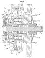
- Figs. 1 to 3 show a water pump for transmitting and blocking power through an electromagnetic clutch C according to the present invention.
- Fig. 1 is a sectional view of the water pump taken on line I-I of Fig. 2 .
- the water pump includes a pump housing 1 acting as a stationary element for supporting a shaft 3 (an example of a driven rotary element) to be rotatable about an rotational axis X through a shaft bearing 2, an impeller 4 mounted on an inner end of the shaft 3, a seal 5 disposed between the shaft 3 and the pump housing 1, and an input pulley 7 (an example of a driving rotary element) mounted on a boss portion 1A of the pump housing 1 through a pulley bearing 6 to be rotatable about the rotational axis X.
- a shaft 3 an example of a driven rotary element
- an impeller 4 mounted on an inner end of the shaft 3
- a seal 5 disposed between the shaft 3 and the pump housing 1
- an input pulley 7 an example of
- the electromagnetic clutch C is switchable between a transmission state for transmitting a rotational driving force of the input pulley 7 to the shaft 3 (clutch-engaging state) and a cutoff state for blocking the rotational drive force of the input pulley 7 (clutch-disengaging state).
- an endless belt is wound around an output pulley (not shown) mounted on an output shaft of an engine (not shown) and the input pulley 7 of the water pump, and thus the input pulley 7 is constantly driven.
- the electromagnetic clutch C is controlled through a controller (not shown) that acquires detecting results from a temperature sensor (not shown) for detecting temperature of cooling water.
- the controller is configured to set the electromagnetic clutch C to the cutoff state when it is determined that the temperature of the cooling water is low like when immediately after the engine is started (that is, a warm-up is not sufficient) to accelerate the warm-up, and to set the electromagnetic clutch C to the transmission state when it is determined that the temperature of the engine is raised to a proper level to circulate the cooling water by driving the impeller 4.
- the electromagnetic clutch C includes a coiled wrap spring 11 housed in the input pulley 7, a driving element 12, an operating element 13, an armature 15, and an electromagnetic solenoid S for exerting a drawing force to the operating element 13 to attract the same.
- the driving element 12 supports one end of the wrap spring 11 and fitted on an outer end of the shaft 3.
- the operating element 13 supports the other end of the wrap spring 11 and is rotatably mounted on an outer end of a sleeve 12S rotatable in unison with the shaft 3.
- the armature 15 is disposed between the operating element 13 and the driving element 12, and is supported to the driving element 12 through a flat spring 14 to be rotatable in unison with the driving element 12.
- a yoke 17 made of magnetic material is partially fitted into the boss portion 1A of the pump housing 1, and has a recess that is annular coaxially with the rotational axis X to be open to a direction opposite to the impeller 4.
- a coil 18 formed of a copper wire wound around a bobbin 18A is inserted into the recess of the yoke 17 to constitute the electromagnetic solenoid S.
- Attraction surfaces are formed in annular areas centering about the rotational axis X in an inner side and an outer side of the recess of the yoke 17 for receiving the coil 18.
- the wrap spring 11 is made of spirally-formed spring steel with a winding diameter to allow the spring to come into pressure contact with a cylindrical inner surface 7A of the input pulley 7 in a natural state (in which no external force is exerted).
- the driving element 12 has three arms 12A radially extending from the sleeve 12S fixedly fitted on the shaft 3 by pressure bonding.
- the one end of the wrap spring 11 is supported to one of the three arms 12A.
- the three arms 12A have retainer pieces 12B at extreme ends thereof.
- Each of the retainer pieces 12B extends in a direction parallel to the rotational axis X and one of the retainer pieces 12B is connected to the one end of the wrap spring 11.
- Limiter pieces 12C are formed in opposite ends of each retainer piece 12B for limiting expansion of the wrap spring 11 in the direction parallel to the rotational axis X. While the driving element 12 requires only one arm for supporting the one end of the wrap spring 11, the three arms 12A are provided for keeping rotational balance.
- the operating element 13 is a unit including a disk element 13D made of magnetic material and having an outer diameter equal to an outer circumference of the attraction surface of the yoke 17, and three operating arms 13A radially extending from an outer circumference of the disk element 13D and integrally formed with the disk element.
- the sleeve 12S of the driving element 12 is inserted into a through bore formed in the center of the disk element 13D to allow the operating element 13 to be rotatable relative to the sleeve 12S and movable in the direction along the rotational axis X.
- the other end of the wrap spring 11 is supported to one of the three operating arms 13A.
- the three operating arms 13A have connecting pieces 13B at extreme ends thereof.
- Each of the connecting pieces 13B extends in the direction parallel to the rotational axis X and one of the connecting pieces 13B is connected to the one end of the wrap spring 11. While the operating element 13 requires only one arm for supporting the other end of the wrap spring 11 in the similar manner to the driving element 12, the three arms 13A are provided for keeping rotational balance.
- a coil spring 16 is mounted on an outer circumference of the sleeve 12S to allow the operating arms 13A to be moved away from the yoke 17 by an urging force exerted from the coil spring 16.
- the armature 15 is a disk made of magnetic material and having an outer diameter equal to the outer circumference of the attraction surface of the yoke 17.
- the driving element 12 is mounted to face the operating element 13 across the armature 15 in the direction parallel to the rotational axis X.
- the armature 15 and the three driving arms 12A of the driving element 12 are connected through the flat springs (resilient elements) 14 (three flat springs 14 all told) to allow the armature 15 to be rotatable in unison with the sleeve 12S and movable along the rotational axis X.
- the rotational force of the driving element 12 is transmitted to the armature 15 through the three flat springs 14, and the armature 15 is maintained in a position remote from the operating element 13 with no external force being exerted and is displaced toward the operating element 13 along the rotational axis X by resilient deformation of the three flat springs 14 when the drawing force caused by a magnetic force is exerted from the operating element 13.
- the transmission state (clutch-engaging state) is achieved when the driving arms 12A of the driving element 12 and the operating arms 13A of the operating element 13 are maintained in a relative position shown in Fig. 4(a) to bring the wrap spring 11 into pressure contact with the inner surface 7A of the input pulley 7.
- the cutoff state (clutch-disengaging state) is achieved when the driving arms 12A of the driving element 12 and the operating arms 13A of the operating element 13 are moved to a relative position shown in Fig. 7(a) to allow the wrap spring 11 to move away from the inner surface 7A of the input pulley 7.
- the electromagnetic clutch C of the present invention may be configured to break the power transmission between the input pulley 7 and the shaft 3 when a pressure-contact force applied to the inner surface 7A of the input pulley 7 from the wrap spring 11 decreases. In such a case, the wrap spring 11 is in light contact with the inner surface 7A of the input pulley 7.
- the electromagnetic clutch C provides a control mechanism constituted by the driving element 12 and the operating element 13, and has restraint means for maintaining the cutoff state by setting the driving arms 12A of the driving element 12 and the operating arms 13A of the operating element 13 to the relative position shown in Fig. 7(a) .
- the operating element 13 and the armature 15 constitute the restraint means.
- a plurality of main apertures 13H are circumferentially formed in the disk 13D of the operating element 13
- a plurality of auxiliary apertures 15H are circumferentially formed in the armature 15.
- the main apertures 13H and the auxiliary apertures 15H serve to set the driving arms 12A of the driving element 12 and the operating arms 13A of the operating element 13 to the relative position shown in Fig. 7(a) when the electromagnetic clutch C is operated to the cutoff state.
- the action of the restraint means will be described below. While six main apertures 13H and six auxiliary apertures 15H are shown, the number of those apertures is not limited to six but may be selected desirably.
- the disk 13D of the operating element 13 is moved away from the yoke 17 of the electromagnetic solenoid S by the urging force of the coil spring 16 to form a clearance between the disk 3D and the yoke 17 as shown in Fig. 4(b) .
- the wrap spring 11 comes into contact with the inner surface 7A of the input pulley 7 by its own urging force (toward a radius-increasing direction) to maintain the driving arms 12A of the driving element 12 and the operating arms 13A of the operating element 13 in the relative position shown in Fig. 4(a) .
- the rotational driving force is transmitted from the driving element 12 connected to the wrap spring 11 to the shaft 3, thereby to maintain the electromagnetic clutch C in the transmission state.
- a relative angle between each driving arm 12A and each operating arm 13A maintains a transmission angle ⁇ 1 to establish a relative positional relationship in which the auxiliary apertures 15H are positioned within the main apertures 13H in the direction along the rotational axis X as shown in Fig. 4(a) .
- the disk 13D of the operating element 13 is attracted to the electromagnetic solenoid S (attraction surface of the yoke 17) against the urging force of the coil spring 16, as a result of which the operating element 13 is restrained.
- the auxiliary apertures 15H are present in an inner area of the main apertures 13H as viewed from the direction along the rotational axis X as shown in Fig. 5(a) .
- the auxiliary apertures 15H act as magnetic resistance, a density of magnetic-flux flowing from the main apertures 13H to the armature 15 is limited by the auxiliary apertures 15H.
- the driving element 12 continues to rotate in a direction shown in an arrow in Fig. 5(a) by dynamic inertia.
- the rotational force of the driving element 12 reduces the winding diameter of the wrap spring 11 and then moves the wrap spring 11 away from the inner surface 7A of the input pulley 7 as shown in Figs. 6(a) and 6(b) .
- the driving element 12 is rotated by dynamic inertia in this manner, the state in which the auxiliary apertures 15H are present within the inner area of the main apertures 13H as viewed from the direction along the rotational axis X is maintained. In this, the drawing force acting on the armature 15 is not increased, which prevents the armature 15 from being attracted to the operating element 13 as shown in Fig. 6(b) .
- the auxiliary apertures 15H are moved to an external area of the main apertures 13H (where no apertures are present) as viewed from the direction along the rotational axis X as shown in Figs. 6(a) and 7(a) to allow the relative angle between each driving arm 12A of the driving element 12 and each operating arm 13A of the operating element 13 to reach a cutoff angle ⁇ 2.
- the armature 15 is displaced along the rotational axis X and attracted to the operating element 13 as shown in Fig. 7(b) .
- the relative angle between the operating arm 13A and the driving arm 12A is changed only by a changing angle ⁇ , and the auxiliary apertures 15H are also shifted by the changing angle ⁇ relative to the main apertures 13 to allow the auxiliary apertures 15H to reach the area where no main apertures 13H are present, as a result of which the armature 15 is attracted to the operating element 13.
- the armature 15 is attracted to the operating element 13 to restrain the rotation of the driving element 12, and the relative position between the driving arms 12A of the driving element 12 and the operating arms 13A of the operating element 13 is maintained in the relationship shown in Fig. 7(b) against the urging force (toward the radius-increasing direction) of the wrap spring 11.
- This allows the wrap spring 11 to move away from the inner surface 7A of the input pulley 7 to produce the complete cutoff state.
- the rotational driving force of the input pulley 7 is not transmitted to the impeller 4, and water supply by the water pump is also stopped.
- the electric flow to the electromagnetic solenoid S is intercepted to allow the armature 15 to move away from the operating element 13 by the urging force of the flat springs 14, and to allow the operating element 13 to move away from the attraction surface of the yoke 17 by the urging force of the coil spring 16.
- the wrap spring 11 is brought into a free state, in which the winding diameter of the spring is expanded by the urging force to allow the wrap spring to come into contact with the inner surface 7A of the input pulley 7, and return to the transmission state.
- a disk-shaped lock element 21 is provided in place of the armature 15 of the above-described embodiment.
- the lock element 21 is fixed to the sleeve 12S of the driving element 12 in position, and includes engaging parts 21T having engaging teeth.
- the engaging teeth are formed in three arc areas centering about the rotational axis X in a surface of the lock element 12 facing away from the impeller 4.
- the lock element 21 may be fixedly connected to the shaft 3 directly through interdigitation, for example, or may be fixedly connected to the driving element 12 through screws 22 as shown in Fig. 8 .
- the urging force of the coil spring 16 acting as urging means is exerted on the operating element 13 to move the operating element 13 away from the electromagnetic solenoid S.
- the operating element 13 includes three engaging pawls 23 engageable with the engaging teeth of the three engaging parts 21T when the operating element 13 is attracted to the attraction surface of the yoke 17. Further, the engaging pawls 23 have spring portions 23A, respectively, that are integrally formed with the pawls at intermediate portions thereof. The spring portions 23A are resiliently deformed to allow distal ends of the engaging pawls to be displaced to some extent in an engageable or disengageable direction relative to the engaging teeth of the engaging parts 21T.
- the engaging parts 21T and the engaging pawls 23 constitute the restraint means of the present invention. More specifically, while the engaging teeth of the engaging parts 21T are formed as serration, the distal ends of the engaging pawls 23 are shaped sharp to engage with and disengage from the engaging parts 21T.
- the restraint means is configured to repeat engagement and disengagement with/from the distal ends of the engaging pawls 23 by riding over the engaging teeth when the driving element 12 is rotated by dynamic inertia with the engaging pawls 23 being engaged with the engaging parts 21T to perform the same operation as a ratchet mechanism for allowing the rotation of the driving element 12 while preventing rotation of the driving element 12 in the reverse direction.
- the operating element 13 when the operating element 13 is not attracted to the electromagnetic solenoid S, the operating element 13 is maintained in a position to come into contact with the lock element 21 by the urging force of the coil spring 16 acting as the urging means as shown in Fig. 9(b) , in which the engaging pawls 23 are maintained to be remote from the engaging parts 21 T with the operating element 13 being maintained in that position.
- the driving arms 12A of the driving element 12 and the operating arms 13A of the operating element 13 maintain the relative position shown in Fig. 9(a) to allow the electromagnetic clutch C to achieve the transmission state.
- the alternative embodiment (a) may provide any other configuration acting as the restraint means including mechanical engageable and disengageable portions.
- the engaging part 21T having numerous engaging teeth is formed in an outer circumference of the lock element
- the engaging pawl 23 is provided to move in unison with the operating element 13 when the operating element 13 is attracted to the electromagnetic solenoid S to engage with the engaging part 21T in the outer circumference of the lock element.
- only one engaging pawl 23 may be provided, or three or more engaging pawls may be provided.
- the shaft 3 (an example of a driven rotary element) is supported to the pump housing through the shaft bearing 2 to be rotatable about the rotational axis X.
- the impeller 4 is mounted on the inner end of the shaft 3, and a boss portion 12G of the driving element 12 is fitted on the outer end of the shaft 3.
- the input pulley 7 (an example of a driving rotary element) is rotatably supported to the boss portion 12G of the driving element 12 through the pulley bearing 6.
- the wrap spring 11 is provided within the input pulley 7. One end of the wrap spring 11 is supported to one of the three driving arms 12A integrally formed with the boss portion 12G of the driving element 12 as shown in Fig. 12(a) .
- the operating element 13 is supported to the boss portion 12G to be rotatable about the rotational axis X.
- the other end of the wrap spring 11 is supported to one of the three operating arms 13A integrally formed with the operating element 13.
- the input pulley 7 has the cylindrical portion 7C, and the driving arms 12A and the operating arms 13A are housed within the cylindrical portion 7.
- the yoke 17 is supported to the pump housing 1.
- the operating element 13 is arranged in a position opposite to the attraction surface of the yoke 17, and the armature 15 is arranged in an intermediate position between the operating element 13 and the driving element 12.
- the armature 15 is supported by the driving element 12 through the three flat springs 14, thereby to allow the driving element 12 and the armature 15 to be rotated in unison and movably supported along the rotational axis X.
- An urging plate 24 made of flat spring material is supported in an annular groove formed in an outer circumstance of the boss portion 12G of the driving element 12 to be rotatable about the rotational axis X.
- the urging plate 24 has three projections that are connected to the three operating arms 13A of the operating element 13 through a working rod 25.
- the operating element 13 when the electromagnetic solenoid S is not electrified, the operating element 13 is maintained in a position remote from the electromagnetic solenoid S by an urging force exerted from the urging plate 24, and the armature 15 is maintained in a position close to the driving element 12 by the urging force exerted from the flat springs 14.
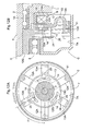
- the driving arms 12A of the driving element 12 and the operating arms 13A of the operating element 13 maintain a relative position shown in Fig. 12(a) , thereby to bring the wrap spring 11 into pressure contact with the inner surface 7A of the input pulley 7 to achieve the transmission state (clutch-engaging state).
- the operating element 13 and the armature 15 constitute the restraint means.
- the plurality of main apertures 13H are formed circumferentially in the operating element 13
- the plurality of auxiliary apertures 15H are formed circumferentially in the armature 15.
- the dimensions and the relative positional relationship of the main apertures 13H and the auxiliary apertures 15H are determined in the same manner as in the above-described embodiment.
- the driving element 12 is rotated by dynamic inertia to bring the driving arms 12A of the driving element 12 and the operating arms 13A of the operating element 13 to a relative position shown in Fig. 13(a) , thereby to move the wrap spring 11 away from the inner surface 7A of the input pulley 7.
- the armature 15 is attracted to the electromagnetic solenoid S to maintain the cutoff state as shown in Fig. 13(b) .
- the electromagnetic clutch C is formed to bring the wrap spring 11 into pressure bonding to an outer circumference of a cylindrical portion 7B formed adjacent the center of the input pulley 7.
- the electromagnetic clutch C according to the current embodiment has the same configuration as that of the above-described embodiments except for the arrangement of the wrap spring 11 coming into pressure bonding to the outer circumference of the cylindrical portion 7B.
- the wrap spring 11 as used comes into pressure bonding to the outer circumference of the cylindrical portion 7B in the natural state, and the restraint means is constituted by the operating element 13 and the armature 15.
- the armature 15 when the operating element 13 is attracted to the electromagnetic solenoid S, the armature 15 is not attracted to the operating element 13 in the area in which the auxiliary apertures15H are present within the main apertures 13H, and the driving element 12 continues to rotate by dynamic inertia.
- the auxiliary apertures 15H are moved to the external area of the main apertures 13H (where no apertures are present)
- the armature 15 is attracted to the operating element 13 to move the wrap spring 11 away from the cylindrical portion 7B of the input pulley 7, thereby to bring the electromagnetic clutch C to the cutoff state.
- the present invention is applicable to a transmission system for a radiator fan and a supercharger other than the water pump.
Landscapes
- Engineering & Computer Science (AREA)
- General Engineering & Computer Science (AREA)
- Physics & Mathematics (AREA)
- Electromagnetism (AREA)
- Mechanical Engineering (AREA)
- Mechanical Operated Clutches (AREA)
- Hydraulic Clutches, Magnetic Clutches, Fluid Clutches, And Fluid Joints (AREA)
Abstract
Description
- The present invention relates to an electromagnetic clutch, and more particularly to an electromagnetic clutch including a driving rotary element and a driven rotary element mounted coaxially with a rotational axis, and a coiled wrap spring centering about the rotational axis to establish and break power transmission by changing a winding diameter of the wrap spring.
- An example of the above-described conventional electromagnetic clutch is disclosed in
Patent Document 1, in which a driving rotary element (a first element in Patent Document 1) and a driven rotary element (a second element in Patent Document 1) are provided adjacent to each other along a rotational axis to be rotatable coaxially with the rotational axis. A wrap spring is arranged in outer circumferences of the driving rotary element and the driven rotary element. A control collar is provided around the wrap spring. One end of the wrap spring is supported to the driving rotary element and the other end of the wrap spring is supported to the control collar. - According to
Patent Document 1, a clutch-disengaging state is achieved when a magnetic force is not exerted on an armature provided in the control collar, in which the wrap spring is separated from the outer circumferences of the driving rotary element and the driven rotary element. When the magnetic force is exerted on the armature provided in the control collar to reduce a winding diameter of the wrap spring and bring the wrap spring into pressure contact with the outer circumferences of the driving rotary element and the driven rotary element, thereby to transmit a rotational driving force of the driving rotary element to the driven rotary element. - Meanwhile,
Patent Document 2 discloses an arrangement including a driving rotary element (an input pulley in Patent Document 2), a driven rotary element (an output hub in Patent Document 2), and a wrap spring provided in outer circumferences of winding surfaces of the driving rotary element and the driven rotary element. One end of the wrap spring is supported to an armature, and the other end of the wrap spring is supported to the driven rotary element. An electromagnetic solenoid is mounted within the driving rotary element for exerting a drawing force on the armature. - According to
Patent Document 2, a clutch-disengaging state is achieved when a magnetic force from the electromagnetic solenoid is not exerted on the armature, in which the wrap spring is separated from the outer circumferences of the input pulley and the output hub. When the magnetic force is exerted from the electromagnetic solenoid to the armature for drawing the armature, the wrap spring comes into tight contact with the outer circumferences of the input pulley and the output hub, thereby to transmit a driving force from the driving rotary element to the driven rotary element. -
- Patent Document 1: Japanese Unexamined Patent Application Publication No.
11-201191 - Patent Document 2: Japanese Unexamined Patent Application Publication No.
2001-317565 - As disclosed in
Patent Document 1 andPatent Document 2, in the electromagnetic clutch configured to produce the transmission state by electrifying the electromagnetic solenoid, the electrification should be continued when power is transmitted, which causes a disadvantage of waste of electric power when such an electromagnetic clutch is used in a part such as a water pump in which the transmission state (clutch-engaging state) lasts for a long period of time. In particular, in order to continuously establish reliable power transmission in the electromagnetic clutch configured to maintain the transmission state by the electrification, the electromagnetic solenoid may be large so as to cope with decrease in magnetic flux caused by increase in temperature, as a result of which the costs would be increased. Further, if the electrification is cut off by malfunction, the water pump does not function, and thus an engine may be overheated. - Taking into the above disadvantages into consideration, it is desirable to provide an electromagnetic clutch using the wrap spring configured to achieve the transmission state (clutch-engaging state) when the electromagnetic solenoid is not electrified and break the power transmission when the electromagnetic solenoid is electrified (clutch-disengaging state).
- Further, it should be noted that, in the electromagnetic clutch using the wrap spring, the armature or the like actuated by the electromagnetic solenoid is connected to one end of the wrap spring and thus only one end of the wrap spring is restrained when the electromagnetic solenoid is electrified. Therefore, an urging force continues to act on the other end of the wrap spring in a restoring direction.
- Therefore, in order to provide the electromagnetic clutch switchable to the cutoff state by electrifying the electromagnetic solenoid, the one end of the wrap spring may be restrained to a stationary element when the electromagnetic solenoid is electrified, for example. In such an arrangement, however, the wrap spring is brought into contact with an element at the driving side (such as a driving rotary element) by a restoring force exerted on the other end of the wrap spring, which brings about useless abrasion and waste of energy. Thus, there is room for improvement.
- Further, in the electromagnetic clutch disclosed in
Patent Document 1, for example, since a friction ring is provided between the electromagnetic solenoid and the armature, a large air gap is produced in that part. As a result, strict dimension control of the air gap would be required in order to exert a sufficient drawing force on the armature from the electromagnetic solenoid. In addition, a strong drawing force should be exerted on the armature, which may lead to a large-capacity electromagnetic solenoid. As a result, the entire electromagnetic clutch may easily become large and thus should desirably be miniaturized. - The object of the present invention is to provide a practical electromagnetic clutch using a wrap spring for achieving a cutoff state when an electromagnetic solenoid is switched from a non-electrified state to an electrified state and suppressing abrasion of the wrap spring and waste of energy in the cutoff state.
- A characteristic feature of the present invention lies in an electromagnetic clutch comprising a driving rotary element and a driven rotary element mounted coaxially with a rotational axis; a coiled wrap spring centering about the rotational axis; and a control mechanism for switching the electromagnetic clutch between a transmission state for bring the wrap spring into pressure contact with the driving rotary element by changing a winding diameter of the wrap spring to transmit a rotational force of the driving rotary element to the driven rotary element, and a cutoff state for decreasing the pressure contact force of the wrap spring against the driving rotary element thereby to cut off the rotational force transmitted to the driven rotary element, wherein the control mechanism includes a driving element connected to one end of the wrap spring to be rotatable in unison with the driven rotary element, an operating element made of magnetic material and connected to the other end of the wrap spring to be rotatable about the rotational axis, and an electromagnetic solenoid supported to a stationary element for attracting the operating element to restrain the operating element, and the control mechanism further includes restraint means for allowing rotation of the driving element caused by dynamic inertia after the operating element is restrained by the attraction of the electromagnetic solenoid in the transmission state to achieve a rotational phase in which the driving rotary element is brought to the cutoff state and then restraining the driving element.
- With the above-described arrangement, when the electromagnetic clutch is in the non-electrified state, the wrap spring comes into pressure contact with the driving rotary element to allow the electromagnetic clutch to be in the transmission state (clutch-engaging state), in which the rotational driving force is transmitted to the driven rotary element from the driving element connected to the one end of the wrap spring. When the electromagnetic clutch achieves the electrified state, the operating element is attracted to the electromagnetic solenoid and restrained in rotation. The driving rotary element is rotated by the dynamic inertia after the operating element is restrained to change the winding diameter of the wrap spring, thereby to achieve the cutoff state (clutch-disengaging state) for moving the wrap spring away from the contact surface of the driving rotary element. Then, the restraint means restrains the driving element. In this manner, since the one end of the wrap spring is restrained by the restraint means to inhibit the winding diameter of the wrap spring from restoring after the other end of the wrap spring is restrained by the stationary element and the cutoff state is achieved, it becomes possible to keep the wrap spring away from the driven rotary element. Further, since the operating element is attracted to the electromagnetic solenoid when electrified, no air gap is produced unlike the arrangement in which magnetic flux from the electromagnetic solenoid is exerted on the operating element through the air gap in the electrified state. Thus, the electromagnetic solenoid does not need large capacity, and can be miniaturized.
As a result, the electromagnetic clutch capable of restraining abrasion of the wrap spring and waste of energy can be miniaturized in which the electromagnetic solenoid is switched from the non-electrified state to the electrified state to move the wrap spring away from the driving rotary element to achieve the cutoff state, thereby to maintain the state in which the wrap spring is moved away from the driving rotary element. - The electromagnetic clutch according to the present invention may have the configuration in which the driven rotary element is formed as a shaft, the operating element is mounted on the shaft to be relatively rotatable and displaceable along the rotational axis, an armature made of magnetic material is provided to face the electromagnetic solenoid across the operating element to be rotatable in unison with the shaft and displaceable along the rotational axis, and the restraint means includes the operating element and the armature, in which a main aperture is formed in a surface of the operating element for attracting the electromagnetic solenoid and an auxiliary aperture is formed in a surface of the armature on which magnetic flux from the operating element is exerted, the main aperture and the auxiliary aperture achieving a positional relationship to allow a drawing force exerted on the armature to increase when the rotational phase in which the driving rotary element is brought to the cutoff state is achieved after the operating element is attracted to the electromagnetic solenoid and then attract and restrain the armature to the operating element by the increased drawing force.
- With the above-described arrangement, since the main aperture is formed in the operating element, it is possible that leakage flux is produced from the main aperture of the operating element when the operating element is attracted to the electromagnetic solenoid to exert the leakage flux on the armature. Further, due to the auxiliary aperture formed in the armature, magnetic resistance is increased and the attracting force is decreased in the area where the auxiliary aperture is formed, while the magnetic resistance is small and the attracting force is increased in the area where the auxiliary aperture is not formed. In this, after the electromagnetic solenoid is electrified and the operating element is attracted to the electromagnetic solenoid, the drawing force exerted from the operating element to the armature can be restrained during the initial stage of rotation of the driving element caused by the dynamic inertia, and then the drawing force exerted on the armature can be increased when the rotational phase in which the driving rotary element is brought to the cutoff state is achieved to attract and restrain the armature to the operating element with the wrap spring being moved away from the driven rotary element.
- The electromagnetic clutch according to the present invention may have the configuration in which the driven rotary element is formed as a shaft, the operating element is mounted on the shaft to be relatively rotatable and displaceable along the rotational axis, urging means is provided for urging the operating element in a direction to move the operating element away from the electromagnetic solenoid, a lock element is connected to the shaft to face the electromagnetic solenoid across the operating element, and the restraint means includes the lock element, and further includes an engaging part having engaging teeth formed in the lock element, and an engaging pawl engageable with the engaging part for allowing rotation of the lock element caused by the dynamic inertia when the operating element is attracted to the electromagnetic solenoid and preventing rotation in a direction to prevent the rotation of the lock element caused by an urging force of the wrap spring.
- With the above-noted arrangement, when the electromagnetic solenoid is electrified, the operating element is displaced against the urging force of the urging means to be attracted to the electromagnetic solenoid. When the operating element is displaced in this manner, the engaging pawl is displaced to the position to be engageable with the engaging teeth of the engaging part of the lock element. With this state, the engaging pawl is engaged with the engaging teeth of the engaging part. The engaging part and the engaging pawl allow the rotation of the driving element caused by the dynamic inertia, while preventing the rotation of the lock element caused by the urging force of the wrap spring. Thus, the lock element can be restrained with the wrap spring being moved away from the driven rotary element.
- The electromagnetic clutch according to the present invention may have the configuration in which the driving rotary element has a cylindrical inner surface, and the wrap spring comes into pressure contact with the inner surface in a natural state.
- With the above-described arrangement, when a pulley is used as the driving rotary element, for example, it is possible to provide the electromagnetic clutch using the cylindrical inner surface of the pulley and having the wrap spring coming into contact with the inner surface in the natural state.
- The electromagnetic clutch according to the present invention may have the configuration in which the driving element includes a driving arm extending radially from the rotational axis, the driving arm has a retainer piece at an extreme end thereof, the retainer piece extending in a direction parallel to the rotation axis, the operating element includes an operating arm extending radially from the rotational axis, the operating arm has a connecting piece at en extreme end thereof, the connecting piece extending in the direction parallel to the rotational axis, and the retainer piece is connected to the one end of the wrap spring while the connecting piece is connected to the other end of the wrap spring.
- The electromagnetic clutch according to the present invention may have the configuration in which the driving rotary element has a cylindrical portion, and at least one of the driving arm and the operating arm is housed within the cylindrical portion.
- The electromagnetic clutch according to the present invention may have the configuration in which the driving rotary element has a cylindrical portion, and the armature is housed within the cylindrical portion.
- The electromagnetic clutch according to the present invention may have the configuration in which the retainer piece is provided with limiter pieces for limiting expansion of the wrap spring in the direction parallel to the rotational axis.
- The electromagnetic clutch according to the present invention may have the configuration in which the limiter pieces project toward the wrap spring.
- The electromagnetic clutch according to the present invention may have the configuration in which the limiter pieces are provided in opposite sides of the wrap spring in the direction parallel to the rotational axis.
- The electromagnetic clutch according to the present invention may have the configuration in which the operating element is attracted to the electromagnetic solenoid with the auxiliary aperture being positioned within an area of the main aperture and then the auxiliary aperture is moved out of the area of the main aperture, thereby to increase the drawing force exerted on the armature to attract the armature to the operating element.
- The electromagnetic clutch according to the present invention may have the configuration in which the driving element is provided to face the operating element across the armature in the direction parallel to the rotational axis, the armature is connected to the driving element through a resilient element, thereby to transmit a rotational force of the driving element to the armature and to urge the armature in a direction to move the armature away from the electromagnetic solenoid, the drawing force of the solenoid exerted on the armature with the auxiliary aperture being positioned within the area of the main aperture is smaller than an urging force of the resilient element, and the drawing force of the solenoid exerted on the armature with the auxiliary aperture being positioned out of the area of the main aperture is greater than the urging force of the resilient element.
- The electromagnetic clutch according to the present invention may have the configuration in which the engaging teeth are formed in arc areas centering about the rotational axis in a surface of the lock element facing away from the operating element.
- The electromagnetic clutch according to the present invention may have the configuration in which the engaging teeth are formed in an outer circumference of the lock element.
-
-
Fig. 1 is a sectional view of a water pump including an electromagnetic clutch; -
Fig. 2 is a front view of the electromagnetic clutch; -
Fig. 3 is an exploded perspective view of the electromagnetic clutch; -
Fig. 4 is a front view of the electromagnetic clutch in a transmission state and a sectional view taken on line b-b of the front view; -
Fig. 5 is a front view of the electromagnetic clutch with an operating element being attracted to an electromagnetic solenoid and a sectional view taken on line b-b of the front view; -
Fig. 6 is a front view of the electromagnetic clutch with a driving member being rotated by dynamic inertia and a sectional view taken on line b-b of the front view; -
Fig. 7 is a front view of the electromagnetic clutch with an armature being attracted to the operating element and a sectional view taken on line b-b of the front view; -
Fig. 8 is a sectional view of a water pump including an electromagnetic clutch according to a modified embodiment (a); -
Fig. 9 is a front view of the electromagnetic clutch in the transmission state in the modified embodiment (a) and a sectional view taken on line b-b of the front view; -
Fig. 10 is a front view of the electromagnetic clutch with an operating element being attracted to an electromagnetic solenoid in a modified embodiment (b) and a sectional view taken on line b-b of the front view; -
Fig. 11 is a sectional view of a water pump including an electromagnetic clutch according to a modified embodiment (b); -
Fig. 12 is a front view of the electromagnetic clutch in the transmission state in the modified embodiment (b) and a partial sectional view of the front view; -
Fig. 13 is a front view of the electromagnetic clutch with the armature being attracted to the operating element in the modified embodiment (b) and a partial sectional view of the front view; and -
Fig. 14 is a sectional view of a water pump including an electromagnetic clutch according to a modified embodiment (c). - Embodiments of the present invention will be described hereinafter in reference to the accompanying drawings.
-
Figs. 1 to 3 show a water pump for transmitting and blocking power through an electromagnetic clutch C according to the present invention.Fig. 1 is a sectional view of the water pump taken on line I-I ofFig. 2 . The water pump includes apump housing 1 acting as a stationary element for supporting a shaft 3 (an example of a driven rotary element) to be rotatable about an rotational axis X through ashaft bearing 2, animpeller 4 mounted on an inner end of theshaft 3, aseal 5 disposed between theshaft 3 and thepump housing 1, and an input pulley 7 (an example of a driving rotary element) mounted on aboss portion 1A of thepump housing 1 through a pulley bearing 6 to be rotatable about the rotational axis X. The electromagnetic clutch C is switchable between a transmission state for transmitting a rotational driving force of theinput pulley 7 to the shaft 3 (clutch-engaging state) and a cutoff state for blocking the rotational drive force of the input pulley 7 (clutch-disengaging state). - During use of the water pump, an endless belt is wound around an output pulley (not shown) mounted on an output shaft of an engine (not shown) and the
input pulley 7 of the water pump, and thus theinput pulley 7 is constantly driven. The electromagnetic clutch C is controlled through a controller (not shown) that acquires detecting results from a temperature sensor (not shown) for detecting temperature of cooling water. The controller is configured to set the electromagnetic clutch C to the cutoff state when it is determined that the temperature of the cooling water is low like when immediately after the engine is started (that is, a warm-up is not sufficient) to accelerate the warm-up, and to set the electromagnetic clutch C to the transmission state when it is determined that the temperature of the engine is raised to a proper level to circulate the cooling water by driving theimpeller 4. - The electromagnetic clutch C includes a coiled
wrap spring 11 housed in theinput pulley 7, a drivingelement 12, an operatingelement 13, anarmature 15, and an electromagnetic solenoid S for exerting a drawing force to theoperating element 13 to attract the same. The drivingelement 12 supports one end of thewrap spring 11 and fitted on an outer end of theshaft 3. The operatingelement 13 supports the other end of thewrap spring 11 and is rotatably mounted on an outer end of asleeve 12S rotatable in unison with theshaft 3. Thearmature 15 is disposed between the operatingelement 13 and the drivingelement 12, and is supported to the drivingelement 12 through aflat spring 14 to be rotatable in unison with the drivingelement 12. - A
yoke 17 made of magnetic material is partially fitted into theboss portion 1A of thepump housing 1, and has a recess that is annular coaxially with the rotational axis X to be open to a direction opposite to theimpeller 4. Acoil 18 formed of a copper wire wound around abobbin 18A is inserted into the recess of theyoke 17 to constitute the electromagnetic solenoid S. Attraction surfaces are formed in annular areas centering about the rotational axis X in an inner side and an outer side of the recess of theyoke 17 for receiving thecoil 18. Thewrap spring 11 is made of spirally-formed spring steel with a winding diameter to allow the spring to come into pressure contact with a cylindricalinner surface 7A of theinput pulley 7 in a natural state (in which no external force is exerted). - The driving
element 12 has threearms 12A radially extending from thesleeve 12S fixedly fitted on theshaft 3 by pressure bonding. The one end of thewrap spring 11 is supported to one of the threearms 12A. The threearms 12A haveretainer pieces 12B at extreme ends thereof. Each of theretainer pieces 12B extends in a direction parallel to the rotational axis X and one of theretainer pieces 12B is connected to the one end of thewrap spring 11.Limiter pieces 12C are formed in opposite ends of eachretainer piece 12B for limiting expansion of thewrap spring 11 in the direction parallel to the rotational axis X. While the drivingelement 12 requires only one arm for supporting the one end of thewrap spring 11, the threearms 12A are provided for keeping rotational balance. - The operating
element 13 is a unit including adisk element 13D made of magnetic material and having an outer diameter equal to an outer circumference of the attraction surface of theyoke 17, and three operatingarms 13A radially extending from an outer circumference of thedisk element 13D and integrally formed with the disk element. Thesleeve 12S of the drivingelement 12 is inserted into a through bore formed in the center of thedisk element 13D to allow theoperating element 13 to be rotatable relative to thesleeve 12S and movable in the direction along the rotational axis X. The other end of thewrap spring 11 is supported to one of the three operatingarms 13A. The three operatingarms 13A have connectingpieces 13B at extreme ends thereof. Each of the connectingpieces 13B extends in the direction parallel to the rotational axis X and one of the connectingpieces 13B is connected to the one end of thewrap spring 11. While the operatingelement 13 requires only one arm for supporting the other end of thewrap spring 11 in the similar manner to the drivingelement 12, the threearms 13A are provided for keeping rotational balance. In addition, acoil spring 16 is mounted on an outer circumference of thesleeve 12S to allow the operatingarms 13A to be moved away from theyoke 17 by an urging force exerted from thecoil spring 16. - The
armature 15 is a disk made of magnetic material and having an outer diameter equal to the outer circumference of the attraction surface of theyoke 17. The drivingelement 12 is mounted to face the operatingelement 13 across thearmature 15 in the direction parallel to the rotational axis X. Thearmature 15 and the three drivingarms 12A of the drivingelement 12 are connected through the flat springs (resilient elements) 14 (threeflat springs 14 all told) to allow thearmature 15 to be rotatable in unison with thesleeve 12S and movable along the rotational axis X. More particularly, the rotational force of the drivingelement 12 is transmitted to thearmature 15 through the threeflat springs 14, and thearmature 15 is maintained in a position remote from the operatingelement 13 with no external force being exerted and is displaced toward the operatingelement 13 along the rotational axis X by resilient deformation of the threeflat springs 14 when the drawing force caused by a magnetic force is exerted from the operatingelement 13. - In the electromagnetic clutch C of the present invention, the transmission state (clutch-engaging state) is achieved when the driving
arms 12A of the drivingelement 12 and the operatingarms 13A of the operatingelement 13 are maintained in a relative position shown inFig. 4(a) to bring thewrap spring 11 into pressure contact with theinner surface 7A of theinput pulley 7. Conversely, the cutoff state (clutch-disengaging state) is achieved when the drivingarms 12A of the drivingelement 12 and the operatingarms 13A of the operatingelement 13 are moved to a relative position shown inFig. 7(a) to allow thewrap spring 11 to move away from theinner surface 7A of theinput pulley 7. It should be noted that it is not required that thewrap spring 11 be completely separated from theinner surface 7A of theinput pulley 7 in the cutoff state. For example, the electromagnetic clutch C of the present invention may be configured to break the power transmission between theinput pulley 7 and theshaft 3 when a pressure-contact force applied to theinner surface 7A of theinput pulley 7 from thewrap spring 11 decreases. In such a case, thewrap spring 11 is in light contact with theinner surface 7A of theinput pulley 7. - In particular, the electromagnetic clutch C provides a control mechanism constituted by the driving
element 12 and the operatingelement 13, and has restraint means for maintaining the cutoff state by setting the drivingarms 12A of the drivingelement 12 and the operatingarms 13A of the operatingelement 13 to the relative position shown inFig. 7(a) . - The operating
element 13 and thearmature 15 constitute the restraint means.
As shown inFig. 3 andFig. 4(a) , while a plurality ofmain apertures 13H are circumferentially formed in thedisk 13D of the operatingelement 13, a plurality ofauxiliary apertures 15H are circumferentially formed in thearmature 15. Themain apertures 13H and theauxiliary apertures 15H serve to set the drivingarms 12A of the drivingelement 12 and the operatingarms 13A of the operatingelement 13 to the relative position shown inFig. 7(a) when the electromagnetic clutch C is operated to the cutoff state. The action of the restraint means will be described below. While sixmain apertures 13H and sixauxiliary apertures 15H are shown, the number of those apertures is not limited to six but may be selected desirably. - When the electromagnetic solenoid S is not electrified, the
disk 13D of the operatingelement 13 is moved away from theyoke 17 of the electromagnetic solenoid S by the urging force of thecoil spring 16 to form a clearance between the disk 3D and theyoke 17 as shown inFig. 4(b) . In such a state, thewrap spring 11 comes into contact with theinner surface 7A of theinput pulley 7 by its own urging force (toward a radius-increasing direction) to maintain the drivingarms 12A of the drivingelement 12 and the operatingarms 13A of the operatingelement 13 in the relative position shown inFig. 4(a) . As a result, the rotational driving force is transmitted from the drivingelement 12 connected to thewrap spring 11 to theshaft 3, thereby to maintain the electromagnetic clutch C in the transmission state. - In the transmission state, a relative angle between each driving
arm 12A and eachoperating arm 13A maintains a transmission angle θ1 to establish a relative positional relationship in which theauxiliary apertures 15H are positioned within themain apertures 13H in the direction along the rotational axis X as shown inFig. 4(a) . - Next, when the
coil 18 of the electromagnetic solenoid S is electrified, thedisk 13D of the operatingelement 13 is attracted to the electromagnetic solenoid S (attraction surface of the yoke 17) against the urging force of thecoil spring 16, as a result of which theoperating element 13 is restrained. When thedisk 13D is attracted in this manner, theauxiliary apertures 15H are present in an inner area of themain apertures 13H as viewed from the direction along the rotational axis X as shown inFig. 5(a) . In this positional relationship, since theauxiliary apertures 15H act as magnetic resistance, a density of magnetic-flux flowing from themain apertures 13H to thearmature 15 is limited by theauxiliary apertures 15H. In the electromagnetic clutch C of the present invention, a relationship is established so that the drawing force acting on thearmature 15 becomes smaller than the urging force acting for moving thearmature 15 from the threeflat springs 14 due to the restricted magnetic-flux density, as a result of which thearmature 15 is not attracted to theoperating element 13. - After the rotation of the operating
element 13 is restrained, the drivingelement 12 continues to rotate in a direction shown in an arrow inFig. 5(a) by dynamic inertia. The rotational force of the drivingelement 12 reduces the winding diameter of thewrap spring 11 and then moves thewrap spring 11 away from theinner surface 7A of theinput pulley 7 as shown inFigs. 6(a) and 6(b) . When the drivingelement 12 is rotated by dynamic inertia in this manner, the state in which theauxiliary apertures 15H are present within the inner area of themain apertures 13H as viewed from the direction along the rotational axis X is maintained. In this, the drawing force acting on thearmature 15 is not increased, which prevents thearmature 15 from being attracted to theoperating element 13 as shown inFig. 6(b) . - With such rotation, the
auxiliary apertures 15H are moved to an external area of themain apertures 13H (where no apertures are present) as viewed from the direction along the rotational axis X as shown inFigs. 6(a) and7(a) to allow the relative angle between each drivingarm 12A of the drivingelement 12 and eachoperating arm 13A of the operatingelement 13 to reach a cutoff angle θ2. When the relative angle reaches the cutoff angle θ2, thearmature 15 is displaced along the rotational axis X and attracted to theoperating element 13 as shown inFig. 7(b) . More particularly, in this positional relationship, magnetic resistance exerted on the magnetic flux flowing from themain apertures 13H to thearmature 15 acting as leakage flux becomes a minimum value, and the density of magnetic flux flowing to thearmature 15 is intensified to increase the drawing force. Then, the drawing force acting on thearmature 15 becomes greater than the urging force acting for moving thearmature 15 from the threeflat springs 14, as a result of which thearmature 15 is attracted to theoperating element 13. - In achieving the cutoff state, the relative angle between the operating
arm 13A and the drivingarm 12A is changed only by a changing angle α, and theauxiliary apertures 15H are also shifted by the changing angle α relative to themain apertures 13 to allow theauxiliary apertures 15H to reach the area where nomain apertures 13H are present, as a result of which thearmature 15 is attracted to theoperating element 13. - In this manner, the
armature 15 is attracted to theoperating element 13 to restrain the rotation of the drivingelement 12, and the relative position between the drivingarms 12A of the drivingelement 12 and the operatingarms 13A of the operatingelement 13 is maintained in the relationship shown inFig. 7(b) against the urging force (toward the radius-increasing direction) of thewrap spring 11. This allows thewrap spring 11 to move away from theinner surface 7A of theinput pulley 7 to produce the complete cutoff state. In the cutoff state, the rotational driving force of theinput pulley 7 is not transmitted to theimpeller 4, and water supply by the water pump is also stopped. - Then, the electric flow to the electromagnetic solenoid S is intercepted to allow the
armature 15 to move away from the operatingelement 13 by the urging force of theflat springs 14, and to allow theoperating element 13 to move away from the attraction surface of theyoke 17 by the urging force of thecoil spring 16. In this, thewrap spring 11 is brought into a free state, in which the winding diameter of the spring is expanded by the urging force to allow the wrap spring to come into contact with theinner surface 7A of theinput pulley 7, and return to the transmission state. - The present invention is not limited to the above-described embodiment and may be modified as set forth below. In the alternative embodiments, like reference numerals are used to designate elements having like functions as in the above-described embodiment.
- (a) As illustrated in
Fig. 8 , a disk-shapedlock element 21 is provided in place of thearmature 15 of the above-described embodiment. Thelock element 21 is fixed to thesleeve 12S of the drivingelement 12 in position, and includes engagingparts 21T having engaging teeth. The engaging teeth are formed in three arc areas centering about the rotational axis X in a surface of thelock element 12 facing away from theimpeller 4. Thelock element 21 may be fixedly connected to theshaft 3 directly through interdigitation, for example, or may be fixedly connected to the drivingelement 12 throughscrews 22 as shown inFig. 8 . - The urging force of the
coil spring 16 acting as urging means is exerted on the operatingelement 13 to move the operatingelement 13 away from the electromagnetic solenoid S. The operatingelement 13 includes three engagingpawls 23 engageable with the engaging teeth of the three engagingparts 21T when the operatingelement 13 is attracted to the attraction surface of theyoke 17. Further, the engagingpawls 23 havespring portions 23A, respectively, that are integrally formed with the pawls at intermediate portions thereof. Thespring portions 23A are resiliently deformed to allow distal ends of the engaging pawls to be displaced to some extent in an engageable or disengageable direction relative to the engaging teeth of the engagingparts 21T. - In the alternative embodiment (a), the engaging
parts 21T and the engagingpawls 23 constitute the restraint means of the present invention. More specifically, while the engaging teeth of the engagingparts 21T are formed as serration, the distal ends of the engagingpawls 23 are shaped sharp to engage with and disengage from the engagingparts 21T. The restraint means is configured to repeat engagement and disengagement with/from the distal ends of the engagingpawls 23 by riding over the engaging teeth when the drivingelement 12 is rotated by dynamic inertia with the engagingpawls 23 being engaged with the engagingparts 21T to perform the same operation as a ratchet mechanism for allowing the rotation of the drivingelement 12 while preventing rotation of the drivingelement 12 in the reverse direction. - Therefore, when the operating
element 13 is not attracted to the electromagnetic solenoid S, the operatingelement 13 is maintained in a position to come into contact with thelock element 21 by the urging force of thecoil spring 16 acting as the urging means as shown inFig. 9(b) , in which the engagingpawls 23 are maintained to be remote from the engagingparts 21 T with the operatingelement 13 being maintained in that position. In this positional relationship, the drivingarms 12A of the drivingelement 12 and the operatingarms 13A of the operatingelement 13 maintain the relative position shown inFig. 9(a) to allow the electromagnetic clutch C to achieve the transmission state. - When the electromagnetic solenoid S is electrified to allow the
operating element 13 to be attracted to the electromagnetic solenoid S as shown inFig. 10(b) , the engagingpawls 23 are brought into engagement with the engagingparts 21T of thelock element 21, and the restraint means allows the rotation of the drivingelement 12 by dynamic inertia. Then, the rotation of the drivingelement 12 is stopped when the reverse rotational force caused by the urging force of thewrap spring 11 balances with the dynamic inertia to bring the engagingpawls 23 into engagement with the engagingparts 21T, thereby to prevent the reverse rotation of the drivingelement 12. When the rotation is stopped, the drivingarms 12A of the drivingelement 12 and the operatingarms 13A of the operatingelement 13 achieve the relative position shown inFig. 10(a) to maintain the electromagnetic clutch C in the cutoff state in which thewrap spring 11 is moved away from theinner surface 7A of theinput pulley 7. - The alternative embodiment (a) may provide any other configuration acting as the restraint means including mechanical engageable and disengageable portions. For instance, while the
engaging part 21T having numerous engaging teeth is formed in an outer circumference of the lock element, the engagingpawl 23 is provided to move in unison with the operatingelement 13 when the operatingelement 13 is attracted to the electromagnetic solenoid S to engage with theengaging part 21T in the outer circumference of the lock element. In this alternative embodiment (a), only one engagingpawl 23 may be provided, or three or more engaging pawls may be provided. - (b) As shown in
Fig. 11 , the shaft 3 (an example of a driven rotary element) is supported to the pump housing through theshaft bearing 2 to be rotatable about the rotational axis X. Theimpeller 4 is mounted on the inner end of theshaft 3, and aboss portion 12G of the drivingelement 12 is fitted on the outer end of theshaft 3. The input pulley 7 (an example of a driving rotary element) is rotatably supported to theboss portion 12G of the drivingelement 12 through the pulley bearing 6. Thewrap spring 11 is provided within theinput pulley 7. One end of thewrap spring 11 is supported to one of the three drivingarms 12A integrally formed with theboss portion 12G of the drivingelement 12 as shown inFig. 12(a) . The operatingelement 13 is supported to theboss portion 12G to be rotatable about the rotational axis X. The other end of thewrap spring 11 is supported to one of the three operatingarms 13A integrally formed with the operatingelement 13. Theinput pulley 7 has thecylindrical portion 7C, and the drivingarms 12A and the operatingarms 13A are housed within thecylindrical portion 7. - The
yoke 17 is supported to thepump housing 1. The operatingelement 13 is arranged in a position opposite to the attraction surface of theyoke 17, and thearmature 15 is arranged in an intermediate position between the operatingelement 13 and the drivingelement 12. Thearmature 15 is supported by the drivingelement 12 through the threeflat springs 14, thereby to allow the drivingelement 12 and thearmature 15 to be rotated in unison and movably supported along the rotational axis X. An urgingplate 24 made of flat spring material is supported in an annular groove formed in an outer circumstance of theboss portion 12G of the drivingelement 12 to be rotatable about the rotational axis X. The urgingplate 24 has three projections that are connected to the three operatingarms 13A of the operatingelement 13 through a workingrod 25. - With such an arrangement, when the electromagnetic solenoid S is not electrified, the operating
element 13 is maintained in a position remote from the electromagnetic solenoid S by an urging force exerted from the urgingplate 24, and thearmature 15 is maintained in a position close to the drivingelement 12 by the urging force exerted from the flat springs 14. In this state, the drivingarms 12A of the drivingelement 12 and the operatingarms 13A of the operatingelement 13 maintain a relative position shown inFig. 12(a) , thereby to bring thewrap spring 11 into pressure contact with theinner surface 7A of theinput pulley 7 to achieve the transmission state (clutch-engaging state). - In the alternative embodiment (b) as well, the operating
element 13 and thearmature 15 constitute the restraint means. In the same manner as the above-described embodiment, while the plurality ofmain apertures 13H are formed circumferentially in theoperating element 13, the plurality ofauxiliary apertures 15H are formed circumferentially in thearmature 15. The dimensions and the relative positional relationship of themain apertures 13H and theauxiliary apertures 15H are determined in the same manner as in the above-described embodiment. When thecoil 18 of the electromagnetic solenoid S is electrified, the operatingelement 13 is attracted to the electromagnetic solenoid S to restrain the other end of thewrap spring 11. Then, the drivingelement 12 is rotated by dynamic inertia to bring the drivingarms 12A of the drivingelement 12 and the operatingarms 13A of the operatingelement 13 to a relative position shown inFig. 13(a) , thereby to move thewrap spring 11 away from theinner surface 7A of theinput pulley 7. In this state, thearmature 15 is attracted to the electromagnetic solenoid S to maintain the cutoff state as shown inFig. 13(b) . - (c) As illustrated in
Fig. 14 , the electromagnetic clutch C is formed to bring thewrap spring 11 into pressure bonding to an outer circumference of acylindrical portion 7B formed adjacent the center of theinput pulley 7. The electromagnetic clutch C according to the current embodiment has the same configuration as that of the above-described embodiments except for the arrangement of thewrap spring 11 coming into pressure bonding to the outer circumference of thecylindrical portion 7B. Naturally, thewrap spring 11 as used comes into pressure bonding to the outer circumference of thecylindrical portion 7B in the natural state, and the restraint means is constituted by the operatingelement 13 and thearmature 15. - With the above-described arrangement, when the operating
element 13 is attracted to the electromagnetic solenoid S, thearmature 15 is not attracted to theoperating element 13 in the area in which the auxiliary apertures15H are present within themain apertures 13H, and the drivingelement 12 continues to rotate by dynamic inertia. When theauxiliary apertures 15H are moved to the external area of themain apertures 13H (where no apertures are present), thearmature 15 is attracted to theoperating element 13 to move thewrap spring 11 away from thecylindrical portion 7B of theinput pulley 7, thereby to bring the electromagnetic clutch C to the cutoff state. - The present invention is applicable to a transmission system for a radiator fan and a supercharger other than the water pump.
Claims (15)
- An electromagnetic clutch comprising:a driving rotary element and a driven rotary element mounted coaxially with a rotational axis;a coiled wrap spring centering about the rotational axis; anda control mechanism for switching the electromagnetic clutch between a transmission state for bring the wrap spring into pressure contact with the driving rotary element by changing a winding diameter of the wrap spring to transmit a rotational force of the driving rotary element to the driven rotary element, and a cutoff state for decreasing the pressure contact force of the wrap spring against the driving rotary element thereby to cut off the rotational force transmitted to the driven rotary element;wherein the control mechanism includes a driving element connected to one end of the wrap spring to be rotatable in unison with the driven rotary element, an operating element made of magnetic material and connected to the other end of the wrap spring to be rotatable about the rotational axis, and an electromagnetic solenoid supported to a stationary element for attracting the operating element to restrain the operating element, andthe control mechanism further includes restraint means for allowing rotation of the driving element caused by dynamic inertia after the operating element is restrained by the attraction of the electromagnetic solenoid in the transmission state to achieve a rotational phase in which the driving rotary element is brought to the cutoff state and then restraining the driving element.
- The electromagnetic clutch according to claim 1, wherein the driven rotary element is formed as a shaft,
the operating element is mounted on the shaft to be relatively rotatable and displaceable along the rotational axis,
an armature made of magnetic material is provided to face the electromagnetic solenoid across the operating element to be rotatable in unison with the shaft and displaceable along the rotational axis, and
the restraint means includes the operating element and the armature, in which a main aperture is formed in a surface of the operating element for attracting the electromagnetic solenoid and an auxiliary aperture is formed in a surface of the armature on which magnetic flux from the operating element is exerted, the main aperture and the auxiliary aperture achieving a positional relationship to allow a drawing force exerted on the armature to increase when the rotational phase in which the driving rotary element is brought to the cutoff state is achieved after the operating element is attracted to the electromagnetic solenoid and then attract and restrain the armature to the operating element by the increased drawing force. - The electromagnetic clutch according to claim 1, wherein the driven rotary element is formed as a shaft,
the operating element is mounted on the shaft to be relatively rotatable and displaceable along the rotational axis,
urging means is provided for urging the operating element in a direction to move the operating element away from the electromagnetic solenoid,
a lock element is connected to the shaft to face the electromagnetic solenoid across the operating element, and
the restraint means includes the lock element, and further includes an engaging part having engaging teeth formed in the lock element, and an engaging pawl engageable with the engaging part for allowing rotation of the lock element caused by the dynamic inertia when the operating element is attracted to the electromagnetic solenoid and preventing rotation in a direction to prevent the rotation of the lock element caused by an urging force of the wrap spring. - The electromagnetic clutch according to any one of claims 1 to 3, wherein the driving rotary element has a cylindrical inner surface, and the wrap spring comes into pressure contact with the inner surface in a natural state.
- The electromagnetic clutch according to claim 1 or 3, wherein the driving element includes a driving arm extending radially from the rotational axis,
the driving arm has a retainer piece at an extreme end thereof, the retainer piece extending in a direction parallel to the rotation axis,
the operating element includes an operating arm extending radially from the rotational axis,
the operating arm has a connecting piece at en extreme end thereof, the connecting piece extending in the direction parallel to the rotational axis, and
the retainer piece is connected to the one end of the wrap spring while the connecting piece is connected to the other end of the wrap spring. - The electromagnetic clutch according to claim 2, wherein the driving element includes a driving arm extending radially from the rotational axis,
the driving arm has a retainer piece at an extreme end thereof, the retainer piece extending in a direction parallel to the rotation axis,
the operating element includes an operating arm extending radially from the rotational axis,
the operating arm has a connecting piece at en extreme end thereof, the connecting piece extending in the direction parallel to the rotational axis, and
the retainer piece is connected to the one end of the wrap spring while the connecting piece is connected to the other end of the wrap spring. - The electromagnetic clutch according to claim 6, wherein the driving rotary element has a cylindrical portion, and at least one of the driving arm and the operating arm is housed within the cylindrical portion.
- The electromagnetic clutch according to claim 6 or 7, wherein the driving rotary element has a cylindrical portion, and the armature is housed within the cylindrical portion.
- The electromagnetic clutch according to any one of claims 5 to 8, wherein the retainer piece is provided with limiter pieces for limiting expansion of the wrap spring in the direction parallel to the rotational axis.
- The electromagnetic clutch according to claim 9, wherein the limiter pieces project toward the wrap spring.
- The electromagnetic clutch according to claim 9 or 10, wherein the limiter pieces are provided in opposite sides of the wrap spring in the direction parallel to the rotational axis.
- The electromagnetic clutch according to claim 2, wherein the operating element is attracted to the electromagnetic solenoid with the auxiliary aperture being positioned within an area of the main aperture and then the auxiliary aperture is moved out of the area of the main aperture, thereby to increase the drawing force exerted on the armature to attract the armature to the operating element.
- The electromagnetic clutch according to claim 12, wherein the driving element is provided to face the operating element across the armature in the direction parallel to the rotational axis,
the armature is connected to the driving element through a resilient element, thereby to transmit a rotational force of the driving element to the armature and to urge the armature in a direction to move the armature away from the electromagnetic solenoid,
the drawing force of the solenoid exerted on the armature with the auxiliary aperture being positioned within the area of the main aperture is smaller than an urging force of the resilient element, and
the drawing force of the solenoid exerted on the armature with the auxiliary aperture being positioned out of the area of the main aperture is greater than the urging force of the resilient element. - The electromagnetic clutch according to claim 3, wherein the engaging teeth are formed in arc areas centering about the rotational axis in a surface of the lock element facing away from the operating element.
- The electromagnetic clutch according to claim 3, wherein the engaging teeth are formed in an outer circumference of the lock element.
Applications Claiming Priority (3)
| Application Number | Priority Date | Filing Date | Title |
|---|---|---|---|
| JP2011099898 | 2011-04-27 | ||
| JP2011244749A JP5257716B2 (en) | 2011-11-08 | 2011-11-08 | Electromagnetic clutch |
| PCT/JP2012/059788 WO2012147510A1 (en) | 2011-04-27 | 2012-04-10 | Electromagnetic clutch |
Publications (3)
| Publication Number | Publication Date |
|---|---|
| EP2669542A1 true EP2669542A1 (en) | 2013-12-04 |
| EP2669542A4 EP2669542A4 (en) | 2015-07-15 |
| EP2669542B1 EP2669542B1 (en) | 2016-07-06 |
Family
ID=47072033
Family Applications (1)
| Application Number | Title | Priority Date | Filing Date |
|---|---|---|---|
| EP12776307.6A Not-in-force EP2669542B1 (en) | 2011-04-27 | 2012-04-10 | Electromagnetic clutch |
Country Status (4)
| Country | Link |
|---|---|
| US (1) | US9140314B2 (en) |
| EP (1) | EP2669542B1 (en) |
| CN (1) | CN103415721B (en) |
| WO (1) | WO2012147510A1 (en) |
Families Citing this family (9)
| Publication number | Priority date | Publication date | Assignee | Title |
|---|---|---|---|---|
| JP5626595B2 (en) * | 2011-04-27 | 2014-11-19 | アイシン精機株式会社 | Electromagnetic clutch |
| WO2013003937A1 (en) | 2011-05-13 | 2013-01-10 | Litens Automotive Partnership | Intelligent belt drive system and method |
| EP2592296B1 (en) * | 2011-11-09 | 2014-01-15 | Aisin Seiki Kabushiki Kaisha | Electromagnetic clutch |
| US10670021B2 (en) | 2014-01-10 | 2020-06-02 | Litens Automotive Partnership | Control of clutched device using magnetic force from motor |
| US10197134B2 (en) | 2014-09-30 | 2019-02-05 | Ford Global Technologies, Llc | Hybrid transmission having electro-magnetically actuated pawl clutch |
| US10145444B2 (en) * | 2016-07-25 | 2018-12-04 | Ford Global Technologies, Llc | Systems for a crankshaft damper cover |
| CN206277947U (en) * | 2016-09-28 | 2017-06-27 | 精进电动科技股份有限公司 | A kind of vehicle electrical drive assembly |
| GB2577096B (en) * | 2018-09-13 | 2021-06-02 | Ford Global Tech Llc | A pulley insert |
| IT202000002686A1 (en) * | 2020-02-11 | 2021-08-11 | Dayco Europe Srl | PULLEY GROUP FOR A MOTOR OF A MOTOR VEHICLE |
Family Cites Families (15)
| Publication number | Priority date | Publication date | Assignee | Title |
|---|---|---|---|---|
| AU4791279A (en) * | 1978-06-12 | 1979-12-20 | Diesel Kiki Co. Ltd. | Clutch |
| JPS58134235A (en) * | 1982-02-03 | 1983-08-10 | Nissan Motor Co Ltd | Mechanical electromagnetic clutch |
| JPH0348421Y2 (en) * | 1986-12-05 | 1991-10-16 | ||
| JPH03129130A (en) | 1989-10-13 | 1991-06-03 | Mita Ind Co Ltd | Electromagnetic control spring clutch mechanism |
| US5967274A (en) | 1997-10-21 | 1999-10-19 | Dana Corporation | Wrap spring clutch/brake assembly having soft start and soft stop capabilities |
| FR2796435B1 (en) | 1999-07-12 | 2008-08-01 | Luk Getriebe Systeme Gmbh | GENERATING TRAINING OF A RELATIVE DISPLACEMENT OF TWO COMPONENTS |
| JP2001317565A (en) | 2000-05-11 | 2001-11-16 | Toyota Industries Corp | Electromagnetic spring clutch |
| NL1019770C2 (en) | 2002-01-17 | 2003-07-18 | Skf Ab | Electrically operated coupling with multiple start / generator means. |
| JP4771286B2 (en) | 2005-09-30 | 2011-09-14 | 日立工機株式会社 | Electric nailer |
| JP4752664B2 (en) * | 2006-08-04 | 2011-08-17 | 株式会社豊田自動織機 | Power transmission mechanism |
| PL2347143T3 (en) * | 2008-11-17 | 2015-06-30 | Litens Automotive Inc | A helical coil clutch assembly comprising an actuator to effect engagement of helical coil clutch with a clutch surface |
| CN201428759Y (en) | 2009-06-24 | 2010-03-24 | 迟国君 | Electromagnetic clutch with automatic overload disengagement of automobile air conditioner |
| JP2011220326A (en) | 2010-03-25 | 2011-11-04 | Aisin Seiki Co Ltd | Water pump for vehicle |
| JP5626595B2 (en) * | 2011-04-27 | 2014-11-19 | アイシン精機株式会社 | Electromagnetic clutch |
| EP2592296B1 (en) * | 2011-11-09 | 2014-01-15 | Aisin Seiki Kabushiki Kaisha | Electromagnetic clutch |
-
2012
- 2012-04-10 EP EP12776307.6A patent/EP2669542B1/en not_active Not-in-force
- 2012-04-10 WO PCT/JP2012/059788 patent/WO2012147510A1/en not_active Ceased
- 2012-04-10 US US14/003,211 patent/US9140314B2/en not_active Expired - Fee Related
- 2012-04-10 CN CN201280010681.9A patent/CN103415721B/en active Active
Also Published As
| Publication number | Publication date |
|---|---|
| EP2669542B1 (en) | 2016-07-06 |
| EP2669542A4 (en) | 2015-07-15 |
| US20130341150A1 (en) | 2013-12-26 |
| CN103415721A (en) | 2013-11-27 |
| WO2012147510A1 (en) | 2012-11-01 |
| CN103415721B (en) | 2016-07-06 |
| US9140314B2 (en) | 2015-09-22 |
Similar Documents
| Publication | Publication Date | Title |
|---|---|---|
| US9140314B2 (en) | Electromagnetic clutch | |
| EP2703677B1 (en) | Electromagnetic clutch | |
| EP2592296B1 (en) | Electromagnetic clutch | |
| EP2971831B1 (en) | Viscous clutch and associated reservoir configuration | |
| CN105934601A (en) | Rotation transmission device | |
| US4243128A (en) | Electromagnetic clutches | |
| US6935477B2 (en) | Magnet type clutch device or magnet type fan clutch device | |
| US4616742A (en) | Spring coupling for an electromagnetic clutch | |
| JP5983385B2 (en) | clutch | |
| JP5257716B2 (en) | Electromagnetic clutch | |
| JP2005307604A (en) | Electric door opening/closing device for automobile | |
| JP2020051531A (en) | Rotation transmission device | |
| JP4525046B2 (en) | Electromagnetic ball clutch | |
| JP2010019309A (en) | Clutch built-in pulley unit for alternator | |
| JPH0724667Y2 (en) | Clutch device | |
| JP5884417B2 (en) | Electromagnetic clutch | |
| JP2007187249A (en) | Rotation transmitting device | |
| JP4907301B2 (en) | Rotation transmission device | |
| GB2156013A (en) | Electromagnetic clutch | |
| JP2006118538A (en) | Rotation transmitting device | |
| JP2007187246A (en) | Rotation transmission device | |
| JP2005098407A (en) | Rotation transmitting device | |
| JP2007239825A (en) | Rotation transmission device | |
| JP2008202663A (en) | Rotation transmitting device | |
| JP2005180551A (en) | Rotation transmitting device |
Legal Events
| Date | Code | Title | Description |
|---|---|---|---|
| PUAI | Public reference made under article 153(3) epc to a published international application that has entered the european phase |
Free format text: ORIGINAL CODE: 0009012 |
|
| 17P | Request for examination filed |
Effective date: 20130830 |
|
| AK | Designated contracting states |
Kind code of ref document: A1 Designated state(s): AL AT BE BG CH CY CZ DE DK EE ES FI FR GB GR HR HU IE IS IT LI LT LU LV MC MK MT NL NO PL PT RO RS SE SI SK SM TR |
|
| DAX | Request for extension of the european patent (deleted) | ||
| RA4 | Supplementary search report drawn up and despatched (corrected) |
Effective date: 20150615 |
|
| RIC1 | Information provided on ipc code assigned before grant |
Ipc: F16D 27/105 20060101AFI20150609BHEP |
|
| GRAP | Despatch of communication of intention to grant a patent |
Free format text: ORIGINAL CODE: EPIDOSNIGR1 |
|
| INTG | Intention to grant announced |
Effective date: 20160217 |
|
| RIN1 | Information on inventor provided before grant (corrected) |
Inventor name: IKEGAWA ATSUTOSHI |
|
| GRAS | Grant fee paid |
Free format text: ORIGINAL CODE: EPIDOSNIGR3 |
|
| GRAA | (expected) grant |
Free format text: ORIGINAL CODE: 0009210 |
|
| AK | Designated contracting states |
Kind code of ref document: B1 Designated state(s): AL AT BE BG CH CY CZ DE DK EE ES FI FR GB GR HR HU IE IS IT LI LT LU LV MC MK MT NL NO PL PT RO RS SE SI SK SM TR |
|
| REG | Reference to a national code |
Ref country code: GB Ref legal event code: FG4D |
|
| REG | Reference to a national code |
Ref country code: AT Ref legal event code: REF Ref document number: 810959 Country of ref document: AT Kind code of ref document: T Effective date: 20160715 Ref country code: CH Ref legal event code: EP |
|
| REG | Reference to a national code |
Ref country code: IE Ref legal event code: FG4D |
|
| REG | Reference to a national code |
Ref country code: DE Ref legal event code: R096 Ref document number: 602012020241 Country of ref document: DE |
|
| REG | Reference to a national code |
Ref country code: NL Ref legal event code: MP Effective date: 20160706 |
|
| REG | Reference to a national code |
Ref country code: LT Ref legal event code: MG4D |
|
| REG | Reference to a national code |
Ref country code: AT Ref legal event code: MK05 Ref document number: 810959 Country of ref document: AT Kind code of ref document: T Effective date: 20160706 |
|
| PG25 | Lapsed in a contracting state [announced via postgrant information from national office to epo] |
Ref country code: LT Free format text: LAPSE BECAUSE OF FAILURE TO SUBMIT A TRANSLATION OF THE DESCRIPTION OR TO PAY THE FEE WITHIN THE PRESCRIBED TIME-LIMIT Effective date: 20160706 Ref country code: HR Free format text: LAPSE BECAUSE OF FAILURE TO SUBMIT A TRANSLATION OF THE DESCRIPTION OR TO PAY THE FEE WITHIN THE PRESCRIBED TIME-LIMIT Effective date: 20160706 Ref country code: IT Free format text: LAPSE BECAUSE OF FAILURE TO SUBMIT A TRANSLATION OF THE DESCRIPTION OR TO PAY THE FEE WITHIN THE PRESCRIBED TIME-LIMIT Effective date: 20160706 Ref country code: NO Free format text: LAPSE BECAUSE OF FAILURE TO SUBMIT A TRANSLATION OF THE DESCRIPTION OR TO PAY THE FEE WITHIN THE PRESCRIBED TIME-LIMIT Effective date: 20161006 Ref country code: IS Free format text: LAPSE BECAUSE OF FAILURE TO SUBMIT A TRANSLATION OF THE DESCRIPTION OR TO PAY THE FEE WITHIN THE PRESCRIBED TIME-LIMIT Effective date: 20161106 Ref country code: NL Free format text: LAPSE BECAUSE OF FAILURE TO SUBMIT A TRANSLATION OF THE DESCRIPTION OR TO PAY THE FEE WITHIN THE PRESCRIBED TIME-LIMIT Effective date: 20160706 Ref country code: RS Free format text: LAPSE BECAUSE OF FAILURE TO SUBMIT A TRANSLATION OF THE DESCRIPTION OR TO PAY THE FEE WITHIN THE PRESCRIBED TIME-LIMIT Effective date: 20160706 Ref country code: FI Free format text: LAPSE BECAUSE OF FAILURE TO SUBMIT A TRANSLATION OF THE DESCRIPTION OR TO PAY THE FEE WITHIN THE PRESCRIBED TIME-LIMIT Effective date: 20160706 |
|
| PG25 | Lapsed in a contracting state [announced via postgrant information from national office to epo] |
Ref country code: PL Free format text: LAPSE BECAUSE OF FAILURE TO SUBMIT A TRANSLATION OF THE DESCRIPTION OR TO PAY THE FEE WITHIN THE PRESCRIBED TIME-LIMIT Effective date: 20160706 Ref country code: ES Free format text: LAPSE BECAUSE OF FAILURE TO SUBMIT A TRANSLATION OF THE DESCRIPTION OR TO PAY THE FEE WITHIN THE PRESCRIBED TIME-LIMIT Effective date: 20160706 Ref country code: PT Free format text: LAPSE BECAUSE OF FAILURE TO SUBMIT A TRANSLATION OF THE DESCRIPTION OR TO PAY THE FEE WITHIN THE PRESCRIBED TIME-LIMIT Effective date: 20161107 Ref country code: BE Free format text: LAPSE BECAUSE OF FAILURE TO SUBMIT A TRANSLATION OF THE DESCRIPTION OR TO PAY THE FEE WITHIN THE PRESCRIBED TIME-LIMIT Effective date: 20160706 Ref country code: LV Free format text: LAPSE BECAUSE OF FAILURE TO SUBMIT A TRANSLATION OF THE DESCRIPTION OR TO PAY THE FEE WITHIN THE PRESCRIBED TIME-LIMIT Effective date: 20160706 Ref country code: GR Free format text: LAPSE BECAUSE OF FAILURE TO SUBMIT A TRANSLATION OF THE DESCRIPTION OR TO PAY THE FEE WITHIN THE PRESCRIBED TIME-LIMIT Effective date: 20161007 Ref country code: AT Free format text: LAPSE BECAUSE OF FAILURE TO SUBMIT A TRANSLATION OF THE DESCRIPTION OR TO PAY THE FEE WITHIN THE PRESCRIBED TIME-LIMIT Effective date: 20160706 Ref country code: SE Free format text: LAPSE BECAUSE OF FAILURE TO SUBMIT A TRANSLATION OF THE DESCRIPTION OR TO PAY THE FEE WITHIN THE PRESCRIBED TIME-LIMIT Effective date: 20160706 |
|
| REG | Reference to a national code |
Ref country code: FR Ref legal event code: PLFP Year of fee payment: 6 |
|
| REG | Reference to a national code |
Ref country code: DE Ref legal event code: R097 Ref document number: 602012020241 Country of ref document: DE |
|
| PG25 | Lapsed in a contracting state [announced via postgrant information from national office to epo] |
Ref country code: RO Free format text: LAPSE BECAUSE OF FAILURE TO SUBMIT A TRANSLATION OF THE DESCRIPTION OR TO PAY THE FEE WITHIN THE PRESCRIBED TIME-LIMIT Effective date: 20160706 Ref country code: EE Free format text: LAPSE BECAUSE OF FAILURE TO SUBMIT A TRANSLATION OF THE DESCRIPTION OR TO PAY THE FEE WITHIN THE PRESCRIBED TIME-LIMIT Effective date: 20160706 |
|
| PLBE | No opposition filed within time limit |
Free format text: ORIGINAL CODE: 0009261 |
|
| STAA | Information on the status of an ep patent application or granted ep patent |
Free format text: STATUS: NO OPPOSITION FILED WITHIN TIME LIMIT |
|
| PG25 | Lapsed in a contracting state [announced via postgrant information from national office to epo] |
Ref country code: SK Free format text: LAPSE BECAUSE OF FAILURE TO SUBMIT A TRANSLATION OF THE DESCRIPTION OR TO PAY THE FEE WITHIN THE PRESCRIBED TIME-LIMIT Effective date: 20160706 Ref country code: CZ Free format text: LAPSE BECAUSE OF FAILURE TO SUBMIT A TRANSLATION OF THE DESCRIPTION OR TO PAY THE FEE WITHIN THE PRESCRIBED TIME-LIMIT Effective date: 20160706 Ref country code: DK Free format text: LAPSE BECAUSE OF FAILURE TO SUBMIT A TRANSLATION OF THE DESCRIPTION OR TO PAY THE FEE WITHIN THE PRESCRIBED TIME-LIMIT Effective date: 20160706 Ref country code: SM Free format text: LAPSE BECAUSE OF FAILURE TO SUBMIT A TRANSLATION OF THE DESCRIPTION OR TO PAY THE FEE WITHIN THE PRESCRIBED TIME-LIMIT Effective date: 20160706 Ref country code: BG Free format text: LAPSE BECAUSE OF FAILURE TO SUBMIT A TRANSLATION OF THE DESCRIPTION OR TO PAY THE FEE WITHIN THE PRESCRIBED TIME-LIMIT Effective date: 20161006 |
|
| 26N | No opposition filed |
Effective date: 20170407 |
|
| PG25 | Lapsed in a contracting state [announced via postgrant information from national office to epo] |
Ref country code: SI Free format text: LAPSE BECAUSE OF FAILURE TO SUBMIT A TRANSLATION OF THE DESCRIPTION OR TO PAY THE FEE WITHIN THE PRESCRIBED TIME-LIMIT Effective date: 20160706 |
|
| REG | Reference to a national code |
Ref country code: CH Ref legal event code: PL |
|
| GBPC | Gb: european patent ceased through non-payment of renewal fee |
Effective date: 20170410 |
|
| REG | Reference to a national code |
Ref country code: IE Ref legal event code: MM4A |
|
| PG25 | Lapsed in a contracting state [announced via postgrant information from national office to epo] |
Ref country code: MC Free format text: LAPSE BECAUSE OF FAILURE TO SUBMIT A TRANSLATION OF THE DESCRIPTION OR TO PAY THE FEE WITHIN THE PRESCRIBED TIME-LIMIT Effective date: 20160706 |
|
| PG25 | Lapsed in a contracting state [announced via postgrant information from national office to epo] |
Ref country code: LI Free format text: LAPSE BECAUSE OF NON-PAYMENT OF DUE FEES Effective date: 20170430 Ref country code: GB Free format text: LAPSE BECAUSE OF NON-PAYMENT OF DUE FEES Effective date: 20170410 Ref country code: LU Free format text: LAPSE BECAUSE OF NON-PAYMENT OF DUE FEES Effective date: 20170410 Ref country code: CH Free format text: LAPSE BECAUSE OF NON-PAYMENT OF DUE FEES Effective date: 20170430 |
|
| REG | Reference to a national code |
Ref country code: FR Ref legal event code: PLFP Year of fee payment: 7 |
|
| PG25 | Lapsed in a contracting state [announced via postgrant information from national office to epo] |
Ref country code: IE Free format text: LAPSE BECAUSE OF NON-PAYMENT OF DUE FEES Effective date: 20170410 |
|
| PG25 | Lapsed in a contracting state [announced via postgrant information from national office to epo] |
Ref country code: MT Free format text: LAPSE BECAUSE OF NON-PAYMENT OF DUE FEES Effective date: 20170410 |
|
| PG25 | Lapsed in a contracting state [announced via postgrant information from national office to epo] |
Ref country code: AL Free format text: LAPSE BECAUSE OF FAILURE TO SUBMIT A TRANSLATION OF THE DESCRIPTION OR TO PAY THE FEE WITHIN THE PRESCRIBED TIME-LIMIT Effective date: 20160706 |
|
| PG25 | Lapsed in a contracting state [announced via postgrant information from national office to epo] |
Ref country code: HU Free format text: LAPSE BECAUSE OF FAILURE TO SUBMIT A TRANSLATION OF THE DESCRIPTION OR TO PAY THE FEE WITHIN THE PRESCRIBED TIME-LIMIT; INVALID AB INITIO Effective date: 20120410 |
|
| PG25 | Lapsed in a contracting state [announced via postgrant information from national office to epo] |
Ref country code: CY Free format text: LAPSE BECAUSE OF NON-PAYMENT OF DUE FEES Effective date: 20160706 |
|
| PG25 | Lapsed in a contracting state [announced via postgrant information from national office to epo] |
Ref country code: MK Free format text: LAPSE BECAUSE OF FAILURE TO SUBMIT A TRANSLATION OF THE DESCRIPTION OR TO PAY THE FEE WITHIN THE PRESCRIBED TIME-LIMIT Effective date: 20160706 |
|
| PG25 | Lapsed in a contracting state [announced via postgrant information from national office to epo] |
Ref country code: TR Free format text: LAPSE BECAUSE OF FAILURE TO SUBMIT A TRANSLATION OF THE DESCRIPTION OR TO PAY THE FEE WITHIN THE PRESCRIBED TIME-LIMIT Effective date: 20160706 |
|
| PGFP | Annual fee paid to national office [announced via postgrant information from national office to epo] |
Ref country code: FR Payment date: 20200312 Year of fee payment: 9 |
|
| PGFP | Annual fee paid to national office [announced via postgrant information from national office to epo] |
Ref country code: DE Payment date: 20200331 Year of fee payment: 9 |
|
| REG | Reference to a national code |
Ref country code: DE Ref legal event code: R119 Ref document number: 602012020241 Country of ref document: DE |
|
| PG25 | Lapsed in a contracting state [announced via postgrant information from national office to epo] |
Ref country code: DE Free format text: LAPSE BECAUSE OF NON-PAYMENT OF DUE FEES Effective date: 20211103 Ref country code: FR Free format text: LAPSE BECAUSE OF NON-PAYMENT OF DUE FEES Effective date: 20210430 |