EP2669513A2 - Procédé d'amortissement des oscillations de torsion dans un composant d'une transmission - Google Patents
Procédé d'amortissement des oscillations de torsion dans un composant d'une transmission Download PDFInfo
- Publication number
- EP2669513A2 EP2669513A2 EP13002169.4A EP13002169A EP2669513A2 EP 2669513 A2 EP2669513 A2 EP 2669513A2 EP 13002169 A EP13002169 A EP 13002169A EP 2669513 A2 EP2669513 A2 EP 2669513A2
- Authority
- EP
- European Patent Office
- Prior art keywords
- rotational speed
- drive train
- speed
- input shaft
- output shaft
- Prior art date
- Legal status (The legal status is an assumption and is not a legal conclusion. Google has not performed a legal analysis and makes no representation as to the accuracy of the status listed.)
- Granted
Links
- 238000000034 method Methods 0.000 title claims abstract description 19
- 230000005540 biological transmission Effects 0.000 claims abstract description 22
- 238000010248 power generation Methods 0.000 claims abstract description 10
- 230000001133 acceleration Effects 0.000 claims description 13
- 238000013016 damping Methods 0.000 claims description 13
- 239000000654 additive Substances 0.000 claims description 4
- 230000000996 additive effect Effects 0.000 claims description 4
- 230000004044 response Effects 0.000 claims description 2
- 230000001105 regulatory effect Effects 0.000 abstract 1
- 238000005259 measurement Methods 0.000 description 12
- 230000008901 benefit Effects 0.000 description 5
- 238000013461 design Methods 0.000 description 4
- 238000013459 approach Methods 0.000 description 3
- 230000008878 coupling Effects 0.000 description 3
- 238000010168 coupling process Methods 0.000 description 3
- 238000005859 coupling reaction Methods 0.000 description 3
- 230000009471 action Effects 0.000 description 2
- 230000004069 differentiation Effects 0.000 description 2
- 230000000694 effects Effects 0.000 description 2
- 230000010354 integration Effects 0.000 description 2
- 238000013178 mathematical model Methods 0.000 description 2
- 230000003044 adaptive effect Effects 0.000 description 1
- 230000003321 amplification Effects 0.000 description 1
- 230000003466 anti-cipated effect Effects 0.000 description 1
- 238000005452 bending Methods 0.000 description 1
- 230000033228 biological regulation Effects 0.000 description 1
- 238000012937 correction Methods 0.000 description 1
- 230000001934 delay Effects 0.000 description 1
- 230000001419 dependent effect Effects 0.000 description 1
- 238000009795 derivation Methods 0.000 description 1
- 230000001627 detrimental effect Effects 0.000 description 1
- 238000010586 diagram Methods 0.000 description 1
- 238000011156 evaluation Methods 0.000 description 1
- 230000005284 excitation Effects 0.000 description 1
- 230000007274 generation of a signal involved in cell-cell signaling Effects 0.000 description 1
- 230000005484 gravity Effects 0.000 description 1
- 230000006872 improvement Effects 0.000 description 1
- 230000002452 interceptive effect Effects 0.000 description 1
- 238000002955 isolation Methods 0.000 description 1
- 238000003199 nucleic acid amplification method Methods 0.000 description 1
- 230000010355 oscillation Effects 0.000 description 1
- 230000008569 process Effects 0.000 description 1
- 238000012545 processing Methods 0.000 description 1
- 238000009877 rendering Methods 0.000 description 1
- 238000000926 separation method Methods 0.000 description 1
- 238000004088 simulation Methods 0.000 description 1
- 230000004936 stimulating effect Effects 0.000 description 1
- 230000001360 synchronised effect Effects 0.000 description 1
- XLYOFNOQVPJJNP-UHFFFAOYSA-N water Substances O XLYOFNOQVPJJNP-UHFFFAOYSA-N 0.000 description 1
Images
Classifications
-
- H—ELECTRICITY
- H02—GENERATION; CONVERSION OR DISTRIBUTION OF ELECTRIC POWER
- H02P—CONTROL OR REGULATION OF ELECTRIC MOTORS, ELECTRIC GENERATORS OR DYNAMO-ELECTRIC CONVERTERS; CONTROLLING TRANSFORMERS, REACTORS OR CHOKE COILS
- H02P9/00—Arrangements for controlling electric generators for the purpose of obtaining a desired output
- H02P9/10—Control effected upon generator excitation circuit to reduce harmful effects of overloads or transients, e.g. sudden application of load, sudden removal of load, sudden change of load
- H02P9/105—Control effected upon generator excitation circuit to reduce harmful effects of overloads or transients, e.g. sudden application of load, sudden removal of load, sudden change of load for increasing the stability
-
- F—MECHANICAL ENGINEERING; LIGHTING; HEATING; WEAPONS; BLASTING
- F16—ENGINEERING ELEMENTS AND UNITS; GENERAL MEASURES FOR PRODUCING AND MAINTAINING EFFECTIVE FUNCTIONING OF MACHINES OR INSTALLATIONS; THERMAL INSULATION IN GENERAL
- F16H—GEARING
- F16H57/00—General details of gearing
- F16H57/02—Gearboxes; Mounting gearing therein
- F16H57/028—Gearboxes; Mounting gearing therein characterised by means for reducing vibration or noise
-
- F—MECHANICAL ENGINEERING; LIGHTING; HEATING; WEAPONS; BLASTING
- F03—MACHINES OR ENGINES FOR LIQUIDS; WIND, SPRING, OR WEIGHT MOTORS; PRODUCING MECHANICAL POWER OR A REACTIVE PROPULSIVE THRUST, NOT OTHERWISE PROVIDED FOR
- F03D—WIND MOTORS
- F03D15/00—Transmission of mechanical power
-
- F—MECHANICAL ENGINEERING; LIGHTING; HEATING; WEAPONS; BLASTING
- F03—MACHINES OR ENGINES FOR LIQUIDS; WIND, SPRING, OR WEIGHT MOTORS; PRODUCING MECHANICAL POWER OR A REACTIVE PROPULSIVE THRUST, NOT OTHERWISE PROVIDED FOR
- F03D—WIND MOTORS
- F03D17/00—Monitoring or testing of wind motors, e.g. diagnostics
-
- F—MECHANICAL ENGINEERING; LIGHTING; HEATING; WEAPONS; BLASTING
- F03—MACHINES OR ENGINES FOR LIQUIDS; WIND, SPRING, OR WEIGHT MOTORS; PRODUCING MECHANICAL POWER OR A REACTIVE PROPULSIVE THRUST, NOT OTHERWISE PROVIDED FOR
- F03D—WIND MOTORS
- F03D7/00—Controlling wind motors
- F03D7/02—Controlling wind motors the wind motors having rotation axis substantially parallel to the air flow entering the rotor
- F03D7/0296—Controlling wind motors the wind motors having rotation axis substantially parallel to the air flow entering the rotor to prevent, counteract or reduce noise emissions
-
- F—MECHANICAL ENGINEERING; LIGHTING; HEATING; WEAPONS; BLASTING
- F16—ENGINEERING ELEMENTS AND UNITS; GENERAL MEASURES FOR PRODUCING AND MAINTAINING EFFECTIVE FUNCTIONING OF MACHINES OR INSTALLATIONS; THERMAL INSULATION IN GENERAL
- F16F—SPRINGS; SHOCK-ABSORBERS; MEANS FOR DAMPING VIBRATION
- F16F15/00—Suppression of vibrations in systems; Means or arrangements for avoiding or reducing out-of-balance forces, e.g. due to motion
- F16F15/10—Suppression of vibrations in rotating systems by making use of members moving with the system
-
- G—PHYSICS
- G05—CONTROLLING; REGULATING
- G05D—SYSTEMS FOR CONTROLLING OR REGULATING NON-ELECTRIC VARIABLES
- G05D19/00—Control of mechanical oscillations, e.g. of amplitude, of frequency, of phase
-
- F—MECHANICAL ENGINEERING; LIGHTING; HEATING; WEAPONS; BLASTING
- F05—INDEXING SCHEMES RELATING TO ENGINES OR PUMPS IN VARIOUS SUBCLASSES OF CLASSES F01-F04
- F05B—INDEXING SCHEME RELATING TO WIND, SPRING, WEIGHT, INERTIA OR LIKE MOTORS, TO MACHINES OR ENGINES FOR LIQUIDS COVERED BY SUBCLASSES F03B, F03D AND F03G
- F05B2260/00—Function
- F05B2260/96—Preventing, counteracting or reducing vibration or noise
-
- Y—GENERAL TAGGING OF NEW TECHNOLOGICAL DEVELOPMENTS; GENERAL TAGGING OF CROSS-SECTIONAL TECHNOLOGIES SPANNING OVER SEVERAL SECTIONS OF THE IPC; TECHNICAL SUBJECTS COVERED BY FORMER USPC CROSS-REFERENCE ART COLLECTIONS [XRACs] AND DIGESTS
- Y02—TECHNOLOGIES OR APPLICATIONS FOR MITIGATION OR ADAPTATION AGAINST CLIMATE CHANGE
- Y02E—REDUCTION OF GREENHOUSE GAS [GHG] EMISSIONS, RELATED TO ENERGY GENERATION, TRANSMISSION OR DISTRIBUTION
- Y02E10/00—Energy generation through renewable energy sources
- Y02E10/70—Wind energy
- Y02E10/72—Wind turbines with rotation axis in wind direction
Definitions
- the present invention relates to a method for damping torsional vibrations in a drive train component, in particular a power generation plant, and a computing unit for its implementation.
- Drive trains consisting of components such as gears, couplings and connecting elements (shafts), are important components u.a. various electrical power generation plants, such as
- the drive train fulfills the task of producing a mechanical connection between a drive (for example a rotor of a wind energy plant) and an output (for example a corresponding generator) via which energy is transmitted by a rotational movement.
- Powertrain components such as transmissions, are used to translate the speed and torque applied to the drive to values that correspond to the work area of the generator. If required, couplings are used for a separation between input and output, and shafts establish the mechanical connection between the components involved.
- Other components such as mechanical brakes or the like, can be integrated in the drive train.
- the components involved can not be made arbitrarily rigid, but have a finite rigidity, they can be excited to natural oscillations.
- Such an excitation can for example by a non-constant input power (in wind turbines for example, by gusts of wind or wind turbulence), by external disturbances or by proper movements of other system components.
- vibrations of other origin can result in vibrations in the drive train, in a wind turbine, for example, tower vibrations or vibrations due to the meshing of a transmission.
- Vibrations have a detrimental effect on the life of the components involved, in particular of the transmission from.
- Continuous threshold loads increase the wear of the affected components and lead to shorter replacement intervals, which means a financial and technical burden for the plant and grid operator and reduces the system yield.
- this aspect is playing an increasingly important role since the replacement of damaged components there is made even more difficult. The object, therefore, is to reduce these vibrations in order to increase the service life of the components.
- the generator may be, for example, a double-fed asynchronous generator, which is connected directly to the stator on the stator side and supplied by the rotor via a DC intermediate circuit, whereby the rotor can be impressed with voltages and currents of different frequency and amplitude.
- Synchronous generators which are connected to the mains via converters with a DC intermediate circuit and are accordingly adjustable, are used in the prior art. By means of said positioning possibilities, the generator can be given a moment which is adapted to the damage-causing vibrations, whereby it reduces these and correspondingly dampens the torsion moment applied in the drive train.
- the speed difference between the input shaft and the output shaft of the drive train component, in particular a transmission is controlled to a desired value, in particular to zero (at a gear ratio of 1 or when normalizing the measured speeds with the gear ratio) or to the gear ratio corresponding value of the transmission. It is expediently formed a control loop with the speed difference as a controlled variable and an additive load value for the output-side load as a control variable.
- the speed difference can be measured very easily, which develops special advantages.
- vibrations are detected across the entire powertrain component, effectively dampening them by interfering with the load.
- the speed difference is a proportional to the time derivative of the torsional magnitude, which is why an additional differentiation of the measurement signal for reasons of faster controller response (as in the prior art spread) is not required.
- the disadvantage of a subsequent differentiation of the measurement signal lies in the inevitable amplification of measurement noise, which has a negative effect on the quality of the generated control signal and thus on the control quality.
- a suitable controller for the invention can be advantageously realized by a simple proportional controller ("P-controller").
- P-controller a simple proportional controller
- additional speed-adaptive and non-adaptive filters are used, which lead to a significant improvement in the control quality.
- stimulating tooth engagement frequencies can be filtered out of the tooth contact in the drive train component, which would otherwise also be amplified, which would lead to high-frequency torque curves on the generator and thus to high-frequency fluctuations of a power generated by the generator.
- Advantageous filters are in particular notch filters, ie narrow-band notch filters whose cut-off frequency is adapted to a multiple of a measured speed in the drive train becomes. The respective multiple is expediently determined according to the tooth meshing frequencies occurring in the drive train component, eg gearbox.
- an acceleration difference can also be measured and the speed difference can be determined by integration. It makes sense to attach at least two sensors at the respective measuring location, for example on the input shaft side of the main shaft of the wind power plant, in order to compensate for interference signals, such as gravity or bending vibrations, thus rendering them invisible to the control system.
- the speed on the input side and / or the output side is generally known.
- On the drive side for example in the case of the rotor of a variable-speed wind turbine, it is picked up by speed sensors and transferred to the system controller, which controls or regulates the operation of the system on the basis of this value.
- the speed can be derived from electrical variables in the generator, unless it is also determined via a speed sensor. In some systems, it is customary to determine the speed only on the generator side and feed it into the system control or regulation.
- rotor is used to designate, for example, the part of a power generation plant that is acted upon and driven by water or wind.
- the mobile part of the generator is referred to by the term "runner”.
- the generator speed can be used as the speed of the output shaft, which can be measured via an already present rotary encoder on the generator.
- the advantage here is in the subsequent very simple design of the controller used, since it is then a so-called collocated system, ie the location of the measurement and the control action are identical. This always produces a stable closed-loop control with proportional measurement signal feedback and neglecting time delays between measurement and manipulated variable action.
- the speed of the output shaft can be determined directly by additional sensors. It should be noted that then often present in power generation plants clutch and brake disc between the output and generator shaft can have a significant impact on the system dynamics. They should therefore be taken into account in the controller design, if they cause additional natural frequencies in the range of the controller bandwidth. Due to the different locations of the measurement signal and the control signal, this is referred to as a non-collocated system which no longer guarantees stable control behavior for simple controllers. In these cases, it is advantageous to use model-based controllers, since such can take these effects into account.
- the mathematical model required for this can be obtained either on the basis of a theoretical derivation, a system identification by means of measurement signals or from multi-body simulations. The combination of such modeling methods is possible.
- the alternative is to use existing sensors to close on accelerations or torsional moments on the rotor side or gearbox input side.
- accelerations can be used, for example, acceleration sensors in axle cabinets or control devices of pitch systems in the rotor hub.
- the advantage here is that such systems are usually integrated for security reasons and therefore already redundant, so available in multiple versions. From the determined rotor acceleration can then be closed by integration back to the rotor speed.
- An arithmetic unit according to the invention for example a control unit of a power generation plant, is, in particular programmatically, configured to carry out a method according to the invention.
- the arithmetic unit is a device for measuring signal processing and
- Controller signal generation in particular configured to adjust a load in a drive train as a function of a difference between a speed of the input shaft and a speed of the output shaft, in particular by appropriate control of an electric generator.
- a transmission equipped with acceleration, rotational speed and / or torsion torque sensors is proposed which, together with such a computing unit, intelligently adapts itself to the environment, for example the wind power plant, and control signals for the generator torque and also provides further possible actuators in the wind turbine to reduce vibrations that can reduce the life of the transmission.
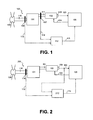
- a rotor 109 and a generator 102 of a wind turbine 100, 200 which are mechanically connected to each other by a drive train consisting of a rotor output shaft 110, a gear 101, a shaft 111 with coupling.
- the rotor is mounted on a rotor-side end of the drive train, the generator on a generator-side end.
- the generator 102 is equipped with a rotational speed sensor 108 (rotary encoder) which detects the generator rotational speed 103 and transmits it to a computing unit 105, which is set up for the control of the wind energy plant and is therefore referred to as "plant control".
- the system controller 105 is set up to influence the power decrease of the generator 102 via actuating signals 104, which in particular drive a power converter and / or a rotor of the generator accordingly.
- a second sensor 107 On the input side of the transmission, a first sensor 106 and the output side, a second sensor 107 is arranged, each of which detect a measurement signal 113, 114 (in particular a series of measured values) and transmitted to a damping control 112, in which an operation 115 for the generator 102 and determines the system controller 105 is transmitted.
- an additive actuating torque 115 for the generator is calculated from the detected measuring signals 113 and 114 in the damping controller 112 as an intervention and transmitted to the system controller 105.
- This superimposes a set load torque of the generator with the additive setting torque.
- the desired load torque of the generator can originate, for example, from a power and / or speed control, which can be implemented in wind turbines.
- the damping control 112 may be implemented as part of the plant controller 105 in one embodiment.
- the measurement signals 113 and 114 are preferably speed signals, but may also be acceleration signals or torsional moment signals.
- the damping controller 112 is configured to determine, taking into account a gear ratio of the transmission 101, a rotational speed difference between the rotational speed 113 of the rotor output shaft 110 as the input shaft of the transmission 101 and the rotational speed 114 of the shaft 111 as the output shaft of the transmission 101. "Taking into account one
- the damping controller 112 is further configured to control this speed difference to a setpoint that is preferably zero, namely, it can be assumed that torsional vibrations through the transmission are minimal, if no speed deviation In this way, torsional vibration may be damped via a powertrain component, such as the transmission 12.
- the design of the damping controller preferably takes place according to the approach for non-collocated systems and has, for example, a model-based controller Also, a measured torsional moment difference or a single measured torsional moment can be controlled to zero.
- FIG. 2 a wind turbine 200 is shown in which no sensor is present on the shaft 111. Instead, the generator speed 103 is supplied to the damping controller 212.
- the damping controller 212 is now set up to determine a speed difference between the rotational speed 113 of the rotor output shaft 110 as the input shaft of the transmission 101 and the rotational speed 103 of the generator 102, so to speak as the output shaft of the transmission 101, taking into account the transmission ratios involved.
- the damping controller 212 is further configured to control this speed difference to a setpoint, which is preferably zero. It can be assumed that torsional vibrations between the transmission input shaft and the generator shaft are minimal if there is no speed deviation. In this way, a torsional vibration via a drive train component, as here the transmission together with the generator shaft, are damped.
- the design of the damping controller in this case is preferably in accordance with the approach for collocated systems and has, for example, a P-controller.
Landscapes
- Engineering & Computer Science (AREA)
- General Engineering & Computer Science (AREA)
- Mechanical Engineering (AREA)
- Chemical & Material Sciences (AREA)
- Combustion & Propulsion (AREA)
- Life Sciences & Earth Sciences (AREA)
- Sustainable Development (AREA)
- Sustainable Energy (AREA)
- Physics & Mathematics (AREA)
- General Physics & Mathematics (AREA)
- Power Engineering (AREA)
- Automation & Control Theory (AREA)
- Aviation & Aerospace Engineering (AREA)
- Acoustics & Sound (AREA)
- Wind Motors (AREA)
- Hydraulic Clutches, Magnetic Clutches, Fluid Clutches, And Fluid Joints (AREA)
- Control Of Eletrric Generators (AREA)
Applications Claiming Priority (1)
| Application Number | Priority Date | Filing Date | Title |
|---|---|---|---|
| DE102012010420A DE102012010420A1 (de) | 2012-05-29 | 2012-05-29 | Verfahren zur Dämpfung von Torsionsschwingungenin einer Antriebsstrangkomponente |
Publications (3)
| Publication Number | Publication Date |
|---|---|
| EP2669513A2 true EP2669513A2 (fr) | 2013-12-04 |
| EP2669513A3 EP2669513A3 (fr) | 2015-01-21 |
| EP2669513B1 EP2669513B1 (fr) | 2018-06-20 |
Family
ID=48236633
Family Applications (1)
| Application Number | Title | Priority Date | Filing Date |
|---|---|---|---|
| EP13002169.4A Not-in-force EP2669513B1 (fr) | 2012-05-29 | 2013-05-03 | Procédé d'amortissement des oscillations de torsion dans un composant d'une transmission |
Country Status (7)
| Country | Link |
|---|---|
| US (1) | US8860382B2 (fr) |
| EP (1) | EP2669513B1 (fr) |
| KR (1) | KR20130133679A (fr) |
| CN (1) | CN103452773B (fr) |
| DE (1) | DE102012010420A1 (fr) |
| DK (1) | DK2669513T3 (fr) |
| ES (1) | ES2685334T3 (fr) |
Cited By (2)
| Publication number | Priority date | Publication date | Assignee | Title |
|---|---|---|---|---|
| WO2016000733A1 (fr) * | 2014-07-04 | 2016-01-07 | Volvo Truck Corporation | Procédé de détection de performances d'amortissement d'un amortisseur de torsion |
| CN106089581A (zh) * | 2015-03-13 | 2016-11-09 | 通用电气公司 | 用于风轮机的可变末梢速度比控制的系统及方法 |
Families Citing this family (8)
| Publication number | Priority date | Publication date | Assignee | Title |
|---|---|---|---|---|
| DK2365215T3 (da) * | 2010-03-10 | 2013-01-28 | Siemens Ag | Styring af rotationshastigheden af en vindmølle baseret på rotoracceleration |
| GB201320191D0 (en) * | 2013-11-15 | 2014-01-01 | Ricardo Uk Ltd | Wind turbine |
| EP2990609A1 (fr) * | 2014-09-01 | 2016-03-02 | Siemens Aktiengesellschaft | Procédé de fonctionnement d'une installation de machine dotée d'une ligne d'arbres |
| CN104329220B (zh) * | 2014-09-03 | 2017-04-12 | 上海交通大学 | 用于抑制风电机组扭振的扭转载荷控制器及控制方法 |
| GB201501135D0 (en) * | 2015-01-23 | 2015-03-11 | Rolls Royce Plc | Method and system for damping torsional oscillations |
| US10415544B2 (en) * | 2017-01-03 | 2019-09-17 | General Electric Company | System and method for determining torque on a wind turbine shaft |
| US11014550B2 (en) | 2019-02-07 | 2021-05-25 | Fca Us Llc | Disturbance mitigation techniques for hybrid power-split transmissions |
| CN115217714B (zh) * | 2022-02-22 | 2024-07-19 | 上海电力大学 | 一种基于转动惯量虚拟配置的风电轴系降载控制策略 |
Citations (3)
| Publication number | Priority date | Publication date | Assignee | Title |
|---|---|---|---|---|
| US20080067815A1 (en) | 2004-09-30 | 2008-03-20 | General Electric Company | Vibration damping method for variable speed wind turbines |
| DE102007019907B4 (de) | 2007-04-27 | 2009-04-30 | Nordex Energy Gmbh | Vorrichtung zur aktiven Dämpfung eines Triebstrangs bei einer Windenergieanlage |
| DE102009059669A1 (de) | 2009-12-19 | 2011-06-22 | Robert Bosch GmbH, 70469 | Verfahren und Vorrichtung zur Dämpfung von Torsionsschwingungen |
Family Cites Families (10)
| Publication number | Priority date | Publication date | Assignee | Title |
|---|---|---|---|---|
| US4695736A (en) * | 1985-11-18 | 1987-09-22 | United Technologies Corporation | Variable speed wind turbine |
| US7518344B2 (en) * | 2003-06-13 | 2009-04-14 | MAX-PLANCK-Gesellschaft zur Förderung der Wissenschaften e.V. | Method and damping device for damping a torsional vibration in a rotating drivetrain |
| EP1719910B1 (fr) * | 2004-02-27 | 2019-06-26 | Mitsubishi Heavy Industries, Ltd. | Aérogénérateur, son procédé d'amortissement actif des vibrations et tour de turbine éolienne |
| WO2008028436A1 (fr) * | 2006-09-07 | 2008-03-13 | Siemens Aktiengesellschaft | Dispositif de régulation de l'amortissement |
| US7808215B2 (en) * | 2007-07-02 | 2010-10-05 | Hamilton Sundstrand Corporation | Active damping for synchronous generator torsional oscillations |
| ATE552421T1 (de) * | 2008-05-14 | 2012-04-15 | Alstom Wind Sl | Verfahren zur reduktion von torsionsschwingungen im antriebsstrang einer windturbine |
| DE102008043103A1 (de) * | 2008-10-22 | 2010-04-29 | Alstrom Technology Ltd. | Vorrichtung und Verfahren zur Überwachung und/oder Analyse von Rotoren von elektrischen Maschinen im Betrieb |
| US8217630B2 (en) * | 2009-11-18 | 2012-07-10 | Hamilton Sundstrand Corporation | Electric load damper for damping torsional oscillation |
| US7939956B1 (en) * | 2010-04-09 | 2011-05-10 | General Electric Company | Torsional protection system and method for wind turbine |
| EP2479427A1 (fr) * | 2011-01-24 | 2012-07-25 | Siemens Aktiengesellschaft | Procédé d'amortissement d'oscillations d'un entraînement dans une éolienne, éolienne et utilisation d'un dispositif de freinage |
-
2012
- 2012-05-29 DE DE102012010420A patent/DE102012010420A1/de not_active Withdrawn
-
2013
- 2013-05-03 ES ES13002169.4T patent/ES2685334T3/es active Active
- 2013-05-03 DK DK13002169.4T patent/DK2669513T3/en active
- 2013-05-03 EP EP13002169.4A patent/EP2669513B1/fr not_active Not-in-force
- 2013-05-28 KR KR1020130060176A patent/KR20130133679A/ko not_active Application Discontinuation
- 2013-05-28 US US13/903,616 patent/US8860382B2/en not_active Expired - Fee Related
- 2013-05-28 CN CN201310203271.2A patent/CN103452773B/zh not_active Expired - Fee Related
Patent Citations (3)
| Publication number | Priority date | Publication date | Assignee | Title |
|---|---|---|---|---|
| US20080067815A1 (en) | 2004-09-30 | 2008-03-20 | General Electric Company | Vibration damping method for variable speed wind turbines |
| DE102007019907B4 (de) | 2007-04-27 | 2009-04-30 | Nordex Energy Gmbh | Vorrichtung zur aktiven Dämpfung eines Triebstrangs bei einer Windenergieanlage |
| DE102009059669A1 (de) | 2009-12-19 | 2011-06-22 | Robert Bosch GmbH, 70469 | Verfahren und Vorrichtung zur Dämpfung von Torsionsschwingungen |
Cited By (4)
| Publication number | Priority date | Publication date | Assignee | Title |
|---|---|---|---|---|
| WO2016000733A1 (fr) * | 2014-07-04 | 2016-01-07 | Volvo Truck Corporation | Procédé de détection de performances d'amortissement d'un amortisseur de torsion |
| CN106089581A (zh) * | 2015-03-13 | 2016-11-09 | 通用电气公司 | 用于风轮机的可变末梢速度比控制的系统及方法 |
| US10473088B2 (en) | 2015-03-13 | 2019-11-12 | General Electric Company | System and method for variable tip-speed-ratio control of a wind turbine |
| CN106089581B (zh) * | 2015-03-13 | 2020-02-07 | 通用电气公司 | 用于风轮机的可变末梢速度比控制的系统及方法 |
Also Published As
| Publication number | Publication date |
|---|---|
| ES2685334T3 (es) | 2018-10-08 |
| CN103452773B (zh) | 2019-05-14 |
| EP2669513A3 (fr) | 2015-01-21 |
| DK2669513T3 (en) | 2018-10-01 |
| EP2669513B1 (fr) | 2018-06-20 |
| KR20130133679A (ko) | 2013-12-09 |
| US8860382B2 (en) | 2014-10-14 |
| US20130320935A1 (en) | 2013-12-05 |
| DE102012010420A1 (de) | 2013-12-05 |
| CN103452773A (zh) | 2013-12-18 |
Similar Documents
| Publication | Publication Date | Title |
|---|---|---|
| EP2669513B1 (fr) | Procédé d'amortissement des oscillations de torsion dans un composant d'une transmission | |
| EP2513656B1 (fr) | Procédé et dispositif d'amortissement des vibrations de torsion | |
| EP3133282B1 (fr) | Procede et systeme de surveillance d'un dispositif de reglage de pale individuelle d'une eolienne | |
| DE102006029640B4 (de) | Windenergieanlage mit einem Maschinenhaus | |
| EP2887023A2 (fr) | Procédé de détermination d'une position d'angle de rotation et/ou d'une vitesse de rotation | |
| EP3420226B1 (fr) | Procédé pour déterminer une vitesse du vent équivalente | |
| DE102010009863A1 (de) | Einrichtung und Verfahren zur Reduzierung von Lasten | |
| DE3308564A1 (de) | Windturbinenanlage | |
| EP2479427A1 (fr) | Procédé d'amortissement d'oscillations d'un entraînement dans une éolienne, éolienne et utilisation d'un dispositif de freinage | |
| DE3308566A1 (de) | Windturbinenanlage | |
| DE102007030268B4 (de) | Verfahren und Vorrichtung zur indirekten Bestimmung dynamischer Größen einer Wind- oder Wasserkraftanlage mittels beliebig angeordneter Messsensoren | |
| EP1290343A1 (fr) | Organe d'entrainement azimutal pour eoliennes | |
| EP2622214A1 (fr) | Procédé pour l'adaptation de la vitesse de rotation d'une installation d'énergie éolienne et installation d'énergie éolienne | |
| WO2013072005A1 (fr) | Procédé d'amortissement d'oscillations de torsion dans une installation de production d'énergie | |
| DE102016007098A1 (de) | Windpark mit schneller Reaktion auf Netzparameteränderungen und Verfahren hierfür | |
| DE102007040834A1 (de) | Verfahren zum Betreiben einer Windenergieanlage und Steuer- und Regeleinheit zur Ausführung des Verfahrens | |
| DE102007058054A1 (de) | Verfahren zur Regelung der elektrischen Last einer Windenergieanlage | |
| DE102013201162A1 (de) | Verfahren zur Azimutverstellung einer Windenergieanlage, Azimutverstellsystem und Windenergieanlage | |
| EP2215355A2 (fr) | Procédé de régulation de la charge électrique d'une éolienne | |
| DE102015004393A1 (de) | Windenergieanlage und Verfahren zum Betreiben einer Windenergieanlage | |
| EP3495656B1 (fr) | Procédé de détermination de la dynamique de charge d'une éolienne | |
| DE102009052240A1 (de) | Windkraftanlage | |
| DE10023440C1 (de) | Azimutantrieb für Windenergieanlagen | |
| DE102013204492A1 (de) | Verfahren und System zur Überwachung einer Einzelblattverstellung einer Windenergieanlage | |
| WO2024061598A1 (fr) | Chaîne cinématique pour éolienne et série de chaînes cinématiques |
Legal Events
| Date | Code | Title | Description |
|---|---|---|---|
| PUAI | Public reference made under article 153(3) epc to a published international application that has entered the european phase |
Free format text: ORIGINAL CODE: 0009012 |
|
| AK | Designated contracting states |
Kind code of ref document: A2 Designated state(s): AL AT BE BG CH CY CZ DE DK EE ES FI FR GB GR HR HU IE IS IT LI LT LU LV MC MK MT NL NO PL PT RO RS SE SI SK SM TR |
|
| AX | Request for extension of the european patent |
Extension state: BA ME |
|
| PUAL | Search report despatched |
Free format text: ORIGINAL CODE: 0009013 |
|
| AK | Designated contracting states |
Kind code of ref document: A3 Designated state(s): AL AT BE BG CH CY CZ DE DK EE ES FI FR GB GR HR HU IE IS IT LI LT LU LV MC MK MT NL NO PL PT RO RS SE SI SK SM TR |
|
| AX | Request for extension of the european patent |
Extension state: BA ME |
|
| RIC1 | Information provided on ipc code assigned before grant |
Ipc: F03D 7/02 20060101ALI20141216BHEP Ipc: F03D 11/02 20060101AFI20141216BHEP |
|
| 17P | Request for examination filed |
Effective date: 20150721 |
|
| RBV | Designated contracting states (corrected) |
Designated state(s): AL AT BE BG CH CY CZ DE DK EE ES FI FR GB GR HR HU IE IS IT LI LT LU LV MC MK MT NL NO PL PT RO RS SE SI SK SM TR |
|
| RAP1 | Party data changed (applicant data changed or rights of an application transferred) |
Owner name: ZF FRIEDRICHSHAFEN AG |
|
| REG | Reference to a national code |
Ref country code: DE Ref legal event code: R079 Ref document number: 502013010409 Country of ref document: DE Free format text: PREVIOUS MAIN CLASS: F03D0011020000 Ipc: F03D0007020000 |
|
| RIC1 | Information provided on ipc code assigned before grant |
Ipc: F03D 7/02 20060101AFI20171124BHEP |
|
| GRAP | Despatch of communication of intention to grant a patent |
Free format text: ORIGINAL CODE: EPIDOSNIGR1 |
|
| STAA | Information on the status of an ep patent application or granted ep patent |
Free format text: STATUS: GRANT OF PATENT IS INTENDED |
|
| INTG | Intention to grant announced |
Effective date: 20180119 |
|
| INTG | Intention to grant announced |
Effective date: 20180126 |
|
| GRAS | Grant fee paid |
Free format text: ORIGINAL CODE: EPIDOSNIGR3 |
|
| GRAA | (expected) grant |
Free format text: ORIGINAL CODE: 0009210 |
|
| STAA | Information on the status of an ep patent application or granted ep patent |
Free format text: STATUS: THE PATENT HAS BEEN GRANTED |
|
| AK | Designated contracting states |
Kind code of ref document: B1 Designated state(s): AL AT BE BG CH CY CZ DE DK EE ES FI FR GB GR HR HU IE IS IT LI LT LU LV MC MK MT NL NO PL PT RO RS SE SI SK SM TR |
|
| REG | Reference to a national code |
Ref country code: GB Ref legal event code: FG4D Free format text: NOT ENGLISH |
|
| REG | Reference to a national code |
Ref country code: IE Ref legal event code: FG4D Free format text: LANGUAGE OF EP DOCUMENT: GERMAN |
|
| REG | Reference to a national code |
Ref country code: AT Ref legal event code: REF Ref document number: 1010781 Country of ref document: AT Kind code of ref document: T Effective date: 20180715 |
|
| REG | Reference to a national code |
Ref country code: DE Ref legal event code: R096 Ref document number: 502013010409 Country of ref document: DE |
|
| REG | Reference to a national code |
Ref country code: DK Ref legal event code: T3 Effective date: 20180926 |
|
| REG | Reference to a national code |
Ref country code: ES Ref legal event code: FG2A Ref document number: 2685334 Country of ref document: ES Kind code of ref document: T3 Effective date: 20181008 |
|
| REG | Reference to a national code |
Ref country code: NL Ref legal event code: MP Effective date: 20180620 |
|
| PG25 | Lapsed in a contracting state [announced via postgrant information from national office to epo] |
Ref country code: LT Free format text: LAPSE BECAUSE OF FAILURE TO SUBMIT A TRANSLATION OF THE DESCRIPTION OR TO PAY THE FEE WITHIN THE PRESCRIBED TIME-LIMIT Effective date: 20180620 Ref country code: BG Free format text: LAPSE BECAUSE OF FAILURE TO SUBMIT A TRANSLATION OF THE DESCRIPTION OR TO PAY THE FEE WITHIN THE PRESCRIBED TIME-LIMIT Effective date: 20180920 Ref country code: NO Free format text: LAPSE BECAUSE OF FAILURE TO SUBMIT A TRANSLATION OF THE DESCRIPTION OR TO PAY THE FEE WITHIN THE PRESCRIBED TIME-LIMIT Effective date: 20180920 Ref country code: SE Free format text: LAPSE BECAUSE OF FAILURE TO SUBMIT A TRANSLATION OF THE DESCRIPTION OR TO PAY THE FEE WITHIN THE PRESCRIBED TIME-LIMIT Effective date: 20180620 |
|
| REG | Reference to a national code |
Ref country code: LT Ref legal event code: MG4D |
|
| PG25 | Lapsed in a contracting state [announced via postgrant information from national office to epo] |
Ref country code: LV Free format text: LAPSE BECAUSE OF FAILURE TO SUBMIT A TRANSLATION OF THE DESCRIPTION OR TO PAY THE FEE WITHIN THE PRESCRIBED TIME-LIMIT Effective date: 20180620 Ref country code: HR Free format text: LAPSE BECAUSE OF FAILURE TO SUBMIT A TRANSLATION OF THE DESCRIPTION OR TO PAY THE FEE WITHIN THE PRESCRIBED TIME-LIMIT Effective date: 20180620 Ref country code: GR Free format text: LAPSE BECAUSE OF FAILURE TO SUBMIT A TRANSLATION OF THE DESCRIPTION OR TO PAY THE FEE WITHIN THE PRESCRIBED TIME-LIMIT Effective date: 20180921 Ref country code: RS Free format text: LAPSE BECAUSE OF FAILURE TO SUBMIT A TRANSLATION OF THE DESCRIPTION OR TO PAY THE FEE WITHIN THE PRESCRIBED TIME-LIMIT Effective date: 20180620 |
|
| PG25 | Lapsed in a contracting state [announced via postgrant information from national office to epo] |
Ref country code: NL Free format text: LAPSE BECAUSE OF FAILURE TO SUBMIT A TRANSLATION OF THE DESCRIPTION OR TO PAY THE FEE WITHIN THE PRESCRIBED TIME-LIMIT Effective date: 20180620 |
|
| PG25 | Lapsed in a contracting state [announced via postgrant information from national office to epo] |
Ref country code: PL Free format text: LAPSE BECAUSE OF FAILURE TO SUBMIT A TRANSLATION OF THE DESCRIPTION OR TO PAY THE FEE WITHIN THE PRESCRIBED TIME-LIMIT Effective date: 20180620 Ref country code: CZ Free format text: LAPSE BECAUSE OF FAILURE TO SUBMIT A TRANSLATION OF THE DESCRIPTION OR TO PAY THE FEE WITHIN THE PRESCRIBED TIME-LIMIT Effective date: 20180620 Ref country code: SK Free format text: LAPSE BECAUSE OF FAILURE TO SUBMIT A TRANSLATION OF THE DESCRIPTION OR TO PAY THE FEE WITHIN THE PRESCRIBED TIME-LIMIT Effective date: 20180620 Ref country code: RO Free format text: LAPSE BECAUSE OF FAILURE TO SUBMIT A TRANSLATION OF THE DESCRIPTION OR TO PAY THE FEE WITHIN THE PRESCRIBED TIME-LIMIT Effective date: 20180620 Ref country code: EE Free format text: LAPSE BECAUSE OF FAILURE TO SUBMIT A TRANSLATION OF THE DESCRIPTION OR TO PAY THE FEE WITHIN THE PRESCRIBED TIME-LIMIT Effective date: 20180620 Ref country code: IS Free format text: LAPSE BECAUSE OF FAILURE TO SUBMIT A TRANSLATION OF THE DESCRIPTION OR TO PAY THE FEE WITHIN THE PRESCRIBED TIME-LIMIT Effective date: 20181020 |
|
| PG25 | Lapsed in a contracting state [announced via postgrant information from national office to epo] |
Ref country code: SM Free format text: LAPSE BECAUSE OF FAILURE TO SUBMIT A TRANSLATION OF THE DESCRIPTION OR TO PAY THE FEE WITHIN THE PRESCRIBED TIME-LIMIT Effective date: 20180620 Ref country code: IT Free format text: LAPSE BECAUSE OF FAILURE TO SUBMIT A TRANSLATION OF THE DESCRIPTION OR TO PAY THE FEE WITHIN THE PRESCRIBED TIME-LIMIT Effective date: 20180620 |
|
| REG | Reference to a national code |
Ref country code: DE Ref legal event code: R097 Ref document number: 502013010409 Country of ref document: DE |
|
| PLBE | No opposition filed within time limit |
Free format text: ORIGINAL CODE: 0009261 |
|
| STAA | Information on the status of an ep patent application or granted ep patent |
Free format text: STATUS: NO OPPOSITION FILED WITHIN TIME LIMIT |
|
| 26N | No opposition filed |
Effective date: 20190321 |
|
| PG25 | Lapsed in a contracting state [announced via postgrant information from national office to epo] |
Ref country code: SI Free format text: LAPSE BECAUSE OF FAILURE TO SUBMIT A TRANSLATION OF THE DESCRIPTION OR TO PAY THE FEE WITHIN THE PRESCRIBED TIME-LIMIT Effective date: 20180620 |
|
| PG25 | Lapsed in a contracting state [announced via postgrant information from national office to epo] |
Ref country code: AL Free format text: LAPSE BECAUSE OF FAILURE TO SUBMIT A TRANSLATION OF THE DESCRIPTION OR TO PAY THE FEE WITHIN THE PRESCRIBED TIME-LIMIT Effective date: 20180620 |
|
| REG | Reference to a national code |
Ref country code: CH Ref legal event code: PL |
|
| GBPC | Gb: european patent ceased through non-payment of renewal fee |
Effective date: 20190503 |
|
| PG25 | Lapsed in a contracting state [announced via postgrant information from national office to epo] |
Ref country code: LI Free format text: LAPSE BECAUSE OF NON-PAYMENT OF DUE FEES Effective date: 20190531 Ref country code: CH Free format text: LAPSE BECAUSE OF NON-PAYMENT OF DUE FEES Effective date: 20190531 Ref country code: MC Free format text: LAPSE BECAUSE OF FAILURE TO SUBMIT A TRANSLATION OF THE DESCRIPTION OR TO PAY THE FEE WITHIN THE PRESCRIBED TIME-LIMIT Effective date: 20180620 |
|
| REG | Reference to a national code |
Ref country code: BE Ref legal event code: MM Effective date: 20190531 |
|
| PG25 | Lapsed in a contracting state [announced via postgrant information from national office to epo] |
Ref country code: LU Free format text: LAPSE BECAUSE OF NON-PAYMENT OF DUE FEES Effective date: 20190503 |
|
| PG25 | Lapsed in a contracting state [announced via postgrant information from national office to epo] |
Ref country code: TR Free format text: LAPSE BECAUSE OF FAILURE TO SUBMIT A TRANSLATION OF THE DESCRIPTION OR TO PAY THE FEE WITHIN THE PRESCRIBED TIME-LIMIT Effective date: 20180620 |
|
| PG25 | Lapsed in a contracting state [announced via postgrant information from national office to epo] |
Ref country code: GB Free format text: LAPSE BECAUSE OF NON-PAYMENT OF DUE FEES Effective date: 20190503 Ref country code: IE Free format text: LAPSE BECAUSE OF NON-PAYMENT OF DUE FEES Effective date: 20190503 |
|
| PG25 | Lapsed in a contracting state [announced via postgrant information from national office to epo] |
Ref country code: BE Free format text: LAPSE BECAUSE OF NON-PAYMENT OF DUE FEES Effective date: 20190531 |
|
| PG25 | Lapsed in a contracting state [announced via postgrant information from national office to epo] |
Ref country code: FR Free format text: LAPSE BECAUSE OF NON-PAYMENT OF DUE FEES Effective date: 20190531 Ref country code: PT Free format text: LAPSE BECAUSE OF FAILURE TO SUBMIT A TRANSLATION OF THE DESCRIPTION OR TO PAY THE FEE WITHIN THE PRESCRIBED TIME-LIMIT Effective date: 20181022 |
|
| PGFP | Annual fee paid to national office [announced via postgrant information from national office to epo] |
Ref country code: DK Payment date: 20200512 Year of fee payment: 8 Ref country code: FI Payment date: 20200511 Year of fee payment: 8 Ref country code: DE Payment date: 20200422 Year of fee payment: 8 Ref country code: ES Payment date: 20200601 Year of fee payment: 8 |
|
| REG | Reference to a national code |
Ref country code: AT Ref legal event code: MM01 Ref document number: 1010781 Country of ref document: AT Kind code of ref document: T Effective date: 20190503 |
|
| PG25 | Lapsed in a contracting state [announced via postgrant information from national office to epo] |
Ref country code: AT Free format text: LAPSE BECAUSE OF NON-PAYMENT OF DUE FEES Effective date: 20190503 |
|
| PG25 | Lapsed in a contracting state [announced via postgrant information from national office to epo] |
Ref country code: CY Free format text: LAPSE BECAUSE OF FAILURE TO SUBMIT A TRANSLATION OF THE DESCRIPTION OR TO PAY THE FEE WITHIN THE PRESCRIBED TIME-LIMIT Effective date: 20180620 |
|
| PG25 | Lapsed in a contracting state [announced via postgrant information from national office to epo] |
Ref country code: HU Free format text: LAPSE BECAUSE OF FAILURE TO SUBMIT A TRANSLATION OF THE DESCRIPTION OR TO PAY THE FEE WITHIN THE PRESCRIBED TIME-LIMIT; INVALID AB INITIO Effective date: 20130503 Ref country code: MT Free format text: LAPSE BECAUSE OF FAILURE TO SUBMIT A TRANSLATION OF THE DESCRIPTION OR TO PAY THE FEE WITHIN THE PRESCRIBED TIME-LIMIT Effective date: 20180620 |
|
| REG | Reference to a national code |
Ref country code: DE Ref legal event code: R119 Ref document number: 502013010409 Country of ref document: DE |
|
| REG | Reference to a national code |
Ref country code: FI Ref legal event code: MAE |
|
| REG | Reference to a national code |
Ref country code: DK Ref legal event code: EBP Effective date: 20210531 |
|
| PG25 | Lapsed in a contracting state [announced via postgrant information from national office to epo] |
Ref country code: FI Free format text: LAPSE BECAUSE OF NON-PAYMENT OF DUE FEES Effective date: 20210503 |
|
| PG25 | Lapsed in a contracting state [announced via postgrant information from national office to epo] |
Ref country code: DK Free format text: LAPSE BECAUSE OF NON-PAYMENT OF DUE FEES Effective date: 20210531 Ref country code: DE Free format text: LAPSE BECAUSE OF NON-PAYMENT OF DUE FEES Effective date: 20211201 |
|
| PG25 | Lapsed in a contracting state [announced via postgrant information from national office to epo] |
Ref country code: MK Free format text: LAPSE BECAUSE OF FAILURE TO SUBMIT A TRANSLATION OF THE DESCRIPTION OR TO PAY THE FEE WITHIN THE PRESCRIBED TIME-LIMIT Effective date: 20180620 |
|
| REG | Reference to a national code |
Ref country code: ES Ref legal event code: FD2A Effective date: 20220802 |
|
| PG25 | Lapsed in a contracting state [announced via postgrant information from national office to epo] |
Ref country code: ES Free format text: LAPSE BECAUSE OF NON-PAYMENT OF DUE FEES Effective date: 20210504 |