EP2669499A1 - Cogeneration system - Google Patents
Cogeneration system Download PDFInfo
- Publication number
- EP2669499A1 EP2669499A1 EP12738955.9A EP12738955A EP2669499A1 EP 2669499 A1 EP2669499 A1 EP 2669499A1 EP 12738955 A EP12738955 A EP 12738955A EP 2669499 A1 EP2669499 A1 EP 2669499A1
- Authority
- EP
- European Patent Office
- Prior art keywords
- heat
- electricity
- pump
- driven
- thermally
- Prior art date
- Legal status (The legal status is an assumption and is not a legal conclusion. Google has not performed a legal analysis and makes no representation as to the accuracy of the status listed.)
- Withdrawn
Links
Images


Classifications
-
- F—MECHANICAL ENGINEERING; LIGHTING; HEATING; WEAPONS; BLASTING
- F01—MACHINES OR ENGINES IN GENERAL; ENGINE PLANTS IN GENERAL; STEAM ENGINES
- F01K—STEAM ENGINE PLANTS; STEAM ACCUMULATORS; ENGINE PLANTS NOT OTHERWISE PROVIDED FOR; ENGINES USING SPECIAL WORKING FLUIDS OR CYCLES
- F01K13/00—General layout or general methods of operation of complete plants
- F01K13/02—Controlling, e.g. stopping or starting
-
- F—MECHANICAL ENGINEERING; LIGHTING; HEATING; WEAPONS; BLASTING
- F25—REFRIGERATION OR COOLING; COMBINED HEATING AND REFRIGERATION SYSTEMS; HEAT PUMP SYSTEMS; MANUFACTURE OR STORAGE OF ICE; LIQUEFACTION SOLIDIFICATION OF GASES
- F25B—REFRIGERATION MACHINES, PLANTS OR SYSTEMS; COMBINED HEATING AND REFRIGERATION SYSTEMS; HEAT PUMP SYSTEMS
- F25B30/00—Heat pumps
- F25B30/02—Heat pumps of the compression type
-
- F—MECHANICAL ENGINEERING; LIGHTING; HEATING; WEAPONS; BLASTING
- F02—COMBUSTION ENGINES; HOT-GAS OR COMBUSTION-PRODUCT ENGINE PLANTS
- F02G—HOT GAS OR COMBUSTION-PRODUCT POSITIVE-DISPLACEMENT ENGINE PLANTS; USE OF WASTE HEAT OF COMBUSTION ENGINES; NOT OTHERWISE PROVIDED FOR
- F02G5/00—Profiting from waste heat of combustion engines, not otherwise provided for
- F02G5/02—Profiting from waste heat of exhaust gases
- F02G5/04—Profiting from waste heat of exhaust gases in combination with other waste heat from combustion engines
-
- F—MECHANICAL ENGINEERING; LIGHTING; HEATING; WEAPONS; BLASTING
- F25—REFRIGERATION OR COOLING; COMBINED HEATING AND REFRIGERATION SYSTEMS; HEAT PUMP SYSTEMS; MANUFACTURE OR STORAGE OF ICE; LIQUEFACTION SOLIDIFICATION OF GASES
- F25B—REFRIGERATION MACHINES, PLANTS OR SYSTEMS; COMBINED HEATING AND REFRIGERATION SYSTEMS; HEAT PUMP SYSTEMS
- F25B15/00—Sorption machines, plants or systems, operating continuously, e.g. absorption type
-
- F—MECHANICAL ENGINEERING; LIGHTING; HEATING; WEAPONS; BLASTING
- F25—REFRIGERATION OR COOLING; COMBINED HEATING AND REFRIGERATION SYSTEMS; HEAT PUMP SYSTEMS; MANUFACTURE OR STORAGE OF ICE; LIQUEFACTION SOLIDIFICATION OF GASES
- F25B—REFRIGERATION MACHINES, PLANTS OR SYSTEMS; COMBINED HEATING AND REFRIGERATION SYSTEMS; HEAT PUMP SYSTEMS
- F25B25/00—Machines, plants or systems, using a combination of modes of operation covered by two or more of the groups F25B1/00 - F25B23/00
- F25B25/02—Compression-sorption machines, plants, or systems
-
- F—MECHANICAL ENGINEERING; LIGHTING; HEATING; WEAPONS; BLASTING
- F25—REFRIGERATION OR COOLING; COMBINED HEATING AND REFRIGERATION SYSTEMS; HEAT PUMP SYSTEMS; MANUFACTURE OR STORAGE OF ICE; LIQUEFACTION SOLIDIFICATION OF GASES
- F25B—REFRIGERATION MACHINES, PLANTS OR SYSTEMS; COMBINED HEATING AND REFRIGERATION SYSTEMS; HEAT PUMP SYSTEMS
- F25B27/00—Machines, plants or systems, using particular sources of energy
- F25B27/02—Machines, plants or systems, using particular sources of energy using waste heat, e.g. from internal-combustion engines
-
- Y—GENERAL TAGGING OF NEW TECHNOLOGICAL DEVELOPMENTS; GENERAL TAGGING OF CROSS-SECTIONAL TECHNOLOGIES SPANNING OVER SEVERAL SECTIONS OF THE IPC; TECHNICAL SUBJECTS COVERED BY FORMER USPC CROSS-REFERENCE ART COLLECTIONS [XRACs] AND DIGESTS
- Y02—TECHNOLOGIES OR APPLICATIONS FOR MITIGATION OR ADAPTATION AGAINST CLIMATE CHANGE
- Y02A—TECHNOLOGIES FOR ADAPTATION TO CLIMATE CHANGE
- Y02A30/00—Adapting or protecting infrastructure or their operation
- Y02A30/27—Relating to heating, ventilation or air conditioning [HVAC] technologies
- Y02A30/274—Relating to heating, ventilation or air conditioning [HVAC] technologies using waste energy, e.g. from internal combustion engine
-
- Y—GENERAL TAGGING OF NEW TECHNOLOGICAL DEVELOPMENTS; GENERAL TAGGING OF CROSS-SECTIONAL TECHNOLOGIES SPANNING OVER SEVERAL SECTIONS OF THE IPC; TECHNICAL SUBJECTS COVERED BY FORMER USPC CROSS-REFERENCE ART COLLECTIONS [XRACs] AND DIGESTS
- Y02—TECHNOLOGIES OR APPLICATIONS FOR MITIGATION OR ADAPTATION AGAINST CLIMATE CHANGE
- Y02B—CLIMATE CHANGE MITIGATION TECHNOLOGIES RELATED TO BUILDINGS, e.g. HOUSING, HOUSE APPLIANCES OR RELATED END-USER APPLICATIONS
- Y02B30/00—Energy efficient heating, ventilation or air conditioning [HVAC]
- Y02B30/52—Heat recovery pumps, i.e. heat pump based systems or units able to transfer the thermal energy from one area of the premises or part of the facilities to a different one, improving the overall efficiency
-
- Y—GENERAL TAGGING OF NEW TECHNOLOGICAL DEVELOPMENTS; GENERAL TAGGING OF CROSS-SECTIONAL TECHNOLOGIES SPANNING OVER SEVERAL SECTIONS OF THE IPC; TECHNICAL SUBJECTS COVERED BY FORMER USPC CROSS-REFERENCE ART COLLECTIONS [XRACs] AND DIGESTS
- Y02—TECHNOLOGIES OR APPLICATIONS FOR MITIGATION OR ADAPTATION AGAINST CLIMATE CHANGE
- Y02B—CLIMATE CHANGE MITIGATION TECHNOLOGIES RELATED TO BUILDINGS, e.g. HOUSING, HOUSE APPLIANCES OR RELATED END-USER APPLICATIONS
- Y02B30/00—Energy efficient heating, ventilation or air conditioning [HVAC]
- Y02B30/62—Absorption based systems
- Y02B30/625—Absorption based systems combined with heat or power generation [CHP], e.g. trigeneration
-
- Y—GENERAL TAGGING OF NEW TECHNOLOGICAL DEVELOPMENTS; GENERAL TAGGING OF CROSS-SECTIONAL TECHNOLOGIES SPANNING OVER SEVERAL SECTIONS OF THE IPC; TECHNICAL SUBJECTS COVERED BY FORMER USPC CROSS-REFERENCE ART COLLECTIONS [XRACs] AND DIGESTS
- Y02—TECHNOLOGIES OR APPLICATIONS FOR MITIGATION OR ADAPTATION AGAINST CLIMATE CHANGE
- Y02E—REDUCTION OF GREENHOUSE GAS [GHG] EMISSIONS, RELATED TO ENERGY GENERATION, TRANSMISSION OR DISTRIBUTION
- Y02E20/00—Combustion technologies with mitigation potential
- Y02E20/14—Combined heat and power generation [CHP]
-
- Y—GENERAL TAGGING OF NEW TECHNOLOGICAL DEVELOPMENTS; GENERAL TAGGING OF CROSS-SECTIONAL TECHNOLOGIES SPANNING OVER SEVERAL SECTIONS OF THE IPC; TECHNICAL SUBJECTS COVERED BY FORMER USPC CROSS-REFERENCE ART COLLECTIONS [XRACs] AND DIGESTS
- Y02—TECHNOLOGIES OR APPLICATIONS FOR MITIGATION OR ADAPTATION AGAINST CLIMATE CHANGE
- Y02T—CLIMATE CHANGE MITIGATION TECHNOLOGIES RELATED TO TRANSPORTATION
- Y02T10/00—Road transport of goods or passengers
- Y02T10/10—Internal combustion engine [ICE] based vehicles
- Y02T10/12—Improving ICE efficiencies
Definitions
- the present invention relates to a cogeneration system that supplies electricity and heat with an engine, and particularly relates to an operation control technique by which electricity demand and heat demand including high-grade heat demand can be accurately satisfied within the cogeneration system only.
- the high-grade heat demand is the heat demand in heat utilization devices (hereinafter, referred to as "high-grade heat utilization device”) such as a freezer, a refrigerator, and an air conditioner that require detailed temperature control for achieving a predetermined temperature, unlike a heat utilization device (hereinafter, referred to as "low-grade heat utilization device”) such as a water heater requiring no detailed temperature control.
- a cogeneration system has conventionally been known that uses a gas engine and the like that runs on city gas and the like as an engine to supply electricity and heat.
- an electricity focused operation and a heat focused operation are performed.
- an operation pattern is determined in accordance with the electricity demand of an electricity consuming device such as lighting equipment.
- an operation pattern is determined in accordance with the heat demand of the heat utilization device such as a freezer, a refrigerator, an air conditioner, and a water heater.
- the cogeneration system outputs heat and electricity at a certain ratio (hereinafter, referred to as "thermoelectric ratio"), regardless of the electricity demand and the heat demand. Therefore, in the electricity focused operation, if an amount of output heat is insufficient, the shortage portion needs to be compensated by additional electricity or a boiler, and if, on the contrary, the amount of the output heat is more than necessary, the surplus portion needs to be discarded. In the heat focused operation, if the amount of generated electricity is insufficient, the shortage portion needs to be bought from an external electrical system, and if, on the contrary, the amount of the generated electricity is more than necessary, the surplus amount is sold to the electrical system at a low cost.
- a first technique has been known for optimizing the operation pattern to prevent the shortage and surplus of the generated electricity and the output heat (see, for example, Patent Document 1).
- the variations of the electricity demand and the heat demand over time are learned through a plurality of steps to predict patterns of the demands, and the operation pattern is determined on the basis of the prediction.
- the wasteful energy consumption is prevented, whereby the energy cost is reduced.
- electricity consuming devices such as lighting equipment and heat utilization devices including the high-grade heat utilization devices such as a freezer, a refrigerator, and an air conditioner are operated all day long almost without stopping at all.
- the electricity focused operation needs to be preformed to surely satisfy the electricity demand of the electricity consuming device, and also the output heat from the engine needs to be used to satisfy the high-grade heat demand.
- a first aspect of the present invention is a cogeneration system configured to supply electricity and heat with an engine, and including: a thermally driven heat pump; and an electrically driven heat pump.
- An operation controller is provided that is configured to perform electricity control in such a manner that generated electricity of the engine becomes equal to the sum of required electricity for driving an electrically driven heat pump configured to compensate heat demand of the cogeneration system and electricity demand of the cogeneration system.
- a second aspect of the present invention is that, in the operation controller, a thermally-driven-heat-pump focused serial operation may be performed in which output heat from the engine is entirely inputted to the thermally driven heat pump, and a difference between heat from the thermally driven heat pump and heat demand of the cogeneration system is compensated by heat from the electrically driven heat pump.
- the electrically driven heat pump may include a thermally-driven-heat-pump assisted electrically driven heat pump in which a refrigerant exchanges heat with heat from the thermally driven heat pump.
- the present invention can provide the following effect. Specifically, according to the first aspect, a predetermined electricity demand of the cogeneration system, and the required electricity for driving the electrically driven heat pump are satisfied by increasing/reducing the generated electricity of the engine, and also the high-grade heat demand of the cogeneration system can be satisfied by adjusting the heat outputted as the electrically driven heat pump is driven.
- the electricity demand and the heat demand can be satisfied as accurately as possible within the cogeneration system only, and the energy cost can be made low.
- a large amount of the output heat outputted from the engine is efficiently utilized so that less amount of heat needs to be compensated by the electrically driven heat pump.
- the electricity required for the driving can be minimized, thereby allowing the engine with a low power generation capacity to satisfy a large amount of electricity demand. Accordingly, an attempt to reduce the device cost of the cogeneration system is facilitated.
- the pump efficiency of the electrically driven heat pump can be largely improved by using only a part of the heat from the thermally driven heat pump.
- the heat efficiency and the heating/cooling capacity of the cogeneration system as a whole can be improved.
- the cogeneration system 1 includes a cogeneration device 2 that supplies electricity and heat, a thermally driven heat pump 3 driven through thermal regeneration of an absorbent solution that has absorbed a refrigerant, a thermally-driven-heat-pump assisted electrically driven heat pump 4 of a compression type driven through compression of the refrigerant, and a controller 44 that controls the elements.
- the cogeneration device 2 includes a gas engine 5 that is a reciprocating internal combustion engine and a generator 6 having an input shaft 43 coupled to an output shaft 7 of the gas engine 5 in such a manner as to be capable of moving in conjunction with each other.
- the generator 6 is coupled to an electricity consuming device group 10 including lighting equipment and the like, and to the thermally-driven-heat-pump assisted electrically driven heat pump 4 through a power converter 47 such as an inverter and an electrical circuit 9.
- a power converter 47 such as an inverter and an electrical circuit 9.
- the gas engine 5 is provided, in its housing and the like, with a cooling water path 11 for cooling water and an exhaust gas path 12.
- the exhaust gas exhaust path 12 is provided with, at an intermediate portion, an exhaust gas heat exchanger 13 with which the cooling water path 11 communicates.
- the exhaust gas exchanger 13 and the cooling water path 11 are coupled to the thermally driven heat pump 3 through a flow path 14 provided with a cooling water pump 15 at an intermediate portion.
- the cooling water heated by the heat of the gas engine 5 while flowing through the cooling water path 11 is further heated at the exhaust gas heat exchanger 13 by the hot exhaust gas sent from the gas engine 5 through the exhaust gas path 12, and then is pumped to the thermally driven heat pump 3 by the cooling water pump 15.
- the output heat from the gas engine 5 is supplied to the thermally driven heat pump 3 via the cooling water.
- the thermally driven heat pump 3 for example, uses water as the refrigerant and lithium bromide-water solution as an absorbent, and includes an absorber 16, a regenerator 17, a condenser 18, an evaporator 19, flow paths 20, 21, 22, and 23 that circulate through the units, and the like.
- the absorber 16 is coupled to the evaporator 19 through the flow path 23. Refrigerant vapor generated by evaporation in the evaporator 19 is absorbed by the absorbent in the absorber 16 through the flow path 23 and thus an absorbent solution is formed. Furthermore, the absorber 16 is coupled to the regenerator 17 through the flow path 24 provided with a solution pump 28 at an intermediate portion, so that the absorbent solution is pumped to the regenerator 17 through the flow path 24 and reserved therein.
- the flow path 14 is coupled to the regenerator 17.
- the reserved absorbent solution is heated by the heat of the cooling water flowing through the flow path 14.
- the regenerator 17 is coupled to the absorber 16 through the flow path 20 provided with a decompression mechanism 29 at an intermediate portion, and thus the thermally condensed low pressure absorbent solution is supplied to the absorber 16 through the flow path 20.
- a solution heat exchanger 27 is disposed between the flow path 20 and the flow path 24. Through the solution heat exchanger 27, the absorbent solution pumped from the absorber 16 to the regenerator 17 is heated partly through the way so that the thermal separation of the refrigerant in the regenerator 17 is facilitated.
- the condenser 18 is coupled to the regenerator 17 through the flow path 21.
- the refrigerant vapor from the regenerator 17 is introduced into the condenser 18 through the flow path 21 to be condensed into the refrigerant.
- the condenser 18 is coupled to the evaporator 19 through the flow path 22 provided with a decompression mechanism 30 at an intermediate portion.
- the condensed low pressure refrigerant is supplied to the evaporator 19 through the flow path 22.
- the evaporator 19 is coupled to a low-grade heat device group 26 including a water heater and the like through a flow path 31.
- the heating medium flowing through the flow path 31 is deprived of heat and thus is cooled as the low pressure refrigerant from the condenser 18 evaporates.
- the absorber 16 is decompressed as the refrigerant vapor is absorbed by the absorbent and thus the pressure therein is extremely low.
- the evaporator 19 communicated with the absorber 16 through the flow path 23 is also maintained at a low pressure.
- the refrigerant from the condenser 18 is readily vaporized only by the heat of the heating medium flowing through the flow path 31, to flow through the flow path 23 as the refrigerant vapor to be supplied to the absorber 16.
- An absorption heat cycle of the thermally driven heat pump 3 is thus configured.
- heat is generated by the absorbed heat and the condensed heat respectively in the absorber 16 and the condenser 18, and cooling is generated by the evaporation heat in the evaporator 19.
- the absorber 16 and the condenser 18 are also coupled to the low-grade heat utilization device group 26 through the flow path 25, and thus the cooling and the heat can be supplied to the low-grade heat device group 26 respectively through the flow path 31 and the flow path 25.
- the thermally-driven-heat-pump assisted electrically driven heat pump 4 uses hydrofluorocarbon as the refrigerant, and includes a compressor 32, a condenser 33, a decompression mechanism 34 such as an expansion valve, an evaporator 35, flow paths 36, 37, 38, and 39 circulating through the units, and the like.
- the compressor 32 is coupled to the evaporator 35 through the flow path 39.
- the cold-low pressure refrigerant vapor produced by the evaporation in the evaporator 35 flows to the compressor 32 through the flow path 39 to be compressed into hot-high pressure refrigerant vapor.
- the compressor 32 is coupled to the electrical circuit 9 and thus can be electrically driven by a part of the electricity generated by the generator 6.
- the condenser 33 is coupled to the compressor 32 through the flow path 36.
- the hot-high pressure refrigerant vapor from the compressor 32 is introduced into the condenser 33 through the flow path 36 to be condensed into a refrigerant.
- the decompression mechanism 34 is coupled to the condenser 33 through the flow path 37 provided with the evaporator 19 of the thermally driven heat pump 3 at an intermediate portion.
- the refrigerant from the condenser 33 is decompressed by the decompression mechanism 34 after being supercooled beforehand by the heat exchange in the evaporator 19.
- the decompression mechanism 34 is coupled to the evaporator 35 through the flow path 38, and the supercooled low pressure refrigerant is supplied to the evaporator 35 through the flow path 38.
- the evaporator 35 is coupled to a high-grade heat utilization device group 42 such as a freezer, a refrigerator, and an air conditioner through a flow path 41.
- the low pressure refrigerant from the decompression mechanism 34 is heated and thus evaporated by the heating medium flowing through the flow path 41, into a cold-low pressure refrigerant vapor to flow through the flow path 39 to be supplied into the compressor 32.
- the compression heat cycle of the thermally-driven-heat-pump assisted electrically driven heat pump 4 is thus configured.
- heat is generated by the condensed heat in the condenser 33, and cooling is generated by the evaporation heat in the evaporator 35.
- the condenser 33 is also coupled to the high-grade heat utilization device group 42 through a flow path 40, and thus the cooling and the heat can be supplied to the high-grade heat utilization device group 42 respectively through the flow path 41 and the flow path 40.
- the refrigerant flowing between the condenser 33 and the decompression mechanism 34 is supercooled by the cooling generated in the evaporator 19 of the thermally driven heat pump 3 to have a lower enthalpy.
- the cycle efficiency of the compression heat cycle is improved, and thus the pump efficiency of the electrical driven heat pump is largely improved.
- the controller 44 is coupled to an electricity sensor 48 disposed at an input portion of the electricity consuming device group 10, an electricity sensor 49 disposed at an input portion of the compressor 32 of the thermally-driven-heat-pump assisted electrically driven heat pump 4, a water temperature sensor 59 that detects the temperature of the cooling water in the flow path 14 leading to the thermally driven heat pump 3, a medium temperature sensor group 50 that detects the temperature of the heating medium introduced to the low-grade heat utilization device group 26, an ambient temperature sensor 54 that detects the ambient temperature around the low-grade heat utilization deice group 26, medium temperature sensors 51 and 52 that respectively detect the temperatures of the refrigerant before and after the supercooling in the flow path 37 of the thermally-driven-heat-pump assisted electrically driven heat pump 4, a medium temperature sensor group 53 that detects the heating medium introduced into the high-grade heat utilization device group 42, and an ambient temperature sensor 57 that detects the ambient temperature around the high-grade heat utilization device group 42. Detection signals from the sensors are inputted to the controller 44.
- the controller 44 is coupled to an engine switch 45 that drives or stops the gas engine 5, an engine output controller 46 that controls a rotation speed of the output shaft 7 of the gas engine 5, the power converter 47 such as an inverter that controls the electricity outputted to the compressor 32 of the thermally-driven-heat-pump assisted electrically driven heat pump 4 from the generator 6, an electricity setter 58 that sets the electricity consumed by the electricity consuming device group 10, a temperature setter 55 that sets an output temperature (hereinafter referred to "temperature of heat demand") from the low-grade heat utilization device group 26, a temperature setter 56 that sets the temperature of heat demand of the high-grade heat utilization device group 42, the cooling water pump 15 between the gas engine 5 and the thermally driven heat pump 3, the solution pump 28 of the thermally driven heat pump 3, and the compressor 32 of the thermally-driven-heat-pump assisted electrically driven heat pump 4.
- the controller 44 outputs driving signals.
- thermoelectric ratio R output heat h/generated electricity e
- the output heat h is supplied to the regenerator 17 of the thermally driven heat pump 3 in a form of heat as described above.
- the absorbent solution reserved in the regenerator 17 is heated, whereby the absorption heat cycle is started.
- the output heat h is converted into the heat in the absorber 16 and the condenser 18 of the thermally driven heat pump 3, and then is converted into the cooling in the evaporator 19.
- a part of these heat and cooling is supplied to the heat demand Dh1 of the low-grade heat utilization device group 26 as heat h1, and the rest is supplied as heat h2 for the supercooling of the refrigerant in the thermally-driven-heat-pump assisted electrically driven heat pump 4.
- a part of the generated electricity e is supplied as generated electricity e1 to the electricity demand De1 of the electricity consuming device group 10, and the rest is supplied as generated electricity e2 to the electricity demand De2 of the compressor 32 of the thermally-driven-heat-pump assisted electrically driven heat pump 4.
- the compressor 32 is driven so that the cold-low pressure refrigerant vapor is compressed, whereby the compression heat cycle is started.
- the heat is produced in the condenser 33, and the cooling is produced in the evaporator 35.
- the heat and the cooling are supplied as the sum of the heat h2 and the heat h3 to the heat demand Dh2 of the high-grade heat utilization device group 42.
- the heat h3 represents the heat and cooling produced in the thermally-driven-heat-pump assisted electrically driven heat pump 4 in a case without the supercooling in the thermally driven heat pump 3.
- De1 denotes the electricity demand of the electricity consuming device group 10, Dh1 the heat demand of the low-grade heat utilization device group 26, Dh2 the heat demand of the high-grade heat utilization device group 42, and R the thermoelectric ratio.
- Acop denotes the pump efficiency of the thermally driven heat pump 3 and Hcop the pump efficiency of the electrically driven heat pump 4.
- an operation (hereinafter referred to as "highly efficient operation") can be performed in which the amount of electricity and heat supplied from the cogeneration device 2 and the heat electricity demand of the electricity consuming device group 10 and the heat utilization device groups 26 and 42 are accurately balanced.
- Step S1 when the engine switch 45 is turned “ON" to drive the gas engine 5 (Step S1), an engine driving signal is inputted into the controller 44, and a pump driving signal is transmitted from the controller 44 to the cooling water pump 15 and the solution pump 28, whereby the thermally driven heat pump 3 is driven (Step S2).
- the detected temperature signal from the medium temperature sensor group 50 and the set temperature signals from the temperature setter 55 and 56 are inputted to the controller 44.
- the heat demand Dh exceeds the heat h4 (Step S3, YES)
- the highly efficient operation according to the present invention starts (Step S5).
- Step S3 if the heat demand Dh does not exceed the heat h4 (Step S3, NO), the detected temperature signals from the ambient temperature sensors 54 and 57 are further inputted to the controller 44.
- the temperature T4 of the heat h4 outputted from the thermally driven heat pump 3, the ambient temperature Ta around the heat utilization device groups 26 and 42, and the temperature Th of the heat demand Dh of the heat utilization device groups 26 and 42 are calculated.
- the highly efficient operation also starts if
- Step S10 If the heat demand Dh does not exceed the heat h4 and the temperature Th of the heat demand Dh does not exceed the temperature T4 of the heat h4 (Step S4, NO), the normal electricity focused operation or heat focused operation is performed (Step S10).
- the driving signals are transmitted from the controller 44 to the engine output controller 46 and the power converter 47. Then, the electricity is transmitted from the generator 6 to the compressor 32, whereby the thermally-driven-heat-pump assisted electrically driven heat pump 4 is driven (Step S6).
- the controller 44 receives the detected electricity signals from the electricity sensors 48 and 49, the set electricity signal from the electricity setter 58, and the detected temperature signals from the water temperature sensor 59 and the medium temperature sensor groups 50 and 53.
- the balance electricity eb is calculated.
- the heat demand Dh2 of the high-grade heat utilization device group 42 requiring a detailed temperature control can be satisfied.
- the controller 44 receives the detected temperature signals from the medium temperature sensors 51, 52, and 53.
- the supplied temperature Th2 to the high-grade heat utilization device group 42 and an assist amount As of thermally driven heat pump 3 to the thermally-driven-heat-pump assisted electrically driven heat pump 4 are calculated.
- the supplied temperature Th2 and the pump efficiency Hcop that have been calculated are maximized with respect to the heat demand Dh (Step S8).
- the assist amount As is obtained from the difference between the temperatures detected by the medium temperature sensors 51 and 52.
- Step S9 When the generated electricity e is below the maximum electricity generation capacity em of the cogeneration device 2 (Step S9, YES), the process returns to Step S3. On the contrary, if the generated electricity e is equal to or higher than the maximum electricity generation capacity em of the cogeneration device 2 (Step S9, NO), the conventional electricity focused operation or the heat focused operation is performed (Step S10). The process repeatedly returns to Step S3 so that the operation control is repeated until the gas engine 5 stops (Step S11, YES).
- the controller 44 as an operation controller configured to perform an electricity control in such a manner that the generated electricity e of the gas engine 5 becomes equal to the balance electricity eb as the sum of the required electricity De2 for driving the thermally-driven-heat-pump assisted electrically driven heat pump 4 configured to compensate the heat demand Dh of the cogeneration system 1 and the electricity demand De1 of the cogeneration system 1, is provided.
- the predetermined electricity demand De1 of the cogeneration system 1, and the required electricity De2 for driving the thermally-driven-heat-pump assisted electrically driven heat pump 4 are satisfied by increasing/reducing the generated electricity e of the gas engine 5.
- the heat demand Dh2 as high-grade heat demand of the cogeneration system 1 can be satisfied by adjusting the heat h2 and h3 outputted as the thermally-driven-heat-pump assisted electrically driven heat pump 4 is driven.
- the electricity demand De1 and the heat demand Dh can be satisfied as accurately as possible within the cogeneration system 1 only, and the energy cost can be made low.
- a thermally-driven-heat-pump focused serial operation is performed in which the output heat h from the gas engine 5 is entirely inputted to the thermally driven heat pump 3, and a difference between the heat h4 from the thermally driven heat pump 3 and the heat demand Dh of the cogeneration system 1 is compensated by the heat h3 from the thermally-driven-heat-pump assisted electrically driven heat pump 4.
- a large amount of the output heat h outputted from the gas engine 5 is efficiently utilized so that a less amount of heat h3 needs to be compensated by the thermally-driven-heat-pump assisted electrically driven heat pump 4.
- the electricity required for the driving can be minimized, thereby allowing the gas engine 5 with a low power generation capacity to satisfy a large amount of electricity demand De1. Accordingly, an attempt to reduce the device cost of the cogeneration system 1 is facilitated.
- the electrically driven heat pump includes the thermally-driven-heat-pump assisted electrically driven heat pump 4 in which a refrigerant exchanges heat with the heat from the thermally driven heat pump 3.
- the pump efficiency Hcop of the thermally-driven-heat-pump assisted electrically driven heat pump 4 can be largely improved by using only a part of the heat from the thermally driven heat pump 3.
- the heat efficiency and the heating/cooling capacity of the cogeneration system 1 as a whole can be improved.
- the refrigerant liquid obtained by condensing the refrigerant vapor in the condenser 33 is supercooled to have a lower enthalpy while flowing through the vaporizer 19 of the thermally driven heat pump 3.
- the condenser 33 can be omitted so that the refrigerant vapor flows in the vaporizer 19 of the thermally driven heat pump 3 as it is.
- the configuration is not particularly limited as long as the heat from the thermally driven heat pump 3 cools the refrigerant.
- the refrigerant vapor is repeatedly condensed and supercooled, whereby the heat loss of the flowing refrigerant can be largely reduced, and thus the pump efficiency Hcop of the thermally-driven-heat-pump assisted electrically driven heat pump 4 can be further improved.
- the cogeneration system 1A is formed by replacing the thermally-driven-heat-pump assisted electrically driven heat pump 4 in the cogeneration system 1 by an electrically driven heat pump 4A that can independently be driven without the assist from the thermally driven heat pump 3.
- cogeneration system 1A includes the electrically driven heat pump 4A having the different configuration, as well as the cogeneration device 2, the thermally driven heat pump 3, and the controller 44 that controls these elements.
- the electrically driven heat pump 4A like the thermally-driven-heat-pump assisted electrically driven heat pump 4, includes the compressor 32, the condenser 33, the decompression mechanism 34 such as an expansion valve, the evaporator 35, flow paths 36, 37A, 38, and 39 circulating through the units, and the like.
- the flow path 37A is not provided with the vaporizer 19 of the thermally driven heat pump 3, unlike the flow path 37.
- the condenser 33 and the decompression mechanism 34 are directly coupled, and the refrigerant fluid is sent to from the condenser 33 to the decompression mechanism 34 as it is.
- the refrigerant is not supercooled part way through to have a lower enthalpy.
- the output heat h from the gas engine 5 is converted into the heat h4 in the thermally driven heat pump 3, and then is entirely supplied to the heat demand Dh1 of the low-grade heat utilization device group 26.
- the compressor 32 is driven and the cold-low pressure refrigerant vapor is compressed, whereby the compression heat cycle starts.
- the required electricity De3 is converted into the heat h5 in the electrically driven heat pump 4A, and then is supplied to the heat demand Dh2 of the high-grade heat utilization device group 42.
- Step S21 when the engine switch 45 is turned “ON” so that the gas engine 5 is driven (Step S21), the thermally driven heat pump 3 is driven (Step S22).
- the highly efficient operation also starts (Step S25), when the heat demand Dh does not exceed the heat h4 (Step S23, NO), and the temperature Th of the heat demand Dh of the heat utilization devices 26 and 42 has not reached the target temperature (Step S24, YES). If the heat demand Dh does not exceed the heat h4 and the temperature Th of the heat demand Dh has reached the target temperature (Step S24, NO), the normal electricity focused operation or the heat focused operation is performed (Step S29).
- Step S28 When the generated electricity e is below the maximum electricity generation capacity em of the cogeneration device 2 (Step S28, YES), the process returns to Step S23. On the contrary, when the generated electricity e is equal to or higher than the maximum electricity generation capacity em of the cogeneration device 2 (Step S28, NO), the conventional electricity focused operation or heat focused operation is performed (Step S29). The process repeatedly returns to Step S23 so that the operation control is repeated until the gas engine 5 stops (Step S30, YES).
- the electrically driven heat pump 4A and the thermally driven heat pump 3 are coupled to each other in parallel, and the heat pumps 3 and 4A can be independently driven.
- the heat demand Dh2 is not so large, and thus the electrically driven heat pump 4A requires no high pump efficiency, the electricity demand De1 and the heat demand Dh can be satisfied, as accurately as possible, within the cogeneration system 1A only, whereby the energy cost can be made small.
- a communication path between the heat pumps 3 and 4A required for supercooling the refrigerant is not required.
- a disposed space and parts for the communication path can be omitted, whereby the cogeneration system can be downsized and at the same time, the component cost can be reduced.
- the present invention can be applied to any cogeneration system that supplies electricity and heat with an engine.
Landscapes
- Engineering & Computer Science (AREA)
- Mechanical Engineering (AREA)
- General Engineering & Computer Science (AREA)
- Physics & Mathematics (AREA)
- Thermal Sciences (AREA)
- Chemical & Material Sciences (AREA)
- Combustion & Propulsion (AREA)
- Heat-Pump Type And Storage Water Heaters (AREA)
Abstract
Description
- The present invention relates to a cogeneration system that supplies electricity and heat with an engine, and particularly relates to an operation control technique by which electricity demand and heat demand including high-grade heat demand can be accurately satisfied within the cogeneration system only. Here, the high-grade heat demand is the heat demand in heat utilization devices (hereinafter, referred to as "high-grade heat utilization device") such as a freezer, a refrigerator, and an air conditioner that require detailed temperature control for achieving a predetermined temperature, unlike a heat utilization device (hereinafter, referred to as "low-grade heat utilization device") such as a water heater requiring no detailed temperature control.
- A cogeneration system has conventionally been known that uses a gas engine and the like that runs on city gas and the like as an engine to supply electricity and heat. In such a cogeneration system, an electricity focused operation and a heat focused operation are performed. In the electricity focused operation, an operation pattern is determined in accordance with the electricity demand of an electricity consuming device such as lighting equipment. In the heat focused operation, an operation pattern is determined in accordance with the heat demand of the heat utilization device such as a freezer, a refrigerator, an air conditioner, and a water heater.
- However, in both of the operations, the cogeneration system outputs heat and electricity at a certain ratio (hereinafter, referred to as "thermoelectric ratio"), regardless of the electricity demand and the heat demand. Therefore, in the electricity focused operation, if an amount of output heat is insufficient, the shortage portion needs to be compensated by additional electricity or a boiler, and if, on the contrary, the amount of the output heat is more than necessary, the surplus portion needs to be discarded. In the heat focused operation, if the amount of generated electricity is insufficient, the shortage portion needs to be bought from an external electrical system, and if, on the contrary, the amount of the generated electricity is more than necessary, the surplus amount is sold to the electrical system at a low cost.
- Thus, a first technique has been known for optimizing the operation pattern to prevent the shortage and surplus of the generated electricity and the output heat (see, for example, Patent Document 1). In the first technique, the variations of the electricity demand and the heat demand over time are learned through a plurality of steps to predict patterns of the demands, and the operation pattern is determined on the basis of the prediction. Thus, the wasteful energy consumption is prevented, whereby the energy cost is reduced.
- Moreover, techniques haven been known for driving a thermally driven heat pump and an electrically driven heat pump by means of the generated electricity and the output heat from the cogeneration system and the like (see, for example,
Patent Document 2,Patent Document 3, and Patent Document 4). In a second technique described inPatent Document 2 andPatent Document 3 of the techniques, cooling of a refrigerant liquid is facilitated by means of cooling from a thermally driven heat pump to reduce the enthalpy of the refrigerant liquid, to thereby improve the freezing capacity. In a third technique described in Patent Document 4, operations of the thermally driven heat pump and the electrically driven heat pump are combined in such a manner that the output heat is appropriately increased/reduced in accordance with the variation of the heat demand over time, to thereby improve heat demand following capability. - [Patent Document 1] Japanese Unexamined Patent Application Publication No.
H8-14103 - [Patent Document 2] Japanese Unexamined Patent Application Publication No.
H11-223412 - [Patent Document 3] Japanese Unexamined Patent Application Publication No.
2003-121025 - [Patent Document 4] Japanese Unexamined Patent Application Publication No.
H8-86533 - In convenience stores, hotels, hospitals, and the like, electricity consuming devices such as lighting equipment and heat utilization devices including the high-grade heat utilization devices such as a freezer, a refrigerator, and an air conditioner are operated all day long almost without stopping at all. Thus, to apply the cogeneration system to the devices, the electricity focused operation needs to be preformed to surely satisfy the electricity demand of the electricity consuming device, and also the output heat from the engine needs to be used to satisfy the high-grade heat demand.
- However, with the first technique, in the electricity focused operation, the shortage with respect to the heat demand is simply compensated by the surplus portion of the output heat from the engine and hot water heated by gas supplied from the outside. Thus, it is difficult to satisfy the high-grade heat demand described above. To satisfy the high-grade heat demand, electricity bought from an external electricity system needs to be supplied to a heating-cooling device for example, to accurately compensate the shortage with respect to the heat demand. Thus, there is a problem that the electricity demand and the heat demand cannot be satisfied as accurately as possible, whereby the energy cost is high.
- Also in both second and third techniques, to satisfy the high-grade heat demand, electricity bought from the external electricity system needs to be supplied to a heating-cooling device for example, to accurately compensate the shortage with respect to the heat demand. Thus, the electricity demand and the heat demand cannot be satisfied as accurately as possible, whereby the energy cost is high, as in the first technique.
- A first aspect of the present invention is a cogeneration system configured to supply electricity and heat with an engine, and including: a thermally driven heat pump; and an electrically driven heat pump. An operation controller is provided that is configured to perform electricity control in such a manner that generated electricity of the engine becomes equal to the sum of required electricity for driving an electrically driven heat pump configured to compensate heat demand of the cogeneration system and electricity demand of the cogeneration system.
- A second aspect of the present invention is that, in the operation controller, a thermally-driven-heat-pump focused serial operation may be performed in which output heat from the engine is entirely inputted to the thermally driven heat pump, and a difference between heat from the thermally driven heat pump and heat demand of the cogeneration system is compensated by heat from the electrically driven heat pump.
- A third aspect of the present invention is that, the electrically driven heat pump may include a thermally-driven-heat-pump assisted electrically driven heat pump in which a refrigerant exchanges heat with heat from the thermally driven heat pump.
- With the configuration described above, the present invention can provide the following effect.
Specifically, according to the first aspect, a predetermined electricity demand of the cogeneration system, and the required electricity for driving the electrically driven heat pump are satisfied by increasing/reducing the generated electricity of the engine, and also the high-grade heat demand of the cogeneration system can be satisfied by adjusting the heat outputted as the electrically driven heat pump is driven. Thus, the electricity demand and the heat demand can be satisfied as accurately as possible within the cogeneration system only, and the energy cost can be made low. - According to the second aspect, a large amount of the output heat outputted from the engine is efficiently utilized so that less amount of heat needs to be compensated by the electrically driven heat pump. Thus, the electricity required for the driving can be minimized, thereby allowing the engine with a low power generation capacity to satisfy a large amount of electricity demand. Accordingly, an attempt to reduce the device cost of the cogeneration system is facilitated.
- According to the third aspect, the pump efficiency of the electrically driven heat pump can be largely improved by using only a part of the heat from the thermally driven heat pump. Thus, compared with a case where the heat is independently taken out from the thermally driven heat pump and the electrically driven heat pump to satisfy the heat demand, the heat efficiency and the heating/cooling capacity of the cogeneration system as a whole can be improved.
-
- [
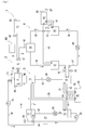
FIG. 1] FIG. 1 is a system block diagram showing an overall configuration of acogeneration system 1 according to the present invention. - [
FIG. 2] FIG. 2 is a control block diagram of the same. - [
FIG. 3] FIG. 3 is an energy flowchart of the same. - [
FIG. 4] FIG. 4 is an explanatory diagram showing formulas of a balance electricity of the same. - [
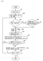
FIG. 5] FIG. 5 is a flowchart showing an operation procedure of the same. - [
FIG. 6] FIG. 6 is a system block diagram showing an overall configuration of acogeneration system 1A according to another embodiment. - [
FIG. 7] FIG. 7 is an energy flowchart of the same. - [
FIG. 8] FIG. 8 is a flowchart showing an operation procedure of the same. -
- 1 Cogeneration system
- 3 Thermally driven heat pump
- 4 Thermally-driven-heat-pump assisted electrically driven heat pump
- 4A Electrically driven heat pump
- 5 Gas engine (engine)
- 44 Controller (operation controller)
- De1 Electricity demand
- De2, De3 Required electricity
- Dh Heat demand
- e Generated electricity
- eb Balance electricity (sum of electricity demand and required electricity)
- h Output heat from gas engine (output heat from engine)
- h3, h5 Heat from electrically driven heat pump
- h4 Heat from thermally driven heat pump
- Now, embodiments of the invention will be described.
First, an overall configuration of the cogeneration system according to the present invention is described with reference toFIG. 1 andFIG. 2 . - The
cogeneration system 1 includes acogeneration device 2 that supplies electricity and heat, a thermally drivenheat pump 3 driven through thermal regeneration of an absorbent solution that has absorbed a refrigerant, a thermally-driven-heat-pump assisted electrically driven heat pump 4 of a compression type driven through compression of the refrigerant, and acontroller 44 that controls the elements. - Of the elements, the
cogeneration device 2 includes agas engine 5 that is a reciprocating internal combustion engine and agenerator 6 having aninput shaft 43 coupled to anoutput shaft 7 of thegas engine 5 in such a manner as to be capable of moving in conjunction with each other. Thegenerator 6 is coupled to an electricity consumingdevice group 10 including lighting equipment and the like, and to the thermally-driven-heat-pump assisted electrically driven heat pump 4 through apower converter 47 such as an inverter and anelectrical circuit 9. Thus, the electricity generated by thegenerator 6 is supplied to the energy consumingdevice group 10 and the thermally-driven-heat-pump assisted electrically driven heat pump 4. - The
gas engine 5 is provided, in its housing and the like, with a coolingwater path 11 for cooling water and anexhaust gas path 12. The exhaustgas exhaust path 12 is provided with, at an intermediate portion, an exhaustgas heat exchanger 13 with which thecooling water path 11 communicates. Theexhaust gas exchanger 13 and the coolingwater path 11 are coupled to the thermally drivenheat pump 3 through aflow path 14 provided with a coolingwater pump 15 at an intermediate portion. - In such a configuration, the cooling water heated by the heat of the
gas engine 5 while flowing through the coolingwater path 11 is further heated at the exhaustgas heat exchanger 13 by the hot exhaust gas sent from thegas engine 5 through theexhaust gas path 12, and then is pumped to the thermally drivenheat pump 3 by the coolingwater pump 15. Thus, the output heat from thegas engine 5 is supplied to the thermally drivenheat pump 3 via the cooling water. - The thermally driven
heat pump 3, for example, uses water as the refrigerant and lithium bromide-water solution as an absorbent, and includes anabsorber 16, aregenerator 17, acondenser 18, anevaporator 19,flow paths - Of the units, the
absorber 16 is coupled to theevaporator 19 through theflow path 23. Refrigerant vapor generated by evaporation in theevaporator 19 is absorbed by the absorbent in theabsorber 16 through theflow path 23 and thus an absorbent solution is formed. Furthermore, theabsorber 16 is coupled to theregenerator 17 through theflow path 24 provided with asolution pump 28 at an intermediate portion, so that the absorbent solution is pumped to theregenerator 17 through theflow path 24 and reserved therein. - The
flow path 14 is coupled to theregenerator 17. The reserved absorbent solution is heated by the heat of the cooling water flowing through theflow path 14. Thus, the refrigerant in the absorbent solution is separated as the refrigerant vapor, whereby the absorbent solution is condensed. Furthermore, theregenerator 17 is coupled to theabsorber 16 through theflow path 20 provided with adecompression mechanism 29 at an intermediate portion, and thus the thermally condensed low pressure absorbent solution is supplied to theabsorber 16 through theflow path 20. Asolution heat exchanger 27 is disposed between theflow path 20 and theflow path 24. Through thesolution heat exchanger 27, the absorbent solution pumped from theabsorber 16 to theregenerator 17 is heated partly through the way so that the thermal separation of the refrigerant in theregenerator 17 is facilitated. - The
condenser 18 is coupled to theregenerator 17 through theflow path 21. Thus, the refrigerant vapor from theregenerator 17 is introduced into thecondenser 18 through theflow path 21 to be condensed into the refrigerant. Furthermore, thecondenser 18 is coupled to theevaporator 19 through theflow path 22 provided with adecompression mechanism 30 at an intermediate portion. Thus, the condensed low pressure refrigerant is supplied to theevaporator 19 through theflow path 22. - The
evaporator 19 is coupled to a low-gradeheat device group 26 including a water heater and the like through aflow path 31. The heating medium flowing through theflow path 31 is deprived of heat and thus is cooled as the low pressure refrigerant from thecondenser 18 evaporates. Here, theabsorber 16 is decompressed as the refrigerant vapor is absorbed by the absorbent and thus the pressure therein is extremely low. Theevaporator 19 communicated with theabsorber 16 through theflow path 23 is also maintained at a low pressure. Thus, the refrigerant from thecondenser 18 is readily vaporized only by the heat of the heating medium flowing through theflow path 31, to flow through theflow path 23 as the refrigerant vapor to be supplied to theabsorber 16. - An absorption heat cycle of the thermally driven
heat pump 3 is thus configured. As the refrigerant in the absorption heat cycle transforms, heat is generated by the absorbed heat and the condensed heat respectively in theabsorber 16 and thecondenser 18, and cooling is generated by the evaporation heat in theevaporator 19. Here, theabsorber 16 and thecondenser 18 are also coupled to the low-grade heatutilization device group 26 through theflow path 25, and thus the cooling and the heat can be supplied to the low-gradeheat device group 26 respectively through theflow path 31 and theflow path 25. - The thermally-driven-heat-pump assisted electrically driven heat pump 4, for example, uses hydrofluorocarbon as the refrigerant, and includes a
compressor 32, acondenser 33, adecompression mechanism 34 such as an expansion valve, anevaporator 35,flow paths - Of the units, the
compressor 32 is coupled to theevaporator 35 through theflow path 39. The cold-low pressure refrigerant vapor produced by the evaporation in theevaporator 35 flows to thecompressor 32 through theflow path 39 to be compressed into hot-high pressure refrigerant vapor. Thecompressor 32 is coupled to theelectrical circuit 9 and thus can be electrically driven by a part of the electricity generated by thegenerator 6. - The
condenser 33 is coupled to thecompressor 32 through theflow path 36. The hot-high pressure refrigerant vapor from thecompressor 32 is introduced into thecondenser 33 through theflow path 36 to be condensed into a refrigerant. - The
decompression mechanism 34 is coupled to thecondenser 33 through theflow path 37 provided with theevaporator 19 of the thermally drivenheat pump 3 at an intermediate portion. The refrigerant from thecondenser 33 is decompressed by thedecompression mechanism 34 after being supercooled beforehand by the heat exchange in theevaporator 19. Thedecompression mechanism 34 is coupled to theevaporator 35 through theflow path 38, and the supercooled low pressure refrigerant is supplied to theevaporator 35 through theflow path 38. - The
evaporator 35 is coupled to a high-grade heatutilization device group 42 such as a freezer, a refrigerator, and an air conditioner through aflow path 41. The low pressure refrigerant from thedecompression mechanism 34 is heated and thus evaporated by the heating medium flowing through theflow path 41, into a cold-low pressure refrigerant vapor to flow through theflow path 39 to be supplied into thecompressor 32. - The compression heat cycle of the thermally-driven-heat-pump assisted electrically driven heat pump 4 is thus configured. As the refrigerant in the compression heat cycle transforms, heat is generated by the condensed heat in the
condenser 33, and cooling is generated by the evaporation heat in theevaporator 35. Here, thecondenser 33 is also coupled to the high-grade heatutilization device group 42 through aflow path 40, and thus the cooling and the heat can be supplied to the high-grade heatutilization device group 42 respectively through theflow path 41 and theflow path 40. - Furthermore, as described above, in the thermally-driven-heat-pump assisted electrically driven heat pump 4, the refrigerant flowing between the
condenser 33 and thedecompression mechanism 34 is supercooled by the cooling generated in theevaporator 19 of the thermally drivenheat pump 3 to have a lower enthalpy. Thus, the cycle efficiency of the compression heat cycle is improved, and thus the pump efficiency of the electrical driven heat pump is largely improved. - The
controller 44 is coupled to anelectricity sensor 48 disposed at an input portion of the electricity consumingdevice group 10, anelectricity sensor 49 disposed at an input portion of thecompressor 32 of the thermally-driven-heat-pump assisted electrically driven heat pump 4, awater temperature sensor 59 that detects the temperature of the cooling water in theflow path 14 leading to the thermally drivenheat pump 3, a mediumtemperature sensor group 50 that detects the temperature of the heating medium introduced to the low-grade heatutilization device group 26, anambient temperature sensor 54 that detects the ambient temperature around the low-grade heatutilization deice group 26,medium temperature sensors flow path 37 of the thermally-driven-heat-pump assisted electrically driven heat pump 4, a mediumtemperature sensor group 53 that detects the heating medium introduced into the high-grade heatutilization device group 42, and anambient temperature sensor 57 that detects the ambient temperature around the high-grade heatutilization device group 42. Detection signals from the sensors are inputted to thecontroller 44. - Furthermore, the
controller 44 is coupled to anengine switch 45 that drives or stops thegas engine 5, anengine output controller 46 that controls a rotation speed of theoutput shaft 7 of thegas engine 5, thepower converter 47 such as an inverter that controls the electricity outputted to thecompressor 32 of the thermally-driven-heat-pump assisted electrically driven heat pump 4 from thegenerator 6, anelectricity setter 58 that sets the electricity consumed by the electricity consumingdevice group 10, atemperature setter 55 that sets an output temperature (hereinafter referred to "temperature of heat demand") from the low-grade heatutilization device group 26, atemperature setter 56 that sets the temperature of heat demand of the high-grade heatutilization device group 42, the coolingwater pump 15 between thegas engine 5 and the thermally drivenheat pump 3, thesolution pump 28 of the thermally drivenheat pump 3, and thecompressor 32 of the thermally-driven-heat-pump assisted electrically driven heat pump 4. On the basis of the detection values obtained from the detection signals, thecontroller 44 outputs driving signals. - Next, the energy flow in the
cogeneration system 1 having the configuration described above will be described with reference toFIG. 1 ,FIG. 3 andFIG. 4 .
As shown inFIG. 1 andFIG. 3 , heat and electricity are outputted from thecogeneration device 2 at a thermoelectric ratio R (=output heat h/generated electricity e). - Of the values, the output heat h is supplied to the
regenerator 17 of the thermally drivenheat pump 3 in a form of heat as described above. Thus, the absorbent solution reserved in theregenerator 17 is heated, whereby the absorption heat cycle is started. Accordingly, the output heat h is converted into the heat in theabsorber 16 and thecondenser 18 of the thermally drivenheat pump 3, and then is converted into the cooling in theevaporator 19. - A part of these heat and cooling is supplied to the heat demand Dh1 of the low-grade heat
utilization device group 26 as heat h1, and the rest is supplied as heat h2 for the supercooling of the refrigerant in the thermally-driven-heat-pump assisted electrically driven heat pump 4. - Here, a part of the generated electricity e is supplied as generated electricity e1 to the electricity demand De1 of the electricity consuming
device group 10, and the rest is supplied as generated electricity e2 to the electricity demand De2 of thecompressor 32 of the thermally-driven-heat-pump assisted electrically driven heat pump 4. Thus, thecompressor 32 is driven so that the cold-low pressure refrigerant vapor is compressed, whereby the compression heat cycle is started. - Thus, as described above, the heat is produced in the
condenser 33, and the cooling is produced in theevaporator 35. The heat and the cooling are supplied as the sum of the heat h2 and the heat h3 to the heat demand Dh2 of the high-grade heatutilization device group 42. Here, the heat h3 represents the heat and cooling produced in the thermally-driven-heat-pump assisted electrically driven heat pump 4 in a case without the supercooling in the thermally drivenheat pump 3. - In
FIG. 4 , a balance between heat and electricity in the energy flow is described inFormula 61, and a value obtained by solvingFormula 61 for the generated electricity eb in the balanced state (hereinafter referred to as "balance electricity") is described inFormula 62. - As described above, De1 denotes the electricity demand of the electricity consuming
device group 10, Dh1 the heat demand of the low-grade heatutilization device group 26, Dh2 the heat demand of the high-grade heatutilization device group 42, and R the thermoelectric ratio. Moreover, Acop denotes the pump efficiency of the thermally drivenheat pump 3 and Hcop the pump efficiency of the electrically driven heat pump 4. - Thus, by performing the electricity control in such manner that the generated electricity e of the
gas engine 5 becomes equal to the balance electricity eb shown inFormula 62 including the heat demand De1, the heat demands Dh1 and Dh2, the thermoelectric ratio R, and the pump efficiencies Acop and Hcop, an operation (hereinafter referred to as "highly efficient operation") can be performed in which the amount of electricity and heat supplied from thecogeneration device 2 and the heat electricity demand of the electricity consumingdevice group 10 and the heatutilization device groups - Next, an operation control procedure of the
cogeneration system 1 involving the energy flow as described above will be described with reference toFIG. 1 to FIG. 5 , mainlyFIG. 5 .
First, when theengine switch 45 is turned "ON" to drive the gas engine 5 (Step S1), an engine driving signal is inputted into thecontroller 44, and a pump driving signal is transmitted from thecontroller 44 to the coolingwater pump 15 and thesolution pump 28, whereby the thermally drivenheat pump 3 is driven (Step S2). - When the absorption heat cycle is thus started, the detected temperature signal from the medium
temperature sensor group 50 and the set temperature signals from thetemperature setter controller 44. In thecontroller 44, the heat h4 (=h1+h2) outputted from the thermally drivenheat pump 3 and the heat demand Dh (=Dh1+Dh2) of the heatutilization device groups - On the contrary, if the heat demand Dh does not exceed the heat h4 (Step S3, NO), the detected temperature signals from the
ambient temperature sensors controller 44. In thecontroller 44, the temperature T4 of the heat h4 outputted from the thermally drivenheat pump 3, the ambient temperature Ta around the heatutilization device groups utilization device groups - If the heat demand Dh does not exceed the heat h4 and the temperature Th of the heat demand Dh does not exceed the temperature T4 of the heat h4 (Step S4, NO), the normal electricity focused operation or heat focused operation is performed (Step S10).
- When the highly efficient operation starts, the driving signals are transmitted from the
controller 44 to theengine output controller 46 and thepower converter 47. Then, the electricity is transmitted from thegenerator 6 to thecompressor 32, whereby the thermally-driven-heat-pump assisted electrically driven heat pump 4 is driven (Step S6). - When the compression heat cycle thus starts, the
controller 44 receives the detected electricity signals from theelectricity sensors electricity setter 58, and the detected temperature signals from thewater temperature sensor 59 and the mediumtemperature sensor groups controller 44, the actually generated electricity e (=e1+e2) outputted from thegenerator 6, the electricity demand De1, and the pump efficiencies Acop and Hcop are calculated. - By substituting the heat demands Dh1 and Dh2 that have been calculated and the thermoelectric ratio R that is a set value as well as the electricity demand De1 and the pump efficiencies Acop and Hcop into
Formula 62, the balance electricity eb is calculated. Theengine output controller 46 and thepower converter 47 are controlled in such a manner that the generated electricity e is set to the balance electricity eb (=De1+De2) (Step S7). Thus, the heat demand Dh2 of the high-grade heatutilization device group 42 requiring a detailed temperature control can be satisfied. - Then, the
controller 44 receives the detected temperature signals from themedium temperature sensors controller 44, the supplied temperature Th2 to the high-grade heatutilization device group 42 and an assist amount As of thermally drivenheat pump 3 to the thermally-driven-heat-pump assisted electrically driven heat pump 4 are calculated. Through modifying the assist amount As, the supplied temperature Th2 and the pump efficiency Hcop that have been calculated are maximized with respect to the heat demand Dh (Step S8). The assist amount As is obtained from the difference between the temperatures detected by themedium temperature sensors - When the generated electricity e is below the maximum electricity generation capacity em of the cogeneration device 2 (Step S9, YES), the process returns to Step S3. On the contrary, if the generated electricity e is equal to or higher than the maximum electricity generation capacity em of the cogeneration device 2 (Step S9, NO), the conventional electricity focused operation or the heat focused operation is performed (Step S10). The process repeatedly returns to Step S3 so that the operation control is repeated until the
gas engine 5 stops (Step S11, YES). - Specifically, as described above, in the
cogeneration system 1 configured to supply electricity and heat with thegas engine 5 as an engine and including the thermally drivenheat pump 3 and the thermally-driven-heat-pump assisted electric heat pump 4 as an electrically driven heat pump, thecontroller 44 as an operation controller configured to perform an electricity control in such a manner that the generated electricity e of thegas engine 5 becomes equal to the balance electricity eb as the sum of the required electricity De2 for driving the thermally-driven-heat-pump assisted electrically driven heat pump 4 configured to compensate the heat demand Dh of thecogeneration system 1 and the electricity demand De1 of thecogeneration system 1, is provided. Thus, the predetermined electricity demand De1 of thecogeneration system 1, and the required electricity De2 for driving the thermally-driven-heat-pump assisted electrically driven heat pump 4 are satisfied by increasing/reducing the generated electricity e of thegas engine 5. The heat demand Dh2 as high-grade heat demand of thecogeneration system 1 can be satisfied by adjusting the heat h2 and h3 outputted as the thermally-driven-heat-pump assisted electrically driven heat pump 4 is driven. Thus, the electricity demand De1 and the heat demand Dh can be satisfied as accurately as possible within thecogeneration system 1 only, and the energy cost can be made low. - Furthermore, in the
controller 44 as the operation controller, a thermally-driven-heat-pump focused serial operation is performed in which the output heat h from thegas engine 5 is entirely inputted to the thermally drivenheat pump 3, and a difference between the heat h4 from the thermally drivenheat pump 3 and the heat demand Dh of thecogeneration system 1 is compensated by the heat h3 from the thermally-driven-heat-pump assisted electrically driven heat pump 4. Thus, a large amount of the output heat h outputted from thegas engine 5 is efficiently utilized so that a less amount of heat h3 needs to be compensated by the thermally-driven-heat-pump assisted electrically driven heat pump 4. Thus, the electricity required for the driving can be minimized, thereby allowing thegas engine 5 with a low power generation capacity to satisfy a large amount of electricity demand De1. Accordingly, an attempt to reduce the device cost of thecogeneration system 1 is facilitated. - Furthermore, the electrically driven heat pump includes the thermally-driven-heat-pump assisted electrically driven heat pump 4 in which a refrigerant exchanges heat with the heat from the thermally driven
heat pump 3. Thus, the pump efficiency Hcop of the thermally-driven-heat-pump assisted electrically driven heat pump 4 can be largely improved by using only a part of the heat from the thermally drivenheat pump 3. Thus, compared with a case where the heat is independently taken out from the thermally drivenheat pump 3 and the thermally-driven-heat-pump assisted electrically drivenheat pump 4A to satisfy the heat demand Dh, the heat efficiency and the heating/cooling capacity of thecogeneration system 1 as a whole can be improved. - In the thermally-driven-heat-pump assisted electrically driven heat pump 4 of this embodiment, the refrigerant liquid obtained by condensing the refrigerant vapor in the
condenser 33 is supercooled to have a lower enthalpy while flowing through thevaporizer 19 of the thermally drivenheat pump 3. Alternatively, thecondenser 33 can be omitted so that the refrigerant vapor flows in thevaporizer 19 of the thermally drivenheat pump 3 as it is. The configuration is not particularly limited as long as the heat from the thermally drivenheat pump 3 cools the refrigerant. Here, the refrigerant vapor is repeatedly condensed and supercooled, whereby the heat loss of the flowing refrigerant can be largely reduced, and thus the pump efficiency Hcop of the thermally-driven-heat-pump assisted electrically driven heat pump 4 can be further improved. - Next, a
cogeneration system 1A according to another embodiment will be described with reference toFIG. 6 to FIG. 8 . Elements and configuration similar to those in thecogeneration 1 are denoted with the same reference numerals and the detail description thereof is omitted. - As shown in
FIG. 6 , thecogeneration system 1A is formed by replacing the thermally-driven-heat-pump assisted electrically driven heat pump 4 in thecogeneration system 1 by an electrically drivenheat pump 4A that can independently be driven without the assist from the thermally drivenheat pump 3. - Other configuration is the same as that of the
cogeneration system 1, and thecogeneration system 1A includes the electrically drivenheat pump 4A having the different configuration, as well as thecogeneration device 2, the thermally drivenheat pump 3, and thecontroller 44 that controls these elements. - The electrically driven
heat pump 4A, like the thermally-driven-heat-pump assisted electrically driven heat pump 4, includes thecompressor 32, thecondenser 33, thedecompression mechanism 34 such as an expansion valve, theevaporator 35,flow paths flow path 37A is not provided with thevaporizer 19 of the thermally drivenheat pump 3, unlike theflow path 37. Thus, thecondenser 33 and thedecompression mechanism 34 are directly coupled, and the refrigerant fluid is sent to from thecondenser 33 to thedecompression mechanism 34 as it is. Thus, the refrigerant is not supercooled part way through to have a lower enthalpy. - As shown in
FIG. 7 , in thecogeneration system 1A having the above described configuration, unlike in thecogeneration system 1, the output heat h from thegas engine 5 is converted into the heat h4 in the thermally drivenheat pump 3, and then is entirely supplied to the heat demand Dh1 of the low-grade heatutilization device group 26. - Meanwhile, as in the
cogeneration system 1, a part of the generated electricity e is supplied as the generated electricity e1 to the electricity demand De1 of the electricity consumingdevice group 10, and the rest of the generated electricity e is supplied as the generated power e2 to the required electricity De3 of thecompressor 32 of the electrically drivenheat pump 4A. Thus, thecompressor 32 is driven and the cold-low pressure refrigerant vapor is compressed, whereby the compression heat cycle starts. - Then, the required electricity De3 is converted into the heat h5 in the electrically driven
heat pump 4A, and then is supplied to the heat demand Dh2 of the high-grade heatutilization device group 42. - As shown in
FIG. 8 , in thecogeneration system 1A involving such an energy flow, first, when theengine switch 45 is turned "ON" so that thegas engine 5 is driven (Step S21), the thermally drivenheat pump 3 is driven (Step S22). - When the absorption heat cycle is thus started, the heat h4 outputted from the thermally driven
heat pump 3 and the heat demand Dh of the heatutilization device groups - The highly efficient operation also starts (Step S25), when the heat demand Dh does not exceed the heat h4 (Step S23, NO), and the temperature Th of the heat demand Dh of the
heat utilization devices - When the highly efficient operation starts, the electricity is sent from the
generator 6 to thecompressor 32, and the electrically drivenheat pump 4A is driven (Step S26). - When the compression heat cycle is thus started, in the
controller 44, an operation control is performed in such a manner that the actual generated electricity e outputted from thegenerator 6 is set to the balance electricity eb (=De1+De3) calculated by Formula 62 (Step S27). - When the generated electricity e is below the maximum electricity generation capacity em of the cogeneration device 2 (Step S28, YES), the process returns to Step S23. On the contrary, when the generated electricity e is equal to or higher than the maximum electricity generation capacity em of the cogeneration device 2 (Step S28, NO), the conventional electricity focused operation or heat focused operation is performed (Step S29). The process repeatedly returns to Step S23 so that the operation control is repeated until the
gas engine 5 stops (Step S30, YES). - Specifically, as described above, the electrically driven
heat pump 4A and the thermally drivenheat pump 3 are coupled to each other in parallel, and theheat pumps heat pump 4A requires no high pump efficiency, the electricity demand De1 and the heat demand Dh can be satisfied, as accurately as possible, within thecogeneration system 1A only, whereby the energy cost can be made small. Furthermore, a communication path between theheat pumps - The present invention can be applied to any cogeneration system that supplies electricity and heat with an engine.
Claims (3)
- A cogeneration system configured to supply electricity and heat with an engine, comprising:a thermally driven heat pump; andan electrically driven heat pump,wherein an operation controller configured to perform electricity control in such a manner that generated electricity of the engine becomes equal to the sum of required electricity for driving an electrically driven heat pump configured to compensate heat demand of the cogeneration system and electricity demand of the cogeneration system, is provided.
- The cogeneration system according to claim 1, wherein in the operation controller, a thermally-driven-heat-pump focused serial operation is performed in which output heat from the engine is entirely inputted to the thermally driven heat pump, and a difference between heat from the thermally driven heat pump and heat demand of the cogeneration system is compensated by heat from the electrically driven heat pump.
- The cogeneration system according to claim 1 or 2, wherein the electrically driven heat pump comprises a thermally-driven-heat-pump assisted electrically driven heat pump in which a refrigerant exchanges heat with heat from the thermally driven heat pump.
Applications Claiming Priority (2)
| Application Number | Priority Date | Filing Date | Title |
|---|---|---|---|
| JP2011012157A JP5636297B2 (en) | 2011-01-24 | 2011-01-24 | Cogeneration system |
| PCT/JP2012/051181 WO2012102197A1 (en) | 2011-01-24 | 2012-01-20 | Cogeneration system |
Publications (2)
| Publication Number | Publication Date |
|---|---|
| EP2669499A1 true EP2669499A1 (en) | 2013-12-04 |
| EP2669499A4 EP2669499A4 (en) | 2016-02-17 |
Family
ID=46580766
Family Applications (1)
| Application Number | Title | Priority Date | Filing Date |
|---|---|---|---|
| EP12738955.9A Withdrawn EP2669499A4 (en) | 2011-01-24 | 2012-01-20 | COGENERATION SYSTEM |
Country Status (4)
| Country | Link |
|---|---|
| US (1) | US9476620B2 (en) |
| EP (1) | EP2669499A4 (en) |
| JP (1) | JP5636297B2 (en) |
| WO (1) | WO2012102197A1 (en) |
Cited By (4)
| Publication number | Priority date | Publication date | Assignee | Title |
|---|---|---|---|---|
| EP2669499A4 (en) * | 2011-01-24 | 2016-02-17 | Yanmar Co Ltd | COGENERATION SYSTEM |
| ITUA20161730A1 (en) * | 2016-03-16 | 2017-09-16 | Stefano Briola | PLANT AND METHOD FOR SUPPLY TO THE USER OF ELECTRIC POWER AND / OR MECHANICAL POWER, THERMAL POWER AND / OR REFRIGERANT POWER |
| FR3086039A1 (en) * | 2018-09-18 | 2020-03-20 | Commissariat A L'energie Atomique Et Aux Energies Alternatives | SYSTEM FOR THE PRODUCTION AND MANAGEMENT OF COLD BY AN ABSORPTION MACHINE FROM FATAL ENERGY OF A COMBUSTION ENGINE |
| EP3919836A1 (en) * | 2020-06-03 | 2021-12-08 | Commissariat à l'énergie atomique et aux énergies alternatives | Thermal system comprising at least one circuit of an absorption machine having improved performance |
Families Citing this family (6)
| Publication number | Priority date | Publication date | Assignee | Title |
|---|---|---|---|---|
| JP2015068333A (en) * | 2013-10-01 | 2015-04-13 | ヤンマー株式会社 | Cogeneration device |
| US9630474B2 (en) * | 2013-10-29 | 2017-04-25 | Denso International America, Inc. | Thermostatic controlled heat pump water circuit |
| US11041637B2 (en) * | 2017-06-27 | 2021-06-22 | Imby Energy, Inc. | Cogeneration systems and methods for generating heating and electricity |
| CN108387029A (en) * | 2018-04-04 | 2018-08-10 | 山东大学 | A kind of hotspot stress flexible controllable novel cooling heating and power generation system and control method |
| AT522615A1 (en) * | 2019-05-29 | 2020-12-15 | Ait Austrian Inst Tech Gmbh | Process for generating steam |
| CN114061173A (en) * | 2022-01-13 | 2022-02-18 | 华电电力科学研究院有限公司 | Energy cascade utilization system and method for multi-energy complementary distributed energy system |
Family Cites Families (21)
| Publication number | Priority date | Publication date | Assignee | Title |
|---|---|---|---|---|
| US4380909A (en) * | 1981-07-17 | 1983-04-26 | Chevron Research Company | Method and apparatus for co-generation of electrical power and absorption-type heat pump air conditioning |
| US4802100A (en) * | 1986-08-18 | 1989-01-31 | Gas Research Institute | Advanced cogeneration control system |
| US4813242A (en) * | 1987-11-17 | 1989-03-21 | Wicks Frank E | Efficient heater and air conditioner |
| JPH0854156A (en) * | 1993-12-27 | 1996-02-27 | Ebara Corp | Cooling and heating device utilizing exhaust heat of engine and operating method thereof |
| JP3640686B2 (en) | 1994-06-27 | 2005-04-20 | 東京瓦斯株式会社 | Cogeneration system |
| JPH0886533A (en) | 1994-09-16 | 1996-04-02 | Toshiba Corp | Air conditioner |
| JP3215279B2 (en) * | 1995-03-15 | 2001-10-02 | 三菱電機株式会社 | Method and apparatus for operating energy equipment |
| JPH0926226A (en) * | 1995-07-11 | 1997-01-28 | Nkk Corp | Refrigeration equipment |
| JP2983489B2 (en) * | 1997-04-10 | 1999-11-29 | 川崎重工業株式会社 | Operation control method of heat source equipment |
| JP4186245B2 (en) | 1998-02-04 | 2008-11-26 | ダイキン工業株式会社 | Refrigeration equipment |
| FI107183B (en) * | 1999-02-24 | 2001-06-15 | Goeran Vilhelm Vikstroem | Optimized regional thermal power generation method for combined heat and power and optimized regional thermal power plant |
| JP2002256970A (en) * | 2001-02-26 | 2002-09-11 | Kubota Corp | Cogeneration system |
| JP4089187B2 (en) * | 2001-08-31 | 2008-05-28 | 株式会社日立製作所 | Thermoelectric supply system |
| JP2003075017A (en) * | 2001-09-04 | 2003-03-12 | Sanyo Electric Co Ltd | Exhaust heat utilizing refrigerating system |
| JP3763767B2 (en) * | 2001-10-02 | 2006-04-05 | 株式会社東芝 | Operation planning system for energy supply equipment |
| JP3719592B2 (en) | 2001-10-10 | 2005-11-24 | 東京瓦斯株式会社 | Combined air conditioning unit |
| US7037360B2 (en) * | 2002-08-15 | 2006-05-02 | Mitsubishi Chemical Corporation | Adsorbent for heat utilization system, adsorbent for regenerator system, regenerator system comprising the adsorbent, ferroaluminophosphate and method for production thereof |
| KR100550575B1 (en) * | 2004-08-17 | 2006-02-10 | 엘지전자 주식회사 | Power generation air conditioning system with dehumidifier |
| KR100644826B1 (en) * | 2004-12-10 | 2006-11-10 | 엘지전자 주식회사 | Cogeneration System |
| KR100649596B1 (en) * | 2004-12-10 | 2006-11-28 | 엘지전자 주식회사 | Cogeneration System |
| JP5636297B2 (en) * | 2011-01-24 | 2014-12-03 | ヤンマー株式会社 | Cogeneration system |
-
2011
- 2011-01-24 JP JP2011012157A patent/JP5636297B2/en not_active Expired - Fee Related
-
2012
- 2012-01-20 EP EP12738955.9A patent/EP2669499A4/en not_active Withdrawn
- 2012-01-20 US US13/981,255 patent/US9476620B2/en not_active Expired - Fee Related
- 2012-01-20 WO PCT/JP2012/051181 patent/WO2012102197A1/en not_active Ceased
Cited By (9)
| Publication number | Priority date | Publication date | Assignee | Title |
|---|---|---|---|---|
| EP2669499A4 (en) * | 2011-01-24 | 2016-02-17 | Yanmar Co Ltd | COGENERATION SYSTEM |
| ITUA20161730A1 (en) * | 2016-03-16 | 2017-09-16 | Stefano Briola | PLANT AND METHOD FOR SUPPLY TO THE USER OF ELECTRIC POWER AND / OR MECHANICAL POWER, THERMAL POWER AND / OR REFRIGERANT POWER |
| WO2017158511A1 (en) * | 2016-03-16 | 2017-09-21 | Briola Stefano | Plant and method for the supply of electric power and/or mechanical power, heating power and/or cooling power |
| CN108779685A (en) * | 2016-03-16 | 2018-11-09 | 斯特凡诺·布里奥拉 | Device and method for supplying electrical and/or mechanical, heating and/or cooling power |
| US10794232B2 (en) | 2016-03-16 | 2020-10-06 | Stefano BRIOLA | Plant and method for the supply of electric power and/or mechanical power, heating power and/or cooling power |
| FR3086039A1 (en) * | 2018-09-18 | 2020-03-20 | Commissariat A L'energie Atomique Et Aux Energies Alternatives | SYSTEM FOR THE PRODUCTION AND MANAGEMENT OF COLD BY AN ABSORPTION MACHINE FROM FATAL ENERGY OF A COMBUSTION ENGINE |
| EP3627070A1 (en) * | 2018-09-18 | 2020-03-25 | Commissariat à l'Energie Atomique et aux Energies Alternatives | System for producing and managing refrigeration by an absorption machine from residual energy derived from a combustion engine |
| EP3919836A1 (en) * | 2020-06-03 | 2021-12-08 | Commissariat à l'énergie atomique et aux énergies alternatives | Thermal system comprising at least one circuit of an absorption machine having improved performance |
| FR3111185A1 (en) * | 2020-06-03 | 2021-12-10 | Commissariat A L'energie Atomique Et Aux Energies Alternatives | THERMAL SYSTEM INCLUDING AT LEAST ONE ABSORPTION MACHINE CIRCUIT WITH IMPROVED PERFORMANCE |
Also Published As
| Publication number | Publication date |
|---|---|
| EP2669499A4 (en) | 2016-02-17 |
| JP2012154203A (en) | 2012-08-16 |
| US20140013785A1 (en) | 2014-01-16 |
| WO2012102197A1 (en) | 2012-08-02 |
| JP5636297B2 (en) | 2014-12-03 |
| US9476620B2 (en) | 2016-10-25 |
Similar Documents
| Publication | Publication Date | Title |
|---|---|---|
| US9476620B2 (en) | Cogeneration system | |
| US10030646B2 (en) | Gas compressor | |
| US20060026981A1 (en) | Refrigerating device comprising waste heat utilization equipment | |
| KR20030004026A (en) | Variable speed drive chiller system | |
| JP2011012625A (en) | Exhaust heat recovery system and control method of the same | |
| JP2021513720A5 (en) | ||
| JP4471992B2 (en) | Multi-source heat pump steam / hot water generator | |
| KR20060065875A (en) | Cogeneration System | |
| KR100732228B1 (en) | Hybrid Absorption Chiller | |
| JP2014190586A (en) | Ejector type refrigeration cycle device | |
| KR100814615B1 (en) | Cogeneration System Using Absorption and Compression Cycles | |
| US11788776B2 (en) | Refrigeration unit | |
| CN111536666B (en) | Air conditioning system | |
| JP4152140B2 (en) | Waste heat absorption refrigerator | |
| JP5907812B2 (en) | Heat pump system and operation method thereof | |
| WO2012064208A1 (en) | Method for converting low temperature thermal energy into high temperature thermal energy and mechanical energy and a heat pump device for such conversion | |
| JP2012141097A (en) | Heat source system and control method therefor | |
| CN114440493A (en) | Coupling unit, and control method and control system of coupling unit | |
| JP4535451B2 (en) | Cold and hot water system | |
| JP4546188B2 (en) | Waste heat utilization air conditioning system | |
| JP2005055150A (en) | Operation method and control device of air conditioner | |
| KR20150095756A (en) | Heat pump energy supply optimization and system | |
| JPH04251170A (en) | Refrigerating device and operation method thereof in cogeneration system | |
| JP2019152347A (en) | Chiller system | |
| JP2015071982A (en) | Control device of gas engine |
Legal Events
| Date | Code | Title | Description |
|---|---|---|---|
| PUAI | Public reference made under article 153(3) epc to a published international application that has entered the european phase |
Free format text: ORIGINAL CODE: 0009012 |
|
| 17P | Request for examination filed |
Effective date: 20130826 |
|
| AK | Designated contracting states |
Kind code of ref document: A1 Designated state(s): AL AT BE BG CH CY CZ DE DK EE ES FI FR GB GR HR HU IE IS IT LI LT LU LV MC MK MT NL NO PL PT RO RS SE SI SK SM TR |
|
| DAX | Request for extension of the european patent (deleted) | ||
| RA4 | Supplementary search report drawn up and despatched (corrected) |
Effective date: 20160114 |
|
| RIC1 | Information provided on ipc code assigned before grant |
Ipc: F25B 27/02 20060101ALI20160108BHEP Ipc: F25B 25/02 20060101ALI20160108BHEP Ipc: F25B 15/00 20060101ALI20160108BHEP Ipc: F02G 5/04 20060101AFI20160108BHEP |
|
| STAA | Information on the status of an ep patent application or granted ep patent |
Free format text: STATUS: EXAMINATION IS IN PROGRESS |
|
| 17Q | First examination report despatched |
Effective date: 20170206 |
|
| RAP1 | Party data changed (applicant data changed or rights of an application transferred) |
Owner name: YANMAR POWER TECHNOLOGY CO., LTD. |
|
| GRAP | Despatch of communication of intention to grant a patent |
Free format text: ORIGINAL CODE: EPIDOSNIGR1 |
|
| STAA | Information on the status of an ep patent application or granted ep patent |
Free format text: STATUS: GRANT OF PATENT IS INTENDED |
|
| INTG | Intention to grant announced |
Effective date: 20210518 |
|
| STAA | Information on the status of an ep patent application or granted ep patent |
Free format text: STATUS: THE APPLICATION IS DEEMED TO BE WITHDRAWN |
|
| 18D | Application deemed to be withdrawn |
Effective date: 20210929 |