EP2669495A1 - Method for operating a multi-cylinder internal combustion engine - Google Patents
Method for operating a multi-cylinder internal combustion engine Download PDFInfo
- Publication number
- EP2669495A1 EP2669495A1 EP12170541.2A EP12170541A EP2669495A1 EP 2669495 A1 EP2669495 A1 EP 2669495A1 EP 12170541 A EP12170541 A EP 12170541A EP 2669495 A1 EP2669495 A1 EP 2669495A1
- Authority
- EP
- European Patent Office
- Prior art keywords
- cylinder
- exhaust
- exhaust valve
- opening
- valve
- Prior art date
- Legal status (The legal status is an assumption and is not a legal conclusion. Google has not performed a legal analysis and makes no representation as to the accuracy of the status listed.)
- Withdrawn
Links
- 238000002485 combustion reaction Methods 0.000 title claims abstract description 22
- 238000000034 method Methods 0.000 title claims description 18
- 230000009849 deactivation Effects 0.000 claims description 4
- 230000007420 reactivation Effects 0.000 claims description 3
- 239000007789 gas Substances 0.000 description 21
- 238000010586 diagram Methods 0.000 description 8
- 239000000446 fuel Substances 0.000 description 7
- 210000000056 organ Anatomy 0.000 description 7
- 230000009467 reduction Effects 0.000 description 5
- 230000008901 benefit Effects 0.000 description 3
- 230000008859 change Effects 0.000 description 3
- 239000012530 fluid Substances 0.000 description 3
- 239000002737 fuel gas Substances 0.000 description 3
- 238000002347 injection Methods 0.000 description 3
- 239000007924 injection Substances 0.000 description 3
- 239000000203 mixture Substances 0.000 description 3
- 230000004913 activation Effects 0.000 description 2
- 230000000694 effects Effects 0.000 description 2
- 238000005516 engineering process Methods 0.000 description 2
- 230000006835 compression Effects 0.000 description 1
- 238000007906 compression Methods 0.000 description 1
- 238000001816 cooling Methods 0.000 description 1
- 230000008569 process Effects 0.000 description 1
Images


Classifications
-
- F—MECHANICAL ENGINEERING; LIGHTING; HEATING; WEAPONS; BLASTING
- F01—MACHINES OR ENGINES IN GENERAL; ENGINE PLANTS IN GENERAL; STEAM ENGINES
- F01L—CYCLICALLY OPERATING VALVES FOR MACHINES OR ENGINES
- F01L13/00—Modifications of valve-gear to facilitate reversing, braking, starting, changing compression ratio, or other specific operations
- F01L13/0005—Deactivating valves
-
- F—MECHANICAL ENGINEERING; LIGHTING; HEATING; WEAPONS; BLASTING
- F01—MACHINES OR ENGINES IN GENERAL; ENGINE PLANTS IN GENERAL; STEAM ENGINES
- F01L—CYCLICALLY OPERATING VALVES FOR MACHINES OR ENGINES
- F01L9/00—Valve-gear or valve arrangements actuated non-mechanically
- F01L9/10—Valve-gear or valve arrangements actuated non-mechanically by fluid means, e.g. hydraulic
- F01L9/11—Valve-gear or valve arrangements actuated non-mechanically by fluid means, e.g. hydraulic in which the action of a cam is being transmitted to a valve by a liquid column
- F01L9/12—Valve-gear or valve arrangements actuated non-mechanically by fluid means, e.g. hydraulic in which the action of a cam is being transmitted to a valve by a liquid column with a liquid chamber between a piston actuated by a cam and a piston acting on a valve stem
-
- F—MECHANICAL ENGINEERING; LIGHTING; HEATING; WEAPONS; BLASTING
- F01—MACHINES OR ENGINES IN GENERAL; ENGINE PLANTS IN GENERAL; STEAM ENGINES
- F01L—CYCLICALLY OPERATING VALVES FOR MACHINES OR ENGINES
- F01L9/00—Valve-gear or valve arrangements actuated non-mechanically
- F01L9/10—Valve-gear or valve arrangements actuated non-mechanically by fluid means, e.g. hydraulic
- F01L9/11—Valve-gear or valve arrangements actuated non-mechanically by fluid means, e.g. hydraulic in which the action of a cam is being transmitted to a valve by a liquid column
- F01L9/12—Valve-gear or valve arrangements actuated non-mechanically by fluid means, e.g. hydraulic in which the action of a cam is being transmitted to a valve by a liquid column with a liquid chamber between a piston actuated by a cam and a piston acting on a valve stem
- F01L9/14—Valve-gear or valve arrangements actuated non-mechanically by fluid means, e.g. hydraulic in which the action of a cam is being transmitted to a valve by a liquid column with a liquid chamber between a piston actuated by a cam and a piston acting on a valve stem the volume of the chamber being variable, e.g. for varying the lift or the timing of a valve
-
- F—MECHANICAL ENGINEERING; LIGHTING; HEATING; WEAPONS; BLASTING
- F02—COMBUSTION ENGINES; HOT-GAS OR COMBUSTION-PRODUCT ENGINE PLANTS
- F02D—CONTROLLING COMBUSTION ENGINES
- F02D13/00—Controlling the engine output power by varying inlet or exhaust valve operating characteristics, e.g. timing
- F02D13/02—Controlling the engine output power by varying inlet or exhaust valve operating characteristics, e.g. timing during engine operation
- F02D13/0242—Variable control of the exhaust valves only
-
- F—MECHANICAL ENGINEERING; LIGHTING; HEATING; WEAPONS; BLASTING
- F02—COMBUSTION ENGINES; HOT-GAS OR COMBUSTION-PRODUCT ENGINE PLANTS
- F02D—CONTROLLING COMBUSTION ENGINES
- F02D13/00—Controlling the engine output power by varying inlet or exhaust valve operating characteristics, e.g. timing
- F02D13/02—Controlling the engine output power by varying inlet or exhaust valve operating characteristics, e.g. timing during engine operation
- F02D13/0273—Multiple actuations of a valve within an engine cycle
-
- F—MECHANICAL ENGINEERING; LIGHTING; HEATING; WEAPONS; BLASTING
- F02—COMBUSTION ENGINES; HOT-GAS OR COMBUSTION-PRODUCT ENGINE PLANTS
- F02D—CONTROLLING COMBUSTION ENGINES
- F02D13/00—Controlling the engine output power by varying inlet or exhaust valve operating characteristics, e.g. timing
- F02D13/02—Controlling the engine output power by varying inlet or exhaust valve operating characteristics, e.g. timing during engine operation
- F02D13/06—Cutting-out cylinders
-
- F—MECHANICAL ENGINEERING; LIGHTING; HEATING; WEAPONS; BLASTING
- F02—COMBUSTION ENGINES; HOT-GAS OR COMBUSTION-PRODUCT ENGINE PLANTS
- F02D—CONTROLLING COMBUSTION ENGINES
- F02D13/00—Controlling the engine output power by varying inlet or exhaust valve operating characteristics, e.g. timing
- F02D13/02—Controlling the engine output power by varying inlet or exhaust valve operating characteristics, e.g. timing during engine operation
- F02D13/0269—Controlling the valves to perform a Miller-Atkinson cycle
-
- Y—GENERAL TAGGING OF NEW TECHNOLOGICAL DEVELOPMENTS; GENERAL TAGGING OF CROSS-SECTIONAL TECHNOLOGIES SPANNING OVER SEVERAL SECTIONS OF THE IPC; TECHNICAL SUBJECTS COVERED BY FORMER USPC CROSS-REFERENCE ART COLLECTIONS [XRACs] AND DIGESTS
- Y02—TECHNOLOGIES OR APPLICATIONS FOR MITIGATION OR ADAPTATION AGAINST CLIMATE CHANGE
- Y02T—CLIMATE CHANGE MITIGATION TECHNOLOGIES RELATED TO TRANSPORTATION
- Y02T10/00—Road transport of goods or passengers
- Y02T10/10—Internal combustion engine [ICE] based vehicles
- Y02T10/12—Improving ICE efficiencies
Definitions
- the invention relates to a method for shutting down and restarting individual cylinders of a multi-cylinder internal combustion engine.
- Supercharged Diesel engines tend to emit less NOx emissions at high engine load than at part load, in particular Diesel engines equipped with emission reduction technology e.g. such as Miller cycle and variable valve timing, variable compression ratio, variable inlet receiver temperature and others. Furthermore, engines running with HFO (heavy fuel operation) have more wear and tear and cause increased service effort when running mainly at part load. Thus, a benefit arises from maintaining the full load combustion and emission pattern even at lower engine loads. Cylinder shutdown is a known method. If possible, cylinder shutdown should be realized by leaving inlet and outlet valves closed and turning off the fuel injection of the shutdown cylinder and redirecting the respective amount of fuel to the active cylinders.
- Torque control of port-injected gas engines is realized by controlling the receiver pressure using certain control organs and by adjusting the amount of injected fuel gas.
- organs controlling the receiver pressure cause losses which grow with the extent of torque reduction.
- Running a reduced number of cylinders at high load and shutdown of the others allows for control organ settings with reduced losses.
- cylinders could be shut down without closing the valves by turning off the fuel gas injection and redirecting the respective amount of fuel to the active cylinders (similar as in the case of Diesel engines).
- closing the valves of shut down cylinders and redirecting the respective amount of fuel to the active cylinders allows for unchanged turbocharger operation and for control organ settings with even lower losses.
- the gas forces on the valve can be large enough to unintentionally open the valves against the spring forces.
- Torque control of premix gas engines is realized by controlling the receiver pressure using certain control organs.
- control organs cause losses which grow with the extent of torque reduction.
- Running a reduced number of cylinders at high cylinder-individual load and shut down the others allows for control organ settings with reduced losses.
- at least either inlet or exhaust valves of shut down cylinders have to remain closed; otherwise unburned mixture would escape to the exhaust.
- the advantage of closing both inlet and exhaust valves of deactivated cylinders is a reduction of gas friction losses. As described above, with closed valve(s) measures have to be taken to avoid unintentional opening. Additionally, measures have to be taken to avoid auto-ignition/knock in the deactivated cylinder(s) of premix gas engines.
- variable valve train systems that allow influencing the effective area by reducing one or both of the opening time and the valve lift or even to leave the valves completely closed:
- VCM Valve Control Management the heart rate reactor
- CHTUS-1264-1008-300-EN the Applicant has disclosed a variable valve train system for large four stroke diesel and gas engines (above 400 kW output) that allows variation of both valve timing and lift, reducing harmful exhaust emissions and allowing engine performance to be adapted to the operating profile of a given engine application.
- the inventive adjustment of the exhaust valve opening prior to the shutdown of said cylinder allows controlling the amount of exhaust gas to remain in the cylinder.
- the mass of exhaust gas is to be large enough on the one hand, such that the pressure in the cylinder does not undercut the pressure level where the valves unintentionally open due to gas forces but also small enough on the other hand, such that the maximum allowed in-cylinder pressure is not exceeded.
- Restarting of said selected cylinder takes place after a last skipped combustion by returning to the nominal exhaust valve lift and a succeeding nominal inlet valve lift according to the operation of the selected cylinder.
- the shutdown cylinders contain mainly air and burnt gas only which prohibits auto-ignition/knock.
- Fig. 1 shows a variable valve train system of the kind disclosed by the Applicant in the above mentioned publication. Variation in valve timing and lift is achieved by interposing a high pressure fluid chamber 2 into the engine valve train between the valve and its mechanical actuation system.
- the chamber 2 filled with fluid is pressurized by a camshaft actuated pump 1.
- a valve 4 varies the filling and the pressure of the chamber 2 and the loading of the pressure accumulator 5. Controlling the opening and the closing of the valve 4 enables both the timing of the opening and the closing of the valve irrespective of the camshaft position as well as the distance the valve opens (valve lift).
- Figs. 1 shows a variable valve train system of the kind disclosed by the Applicant in the above mentioned publication. Variation in valve timing and lift is achieved by interposing a high pressure fluid chamber 2 into the engine valve train between the valve and its mechanical actuation system.
- valve 3 and 4 show schematically two possibilities to reduce the effective area of a full valve lift (thin line) by either limiting the valve lift (thick line in Fig. 3 ) or by an early closing of the valve (thick line in Fig. 4 ).
- timing of the opening and closing of the valves as well as valve lift can be combined to achieve reduced effective areas.
- variable valve train systems are only possible embodiments. Of course, other devices can be used.
- the critical aspect however is that control allows to set different valve timings or valve lifts on a cycle-to-cycle and cylinder-to-cylinder individual basis as well as a precise adjustment of the trapped mass in the cylinder.
- FIG. 2 shows the valve lift curves of the inlet valve and the exhaust valve for a single cylinder as an example, shown schematically before, during, and after a cylinder shutdown when the method according to the invention is implemented.
- both inlet valve and exhaust valve opens according to a nominal pattern assigned to the operation of that cylinder.
- the crankshaft ranges in which the cylinder shutdown process is not yet activated is labeled (A) in the diagram at the upper left corner.
- the nominal pattern depicted serves as an example and might vary between different engine types or versions.
- a partial amount of this exhaust gas is removed from the cylinder by a limited opening of the exhaust valve, indicated in the diagram with the reduced lift curve at label (B).
- the exhaust valve opening duration or valve lift in step (B) is adjusted, limiting the blow out of exhaust gas to the exhaust gas receiver.
- the remaining mass of exhaust gas in the cylinder is large enough such that the pressure in the cylinder does not undercut the pressure level where the valves unintentionally open due to gas forces and small enough that the maximum allowed in-cylinder pressure is not exceeded.
- the maximum pressure in the cylinder for the following cycles is reduced and the risk of unintentional opening of the valves is avoided while all the advantages of keeping - at least a partial amount of - the exhaust gas in the cylinder are maintained.
- the re-activation of the cylinder is commenced after a final skipped inlet stroke and a final skipped combustion.
- the exhaust valve opens according to its nominal pattern at label (E) to remove the remaining exhaust gas from the cylinder, followed by a nominal pattern of inlet valve at label (F) to fill the cylinder with fresh air or a fresh air / fuel gas mixture, depending on the combustion engine type.
- E nominal pattern of exhaust gas
- F nominal pattern of inlet valve
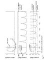
- FIGS. 5 to 7 illustrate exemplary sequences of a shutdown and a subsequent restart of a single cylinder.
- the three diagrams each show from top to bottom
- the inventive method can optionally be applied to several or all the cylinders in an alternating pattern.
- a previously shut down cylinder has to be restarted again and another cylinder will be shut down instead. That way, the risk of the in-cylinder pressure of the first cylinder touching the line of the minimal allowed in-cylinder pressure in Fig. 7 , bottom right corner of the graph, can be substantially reduced.
Landscapes
- Engineering & Computer Science (AREA)
- Mechanical Engineering (AREA)
- General Engineering & Computer Science (AREA)
- Chemical & Material Sciences (AREA)
- Combustion & Propulsion (AREA)
- Output Control And Ontrol Of Special Type Engine (AREA)
Abstract
The inventive adjustment of the exhaust valve opening prior to the shutdown of a selected cylinder of a multi-cylinder internal combustion engine allows controlling the amount of exhaust gas to remain in the cylinder. The mass of exhaust gas left in the cylinder is large enough on the one hand, such that the pressure in the cylinder does not undercut the pressure level where the valves unintentionally open due to gas forces but also small enough on the other hand, such that the maximum allowed in-cylinder pressure is not exceeded.
Description
- The invention relates to a method for shutting down and restarting individual cylinders of a multi-cylinder internal combustion engine.
- Upcoming tight emission legislation force R&D activities to be directed to the development of emission reduction technologies and methods for different types of combustion engines.
- Supercharged Diesel engines tend to emit less NOx emissions at high engine load than at part load, in particular Diesel engines equipped with emission reduction technology e.g. such as Miller cycle and variable valve timing, variable compression ratio, variable inlet receiver temperature and others. Furthermore, engines running with HFO (heavy fuel operation) have more wear and tear and cause increased service effort when running mainly at part load. Thus, a benefit arises from maintaining the full load combustion and emission pattern even at lower engine loads. Cylinder shutdown is a known method. If possible, cylinder shutdown should be realized by leaving inlet and outlet valves closed and turning off the fuel injection of the shutdown cylinder and redirecting the respective amount of fuel to the active cylinders. When doing so, the diesel engine's turbocharger operation remains unchanged, otherwise the matching of the turbocharger to the engine has to be checked and adapted if needed. When leaving the valves of the shutdown cylinder(s) closed, the gas forces on the valve(s) can be large enough to unintentionally open the valve(s) against the spring forces.
- Torque control of port-injected gas engines is realized by controlling the receiver pressure using certain control organs and by adjusting the amount of injected fuel gas. Typically, organs controlling the receiver pressure cause losses which grow with the extent of torque reduction. Running a reduced number of cylinders at high load and shutdown of the others allows for control organ settings with reduced losses. For port-injected engines, cylinders could be shut down without closing the valves by turning off the fuel gas injection and redirecting the respective amount of fuel to the active cylinders (similar as in the case of Diesel engines). However, closing the valves of shut down cylinders and redirecting the respective amount of fuel to the active cylinders allows for unchanged turbocharger operation and for control organ settings with even lower losses. When leaving the valves closed, the gas forces on the valve can be large enough to unintentionally open the valves against the spring forces.
- Torque control of premix gas engines is realized by controlling the receiver pressure using certain control organs. Typically, such control organs cause losses which grow with the extent of torque reduction. Running a reduced number of cylinders at high cylinder-individual load and shut down the others allows for control organ settings with reduced losses. For premix gas engines, at least either inlet or exhaust valves of shut down cylinders have to remain closed; otherwise unburned mixture would escape to the exhaust. The advantage of closing both inlet and exhaust valves of deactivated cylinders is a reduction of gas friction losses. As described above, with closed valve(s) measures have to be taken to avoid unintentional opening. Additionally, measures have to be taken to avoid auto-ignition/knock in the deactivated cylinder(s) of premix gas engines.
- A method for shutting down and restarting individual cylinders of a multi-cylinder internal combustion engine by deactivating the charge change valves and the fuel injection is disclosed in
U.S. Patent No. 5,803,040 , in which the activation or deactivation of the inlet and exhaust valves is controlled time-wise in such fashion that the shutdown of the cylinder takes place after one inlet stroke and the restart of the cylinder takes place before an inlet stroke, thus ensuring that hot exhaust always remains in the shut-down cylinder so that cooling of the combustion chamber is largely prevented. When the cylinder is restarted, this exhaust is first expelled out of the combustion chamber, and only then is a new air/fuel mixture drawn in. - Various other documents, known in the art, disclose variable valve train systems that allow influencing the effective area by reducing one or both of the opening time and the valve lift or even to leave the valves completely closed:
-
U.S. Patent No. 4,050,435 discloses such a system comprising deactivating means between a valve pushrod and its respective valves. -
EP Patent Application No. 0 186 341 discloses another engine valve train system for selectively effecting operation of a pair of side by side valves of a particular cylinder and to effect deactivation of one of the valves in the pair during predetermined modes of engine operation. - In "VCM Valve Control Management - the heart rate reactor", CHTUS-1264-1008-300-EN, the Applicant has disclosed a variable valve train system for large four stroke diesel and gas engines (above 400 kW output) that allows variation of both valve timing and lift, reducing harmful exhaust emissions and allowing engine performance to be adapted to the operating profile of a given engine application.
- It is an object of the present invention to improve a method for shutting down and restarting individual cylinders of a multi-cylinder internal combustion engine by avoiding unintentional opening of the inlet and outlet valves and/ or auto-ignition/knock in the shutdown cylinders of the combustion engine.
- This object is achieved by the method according to the invention, in which, when an individual cylinder is shut down, a time sequence for activation or deactivation of inlet and exhaust valves is controlled such that a shutdown of said selected cylinder takes place after an inlet stroke, the succeeding combustion process and the succeeding exhaust stroke, whereas the exhaust valve opening in this last exhaust stroke prior to the shutdown of said selected cylinder is adjusted to retain a partial amount of the exhaust gas in the cylinder.
- The inventive adjustment of the exhaust valve opening prior to the shutdown of said cylinder allows controlling the amount of exhaust gas to remain in the cylinder. The mass of exhaust gas is to be large enough on the one hand, such that the pressure in the cylinder does not undercut the pressure level where the valves unintentionally open due to gas forces but also small enough on the other hand, such that the maximum allowed in-cylinder pressure is not exceeded.
- Restarting of said selected cylinder takes place after a last skipped combustion by returning to the nominal exhaust valve lift and a succeeding nominal inlet valve lift according to the operation of the selected cylinder.
- With the present invention the shutdown cylinders contain mainly air and burnt gas only which prohibits auto-ignition/knock.
-
-
Fig. 1 shows a prior art variable valve train system, -
Fig. 2 illustrates the inventive method for shutting down and restarting an individual cylinder in a schematic diagram of the valve lift curves of the inlet and exhaust valves of a cylinder and the pressure curve of the pressure in the cylinder before, during and after a cylinder shutdown, -
Fig. 3 shows a schematic diagram of the valve lift curve of a charge change valve with limited valve lift versus full lift, -
Fig. 4 shows a schematic diagram of the valve lift curve of a charge change valve with a reduced opening time (early closing) versus full lift, -
Fig. 5 illustrates the pressure-changes in a cylinder during an exemplary shotdown sequence, -
Fig. 6 illustrates the pressure-changes in a cylinder during an exemplary restart sequence, and -
Fig. 7 illustrates the pressure-changes in a cylinder during an exemplary shotdown sequence with a heat loss to the cylinder wall. -
Fig. 1 shows a variable valve train system of the kind disclosed by the Applicant in the above mentioned publication. Variation in valve timing and lift is achieved by interposing a highpressure fluid chamber 2 into the engine valve train between the valve and its mechanical actuation system. Thechamber 2 filled with fluid is pressurized by a camshaft actuatedpump 1. A piston driven by the fluid pressure inchamber 2 and the valve spring forces actuates the inlet or exhaust valve(s), respectively. Avalve 4 varies the filling and the pressure of thechamber 2 and the loading of the pressure accumulator 5. Controlling the opening and the closing of thevalve 4 enables both the timing of the opening and the closing of the valve irrespective of the camshaft position as well as the distance the valve opens (valve lift).Figs. 3 and 4 show schematically two possibilities to reduce the effective area of a full valve lift (thin line) by either limiting the valve lift (thick line inFig. 3 ) or by an early closing of the valve (thick line inFig. 4 ). Of course, timing of the opening and closing of the valves as well as valve lift can be combined to achieve reduced effective areas. - The variable valve train systems described are only possible embodiments. Of course, other devices can be used. The critical aspect however is that control allows to set different valve timings or valve lifts on a cycle-to-cycle and cylinder-to-cylinder individual basis as well as a precise adjustment of the trapped mass in the cylinder.
-
FIG. 2 shows the valve lift curves of the inlet valve and the exhaust valve for a single cylinder as an example, shown schematically before, during, and after a cylinder shutdown when the method according to the invention is implemented. - During a normal operating cycle of a cylinder of the internal combustion engine, that is when the cylinder is not shut down, both inlet valve and exhaust valve opens according to a nominal pattern assigned to the operation of that cylinder. The crankshaft ranges in which the cylinder shutdown process is not yet activated is labeled (A) in the diagram at the upper left corner. The nominal pattern depicted serves as an example and might vary between different engine types or versions.
- Once a shut down time sequence is initiated by the combustion engines control unit, the normal operating cycle is followed through the combustion process, leaving the full amount of exhaust gas in the cylinder to be shut down. In the very next step of the inventive method, a partial amount of this exhaust gas is removed from the cylinder by a limited opening of the exhaust valve, indicated in the diagram with the reduced lift curve at label (B). In particular, the exhaust valve opening duration or valve lift in step (B) is adjusted, limiting the blow out of exhaust gas to the exhaust gas receiver. The remaining mass of exhaust gas in the cylinder is large enough such that the pressure in the cylinder does not undercut the pressure level where the valves unintentionally open due to gas forces and small enough that the maximum allowed in-cylinder pressure is not exceeded. As a consequence, the maximum pressure in the cylinder for the following cycles is reduced and the risk of unintentional opening of the valves is avoided while all the advantages of keeping - at least a partial amount of - the exhaust gas in the cylinder are maintained.
- The following cycles in the diagram are processed without opening any inlet or exhaust valves. Any number of operating cycles can take place between the cylinder being shut down and its restart, therefore the angle axis is interrupted and the diagram split in an upper (shutdown) and a lower (restart) section
- Once the re-activation time sequence is initiated by the combustion engines control unit, the re-activation of the cylinder is commenced after a final skipped inlet stroke and a final skipped combustion. First, the exhaust valve opens according to its nominal pattern at label (E) to remove the remaining exhaust gas from the cylinder, followed by a nominal pattern of inlet valve at label (F) to fill the cylinder with fresh air or a fresh air / fuel gas mixture, depending on the combustion engine type. During the following high pressure cycle, the first combustion after the shutdown is initiated.
-
Figures 5 to 7 illustrate exemplary sequences of a shutdown and a subsequent restart of a single cylinder. The three diagrams each show from top to bottom - the relative valve lift over time,
- the in-cylinder pressure in relation to the maximal allowed in-cylinder pressure over time, and
- the in-cylinder pressure in relation to the minimal allowed in-cylinder pressure, compared to the air receiver and the exhaust receiver pressure over time.
- In order to avoid significant heat loss to the cylinder wall in a single cylinder of a multi-cylinder engine, the inventive method can optionally be applied to several or all the cylinders in an alternating pattern. In this case, a previously shut down cylinder has to be restarted again and another cylinder will be shut down instead. That way, the risk of the in-cylinder pressure of the first cylinder touching the line of the minimal allowed in-cylinder pressure in
Fig. 7 , bottom right corner of the graph, can be substantially reduced.
Claims (5)
- Method for shutting down and starting of individual cylinders of a multi-cylinder internal combustion engine having at least one inlet valve and at least one exhaust valve per cylinder, with said valves of a selected individual cylinder being deactivated or re-activated during a shutdown or restart of said selected cylinder by means of a suitable device, whereas
when said selected cylinder is switched, a time sequence for deactivation or re-activation of inlet and exhaust valves is controlled such that a shutdown of said selected cylinder takes place after an inlet cycle (1), the succeeding combustion process and the succeeding exhaust stroke (2), whereas the exhaust valve opening in this last exhaust stroke prior to the shutdown of said selected cylinder is adjusted to retain a partial amount of the exhaust gas in the cylinder, and a restart of said selected cylinder takes place before one exhaust stroke (5) and after a next preceding inlet stroke thereof. - Method of Claim 1, whereas the adjustment of the exhaust valve opening is done by limiting the degree of opening of the exhaust valve.
- Method of any of Claims 1 or 2, whereas the adjustment of the exhaust valve opening is done by reducing the duration of opening of the exhaust valve.
- Method of Claim 1, whereas the adjustment of the exhaust valve opening is done by a combination of reducing the duration of opening of the exhaust valve and limiting the degree of opening.
- Method for running a multi-cylinder combustion engine having at least one inlet valve and at least one exhaust valve per cylinder, in which method cylinders of said engine are shut down and restarted in an alternating pattern to avoid undercutting of the minimum allowable in-cylinder pressure due heat transfer to the cylinder wall.
Priority Applications (1)
| Application Number | Priority Date | Filing Date | Title |
|---|---|---|---|
| EP12170541.2A EP2669495A1 (en) | 2012-06-01 | 2012-06-01 | Method for operating a multi-cylinder internal combustion engine |
Applications Claiming Priority (1)
| Application Number | Priority Date | Filing Date | Title |
|---|---|---|---|
| EP12170541.2A EP2669495A1 (en) | 2012-06-01 | 2012-06-01 | Method for operating a multi-cylinder internal combustion engine |
Publications (1)
| Publication Number | Publication Date |
|---|---|
| EP2669495A1 true EP2669495A1 (en) | 2013-12-04 |
Family
ID=46197107
Family Applications (1)
| Application Number | Title | Priority Date | Filing Date |
|---|---|---|---|
| EP12170541.2A Withdrawn EP2669495A1 (en) | 2012-06-01 | 2012-06-01 | Method for operating a multi-cylinder internal combustion engine |
Country Status (1)
| Country | Link |
|---|---|
| EP (1) | EP2669495A1 (en) |
Cited By (10)
| Publication number | Priority date | Publication date | Assignee | Title |
|---|---|---|---|---|
| DE102014206305A1 (en) | 2014-04-02 | 2015-10-08 | Schaeffler Technologies AG & Co. KG | Internal combustion engine with alternating cylinder deactivation |
| DE102014206307A1 (en) | 2014-04-02 | 2015-10-08 | Schaeffler Technologies AG & Co. KG | Internal combustion engine with alternating cylinder deactivation |
| US20150322869A1 (en) * | 2014-05-12 | 2015-11-12 | Tula Technology, Inc. | Internal combustion engine using variable valve lift and skip fire control |
| US9689327B2 (en) | 2008-07-11 | 2017-06-27 | Tula Technology, Inc. | Multi-level skip fire |
| US9689328B2 (en) | 2014-11-10 | 2017-06-27 | Tula Technology, Inc. | Multi-level skip fire |
| CN109026407A (en) * | 2014-11-10 | 2018-12-18 | 图拉技术公司 | Run the method and engine controller of internal combustion engine |
| US10400691B2 (en) | 2013-10-09 | 2019-09-03 | Tula Technology, Inc. | Noise/vibration reduction control |
| US10493836B2 (en) | 2018-02-12 | 2019-12-03 | Tula Technology, Inc. | Noise/vibration control using variable spring absorber |
| US10662883B2 (en) | 2014-05-12 | 2020-05-26 | Tula Technology, Inc. | Internal combustion engine air charge control |
| US11236689B2 (en) | 2014-03-13 | 2022-02-01 | Tula Technology, Inc. | Skip fire valve control |
Citations (5)
| Publication number | Priority date | Publication date | Assignee | Title |
|---|---|---|---|---|
| US4050435A (en) | 1975-12-02 | 1977-09-27 | Harold L. Fuller, Jr. | Valve control for cylinder cutout system |
| EP0186341A1 (en) | 1984-12-24 | 1986-07-02 | General Motors Corporation | Engine valve train system |
| US5803040A (en) | 1995-12-13 | 1998-09-08 | Mercedes Benz Ag | Method for shutting down and restarting individual cylinders of an engine |
| GB2409000A (en) * | 2003-12-12 | 2005-06-15 | Ford Global Tech Llc | I.c. engine cylinder deactivation system |
| US7143727B1 (en) * | 2005-10-05 | 2006-12-05 | Ford Global Technologies, Llc | Exhaust reductant generation in a direct injection engine with cylinder deactivation |
-
2012
- 2012-06-01 EP EP12170541.2A patent/EP2669495A1/en not_active Withdrawn
Patent Citations (5)
| Publication number | Priority date | Publication date | Assignee | Title |
|---|---|---|---|---|
| US4050435A (en) | 1975-12-02 | 1977-09-27 | Harold L. Fuller, Jr. | Valve control for cylinder cutout system |
| EP0186341A1 (en) | 1984-12-24 | 1986-07-02 | General Motors Corporation | Engine valve train system |
| US5803040A (en) | 1995-12-13 | 1998-09-08 | Mercedes Benz Ag | Method for shutting down and restarting individual cylinders of an engine |
| GB2409000A (en) * | 2003-12-12 | 2005-06-15 | Ford Global Tech Llc | I.c. engine cylinder deactivation system |
| US7143727B1 (en) * | 2005-10-05 | 2006-12-05 | Ford Global Technologies, Llc | Exhaust reductant generation in a direct injection engine with cylinder deactivation |
Cited By (18)
| Publication number | Priority date | Publication date | Assignee | Title |
|---|---|---|---|---|
| US9689327B2 (en) | 2008-07-11 | 2017-06-27 | Tula Technology, Inc. | Multi-level skip fire |
| US10634076B2 (en) | 2013-10-09 | 2020-04-28 | Tula Technology, Inc. | Noise/vibration reduction control |
| US10400691B2 (en) | 2013-10-09 | 2019-09-03 | Tula Technology, Inc. | Noise/vibration reduction control |
| US11236689B2 (en) | 2014-03-13 | 2022-02-01 | Tula Technology, Inc. | Skip fire valve control |
| DE102014206305A1 (en) | 2014-04-02 | 2015-10-08 | Schaeffler Technologies AG & Co. KG | Internal combustion engine with alternating cylinder deactivation |
| DE102014206307A1 (en) | 2014-04-02 | 2015-10-08 | Schaeffler Technologies AG & Co. KG | Internal combustion engine with alternating cylinder deactivation |
| WO2015149765A1 (en) | 2014-04-02 | 2015-10-08 | Schaeffler Technologies AG & Co. KG | Internal combustion engine with alternating cylinder shutdown |
| DE102014206305B4 (en) | 2014-04-02 | 2019-12-19 | Schaeffler Technologies AG & Co. KG | Internal combustion engine with alternating cylinder deactivation |
| US10233796B2 (en) * | 2014-05-12 | 2019-03-19 | Tula Technology, Inc. | Internal combustion engine using variable valve lift and skip fire control |
| US10662883B2 (en) | 2014-05-12 | 2020-05-26 | Tula Technology, Inc. | Internal combustion engine air charge control |
| US20150322869A1 (en) * | 2014-05-12 | 2015-11-12 | Tula Technology, Inc. | Internal combustion engine using variable valve lift and skip fire control |
| CN109026407A (en) * | 2014-11-10 | 2018-12-18 | 图拉技术公司 | Run the method and engine controller of internal combustion engine |
| US10072592B2 (en) | 2014-11-10 | 2018-09-11 | Tula Technology, Inc. | Multi-level skip fire |
| US10557427B2 (en) | 2014-11-10 | 2020-02-11 | Tula Technology, Inc. | Multi-level firing engine control |
| US9689328B2 (en) | 2014-11-10 | 2017-06-27 | Tula Technology, Inc. | Multi-level skip fire |
| CN109026407B (en) * | 2014-11-10 | 2020-08-07 | 图拉技术公司 | Method and engine controller for operating an internal combustion engine |
| US10837382B2 (en) | 2014-11-10 | 2020-11-17 | Tula Technology, Inc. | Multi-level firing engine control |
| US10493836B2 (en) | 2018-02-12 | 2019-12-03 | Tula Technology, Inc. | Noise/vibration control using variable spring absorber |
Similar Documents
| Publication | Publication Date | Title |
|---|---|---|
| EP2669495A1 (en) | Method for operating a multi-cylinder internal combustion engine | |
| CN102791998B (en) | For the control system of gasoline engine | |
| KR101908516B1 (en) | Method for shutting off and activating a cylinder of an internal combustion engine | |
| US10161336B2 (en) | System and method for determining valve operation | |
| US6615776B1 (en) | Method of operating a multi-cylinder internal combustion engine | |
| US10634069B2 (en) | Control apparatus for internal combustion engine | |
| US10947917B2 (en) | Methods and system for skip-firing of an engine | |
| RU2697016C2 (en) | Method and system for evaluation of air charge | |
| KR102247397B1 (en) | Internal combustion engine with alternating cylinder shutdown | |
| KR20100106228A (en) | Method for operating an internal combustion engine and the internal combustion engine for carrying out thereof | |
| KR20220030299A (en) | Combined actuation of positive power and cylinder deactivation using a secondary valve event | |
| US11207964B2 (en) | Method for controlling an internal combustion engine | |
| US10655546B2 (en) | Control device for internal combustion engine | |
| JP6019936B2 (en) | Spark ignition direct injection engine | |
| JP6213410B2 (en) | Control device for compression ignition engine | |
| US20110214632A1 (en) | Hydro-mechanical variable valve actuation | |
| KR20170063316A (en) | System and method for control of a transition between si and hcci combustion modes | |
| JP6265082B2 (en) | Control device for compression ignition engine | |
| JP2013253558A (en) | Control device of internal combustion engine | |
| US12378910B1 (en) | Systems and methods for extra-stroke engine cycle operation | |
| US11821379B1 (en) | Non-rotating cylinder pattern selection for equalizing cylinder usage in an internal combustion engine | |
| US7917280B2 (en) | Method and device for operating an internal combustion engine | |
| CN108952975B (en) | Method and device for operating an internal combustion engine of the spark-ignition type | |
| JP2005291161A (en) | Compression ignition internal combustion engine and fuel injection control device thereof | |
| JP5998752B2 (en) | Spark ignition direct injection engine |
Legal Events
| Date | Code | Title | Description |
|---|---|---|---|
| PUAI | Public reference made under article 153(3) epc to a published international application that has entered the european phase |
Free format text: ORIGINAL CODE: 0009012 |
|
| AK | Designated contracting states |
Kind code of ref document: A1 Designated state(s): AL AT BE BG CH CY CZ DE DK EE ES FI FR GB GR HR HU IE IS IT LI LT LU LV MC MK MT NL NO PL PT RO RS SE SI SK SM TR |
|
| AX | Request for extension of the european patent |
Extension state: BA ME |
|
| STAA | Information on the status of an ep patent application or granted ep patent |
Free format text: STATUS: THE APPLICATION IS DEEMED TO BE WITHDRAWN |
|
| 18D | Application deemed to be withdrawn |
Effective date: 20140605 |