EP2669208A1 - A clamp - Google Patents
A clamp Download PDFInfo
- Publication number
- EP2669208A1 EP2669208A1 EP12169683.5A EP12169683A EP2669208A1 EP 2669208 A1 EP2669208 A1 EP 2669208A1 EP 12169683 A EP12169683 A EP 12169683A EP 2669208 A1 EP2669208 A1 EP 2669208A1
- Authority
- EP
- European Patent Office
- Prior art keywords
- leg
- clamp
- plate
- clamp according
- interconnecting
- Prior art date
- Legal status (The legal status is an assumption and is not a legal conclusion. Google has not performed a legal analysis and makes no representation as to the accuracy of the status listed.)
- Granted
Links
- 230000007704 transition Effects 0.000 claims abstract description 19
- 239000000463 material Substances 0.000 claims description 11
- 238000005381 potential energy Methods 0.000 claims description 10
- 229910000639 Spring steel Inorganic materials 0.000 claims description 5
- 239000002184 metal Substances 0.000 claims description 4
- 238000004519 manufacturing process Methods 0.000 description 2
- 230000002349 favourable effect Effects 0.000 description 1
- 238000012986 modification Methods 0.000 description 1
- 230000004048 modification Effects 0.000 description 1
- 238000004806 packaging method and process Methods 0.000 description 1
- 239000011120 plywood Substances 0.000 description 1
Images

Classifications
-
- F—MECHANICAL ENGINEERING; LIGHTING; HEATING; WEAPONS; BLASTING
- F16—ENGINEERING ELEMENTS AND UNITS; GENERAL MEASURES FOR PRODUCING AND MAINTAINING EFFECTIVE FUNCTIONING OF MACHINES OR INSTALLATIONS; THERMAL INSULATION IN GENERAL
- F16B—DEVICES FOR FASTENING OR SECURING CONSTRUCTIONAL ELEMENTS OR MACHINE PARTS TOGETHER, e.g. NAILS, BOLTS, CIRCLIPS, CLAMPS, CLIPS OR WEDGES; JOINTS OR JOINTING
- F16B5/00—Joining sheets or plates, e.g. panels, to one another or to strips or bars parallel to them
- F16B5/06—Joining sheets or plates, e.g. panels, to one another or to strips or bars parallel to them by means of clamps or clips
- F16B5/0607—Joining sheets or plates, e.g. panels, to one another or to strips or bars parallel to them by means of clamps or clips joining sheets or plates to each other
- F16B5/0614—Joining sheets or plates, e.g. panels, to one another or to strips or bars parallel to them by means of clamps or clips joining sheets or plates to each other in angled relationship
-
- B—PERFORMING OPERATIONS; TRANSPORTING
- B65—CONVEYING; PACKING; STORING; HANDLING THIN OR FILAMENTARY MATERIAL
- B65D—CONTAINERS FOR STORAGE OR TRANSPORT OF ARTICLES OR MATERIALS, e.g. BAGS, BARRELS, BOTTLES, BOXES, CANS, CARTONS, CRATES, DRUMS, JARS, TANKS, HOPPERS, FORWARDING CONTAINERS; ACCESSORIES, CLOSURES, OR FITTINGS THEREFOR; PACKAGING ELEMENTS; PACKAGES
- B65D9/00—Containers having bodies formed by interconnecting or uniting two or more rigid, or substantially rigid, components made wholly or mainly of wood or substitutes therefor
- B65D9/12—Containers having bodies formed by interconnecting or uniting two or more rigid, or substantially rigid, components made wholly or mainly of wood or substitutes therefor collapsible, e.g. with all parts detachable
- B65D9/22—Fastening devices for holding collapsible containers in erected state, e.g. integral with container walls
- B65D9/24—Fastening devices for holding collapsible containers in erected state, e.g. integral with container walls separate from container walls
Definitions
- the present invention relates to a clamp for interconnecting two plate-like members so as to make them together form a substantially rectangular corner, said clamp having two legs resiliently connected to each other, making an angle being less than 90° with each other in a rest state of the clamp and being in a state of interconnecting said plate-like members configured to extend around a said corner while storing more potential energy than in said rest state and be located along an outer surface of the plate-like members, each leg having at an outer end thereof remote to a transition to the other leg a member configured to engage a part of a said plate-like member in said interconnecting state.
- Clamps of this type are usually used for interconnecting a number of plate-like members, which may be arranged tightly against each other, for forming a container for packaging purposes.
- said plate-like members are walls, a bottom or a lid of a container.
- a container having a parallelepipedic shape may be obtained. It is conceivable to have all or only some of said plate-like members of a container interconnected by clamps of the type defined above. It is possible to interconnect two such plate-like members by only one clamp or several such clamps.
- Said member of the clamp for engaging a part of a said plate-like member may be of any type, such as male or female and the part to engage of said plate-like member may also be of any type, such as a hole in the plate-like member, a groove therein or a projection formed by an element attached to said plate-like member.
- a clamp of this type is known for example through the Swedish patent 513 684 C2 .
- Clamps of this type are preferably used for creating containers by interconnecting plate-like members therethrough, and when the container has been used for the transport of objects, the clamps may be unlocked and the plate-like members may be separated for getting disposed of or being sent back as a substantially flat package.
- a clamp of this type being easy to handle for interconnecting and disconnecting plate-like members and obtaining a reliable interconnection thereof.
- the object of the present invention is to provide a clamp of the type defined into the introduction enabling a simplified handling thereof in some respect compared to such clamps already known.
- This object is according to the invention obtained by providing a clamp of the type defined in the introduction with the additional features: that at least one of said legs is provided with an opening designed to receive an end of an elongated tool member in said interconnecting state of the clamp for enabling removal of said clamp in said interconnecting state from said plate-like members by influencing that leg in the direction apart from the other leg and by that moving said engagement member out of engagement with said part of the plate-like member.
- the clamp may easily be brought from said interconnecting state to a state for disconnecting from a plate-like member by urging the leg in question apart from the other leg while increasing the potential energy of the clamp by use of a said tool member, such as possibly an ordinary screw driver.
- said opening is directed towards said transition of the legs to each other so as to enable support of said tool member by leg portions in the region of said transition while urging the two legs apart for obtaining said removal. It will thanks to this direction of said opening be possible to rapidly remove said clamp from the interconnecting state without any risk of causing any damage whatsoever on said plate-like member thanks to said support provided for a said tool member.
- the clamp comprises a member defining said opening and extending out from surrounding portions of said leg in the direction towards said transition.
- this member may provide support for an end of a said tool member, so that this may act on said opening defining member without entering into contact with any plate-like member when bringing the clamp out of said interconnecting state, and a further development of this embodiment defines this possibility by the fact that said opening defining member has a surface thereof diverging from said surrounding leg portions and providing support for an end of a said tool member.
- the surface last mentioned of said opening defining member makes an angle with respect to said surrounding leg portions of 5°-30°, 5°-20° or 10°-15°. These are suitable values for a said angle for providing accurate support for a said end of a tool member for removing the clamp from said interconnecting state.
- said opening defining member is formed in one piece with said leg by a portion of leg material bent out from surrounding leg material portions, which results in low manufacturing costs of the clamp and a reliable function thereof.
- said clamp is made of one single flat material piece bent in said transition of one leg to the other, and the clamp is according to another embodiment of the invention made of metal, and in a further preferred embodiment of spring steel.
- Spring steel is a suitable material for this type of clamp, since it provides the resiliency needed and is able to withstand rather tough handling of for instance a container being loaded or unloaded.
- other materials than metal, such as plastic, for the clamp are possible.
- said two legs make an angle of 87°-60°, 85°-60°, 80°-60° or 80°-70° in said rest state of a minimum of potential energy stored.
- Such an angle in said rest state results in a substantial difference in shape of said clamp in the interconnecting state with respect to the rest state and a significantly difference in potential energy stored in the two states for reliably keeping the clamp in said interconnecting state once obtained.
- said engagement member is a male member
- this male member is according to a further development of this embodiment formed by an end of said leg projecting from adjacent leg portions while making an angle of approximately 90°, such as 80°-100°, therewith.
- said opening is located close to said outer end of said leg, such as at a distance thereto being less than 1/3, less than 1/4, less than 1/5 or less than 1/6 of the distance to the transition of that leg to the other leg.
- both legs of the clamp have a said opening, so that the one easiest to reach may be used for disconnecting the clamp from two plate-like members interconnected thereby.
- the invention also relates to a container with at least a bottom and four walls interconnected while together forming substantially rectangular corners of the container, in which at least adjacent walls of said container are interconnected by at least one clamp according to the present invention.
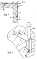
- a clamp 1 according to the present invention for interconnecting two plate-like members so as to make them together form a substantially rectangular corner is illustrated in side-elevation in Fig 1 and in a perspective view in Fig 2 in a rest state of a minimum of potential energy stored therein.
- This clamp is designed to interconnect two plate-like members while forming a container, i.e. a bottom, walls and/or a lid of a container.
- the clamp has two identical legs 2, 3 resiliently connected to each other, which is obtained by manufacturing the clamp of spring steel. Accordingly, a flat spring steel member has been treated to a bent shape for forming said two legs with a transition 4 interconnecting them.
- the two legs make in the rest position of the clamp shown in Fig 1 and 2 an angle ⁇ with respect to each other being less than 90°, here approximately 80°.
- Each leg has at an outer end 5, 6 thereof remote to said transition 4 a member 7, 8 configured to engage a part of a said plate-like member in a state of interconnecting two said plate-like members.
- the engagement members are here of the male type and formed by projections making an angle of approximately 90° with respect to adjacent leg portions 9, 10.
- Each leg is provided with an opening 11, 12 designed to receive an end of an elongated tool member in said interconnecting state of the clamp for enabling removal of said clamp in said interconnecting state from said plate-like members, which will be disclosed further below while making reference to Figs 3 and 4 .
- the opening 11, 12 is defined by a member 13, 14 extending out from surrounding portions of the respective leg in the direction towards the transition 4, and this member is formed in one piece with said leg by a portion of leg material bent out from surrounding leg material portions 9, 10.
- Each such member 13, 14 has a surface 15 diverging from said surrounding leg portions so as to provide support for an end of a said tool member, and this surface makes an angle with respect to said surrounding leg portions of approximately 15° in the embodiment shown.
- the surface is configured to be directed towards the plate-like member this leg bears against in the interconnecting state of the clamp.
- the clamp is brought into a state in which it interconnects two plate-like members 16, 17 so as to make them together form a substantially rectangular corner by introducing the engagement member 7 of one leg 2 into a female member 18, here a groove, in one plate-like member and then urging the other leg 3 apart from the leg 2 while storing potential energy in said clamp and introducing the engagement member 8 of that leg into a female member 19 in the form of a groove in the plate-like member 17. This is easily obtained by pushing the leg 2 close to said transition 4 towards the plate-like member 16.
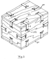
- a bottom 21, four walls 22 and a lid 23 of a container 24 may be hold together by use of clamps 1 according to the invention as illustrated in Fig 3 .
- the container is here made of plywood, but any other suitable material is conceivable, such as metal or plastic.
- a said clamp may be efficiently removed from the interlocking state shown in Fig 3 and Fig 5 without any risk of negative influence upon any plate-like member so as to open a container or disassemble a container for sending the plate-like members thereof further as a flat package.
- a tool member 26 such as an ordinary screwdriver
- the end of the tool member will then find support on the surface 15 of the opening defining member 13, 14 in question and thanks to the fact that the opening is directed towards said transition 4 of the legs to each other the tool member may find support by leg portions in the region of the transition 4 while urging the two legs apart for obtaining said removal. This means that it is ensured that the tool member will not act upon any part of the plate-like member in question. It appears that such a removal may be very easy to carry out and obtained in seconds.
- the two legs of the clamp may have different dimensions, and it is possible that only one of them is provided with a said opening.
- Said opening of at least one clamp leg has not to extend through that leg, but it may be formed by a cavity with a bottom made in said leg.
Landscapes
- Engineering & Computer Science (AREA)
- Mechanical Engineering (AREA)
- General Engineering & Computer Science (AREA)
- Life Sciences & Earth Sciences (AREA)
- Wood Science & Technology (AREA)
- Clamps And Clips (AREA)
Abstract
Description
- The present invention relates to a clamp for interconnecting two plate-like members so as to make them together form a substantially rectangular corner, said clamp having two legs resiliently connected to each other, making an angle being less than 90° with each other in a rest state of the clamp and being in a state of interconnecting said plate-like members configured to extend around a said corner while storing more potential energy than in said rest state and be located along an outer surface of the plate-like members, each leg having at an outer end thereof remote to a transition to the other leg a member configured to engage a part of a said plate-like member in said interconnecting state.
- Clamps of this type are usually used for interconnecting a number of plate-like members, which may be arranged tightly against each other, for forming a container for packaging purposes. Thus, in such a case said plate-like members are walls, a bottom or a lid of a container. In the case of interconnecting six such plate-like members to each other a container having a parallelepipedic shape may be obtained. It is conceivable to have all or only some of said plate-like members of a container interconnected by clamps of the type defined above. It is possible to interconnect two such plate-like members by only one clamp or several such clamps. Said member of the clamp for engaging a part of a said plate-like member may be of any type, such as male or female and the part to engage of said plate-like member may also be of any type, such as a hole in the plate-like member, a groove therein or a projection formed by an element attached to said plate-like member.
- A clamp of this type is known for example through the Swedish patent
513 684 C2 - Clamps of this type are preferably used for creating containers by interconnecting plate-like members therethrough, and when the container has been used for the transport of objects, the clamps may be unlocked and the plate-like members may be separated for getting disposed of or being sent back as a substantially flat package. Thus, it is of course desired to have a clamp of this type being easy to handle for interconnecting and disconnecting plate-like members and obtaining a reliable interconnection thereof.
- The object of the present invention is to provide a clamp of the type defined into the introduction enabling a simplified handling thereof in some respect compared to such clamps already known.
- This object is according to the invention obtained by providing a clamp of the type defined in the introduction with the additional features: that at least one of said legs is provided with an opening designed to receive an end of an elongated tool member in said interconnecting state of the clamp for enabling removal of said clamp in said interconnecting state from said plate-like members by influencing that leg in the direction apart from the other leg and by that moving said engagement member out of engagement with said part of the plate-like member.
- Thanks to the arrangement of said opening in at least one leg of the clamp the clamp may easily be brought from said interconnecting state to a state for disconnecting from a plate-like member by urging the leg in question apart from the other leg while increasing the potential energy of the clamp by use of a said tool member, such as possibly an ordinary screw driver. According to an embodiment of the invention said opening is directed towards said transition of the legs to each other so as to enable support of said tool member by leg portions in the region of said transition while urging the two legs apart for obtaining said removal. It will thanks to this direction of said opening be possible to rapidly remove said clamp from the interconnecting state without any risk of causing any damage whatsoever on said plate-like member thanks to said support provided for a said tool member.
- According to another embodiment of the invention the clamp comprises a member defining said opening and extending out from surrounding portions of said leg in the direction towards said transition. This means that this member may provide support for an end of a said tool member, so that this may act on said opening defining member without entering into contact with any plate-like member when bringing the clamp out of said interconnecting state, and a further development of this embodiment defines this possibility by the fact that said opening defining member has a surface thereof diverging from said surrounding leg portions and providing support for an end of a said tool member.
- According to another embodiment of the invention the surface last mentioned of said opening defining member makes an angle with respect to said surrounding leg portions of 5°-30°, 5°-20° or 10°-15°. These are suitable values for a said angle for providing accurate support for a said end of a tool member for removing the clamp from said interconnecting state.
- According to another embodiment of the invention said opening defining member is formed in one piece with said leg by a portion of leg material bent out from surrounding leg material portions, which results in low manufacturing costs of the clamp and a reliable function thereof.
- According to another embodiment of the invention said clamp is made of one single flat material piece bent in said transition of one leg to the other, and the clamp is according to another embodiment of the invention made of metal, and in a further preferred embodiment of spring steel. Spring steel is a suitable material for this type of clamp, since it provides the resiliency needed and is able to withstand rather tough handling of for instance a container being loaded or unloaded. However, other materials than metal, such as plastic, for the clamp are possible.
- According to another embodiment of the invention said two legs make an angle of 87°-60°, 85°-60°, 80°-60° or 80°-70° in said rest state of a minimum of potential energy stored. Such an angle in said rest state results in a substantial difference in shape of said clamp in the interconnecting state with respect to the rest state and a significantly difference in potential energy stored in the two states for reliably keeping the clamp in said interconnecting state once obtained.
- According to another embodiment of the invention said engagement member is a male member, and this male member is according to a further development of this embodiment formed by an end of said leg projecting from adjacent leg portions while making an angle of approximately 90°, such as 80°-100°, therewith. Having an engagement member in the form of a male member at the outer end of each clamp leg makes it possible to omit unnecessary projections on said plate-like members, which instead may be provided with female members in the form of grooves or holes for engagement with said male members.
- According to another embodiment of the invention said opening is located close to said outer end of said leg, such as at a distance thereto being less than 1/3, less than 1/4, less than 1/5 or less than 1/6 of the distance to the transition of that leg to the other leg. Such a location of said opening results in a favourable lever when acting upon the clamp through said opening for removing the clamp from said interconnecting state making such removal easy.
- According to another embodiment of the invention both legs of the clamp have a said opening, so that the one easiest to reach may be used for disconnecting the clamp from two plate-like members interconnected thereby.
- The invention also relates to a container with at least a bottom and four walls interconnected while together forming substantially rectangular corners of the container, in which at least adjacent walls of said container are interconnected by at least one clamp according to the present invention.
- Further advantages as well as advantageous features of the invention will appear from the following description.
- With reference to the appended drawings, below follows a specific description of a clamp according to an embodiment of the invention cited as an example.
- In the drawings:
- Fig 1
- is a side-elevation view of a clamp according to an embodiment of the invention in a rest position of a minimum of potential energy stored thereby,
- Fig 2
- is a perspective view of the clamp shown in
Fig 1 , - Fig 3
- is a cross-section view of the clamp according to
Fig 1 in a state in which it interconnects two plate-like members, - Fig 4
- is a view illustrating how to remove a clamp from the interconnecting state shown in
Fig 3 , and - Fig 5
- is a perspective view of a container having all six delimiting walls interconnected by means of clamps according to the present invention.
- A
clamp 1 according to the present invention for interconnecting two plate-like members so as to make them together form a substantially rectangular corner is illustrated in side-elevation inFig 1 and in a perspective view inFig 2 in a rest state of a minimum of potential energy stored therein. This clamp is designed to interconnect two plate-like members while forming a container, i.e. a bottom, walls and/or a lid of a container. The clamp has twoidentical legs transition 4 interconnecting them. The two legs make in the rest position of the clamp shown inFig 1 and 2 an angle α with respect to each other being less than 90°, here approximately 80°. - Each leg has at an outer end 5, 6 thereof remote to said transition 4 a
member adjacent leg portions - Each leg is provided with an opening 11, 12 designed to receive an end of an elongated tool member in said interconnecting state of the clamp for enabling removal of said clamp in said interconnecting state from said plate-like members, which will be disclosed further below while making reference to
Figs 3 and 4 . The opening 11, 12 is defined by amember transition 4, and this member is formed in one piece with said leg by a portion of leg material bent out from surroundingleg material portions such member surface 15 diverging from said surrounding leg portions so as to provide support for an end of a said tool member, and this surface makes an angle with respect to said surrounding leg portions of approximately 15° in the embodiment shown. Thus, the surface is configured to be directed towards the plate-like member this leg bears against in the interconnecting state of the clamp. - The function of the clamp shown in
Fig 1 and 2 will now be explained while making reference toFigs 3 and 4 . The clamp is brought into a state in which it interconnects two plate-like members engagement member 7 of oneleg 2 into afemale member 18, here a groove, in one plate-like member and then urging theother leg 3 apart from theleg 2 while storing potential energy in said clamp and introducing theengagement member 8 of that leg into afemale member 19 in the form of a groove in the plate-like member 17. This is easily obtained by pushing theleg 2 close to saidtransition 4 towards the plate-like member 16. This means that the clamp has been brought into the interconnecting state shown inFig 3 , in which the clamp extends around a said corner 20 while storing more potential energy than in said rest state and along an outer surface of the plate-like members. Thus, the clamp will efficiently hold the plate-like members together, since the legs will act towards the mutual position thereof shown inFig 1 . - It is shown in
Fig 5 how abottom 21, fourwalls 22 and alid 23 of acontainer 24 may be hold together by use ofclamps 1 according to the invention as illustrated inFig 3 . The container is here made of plywood, but any other suitable material is conceivable, such as metal or plastic. - It is illustrated in
Fig 4 how a said clamp may be efficiently removed from the interlocking state shown inFig 3 andFig 5 without any risk of negative influence upon any plate-like member so as to open a container or disassemble a container for sending the plate-like members thereof further as a flat package. This is obtained by introducing theend 25 of atool member 26, such as an ordinary screwdriver, into one of theopenings engagement member surface 15 of theopening defining member transition 4 of the legs to each other the tool member may find support by leg portions in the region of thetransition 4 while urging the two legs apart for obtaining said removal. This means that it is ensured that the tool member will not act upon any part of the plate-like member in question. It appears that such a removal may be very easy to carry out and obtained in seconds. - The invention is of course not in any way restricted to the embodiment described above, but many possibilities to modifications thereof would be apparent to a person with ordinary skill in the art without departing from the scope of the invention as defined in the appended claims.
- The two legs of the clamp may have different dimensions, and it is possible that only one of them is provided with a said opening.
- It is also possible to have female engage members at the ends of the legs co-operating with male engagement members on plate-like members.
- Said opening of at least one clamp leg has not to extend through that leg, but it may be formed by a cavity with a bottom made in said leg.
Claims (15)
- A clamp (1) for interconnecting two plate-like members (16, 17) so as to make them together form a substantially rectangular corner (20), said clamp having two legs (2, 3) resiliently connected to each other, making an angle being less than 90° with each other in a rest state of the clamp and being in a state of interconnecting said plate-like members configured to extend around a said corner while storing more potential energy than in said rest state and be located along an outer surface of the plate-like members, each leg having at an outer end (5, 6) thereof remote to a transition (4) to the other leg a member (7, 8) configured to engage a part (18, 19) of a said plate-like member in said interconnecting state,
characterized in that at least one of said legs is provided with an opening (11, 12) designed to receive an end of an elongated tool member in said interconnecting state of the clamp for enabling removal of said clamp in said interconnecting state from said plate-like members by influencing that leg in the direction apart from the other leg and by that moving said engagement member (7, 8) out of engagement with said part of the plate-like member. - A clamp according to claim 1, characterized in that said opening (11, 12) is directed towards said transition (4) of the legs (2, 3) to each other so as to enable support of said tool member by leg portions in the region of said transition while urging the two legs apart for obtaining said removal.
- A clamp according to claim 1 or 2, characterized in that it comprises a member (13, 14) defining said opening and extending out from surrounding portions (9, 10) of said leg in the direction towards said transition (4).
- A clamp according to claim 3, characterized in that said opening defining member (13, 14) has a surface (15) thereof diverging from said surrounding leg portions (9, 10) and providing support for an end of a said tool member.
- A clamp according to claim 4, characterized in that said surface (15) of said opening defining member (13, 14) makes an angle with respect to said surrounding leg portions (9, 10) of 5°-30°, 5°-20° or 10°-15°.
- A clamp according to any of claims 3-5, characterized in that said opening defining member (13, 14) is formed in one piece with said leg by a portion of leg material bent out from surrounding leg material portions (9, 10).
- A clamp according to any of the preceding claims, characterized in that said clamp is made of one single flat material piece bent in said transition (4) of one leg to the other.
- A clamp according to any of the preceding claims, characterized in that it is made of metal.
- A clamp according to claim 8, characterized in that is made of spring steel.
- A clamp according to any of the preceding claims, characterized in that said two legs (2, 3) make an angle of 87°-60°, 85°-60°, 80°-60° or 80°-70° in said rest state of a minimum of potential energy stored.
- A clamp according to any of the preceding claims, characterized in that said engagement member (7, 8) is a male member.
- A clamp according to claim 11, characterized in that said male member (7, 8) is formed by an end of said leg (2, 3) projecting from adjacent leg portions (9, 10) while making an angle of approximately 90°, such as 80°-100°, therewith.
- A clamp according to any of the preceding claims, characterized in that said opening (11, 12) is located close to said outer end (5, 6) of said leg, such as at a distance thereto being less than 1/3, less than 1/4, less than 1/5 or less than 1/6 of the distance to the transition (4) of that leg to the other leg.
- A clamp according to any of the preceding claims, characterized in that both legs (2, 3) have a said opening (11, 12).
- A container (24) with at least a bottom (21) and four walls (22) interconnected while together forming substantially rectangular corners of the container, characterized in that at least adjacent walls of said container are interconnected by at least one clamp (1) according to any of claims 1-14.
Priority Applications (4)
| Application Number | Priority Date | Filing Date | Title |
|---|---|---|---|
| EP12169683.5A EP2669208B1 (en) | 2012-05-28 | 2012-05-28 | A clamp |
| ES12169683.5T ES2548172T3 (en) | 2012-05-28 | 2012-05-28 | Gripper |
| US13/902,201 US20130315652A1 (en) | 2012-05-28 | 2013-05-24 | Clamp |
| CN201310201660.1A CN103449024A (en) | 2012-05-28 | 2013-05-27 | A clamp |
Applications Claiming Priority (1)
| Application Number | Priority Date | Filing Date | Title |
|---|---|---|---|
| EP12169683.5A EP2669208B1 (en) | 2012-05-28 | 2012-05-28 | A clamp |
Publications (2)
| Publication Number | Publication Date |
|---|---|
| EP2669208A1 true EP2669208A1 (en) | 2013-12-04 |
| EP2669208B1 EP2669208B1 (en) | 2015-07-29 |
Family
ID=46245463
Family Applications (1)
| Application Number | Title | Priority Date | Filing Date |
|---|---|---|---|
| EP12169683.5A Not-in-force EP2669208B1 (en) | 2012-05-28 | 2012-05-28 | A clamp |
Country Status (4)
| Country | Link |
|---|---|
| US (1) | US20130315652A1 (en) |
| EP (1) | EP2669208B1 (en) |
| CN (1) | CN103449024A (en) |
| ES (1) | ES2548172T3 (en) |
Cited By (1)
| Publication number | Priority date | Publication date | Assignee | Title |
|---|---|---|---|---|
| WO2024033200A1 (en) * | 2022-08-11 | 2024-02-15 | Häfele Berlin Gmbh & Co Kg | Spring clip and assembly having two plates connected to each other by means of the spring clip |
Families Citing this family (6)
| Publication number | Priority date | Publication date | Assignee | Title |
|---|---|---|---|---|
| NL2009159C2 (en) * | 2012-07-09 | 2014-01-13 | Univ Delft Tech | A combination of a connector for glass elements and such glass elements. |
| EP3042089B1 (en) * | 2013-09-06 | 2018-03-07 | Clip-lok international Limited | Clip for a knock-down structure |
| CA2923134C (en) * | 2013-09-06 | 2020-11-10 | Clip-Lok International Limited | Releasable clip for a knock-down structure |
| US9765513B2 (en) * | 2014-12-15 | 2017-09-19 | Certainteed Corporation | System, method and apparatus for corner siding |
| US11731805B2 (en) | 2021-01-22 | 2023-08-22 | PRO blanket bars GmbH | Collapsible containers including attachment brackets |
| US12397986B2 (en) | 2021-01-22 | 2025-08-26 | PRO blanket bars GmbH | Collapsible containers including edge attachment brackets |
Citations (4)
| Publication number | Priority date | Publication date | Assignee | Title |
|---|---|---|---|---|
| US4461395A (en) * | 1981-07-20 | 1984-07-24 | Burnett Robert A | Reusable, modular, knockdown container |
| WO1992021574A1 (en) * | 1991-05-30 | 1992-12-10 | Crocodile Packaging Ltd. | Collapsible packing container |
| GB2257453A (en) * | 1991-01-28 | 1993-01-13 | Lydney Holdings Limited | A clip for holding together panels of a box-like container |
| SE513684C2 (en) | 1998-05-15 | 2000-10-23 | Nefab Ab | connecting terminal |
Family Cites Families (10)
| Publication number | Priority date | Publication date | Assignee | Title |
|---|---|---|---|---|
| US2760674A (en) * | 1953-02-11 | 1956-08-28 | Majestic Creations Inc | Hollow plastic container |
| GB941178A (en) * | 1958-10-21 | 1963-11-06 | Henry George Kewley | Improvements in frame structures and the joining of members |
| US3345715A (en) * | 1965-08-31 | 1967-10-10 | Lambert Frame And Picture Comp | Clamps for picture frames |
| US3999236A (en) * | 1976-02-26 | 1976-12-28 | Interchange Lighting Corporation | Waterbed frame |
| US4083464A (en) * | 1976-08-20 | 1978-04-11 | Burnett Robert A | Knockdown reusable container |
| US4453471A (en) * | 1981-06-04 | 1984-06-12 | Hb Clip-Lok Industries Ltd. | Panel retaining clamp for collapsible pallet containers |
| US6253507B1 (en) * | 1999-01-20 | 2001-07-03 | Mdf, Inc. | Clip for a door frame system |
| ES1066288Y (en) * | 2007-09-13 | 2008-04-01 | Encaja Embalajes De Madera S L | MOUNTING, REMOVABLE AND REUTLIZABLE BOX |
| DE102010011072B4 (en) * | 2010-03-11 | 2011-12-15 | Fairfix E. K. | Box clamp, transport box, method for assembling a transport box, use of a box clamp for guiding a strapping band |
| US8708178B2 (en) * | 2011-07-26 | 2014-04-29 | Diversified Fixtures, Inc. | Container system and method |
-
2012
- 2012-05-28 ES ES12169683.5T patent/ES2548172T3/en active Active
- 2012-05-28 EP EP12169683.5A patent/EP2669208B1/en not_active Not-in-force
-
2013
- 2013-05-24 US US13/902,201 patent/US20130315652A1/en not_active Abandoned
- 2013-05-27 CN CN201310201660.1A patent/CN103449024A/en active Pending
Patent Citations (4)
| Publication number | Priority date | Publication date | Assignee | Title |
|---|---|---|---|---|
| US4461395A (en) * | 1981-07-20 | 1984-07-24 | Burnett Robert A | Reusable, modular, knockdown container |
| GB2257453A (en) * | 1991-01-28 | 1993-01-13 | Lydney Holdings Limited | A clip for holding together panels of a box-like container |
| WO1992021574A1 (en) * | 1991-05-30 | 1992-12-10 | Crocodile Packaging Ltd. | Collapsible packing container |
| SE513684C2 (en) | 1998-05-15 | 2000-10-23 | Nefab Ab | connecting terminal |
Cited By (1)
| Publication number | Priority date | Publication date | Assignee | Title |
|---|---|---|---|---|
| WO2024033200A1 (en) * | 2022-08-11 | 2024-02-15 | Häfele Berlin Gmbh & Co Kg | Spring clip and assembly having two plates connected to each other by means of the spring clip |
Also Published As
| Publication number | Publication date |
|---|---|
| ES2548172T3 (en) | 2015-10-14 |
| CN103449024A (en) | 2013-12-18 |
| US20130315652A1 (en) | 2013-11-28 |
| EP2669208B1 (en) | 2015-07-29 |
Similar Documents
| Publication | Publication Date | Title |
|---|---|---|
| EP2669208A1 (en) | A clamp | |
| USD1101525S1 (en) | Extractor socket | |
| USD798024S1 (en) | Nestable pallet | |
| EP3166757B1 (en) | Inserts for an assortment box | |
| CN103803156B (en) | Device for orienting a stack of containers | |
| CN107848664A (en) | Article box | |
| USD729488S1 (en) | Pallet | |
| USD833149S1 (en) | Storage container lid | |
| USD774907S1 (en) | Cat food container lid | |
| CA167318S (en) | Case for electronic device | |
| US20150076149A1 (en) | Packaging sleeve with latching cap | |
| USD894700S1 (en) | Open handle ratchet | |
| CA2929748A1 (en) | Container for stackable pallettes equipped with an upper reinforcing frame | |
| EP1810931B1 (en) | A clamp and a container | |
| JP6535155B2 (en) | Shipping container | |
| US9902053B2 (en) | Knockout removal tool | |
| KR101487734B1 (en) | assembly for furniture | |
| US20150068944A1 (en) | Container | |
| JP6249694B2 (en) | Parts removal jig | |
| JP5778604B2 (en) | Box container | |
| KR200484858Y1 (en) | Multi-connectable container | |
| KR200471497Y1 (en) | Many purposes box | |
| KR101596426B1 (en) | Connectable to each other parts deposit boxes | |
| JP6290051B2 (en) | palette | |
| KR101480664B1 (en) | L-sleeve for assembling type unit box and assembling unit box with the same |
Legal Events
| Date | Code | Title | Description |
|---|---|---|---|
| PUAI | Public reference made under article 153(3) epc to a published international application that has entered the european phase |
Free format text: ORIGINAL CODE: 0009012 |
|
| AK | Designated contracting states |
Kind code of ref document: A1 Designated state(s): AL AT BE BG CH CY CZ DE DK EE ES FI FR GB GR HR HU IE IS IT LI LT LU LV MC MK MT NL NO PL PT RO RS SE SI SK SM TR |
|
| AX | Request for extension of the european patent |
Extension state: BA ME |
|
| 17P | Request for examination filed |
Effective date: 20140521 |
|
| RBV | Designated contracting states (corrected) |
Designated state(s): AL AT BE BG CH CY CZ DE DK EE ES FI FR GB GR HR HU IE IS IT LI LT LU LV MC MK MT NL NO PL PT RO RS SE SI SK SM TR |
|
| 17Q | First examination report despatched |
Effective date: 20140619 |
|
| GRAP | Despatch of communication of intention to grant a patent |
Free format text: ORIGINAL CODE: EPIDOSNIGR1 |
|
| INTG | Intention to grant announced |
Effective date: 20150226 |
|
| GRAS | Grant fee paid |
Free format text: ORIGINAL CODE: EPIDOSNIGR3 |
|
| GRAA | (expected) grant |
Free format text: ORIGINAL CODE: 0009210 |
|
| AK | Designated contracting states |
Kind code of ref document: B1 Designated state(s): AL AT BE BG CH CY CZ DE DK EE ES FI FR GB GR HR HU IE IS IT LI LT LU LV MC MK MT NL NO PL PT RO RS SE SI SK SM TR |
|
| REG | Reference to a national code |
Ref country code: GB Ref legal event code: FG4D |
|
| REG | Reference to a national code |
Ref country code: CH Ref legal event code: EP |
|
| REG | Reference to a national code |
Ref country code: AT Ref legal event code: REF Ref document number: 739062 Country of ref document: AT Kind code of ref document: T Effective date: 20150815 |
|
| REG | Reference to a national code |
Ref country code: IE Ref legal event code: FG4D |
|
| REG | Reference to a national code |
Ref country code: DE Ref legal event code: R096 Ref document number: 602012009072 Country of ref document: DE |
|
| REG | Reference to a national code |
Ref country code: ES Ref legal event code: FG2A Ref document number: 2548172 Country of ref document: ES Kind code of ref document: T3 Effective date: 20151014 |
|
| REG | Reference to a national code |
Ref country code: SE Ref legal event code: TRGR |
|
| REG | Reference to a national code |
Ref country code: AT Ref legal event code: MK05 Ref document number: 739062 Country of ref document: AT Kind code of ref document: T Effective date: 20150729 |
|
| REG | Reference to a national code |
Ref country code: LT Ref legal event code: MG4D |
|
| REG | Reference to a national code |
Ref country code: NL Ref legal event code: MP Effective date: 20150729 |
|
| PG25 | Lapsed in a contracting state [announced via postgrant information from national office to epo] |
Ref country code: NO Free format text: LAPSE BECAUSE OF FAILURE TO SUBMIT A TRANSLATION OF THE DESCRIPTION OR TO PAY THE FEE WITHIN THE PRESCRIBED TIME-LIMIT Effective date: 20151029 Ref country code: GR Free format text: LAPSE BECAUSE OF FAILURE TO SUBMIT A TRANSLATION OF THE DESCRIPTION OR TO PAY THE FEE WITHIN THE PRESCRIBED TIME-LIMIT Effective date: 20151030 Ref country code: LV Free format text: LAPSE BECAUSE OF FAILURE TO SUBMIT A TRANSLATION OF THE DESCRIPTION OR TO PAY THE FEE WITHIN THE PRESCRIBED TIME-LIMIT Effective date: 20150729 Ref country code: FI Free format text: LAPSE BECAUSE OF FAILURE TO SUBMIT A TRANSLATION OF THE DESCRIPTION OR TO PAY THE FEE WITHIN THE PRESCRIBED TIME-LIMIT Effective date: 20150729 Ref country code: LT Free format text: LAPSE BECAUSE OF FAILURE TO SUBMIT A TRANSLATION OF THE DESCRIPTION OR TO PAY THE FEE WITHIN THE PRESCRIBED TIME-LIMIT Effective date: 20150729 |
|
| PG25 | Lapsed in a contracting state [announced via postgrant information from national office to epo] |
Ref country code: HR Free format text: LAPSE BECAUSE OF FAILURE TO SUBMIT A TRANSLATION OF THE DESCRIPTION OR TO PAY THE FEE WITHIN THE PRESCRIBED TIME-LIMIT Effective date: 20150729 Ref country code: RS Free format text: LAPSE BECAUSE OF FAILURE TO SUBMIT A TRANSLATION OF THE DESCRIPTION OR TO PAY THE FEE WITHIN THE PRESCRIBED TIME-LIMIT Effective date: 20150729 Ref country code: PL Free format text: LAPSE BECAUSE OF FAILURE TO SUBMIT A TRANSLATION OF THE DESCRIPTION OR TO PAY THE FEE WITHIN THE PRESCRIBED TIME-LIMIT Effective date: 20150729 Ref country code: PT Free format text: LAPSE BECAUSE OF FAILURE TO SUBMIT A TRANSLATION OF THE DESCRIPTION OR TO PAY THE FEE WITHIN THE PRESCRIBED TIME-LIMIT Effective date: 20151130 Ref country code: IS Free format text: LAPSE BECAUSE OF FAILURE TO SUBMIT A TRANSLATION OF THE DESCRIPTION OR TO PAY THE FEE WITHIN THE PRESCRIBED TIME-LIMIT Effective date: 20151129 Ref country code: AT Free format text: LAPSE BECAUSE OF FAILURE TO SUBMIT A TRANSLATION OF THE DESCRIPTION OR TO PAY THE FEE WITHIN THE PRESCRIBED TIME-LIMIT Effective date: 20150729 |
|
| PG25 | Lapsed in a contracting state [announced via postgrant information from national office to epo] |
Ref country code: NL Free format text: LAPSE BECAUSE OF FAILURE TO SUBMIT A TRANSLATION OF THE DESCRIPTION OR TO PAY THE FEE WITHIN THE PRESCRIBED TIME-LIMIT Effective date: 20150729 |
|
| PG25 | Lapsed in a contracting state [announced via postgrant information from national office to epo] |
Ref country code: DK Free format text: LAPSE BECAUSE OF FAILURE TO SUBMIT A TRANSLATION OF THE DESCRIPTION OR TO PAY THE FEE WITHIN THE PRESCRIBED TIME-LIMIT Effective date: 20150729 Ref country code: SK Free format text: LAPSE BECAUSE OF FAILURE TO SUBMIT A TRANSLATION OF THE DESCRIPTION OR TO PAY THE FEE WITHIN THE PRESCRIBED TIME-LIMIT Effective date: 20150729 Ref country code: EE Free format text: LAPSE BECAUSE OF FAILURE TO SUBMIT A TRANSLATION OF THE DESCRIPTION OR TO PAY THE FEE WITHIN THE PRESCRIBED TIME-LIMIT Effective date: 20150729 Ref country code: CZ Free format text: LAPSE BECAUSE OF FAILURE TO SUBMIT A TRANSLATION OF THE DESCRIPTION OR TO PAY THE FEE WITHIN THE PRESCRIBED TIME-LIMIT Effective date: 20150729 |
|
| REG | Reference to a national code |
Ref country code: DE Ref legal event code: R097 Ref document number: 602012009072 Country of ref document: DE |
|
| REG | Reference to a national code |
Ref country code: FR Ref legal event code: PLFP Year of fee payment: 5 |
|
| PG25 | Lapsed in a contracting state [announced via postgrant information from national office to epo] |
Ref country code: RO Free format text: LAPSE BECAUSE OF FAILURE TO SUBMIT A TRANSLATION OF THE DESCRIPTION OR TO PAY THE FEE WITHIN THE PRESCRIBED TIME-LIMIT Effective date: 20150729 |
|
| PLBE | No opposition filed within time limit |
Free format text: ORIGINAL CODE: 0009261 |
|
| STAA | Information on the status of an ep patent application or granted ep patent |
Free format text: STATUS: NO OPPOSITION FILED WITHIN TIME LIMIT |
|
| 26N | No opposition filed |
Effective date: 20160502 |
|
| PG25 | Lapsed in a contracting state [announced via postgrant information from national office to epo] |
Ref country code: BE Free format text: LAPSE BECAUSE OF NON-PAYMENT OF DUE FEES Effective date: 20160531 Ref country code: SI Free format text: LAPSE BECAUSE OF FAILURE TO SUBMIT A TRANSLATION OF THE DESCRIPTION OR TO PAY THE FEE WITHIN THE PRESCRIBED TIME-LIMIT Effective date: 20150729 |
|
| PG25 | Lapsed in a contracting state [announced via postgrant information from national office to epo] |
Ref country code: BE Free format text: LAPSE BECAUSE OF FAILURE TO SUBMIT A TRANSLATION OF THE DESCRIPTION OR TO PAY THE FEE WITHIN THE PRESCRIBED TIME-LIMIT Effective date: 20150729 Ref country code: LU Free format text: LAPSE BECAUSE OF FAILURE TO SUBMIT A TRANSLATION OF THE DESCRIPTION OR TO PAY THE FEE WITHIN THE PRESCRIBED TIME-LIMIT Effective date: 20160528 |
|
| REG | Reference to a national code |
Ref country code: CH Ref legal event code: PL |
|
| PG25 | Lapsed in a contracting state [announced via postgrant information from national office to epo] |
Ref country code: CH Free format text: LAPSE BECAUSE OF NON-PAYMENT OF DUE FEES Effective date: 20160531 Ref country code: LI Free format text: LAPSE BECAUSE OF NON-PAYMENT OF DUE FEES Effective date: 20160531 |
|
| REG | Reference to a national code |
Ref country code: IE Ref legal event code: MM4A |
|
| REG | Reference to a national code |
Ref country code: FR Ref legal event code: PLFP Year of fee payment: 6 |
|
| PG25 | Lapsed in a contracting state [announced via postgrant information from national office to epo] |
Ref country code: IE Free format text: LAPSE BECAUSE OF NON-PAYMENT OF DUE FEES Effective date: 20160528 |
|
| PGFP | Annual fee paid to national office [announced via postgrant information from national office to epo] |
Ref country code: FR Payment date: 20170515 Year of fee payment: 6 Ref country code: GB Payment date: 20170518 Year of fee payment: 6 Ref country code: DE Payment date: 20170517 Year of fee payment: 6 |
|
| PGFP | Annual fee paid to national office [announced via postgrant information from national office to epo] |
Ref country code: SE Payment date: 20170516 Year of fee payment: 6 Ref country code: ES Payment date: 20170602 Year of fee payment: 6 Ref country code: IT Payment date: 20170522 Year of fee payment: 6 |
|
| PG25 | Lapsed in a contracting state [announced via postgrant information from national office to epo] |
Ref country code: HU Free format text: LAPSE BECAUSE OF FAILURE TO SUBMIT A TRANSLATION OF THE DESCRIPTION OR TO PAY THE FEE WITHIN THE PRESCRIBED TIME-LIMIT; INVALID AB INITIO Effective date: 20120528 Ref country code: SM Free format text: LAPSE BECAUSE OF FAILURE TO SUBMIT A TRANSLATION OF THE DESCRIPTION OR TO PAY THE FEE WITHIN THE PRESCRIBED TIME-LIMIT Effective date: 20150729 Ref country code: CY Free format text: LAPSE BECAUSE OF FAILURE TO SUBMIT A TRANSLATION OF THE DESCRIPTION OR TO PAY THE FEE WITHIN THE PRESCRIBED TIME-LIMIT Effective date: 20150729 |
|
| PG25 | Lapsed in a contracting state [announced via postgrant information from national office to epo] |
Ref country code: MT Free format text: LAPSE BECAUSE OF NON-PAYMENT OF DUE FEES Effective date: 20160531 Ref country code: MK Free format text: LAPSE BECAUSE OF FAILURE TO SUBMIT A TRANSLATION OF THE DESCRIPTION OR TO PAY THE FEE WITHIN THE PRESCRIBED TIME-LIMIT Effective date: 20150729 Ref country code: MC Free format text: LAPSE BECAUSE OF FAILURE TO SUBMIT A TRANSLATION OF THE DESCRIPTION OR TO PAY THE FEE WITHIN THE PRESCRIBED TIME-LIMIT Effective date: 20150729 Ref country code: TR Free format text: LAPSE BECAUSE OF FAILURE TO SUBMIT A TRANSLATION OF THE DESCRIPTION OR TO PAY THE FEE WITHIN THE PRESCRIBED TIME-LIMIT Effective date: 20150729 |
|
| PG25 | Lapsed in a contracting state [announced via postgrant information from national office to epo] |
Ref country code: BG Free format text: LAPSE BECAUSE OF FAILURE TO SUBMIT A TRANSLATION OF THE DESCRIPTION OR TO PAY THE FEE WITHIN THE PRESCRIBED TIME-LIMIT Effective date: 20150729 |
|
| PG25 | Lapsed in a contracting state [announced via postgrant information from national office to epo] |
Ref country code: AL Free format text: LAPSE BECAUSE OF FAILURE TO SUBMIT A TRANSLATION OF THE DESCRIPTION OR TO PAY THE FEE WITHIN THE PRESCRIBED TIME-LIMIT Effective date: 20150729 |
|
| REG | Reference to a national code |
Ref country code: DE Ref legal event code: R119 Ref document number: 602012009072 Country of ref document: DE |
|
| REG | Reference to a national code |
Ref country code: SE Ref legal event code: EUG |
|
| GBPC | Gb: european patent ceased through non-payment of renewal fee |
Effective date: 20180528 |
|
| PG25 | Lapsed in a contracting state [announced via postgrant information from national office to epo] |
Ref country code: SE Free format text: LAPSE BECAUSE OF NON-PAYMENT OF DUE FEES Effective date: 20180529 |
|
| PG25 | Lapsed in a contracting state [announced via postgrant information from national office to epo] |
Ref country code: FR Free format text: LAPSE BECAUSE OF NON-PAYMENT OF DUE FEES Effective date: 20180531 Ref country code: DE Free format text: LAPSE BECAUSE OF NON-PAYMENT OF DUE FEES Effective date: 20181201 Ref country code: IT Free format text: LAPSE BECAUSE OF NON-PAYMENT OF DUE FEES Effective date: 20180528 Ref country code: GB Free format text: LAPSE BECAUSE OF NON-PAYMENT OF DUE FEES Effective date: 20180528 |
|
| REG | Reference to a national code |
Ref country code: ES Ref legal event code: FD2A Effective date: 20190913 |
|
| PG25 | Lapsed in a contracting state [announced via postgrant information from national office to epo] |
Ref country code: ES Free format text: LAPSE BECAUSE OF NON-PAYMENT OF DUE FEES Effective date: 20180529 |