EP2668974A2 - Mobile safety anchoring device - Google Patents
Mobile safety anchoring device Download PDFInfo
- Publication number
- EP2668974A2 EP2668974A2 EP13168910.1A EP13168910A EP2668974A2 EP 2668974 A2 EP2668974 A2 EP 2668974A2 EP 13168910 A EP13168910 A EP 13168910A EP 2668974 A2 EP2668974 A2 EP 2668974A2
- Authority
- EP
- European Patent Office
- Prior art keywords
- ring member
- anchoring device
- surrounding wall
- mobile safety
- vertical extension
- Prior art date
- Legal status (The legal status is an assumption and is not a legal conclusion. Google has not performed a legal analysis and makes no representation as to the accuracy of the status listed.)
- Withdrawn
Links
Images


Classifications
-
- A—HUMAN NECESSITIES
- A62—LIFE-SAVING; FIRE-FIGHTING
- A62B—DEVICES, APPARATUS OR METHODS FOR LIFE-SAVING
- A62B1/00—Devices for lowering persons from buildings or the like
- A62B1/06—Devices for lowering persons from buildings or the like by making use of rope-lowering devices
- A62B1/14—Devices for lowering persons from buildings or the like by making use of rope-lowering devices with brakes sliding on the rope
-
- A—HUMAN NECESSITIES
- A62—LIFE-SAVING; FIRE-FIGHTING
- A62B—DEVICES, APPARATUS OR METHODS FOR LIFE-SAVING
- A62B35/00—Safety belts or body harnesses; Similar equipment for limiting displacement of the human body, especially in case of sudden changes of motion
- A62B35/0043—Lifelines, lanyards, and anchors therefore
- A62B35/0068—Anchors
-
- F—MECHANICAL ENGINEERING; LIGHTING; HEATING; WEAPONS; BLASTING
- F16—ENGINEERING ELEMENTS AND UNITS; GENERAL MEASURES FOR PRODUCING AND MAINTAINING EFFECTIVE FUNCTIONING OF MACHINES OR INSTALLATIONS; THERMAL INSULATION IN GENERAL
- F16M—FRAMES, CASINGS OR BEDS OF ENGINES, MACHINES OR APPARATUS, NOT SPECIFIC TO ENGINES, MACHINES OR APPARATUS PROVIDED FOR ELSEWHERE; STANDS; SUPPORTS
- F16M13/00—Other supports for positioning apparatus or articles; Means for steadying hand-held apparatus or articles
- F16M13/02—Other supports for positioning apparatus or articles; Means for steadying hand-held apparatus or articles for supporting on, or attaching to, an object, e.g. tree, gate, window-frame, cycle
Definitions
- the invention relates to an anchoring device, more particularly to a mobile safety anchoring device adapted for securing a vertically extending member such as a lifeline.
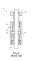
- a conventional mobile safety anchoring device 1 disclosed in US Patent No. 3335469 and including a housing 11, a cone-shaped member 12 that is disposed in an end of the housing 11, a slider 13 that extends through the cone-shaped member 12, and a plurality of steel balls 14 that are received in the slider 13 and disposed adjacent to the cone-shaped member 12.
- the steel balls 14 will be pressured by the cone-shaped member 12 to move inwardly to press against and secure a rope 15 that extends through the slider 13, such that the conventional mobile safety anchoring device 1 can no longer move in relation to the cord 15.
- the slider 13 is downwardly pushed in relation to the main body 11, simultaneously moving the steel balls 14 downward until the cord 15 is released from being pressed against by the steel balls 14. At this time, the conventional mobile safety anchoring device 1 can slide along the cord 15 for position adjustment.
- FIG. 2 Shown in Fig. 2 is another conventional mobile safety anchoring device 2 disclosed in Japanese Patent Application Publication No. H10-184814 and including a housing 21 that has an inner coned surface 211, an inner sleeve member 22 disposed in the housing 21, a cover body 23 threadedly engaged to the inner sleeve member 22, and a plurality of spheres 24 received in the inner sleeve member 22.
- the conventional mobile safety anchoring device 2 functions similarly to the conventional mobile safety anchoring device 1, where the inner coned surface 211 is used to push the spheres 24 to press against a cord 25 that passes through the inner sleeve member 22, and where when the cover body 23 is pressed to move the inner sleeve member 22downwardly relative to the housing 21, the spheres 24 will be released from being pushed by the inner coned surface 211 and allow positioning adjustments of the conventional mobile safety anchoring device 2 along the cord 25.
- neither the slider 13 nor the inner sleeve member 22 may be secured so that the steel balls 14 and the spheres 24 may be released from clamping the rope 15 and the cord 25, leading to safety concerns.
- the spheres 24 will be at asymmetric positions relative to the inner coned surface 211, forming gaps therebetween, and making the clamping of the conventional mobile safety anchoring device 2 on the cord 25 unstable.
- the object of the present invention is to provide a mobile safety anchoring device that can eliminate the aforesaid drawbacks of the prior art.
- a mobile safety anchoring device adapted to be slidably sleeved around a vertical extension member.
- the mobile safety anchoring device includes an outer ring member, an inner ringmember, a plurality of positioning members, a resilient component and a limiting member.
- the outer ring member is adapted for surrounding the vertical extension member and includes an outer surrounding wall that defines an accommodating space.
- the outer surrounding wall has a top end and a bottom end that is opposite to the top end.
- An inner surface of the outer surrounding wall has a first converging portion that converges from the bottom end toward the top end.
- the inner ring member is adapted for surrounding the vertical extension member and is slidably and partially received in the accommodating space of the outer ring member.
- the inner ring member includes an inner surrounding wall that defines a passage for extension of the vertical extension member therethrough.
- the inner surrounding wall has a protruding portion that protrudes outwardly of the accommodating space, and a plurality of positioning holes that are disposed within the accommodating space.
- the positioning members are respectively disposed in the positioning holes in the inner ring member and between the first converging portion of the inner surface of the outer ring member and the vertical extension member.
- the resilient component abuts against the inner surrounding wall of the inner ring member for generating a biasing force that moves the inner ring member in relation to the outer ring member in a way that the positioning members are moved toward the first converging portion and forced by the first converging portion to abut against the vertical extension member, thereby positioning the mobile safety anchoring device on the vertical extension member.
- the limiting member is connected to the protruding portion of the inner ring member, and is operable to move relative to the inner ring member between a locked position and an unlocked position.
- the locked position the limiting member abuts against the outer ring member and prevents movement of the inner ring member relative to the outer ring member against the biasing force generated by the resilient component.
- the unlocked position the limiting member forms a gap with the outer ring member and is operable to bring the inner ring member to move relative to the outer ring member to overcome the biasing force of the resilient component such that the positioning members are no longer forced by the first converging portion of the outer ring member to abut against the vertical extension member to permit the mobile safety anchoring device to slide along the vertical extension member.
- a mobile safety anchoring device 3 is adapted to be slidably sleeved on a vertical extension member 91.
- the vertical extension member 91 may be a rod or a rope such as a lifeline and is not limited thereto.
- the mobile safety anchoring device 3 includes an outer ring member 4, an inner ring member 5, a plurality of positioning members 6, a plurality of resilient components 52 and a limiting member 7.
- the outer ring member 4 is adapted for surrounding the vertical extension member 91 and includes an outer surrounding wall 41 and a blocking wall 42.
- the outer surrounding wall 41 defines an accommodating space 415 and has a top end 411 and a bottom end 412 that is opposite to the top end 411.
- An inner surface of the outer surrounding wall 41 has spaced-apart first and second converging portions 413, 414 each converging from the bottom end 412 toward the top end 411.
- the blocking wall 42 is secured to the bottom end 412 of the outer surrounding wall 41.
- the inner ring member 5 is adapted for surrounding the vertical extension member 91 and is slidably and partially received in the accommodating space 415 of the outer ring member 4.
- the inner ring member 5 includes an inner surrounding wall 51 that defines a passage 511 for extension of the vertical extension member 91 therethrough.
- the inner surrounding wall 51 has a protruding portion 512 that protrudes outwardly of the accommodating space 415, and a plurality of positioning holes 513 that are disposed within the accommodating space 415.
- the positioning members 6 are each disposed in a respective one of the positioning holes 513 in the inner ring member 5 and between the vertical extension member 91 and a corresponding one of the first and second converging portions 413, 414 of the inner surface of the outer ring member 4.
- each of the positioning members 6 is a sphere.
- each of the resilient components 52 abut against and between the inner surrounding wall 51 of the inner ring member 5 and the blocking wall 42 of the outer ring member 4 for generating a biasing force that moves the inner ring member 5 in relation to the outer ring member 4, such that the positioning members 6 are moved respectively toward the first and second converging portions 413, 414 and are forced by the first and second converging portions 413, 414 to abut against the vertical extension member 91, thereby positioning the mobile safety anchoring device 3 on the vertical extension member 91.
- the positioning holes 513 in the inner ring member 5 are respectively aligned with the first and second converging portions 413, 414 when the biasing force generated by the resilient components 52 is not overcome.
- each of the resilient components 52 is a compression spring. It should be noted herein that this invention is not to be limited to the number of the resilient components 52.
- the limiting member 7 is connected to the protruding portion 512 of the inner ring member 5 and is operable to move relative to the inner ring member 5 between a locked position and an unlocked position.
- the limiting member 7 forms a gap (G) with the outer ring member 4, and is operable to bring the inner ring member 5 to move relative to the outer ring member 4 to overcome the biasing force of the resilient components 52 such that the positioning members 6 are not forced by the corresponding first and second converging portions 413, 414 of the outer ring member 4 to abut against the vertical extension member 91 to thereby permit the mobile safety anchoring device 3 to slide along the vertical extension member 91.
- the limiting member 7 when in the locked position, the limiting member 7 abuts against the outer ring member 4 and prevents movement of the inner ring member 5 relative to the outer ring member 4 against the biasing force generated by the resilient components 52.
- the mobile safety anchoring device 3 of this embodiment further includes a fixing ring 81 that is sleeved around the top end 411 of the outer surrounding wall 41 of the outer ring member 4 and the limiting member 7, and that includes an inner flange 811.
- the inner flange 811 abuts against the limiting member 7 when the limiting member 7 is in the unlocked position.
- the mobile safety anchoring device 3 further includes a packing ring 82 that is sleeved around the bottom end 412 of the outer surrounding wall 41 of the outer ring member 4 and that is spaced apart from the fixing ring 81.
- each of the outer surrounding wall 41 of the outer ring member 4 and the protruding portion 512 of the inner ring member 5 has an outer thread 416, 514.
- Each of the fixing ring 81 and the packing ring 82 has an inner thread 812, 821, that engages threadedly the outer thread 416 for securing the corresponding one of the fixing ring 81 and the packing ring 82 to the outer surrounding wall 41.
- the limiting member 7 has an inner thread 71 that engages threadedly and movably the outer thread 514 of the inner ring member 5 so that the limiting member 7 is movable between the locked position and the unlocked position.
- the manner of engagement of these components is not to be limited to the above.
- the resilient components 52 push the inner surrounding wall 51 of the inner ring member 5 in an upward direction from the bottom end 412 of the outer surrounding wall 41 toward the top end 411 of the outer surrounding wall 41 so that the positioning members 6 are pressed inwardly by the corresponding first and second converging portions 413, 414 to abut against the vertical extension member 91to position the mobile safety anchoring device 3 on the vertical extension member 91.
- the limiting member 7 is pressed relative to the outer ring member 4 to bring the inner ring member 5 to move toward the bottom end 412 of the outer surrounding wall 41 against the biasing force of the resilient components 52, until the positioning members 6 are no longer pressured by the corresponding first and second converging portions 413, 414 against the vertical extension member 91.
- the limiting member 7 may then be released to allow for the biasing force of the resilient members 52 to take effect again, pushing the inner ring member 5 to the position shown in Fig. 4 , and making the positioning members 6 cooperatively clamp on the vertical extension member 91 .
- the limiting member 7 is to be rotated threadedly to the locked position, i.e., until the limiting member 7 abuts against the top end 411 of the outer surrounding wall 41, such that the inner ring member 5 is unable to move in a downward direction from the top end 411 toward the bottom end 412 against the biasing force of the resilient members 52, and therefore incapable of releasing the clamping force of the positioning members 6 against the vertical extension member 91 to thereby maintain securely the mobile safety anchoring device 3 on the vertical extension member 91, and prevent accidental movement of the inner ring member 5.
- the limiting member 7 is rotated threadedly and upwardly to reach the position in Fig. 4 , where the inner flange 811 of the fixing ring 81 abuts against the limiting member 7 to prevent complete disengagement of the limiting member 7 from the inner ring member 5.
- multiple mobile safety anchoring devices 3 may be used together with a plurality of vertical extension members 91respectively extending therethrough. Once the mobile safety anchoring devices 3 are locked at desired locations on the respective vertical extension members 91 using the limiting members
- a plate 92 can be placed among the mobile safety anchoring devices 3 and clampedbetween the fixing ring 81 and the packing ring 82 of each mobile safety anchoring device 3.
- the plate 92 can be used for displaying decorations, or for storage purposes.
- the use of additional positioning members 6 is permitted to increase the clamping force on the vertical extension member 91.
- the clamping force on the vertical extension member 9 by the positioning members 6 is further enhanced with reduced gaps between the inner ring member 5 and the vertical extension member 91, permitting plates 92 of various lengths and weights or having uneven loads placed thereon to be securely fixed between the fixing ring 81 and packing ring 82.
- the mobile safety anchoring device 3 when the limiting member 7 is in the unlocked position, the mobile safety anchoring device 3 is permitted to slide along the vertical extension member 91 so as to be placed at any desirable position. Subsequently, by moving the limiting member 7 to the locked position, the mobile safety anchoring device 3 will securely clamp on the vertical extension member 91 such that inadvertent actions will not result in loosening of the mobile safety anchoring device 3 from the vertical extension member 91, thereby elevating safety of use.
Landscapes
- Health & Medical Sciences (AREA)
- General Health & Medical Sciences (AREA)
- Business, Economics & Management (AREA)
- Emergency Management (AREA)
- Engineering & Computer Science (AREA)
- General Engineering & Computer Science (AREA)
- Mechanical Engineering (AREA)
- Clamps And Clips (AREA)
- Telephone Set Structure (AREA)
- Mechanical Control Devices (AREA)
Abstract
Description
- The invention relates to an anchoring device, more particularly to a mobile safety anchoring device adapted for securing a vertically extending member such as a lifeline.
- Shown in
Fig. 1 is a conventional mobilesafety anchoring device 1 disclosed inUS Patent No. 3335469 and including ahousing 11, a cone-shaped member 12 that is disposed in an end of thehousing 11, aslider 13 that extends through the cone-shaped member 12, and a plurality ofsteel balls 14 that are received in theslider 13 and disposed adjacent to the cone-shaped member 12. When thehousing 11 is downwardly pulled in relation to theslider 13, thesteel balls 14 will be pressured by the cone-shaped member 12 to move inwardly to press against and secure arope 15 that extends through theslider 13, such that the conventional mobilesafety anchoring device 1 can no longer move in relation to thecord 15. To release the conventional mobilesafety anchoring device 1 from this securing state, theslider 13 is downwardly pushed in relation to themain body 11, simultaneously moving thesteel balls 14 downward until thecord 15 is released from being pressed against by thesteel balls 14. At this time, the conventional mobilesafety anchoring device 1 can slide along thecord 15 for position adjustment. - Shown in
Fig. 2 is another conventional mobilesafety anchoring device 2 disclosed in Japanese Patent Application Publication No.H10-184814 housing 21 that has an innerconed surface 211, aninner sleeve member 22 disposed in thehousing 21, acover body 23 threadedly engaged to theinner sleeve member 22, and a plurality ofspheres 24 received in theinner sleeve member 22. The conventional mobilesafety anchoring device 2 functions similarly to the conventional mobilesafety anchoring device 1, where the innerconed surface 211 is used to push thespheres 24 to press against acord 25 that passes through theinner sleeve member 22, and where when thecover body 23 is pressed to move the inner sleeve member 22downwardly relative to thehousing 21, thespheres 24 will be released from being pushed by the innerconed surface 211 and allow positioning adjustments of the conventional mobilesafety anchoring device 2 along thecord 25. - For both of the aforementioned cases, neither the
slider 13 nor theinner sleeve member 22 may be secured so that thesteel balls 14 and thespheres 24 may be released from clamping therope 15 and thecord 25, leading to safety concerns. In addition, taking the conventional mobilesafety anchoring device 2 for illustration, when the same is subjected to an oblique force, thespheres 24 will be at asymmetric positions relative to the innerconed surface 211, forming gaps therebetween, and making the clamping of the conventional mobilesafety anchoring device 2 on thecord 25 unstable. - Therefore, the object of the present invention is to provide a mobile safety anchoring device that can eliminate the aforesaid drawbacks of the prior art.
- According to the present invention, there is provided a mobile safety anchoring device adapted to be slidably sleeved around a vertical extension member. The mobile safety anchoring device includes an outer ring member, an inner ringmember, a plurality of positioning members, a resilient component and a limiting member.
- The outer ring member is adapted for surrounding the vertical extension member and includes an outer surrounding wall that defines an accommodating space. The outer surrounding wall has a top end and a bottom end that is opposite to the top end. An inner surface of the outer surrounding wall has a first converging portion that converges from the bottom end toward the top end.
- The inner ring member is adapted for surrounding the vertical extension member and is slidably and partially received in the accommodating space of the outer ring member. The inner ring member includes an inner surrounding wall that defines a passage for extension of the vertical extension member therethrough. The inner surrounding wall has a protruding portion that protrudes outwardly of the accommodating space, and a plurality of positioning holes that are disposed within the accommodating space.
- The positioning members are respectively disposed in the positioning holes in the inner ring member and between the first converging portion of the inner surface of the outer ring member and the vertical extension member.
- The resilient component abuts against the inner surrounding wall of the inner ring member for generating a biasing force that moves the inner ring member in relation to the outer ring member in a way that the positioning members are moved toward the first converging portion and forced by the first converging portion to abut against the vertical extension member, thereby positioning the mobile safety anchoring device on the vertical extension member.
- The limiting member is connected to the protruding portion of the inner ring member, and is operable to move relative to the inner ring member between a locked position and an unlocked position. When in the locked position, the limiting member abuts against the outer ring member and prevents movement of the inner ring member relative to the outer ring member against the biasing force generated by the resilient component. When in the unlocked position, the limiting member forms a gap with the outer ring member and is operable to bring the inner ring member to move relative to the outer ring member to overcome the biasing force of the resilient component such that the positioning members are no longer forced by the first converging portion of the outer ring member to abut against the vertical extension member to permit the mobile safety anchoring device to slide along the vertical extension member.
- Other features and advantages of the present invention will become apparent in the following detailed description of the preferred embodiment with reference to the accompanying drawings, of which:
-
Fig. 1 is a sectional view of a conventional mobile safety anchoring device; -
Fig. 2 is a sectional view of another conventional mobile safety anchoring device; -
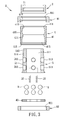
Fig. 3 is an exploded sectional view of the preferred embodiment of the mobile safety anchoring device according to the present invention; -
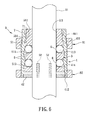
Fig. 4 is an assembled sectional view of the preferred embodiment for illustrating a limiting member in an unlocked position and an inner ring member biased by a plurality of resilient members to move upward; -
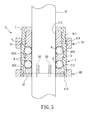
Fig. 5 is an assembled sectional view of the preferred embodiment for illustrating the limiting member in the unlocked position and the limiting member being pressed by a user to bring the inner ring member to overcome a biasing force generated by the resilient members; -
Fig. 6 is an assembled sectional view of the preferred embodiment for illustrating the limiting member in a locked position; and -
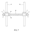
Fig. 7 is a partly sectional schematic view of an assembly of a plurality of the preferred embodiments interconnected by a plate. - Referring to
Fig. 3 and4 , the preferred embodiment of a mobilesafety anchoring device 3 according to the present invention is adapted to be slidably sleeved on avertical extension member 91. Thevertical extension member 91 may be a rod or a rope such as a lifeline and is not limited thereto. - The mobile
safety anchoring device 3 includes anouter ring member 4, aninner ring member 5, a plurality of positioningmembers 6, a plurality ofresilient components 52 and a limitingmember 7. - The
outer ring member 4 is adapted for surrounding thevertical extension member 91 and includes an outer surroundingwall 41 and ablocking wall 42. The outer surroundingwall 41 defines anaccommodating space 415 and has atop end 411 and abottom end 412 that is opposite to thetop end 411. An inner surface of the outer surroundingwall 41 has spaced-apart first and second convergingportions bottom end 412 toward thetop end 411. The blockingwall 42 is secured to thebottom end 412 of the outer surroundingwall 41. - The
inner ring member 5 is adapted for surrounding thevertical extension member 91 and is slidably and partially received in theaccommodating space 415 of theouter ring member 4. Theinner ring member 5 includes an inner surroundingwall 51 that defines apassage 511 for extension of thevertical extension member 91 therethrough. The inner surroundingwall 51 has aprotruding portion 512 that protrudes outwardly of theaccommodating space 415, and a plurality ofpositioning holes 513 that are disposed within theaccommodating space 415. - The
positioning members 6 are each disposed in a respective one of thepositioning holes 513 in theinner ring member 5 and between thevertical extension member 91 and a corresponding one of the first andsecond converging portions outer ring member 4. In this embodiment, each of thepositioning members 6 is a sphere. - The
resilient components 52 abut against and between the inner surroundingwall 51 of theinner ring member 5 and the blockingwall 42 of theouter ring member 4 for generating a biasing force that moves theinner ring member 5 in relation to theouter ring member 4, such that thepositioning members 6 are moved respectively toward the first and second convergingportions portions vertical extension member 91, thereby positioning the mobilesafety anchoring device 3 on thevertical extension member 91. Thepositioning holes 513 in theinner ring member 5 are respectively aligned with the first and second convergingportions resilient components 52 is not overcome. In this embodiment, each of theresilient components 52 is a compression spring. It should be noted herein that this invention is not to be limited to the number of theresilient components 52. - The
limiting member 7 is connected to the protrudingportion 512 of theinner ring member 5 and is operable to move relative to theinner ring member 5 between a locked position and an unlocked position. With reference toFigs. 4 and5 , when in the unlocked position, the limitingmember 7 forms a gap (G) with theouter ring member 4, and is operable to bring theinner ring member 5 to move relative to theouter ring member 4 to overcome the biasing force of theresilient components 52 such that thepositioning members 6 are not forced by the corresponding first andsecond converging portions outer ring member 4 to abut against thevertical extension member 91 to thereby permit the mobilesafety anchoring device 3 to slide along thevertical extension member 91. Referring toFig. 6 , when in the locked position, the limitingmember 7 abuts against theouter ring member 4 and prevents movement of theinner ring member 5 relative to theouter ring member 4 against the biasing force generated by theresilient components 52. - Referring back to
Figs. 3 and4 , the mobilesafety anchoring device 3 of this embodiment further includes afixing ring 81 that is sleeved around thetop end 411 of the outer surroundingwall 41 of theouter ring member 4 and thelimiting member 7, and that includes aninner flange 811. Theinner flange 811 abuts against the limitingmember 7 when thelimiting member 7 is in the unlocked position. The mobilesafety anchoring device 3 further includes apacking ring 82 that is sleeved around thebottom end 412 of the outer surroundingwall 41 of theouter ring member 4 and that is spaced apart from thefixing ring 81. - It should be noted that, in this embodiment, each of the outer surrounding
wall 41 of theouter ring member 4 and the protrudingportion 512 of theinner ring member 5 has anouter thread fixing ring 81 and thepacking ring 82 has aninner thread outer thread 416 for securing the corresponding one of thefixing ring 81 and thepacking ring 82 to the outer surroundingwall 41. Thelimiting member 7 has aninner thread 71 that engages threadedly and movably theouter thread 514 of theinner ring member 5 so that thelimiting member 7 is movable between the locked position and the unlocked position. However, the manner of engagement of these components is not to be limited to the above. - With reference to
Fig. 4 , when thelimiting member 7 is in the unlocked position and when no external force is applied to overcome the biasing force generated by theresilient components 52, theresilient components 52 push the inner surroundingwall 51 of theinner ring member 5 in an upward direction from thebottom end 412 of the outer surroundingwall 41 toward thetop end 411 of the outer surroundingwall 41 so that thepositioning members 6 are pressed inwardly by the corresponding first andsecond converging portions safety anchoring device 3 on thevertical extension member 91. - With reference to
Fig. 5 , to re-position the safetymobile anchoring device 3 on thevertical extension member 91, i.e., to permit sliding of the safetymobile anchoring device 3 on thevertical extension member 91, the limitingmember 7 is pressed relative to theouter ring member 4 to bring theinner ring member 5 to move toward thebottom end 412 of the outer surroundingwall 41 against the biasing force of theresilient components 52, until thepositioning members 6 are no longer pressured by the corresponding first andsecond converging portions vertical extension member 91. - After the position of the mobile
safety anchoring device 3 on thevertical extension member 91 is confirmed, thelimiting member 7 may then be released to allow for the biasing force of theresilient members 52 to take effect again, pushing theinner ring member 5 to the position shown inFig. 4 , and making thepositioning members 6 cooperatively clamp on thevertical extension member 91 . Referring toFig. 6 , at this time, thelimiting member 7 is to be rotated threadedly to the locked position, i.e., until thelimiting member 7 abuts against thetop end 411 of the outer surroundingwall 41, such that theinner ring member 5 is unable to move in a downward direction from thetop end 411 toward thebottom end 412 against the biasing force of theresilient members 52, and therefore incapable of releasing the clamping force of the positioningmembers 6 against thevertical extension member 91 to thereby maintain securely the mobilesafety anchoring device 3 on thevertical extension member 91, and prevent accidental movement of theinner ring member 5. Since the limitingmember 7 abuts tightly against thetop end 411 of the outer surroundingwall 41 and since theinner ring member 5 is immovable, an oblique force applied to the mobilesafety anchoring device 3 when the limitingmember 7 is in the locked position will not result in gaps between thepositioning members 6 and the corresponding first andsecond converging portions positioning members 6 to maintain secure grip on the vertical extension member 9. - To move the
limiting member 7 from the locked position to the unlocked position, thelimiting member 7 is rotated threadedly and upwardly to reach the position inFig. 4 , where theinner flange 811 of thefixing ring 81 abuts against the limitingmember 7 to prevent complete disengagement of the limitingmember 7 from theinner ring member 5. - Referring to
Figs. 4 and7 , multiple mobilesafety anchoring devices 3 may be used together with a plurality of vertical extension members 91respectively extending therethrough. Once the mobilesafety anchoring devices 3 are locked at desired locations on the respectivevertical extension members 91 using the limiting members - 7 thereof, a
plate 92 can be placed among the mobilesafety anchoring devices 3 and clampedbetween the fixingring 81 and thepacking ring 82 of each mobilesafety anchoring device 3. As a result, theplate 92 can be used for displaying decorations, or for storage purposes. In this embodiment, since there are two convergingportions outer ring member 4, the use ofadditional positioning members 6 is permitted to increase the clamping force on thevertical extension member 91. In addition, with the fixingring 81 and packingring 82 surrounding theouter ring member 4 and reinforcing structural strength of theouter ring member 4, the clamping force on the vertical extension member 9 by thepositioning members 6 is further enhanced with reduced gaps between theinner ring member 5 and thevertical extension member 91, permittingplates 92 of various lengths and weights or having uneven loads placed thereon to be securely fixed between the fixingring 81 and packingring 82. - In summary, when the limiting
member 7 is in the unlocked position, the mobilesafety anchoring device 3 is permitted to slide along thevertical extension member 91 so as to be placed at any desirable position. Subsequently, by moving the limitingmember 7 to the locked position, the mobilesafety anchoring device 3 will securely clamp on thevertical extension member 91 such that inadvertent actions will not result in loosening of the mobilesafety anchoring device 3 from thevertical extension member 91, thereby elevating safety of use.
Claims (8)
- A mobile safety anchoring device (3) adapted to be slidably sleeved around a vertical extension member (91), said mobile safety anchoring device (3) comprising:an outer ring member (4) adapted for surrounding the vertical extension member (91) and including an outer surrounding wall (41) that defines an accommodating space (415), said outer surrounding wall (41) having a top end (411) and a bottom end (412) that is opposite to said top end (411), an inner surface of said outer surrounding wall (41) having a first converging portion (413) that converges from said bottom end (412) toward said top end (411);an inner ring member (5) adapted for surrounding the vertical extension member (91) and slidably and partially received in said accommodating space (415) of said outer ring member (4), said inner ring member (5) including an inner surrounding wall (51) that def ines a passage (511) for extension of the vertical extension member (91) therethrough, said inner surrounding wall (51) having a protruding portion (512) that protrudes outwardly of said accommodating space (415), and a plurality of positioning holes (513) that are disposed within said accommodating space (415);a plurality of positioning members (6) respectively disposed in said positioning holes (513) in said inner ringmember (5) and between said first converging portion (413) and the vertical extension member (91); anda resilient component (52) abutting against said inner surrounding wall (51) of said inner ring member (5) for generating a biasing force that moves said inner ring member (5) in relation to said outer ring member (4) in a way that said positioning members (6) are moved toward said first converging portion (413) and forced by said first converging portion (413) to abut against theverticalextension member (91), thereby positioning said mobile safety anchoring device (3) on the vertical extension member (91);said mobile safety anchoring device (3) being characterized by a limiting member (7) that is connected to said protruding portion (512) of said inner ring member (5), and that is operable to move relative to said inner ring member (5) between a locked position and an unlocked position;wherein when in the locked position, said limiting member (7) abuts against said outer ring member (4) and prevents movement of said inner ring member (5) relative to said outer ring member (4) against the biasing force generated by said resilient component (52), and when in the unlockedposition, said limiting member (7) forms a gap (G) with said outer ring member (4) and is operable to bring said inner ring member (5) to move relative to said outer ring member (4) to overcome the biasing force of said resilient component (52) such that said positioning members (6) are no longer forced by said first converging portion (413) of said outer ring member (4) to abut against the vertical extension member (91) to permit said mobile safety anchoring device (3) to slide along the vertical extension member (91).
- The mobile safety anchoring device (3) as claimed in Claim 1, further characterized by a fixing ring (81) that is sleeved around said top end (411) of said outer surrounding wall (41) of said outer ring member (4) and said limiting member (7); and
characterized in that said fixing ring (81) includes an inner flange (811) that abuts against said limiting member (7) when said limiting member (7) is in the unlocked position. - The mobile safety anchoring device (3) as claimed in Claim 2, characterized in that the inner surface of said outer surrounding wall (41) further has a second converging portion (414) converging from said bottom end (412) toward said top end (411) and spaced apart from said first converging portion (413), said positioning holes (513) in said inner ring member (5) being respectively aligned with said first and second converging portions (413, 414) when the biasing force generated by said resilient component (52) is not overcome.
- The mobile safety anchoring device (3) as claimed in Claim 3, characterized in that said outer ring member (4) further includes a blocking wall (42) secured to said bottom end (412) of said outer surrounding wall (41), said resilient component (52) abutting against and between said inner surrounding wall (51) of said inner ring member (5) and said blocking wall (42) of said outer ring member (4).
- The mobile safety anchoring device (3) as claimed in any one of Claims 2, 3 and 4, further characterized by a packing ring (82) that is sleeved around and operable to move along said bottom end (412) of said outer surrounding wall (41) of said outer ring member (4) and that is spaced apart from said fixing ring (81).
- The mobile safety anchoring device (3) as claimed in Claim 5, characterized in that said outer surrounding wall (41) of said outer ring member (4) has an outer thread (416), and each of said fixing ring (81) and said packing ring (82) has an inner thread (812, 821) that engages threadedly said outer thread (416) for securing the corresponding one of said fixing ring (81) and said packing ring (82) to said outer surrounding wall (41).
- The mobile safety anchoring device (3) as claimed in Claim 5, characterized in that saidprotrudingportion (512) of said inner surrounding wall (51) of said inner ring member (5) has an outer thread (514), and said limiting member (7) has an inner thread (71) that engages threadedly and movably said outer thread (514) so that said limiting member (7) is movable between the locked position and the unlocked position.
- The mobile safety anchoring device (3) as claimed in Claim 5, characterized in that said resilient component (52) is a compression spring.
Applications Claiming Priority (1)
| Application Number | Priority Date | Filing Date | Title |
|---|---|---|---|
| TW101119139A TW201347805A (en) | 2012-05-29 | 2012-05-29 | Hoist adjusting device |
Publications (2)
| Publication Number | Publication Date |
|---|---|
| EP2668974A2 true EP2668974A2 (en) | 2013-12-04 |
| EP2668974A3 EP2668974A3 (en) | 2015-04-15 |
Family
ID=48537779
Family Applications (1)
| Application Number | Title | Priority Date | Filing Date |
|---|---|---|---|
| EP13168910.1A Withdrawn EP2668974A3 (en) | 2012-05-29 | 2013-05-23 | Mobile safety anchoring device |
Country Status (4)
| Country | Link |
|---|---|
| US (1) | US20130319799A1 (en) |
| EP (1) | EP2668974A3 (en) |
| JP (1) | JP2013245820A (en) |
| TW (1) | TW201347805A (en) |
Cited By (1)
| Publication number | Priority date | Publication date | Assignee | Title |
|---|---|---|---|---|
| GB2588722A (en) * | 2012-12-21 | 2021-05-05 | Electronic Theatre Controls Inc | Compact hoist accessories and combination systems |
Citations (2)
| Publication number | Priority date | Publication date | Assignee | Title |
|---|---|---|---|---|
| US3335469A (en) | 1963-11-19 | 1967-08-15 | Barrow Hepburn & Gale Ltd | Personal safety equipment |
| JPH10184814A (en) | 1996-12-26 | 1998-07-14 | Yasuo Matsuda | Slide clamper |
Family Cites Families (9)
| Publication number | Priority date | Publication date | Assignee | Title |
|---|---|---|---|---|
| JPS5491664A (en) * | 1977-12-29 | 1979-07-20 | Hideo Arakawa | Universal retainer and universal retaining device |
| DE8236311U1 (en) * | 1982-12-24 | 1983-03-03 | Skf Kugellagerfabriken Gmbh, 8720 Schweinfurt | DOUBLE FREEWHEEL FOR LINEAR MOVEMENTS |
| US4893810A (en) * | 1986-07-21 | 1990-01-16 | Lee Scott H | Quick release collar |
| US5141355A (en) * | 1989-03-22 | 1992-08-25 | Star Lock Systems, Inc. | Lock and release apparatus |
| JP2510827Y2 (en) * | 1990-03-20 | 1996-09-18 | 荒川技研工業株式会社 | Wire upholstery |
| CN2874100Y (en) * | 2005-08-05 | 2007-02-28 | 冷鹭浩 | Telescopic lube locking device |
| US8037973B2 (en) * | 2008-06-10 | 2011-10-18 | Ruei-Hsing Lin | Fixing device for anti-slip cable lock |
| TW201135081A (en) * | 2010-04-09 | 2011-10-16 | Ming Ren Hang Co Ltd | Elevation adjustment device |
| CN101839270A (en) * | 2010-05-19 | 2010-09-22 | 名人行有限公司 | Elevating adjusting device |
-
2012
- 2012-05-29 TW TW101119139A patent/TW201347805A/en not_active IP Right Cessation
-
2013
- 2013-05-17 US US13/896,463 patent/US20130319799A1/en not_active Abandoned
- 2013-05-22 JP JP2013107553A patent/JP2013245820A/en active Pending
- 2013-05-23 EP EP13168910.1A patent/EP2668974A3/en not_active Withdrawn
Patent Citations (2)
| Publication number | Priority date | Publication date | Assignee | Title |
|---|---|---|---|---|
| US3335469A (en) | 1963-11-19 | 1967-08-15 | Barrow Hepburn & Gale Ltd | Personal safety equipment |
| JPH10184814A (en) | 1996-12-26 | 1998-07-14 | Yasuo Matsuda | Slide clamper |
Cited By (2)
| Publication number | Priority date | Publication date | Assignee | Title |
|---|---|---|---|---|
| GB2588722A (en) * | 2012-12-21 | 2021-05-05 | Electronic Theatre Controls Inc | Compact hoist accessories and combination systems |
| US11319198B2 (en) | 2012-12-21 | 2022-05-03 | Electronic Theatre Controls, Inc. | Compact hoist accessories and combination systems |
Also Published As
| Publication number | Publication date |
|---|---|
| US20130319799A1 (en) | 2013-12-05 |
| TWI492772B (en) | 2015-07-21 |
| TW201347805A (en) | 2013-12-01 |
| JP2013245820A (en) | 2013-12-09 |
| EP2668974A3 (en) | 2015-04-15 |
Similar Documents
| Publication | Publication Date | Title |
|---|---|---|
| JP5939541B2 (en) | connector | |
| US9193561B2 (en) | Cable management device | |
| TWM449183U (en) | Sheet-to-sheet quick positioning device | |
| KR20090086305A (en) | Extension device and tripod | |
| US20150190938A1 (en) | Knife and sheath assembly with realeasable knife securing function | |
| WO2016091053A1 (en) | Connecting device and display screen having same | |
| US10065058B2 (en) | Tolerance ring in external energy absorber | |
| US9884209B2 (en) | Rope grab | |
| US9518600B2 (en) | Safety hook | |
| JP2009522523A (en) | Fastener | |
| EP2975456A1 (en) | Extending/retracting device | |
| JP2017150498A (en) | Flexible lock unit | |
| KR200469702Y1 (en) | Block support device | |
| EP2668974A2 (en) | Mobile safety anchoring device | |
| CA2933230C (en) | Safety brake for telescopic furniture column | |
| JP3191956U (en) | Hook device | |
| JP3193302U (en) | clothes hanger | |
| CN103375464A (en) | Fastening device | |
| CN202520718U (en) | Fastening device | |
| TWM481571U (en) | Mounting device | |
| KR101354602B1 (en) | Locking device for pipe member | |
| TWM474533U (en) | Connecting devices used for anti-dropping device | |
| TWM473102U (en) | Anti-loose buckling device for tool dropping prevention sling | |
| US10052522B2 (en) | Brake bar | |
| TWI434983B (en) | With the structure of the eagle frame pedal |
Legal Events
| Date | Code | Title | Description |
|---|---|---|---|
| PUAI | Public reference made under article 153(3) epc to a published international application that has entered the european phase |
Free format text: ORIGINAL CODE: 0009012 |
|
| AK | Designated contracting states |
Kind code of ref document: A2 Designated state(s): AL AT BE BG CH CY CZ DE DK EE ES FI FR GB GR HR HU IE IS IT LI LT LU LV MC MK MT NL NO PL PT RO RS SE SI SK SM TR |
|
| PUAL | Search report despatched |
Free format text: ORIGINAL CODE: 0009013 |
|
| AK | Designated contracting states |
Kind code of ref document: A3 Designated state(s): AL AT BE BG CH CY CZ DE DK EE ES FI FR GB GR HR HU IE IS IT LI LT LU LV MC MK MT NL NO PL PT RO RS SE SI SK SM TR |
|
| RIC1 | Information provided on ipc code assigned before grant |
Ipc: A62B 35/00 20060101AFI20150312BHEP |
|
| STAA | Information on the status of an ep patent application or granted ep patent |
Free format text: STATUS: THE APPLICATION IS DEEMED TO BE WITHDRAWN |
|
| 18D | Application deemed to be withdrawn |
Effective date: 20151016 |