EP2668658B1 - Ac power conditioning circuit - Google Patents
Ac power conditioning circuit Download PDFInfo
- Publication number
- EP2668658B1 EP2668658B1 EP11857171.0A EP11857171A EP2668658B1 EP 2668658 B1 EP2668658 B1 EP 2668658B1 EP 11857171 A EP11857171 A EP 11857171A EP 2668658 B1 EP2668658 B1 EP 2668658B1
- Authority
- EP
- European Patent Office
- Prior art keywords
- coil
- lead
- choke
- leg
- accordance
- Prior art date
- Legal status (The legal status is an assumption and is not a legal conclusion. Google has not performed a legal analysis and makes no representation as to the accuracy of the status listed.)
- Active
Links
- 230000003750 conditioning effect Effects 0.000 title description 3
- 239000003990 capacitor Substances 0.000 claims description 29
- 230000008878 coupling Effects 0.000 claims description 6
- 238000010168 coupling process Methods 0.000 claims description 6
- 238000005859 coupling reaction Methods 0.000 claims description 6
- 230000007935 neutral effect Effects 0.000 description 13
- 230000001052 transient effect Effects 0.000 description 13
- 238000010586 diagram Methods 0.000 description 9
- 239000000306 component Substances 0.000 description 8
- 230000001629 suppression Effects 0.000 description 5
- 229910000859 α-Fe Inorganic materials 0.000 description 5
- 230000001939 inductive effect Effects 0.000 description 3
- 238000004804 winding Methods 0.000 description 3
- 230000015572 biosynthetic process Effects 0.000 description 2
- DGLFSNZWRYADFC-UHFFFAOYSA-N chembl2334586 Chemical compound C1CCC2=CN=C(N)N=C2C2=C1NC1=CC=C(C#CC(C)(O)C)C=C12 DGLFSNZWRYADFC-UHFFFAOYSA-N 0.000 description 2
- 230000001143 conditioned effect Effects 0.000 description 2
- 230000035939 shock Effects 0.000 description 2
- RYGMFSIKBFXOCR-UHFFFAOYSA-N Copper Chemical compound [Cu] RYGMFSIKBFXOCR-UHFFFAOYSA-N 0.000 description 1
- 238000013459 approach Methods 0.000 description 1
- 230000008859 change Effects 0.000 description 1
- 239000008358 core component Substances 0.000 description 1
- 238000012937 correction Methods 0.000 description 1
- 238000013461 design Methods 0.000 description 1
- 238000005265 energy consumption Methods 0.000 description 1
- 238000001914 filtration Methods 0.000 description 1
- 239000000463 material Substances 0.000 description 1
- 229910044991 metal oxide Inorganic materials 0.000 description 1
- 150000004706 metal oxides Chemical class 0.000 description 1
- 238000012986 modification Methods 0.000 description 1
- 230000004048 modification Effects 0.000 description 1
- 239000003973 paint Substances 0.000 description 1
- 238000009738 saturating Methods 0.000 description 1
- 238000012360 testing method Methods 0.000 description 1
Images

Classifications
-
- H—ELECTRICITY
- H01—ELECTRIC ELEMENTS
- H01F—MAGNETS; INDUCTANCES; TRANSFORMERS; SELECTION OF MATERIALS FOR THEIR MAGNETIC PROPERTIES
- H01F27/00—Details of transformers or inductances, in general
- H01F27/34—Special means for preventing or reducing unwanted electric or magnetic effects, e.g. no-load losses, reactive currents, harmonics, oscillations, leakage fields
- H01F27/343—Preventing or reducing surge voltages; oscillations
- H01F27/345—Preventing or reducing surge voltages; oscillations using auxiliary conductors
-
- H—ELECTRICITY
- H01—ELECTRIC ELEMENTS
- H01F—MAGNETS; INDUCTANCES; TRANSFORMERS; SELECTION OF MATERIALS FOR THEIR MAGNETIC PROPERTIES
- H01F27/00—Details of transformers or inductances, in general
- H01F27/34—Special means for preventing or reducing unwanted electric or magnetic effects, e.g. no-load losses, reactive currents, harmonics, oscillations, leakage fields
- H01F27/38—Auxiliary core members; Auxiliary coils or windings
-
- H—ELECTRICITY
- H02—GENERATION; CONVERSION OR DISTRIBUTION OF ELECTRIC POWER
- H02H—EMERGENCY PROTECTIVE CIRCUIT ARRANGEMENTS
- H02H9/00—Emergency protective circuit arrangements for limiting excess current or voltage without disconnection
- H02H9/04—Emergency protective circuit arrangements for limiting excess current or voltage without disconnection responsive to excess voltage
-
- Y—GENERAL TAGGING OF NEW TECHNOLOGICAL DEVELOPMENTS; GENERAL TAGGING OF CROSS-SECTIONAL TECHNOLOGIES SPANNING OVER SEVERAL SECTIONS OF THE IPC; TECHNICAL SUBJECTS COVERED BY FORMER USPC CROSS-REFERENCE ART COLLECTIONS [XRACs] AND DIGESTS
- Y02—TECHNOLOGIES OR APPLICATIONS FOR MITIGATION OR ADAPTATION AGAINST CLIMATE CHANGE
- Y02E—REDUCTION OF GREENHOUSE GAS [GHG] EMISSIONS, RELATED TO ENERGY GENERATION, TRANSMISSION OR DISTRIBUTION
- Y02E40/00—Technologies for an efficient electrical power generation, transmission or distribution
- Y02E40/30—Reactive power compensation
Definitions
- the present invention relates to the distribution of AC power, and more particularly to apparatus for conditioning the power delivered and reducing energy usage.
- Transient surges are common on all power systems. Lightning, generator switching, and major power line shorts are examples of externally generated surges. Transients up to twice the applied voltage are common and up to 50 times the applied voltage have been observed.
- transient surges caused by inductive load devices such as motors, transformers, relay coil and fluorescent light ballasts. These are known as internally generated surges.
- US 5,422,620 discloses a transformer with at least three cores separated from one another, each forming a magnetic circuit, a first coil which winds around at least two of that cores, and at least a second coil, at least one of the cores being looped by both the first as well as the second coil, at least one of the cores which are looped by the first coil having an air gap, wherein at least two of the cores enclosed by the first coil have different magnetic characteristics, the resulting magnetic characteristic of these two cores being different from the magnetic characteristic of at least the third core, and wherein the second coil also winds around at least two cores.
- Any load that requires a magnetic field to operate for example motors, transformers, fluorescent lamp ballasts, solenoids, and the like will cause the phase relationship between voltage and current supplied by the utility to change. Such phase shifting reduces the efficiency of the load, resulting in increased power consumption.
- the phase angle between voltage and current is called power factor.
- Inductive circuits have a lagging power factor because the current lags the voltage.
- Capacitive circuits have a leading power factor because the current leads the voltage. It is desirable to make the angle between voltage and current approach zero.
- the power factor is unity and the most efficient utilization of the power distribution system is obtained.
- a multi-coil choke is provided.
- the choke includes a magnetic core having a first leg, a second leg and a third leg. The three legs are substantially parallel to each other.
- a first coil is wrapped around the first leg. The first coil terminates in a first lead at a first end thereof and a second lead at a second end thereof.
- a second coil is wrapped around the second leg of the core and terminates in a first lead at a first end thereof and a second lead at a second end thereof.
- a third coil is wrapped around the third leg and terminates in a first lead at a first end thereof and a second lead at a second end thereof.
- a fourth coil is formed from a proximal portion of the second lead of the first coil. The fourth coil is wrapped around a distal portion of the second lead of the third coil.
- a fifth coil is formed from a proximal portion of the second lead of the third coil. The fifth coil is wrapped around a distal portion of the second lead of the first coil.
- the distal portion of the second lead of said first coil passes through said third coil before passing through said fifth coil.
- the distal portion of the second lead of said third coil passes through said first coil before passing through said fourth coil.
- the magnetic core can be formed from two rectangular closed cores placed side-by-side with adjacent sides forming the second leg.
- the first and third legs can each include a gap.
- the second leg can include substantially aligned gaps in the adjacent sides of the rectangular closed cores. The gaps can be centrally located along their respective legs. An additional gap can be provided along the length of the adjacent sides of the rectangular closed cores.
- each of the rectangular closed cores can be contained within an insulating cover.
- the multi-coil choke in accordance with the invention has its first coil wrapped in one of a clockwise and counterclockwise direction, with the second and third coils being wrapped in the other of the clockwise and counterclockwise direction. More particularly, the first coil can be wrapped in a counterclockwise direction with the second and third coils wrapped in a clockwise direction.
- the fourth coil is wrapped in the same direction as the first coil, e.g., counterclockwise.
- the fifth coil is wrapped in the same direction as the third coil, e.g., clockwise.
- a power conditioner for AC power lines in accordance with a preferred embodiment of the invention includes a multi-coil choke and at least one capacitor. Means are provided for coupling the choke and at least one capacitor in series across an AC power source.
- the power conditioner can have a plurality of the multi-coil chokes, each coupled in series with at least one capacitor across a respective AC power source.
- the coupling means are adapted to couple each of the multi-coil chokes with the first and fourth coils in series with at least one capacitor across a respective AC power source, the second coil in series with at least one capacitor across a respective AC power source, and the third and fifth coils in series with at least one capacitor across a respective AC power source.
- the coupling means can be adapted to couple the first and fourth coils in series with at least one capacitor across a respective AC power source, the second coil in series with at least one capacitor across a respective AC power source; and the third and fifth coils in series with at least one capacitor across a respective AC power source.
- the magnetic core can be formed from two rectangular closed cores placed side-by-side with adjacent sides forming the second leg.
- Each of the first and third legs can include a gap.
- the second leg can include substantially aligned gaps in the adjacent sides of the rectangular closed cores.
- the gaps in the first, second and third legs can be centrally located along their respective legs.
- An additional gap can reside along the length of the adjacent sides of the rectangular closed cores. This additional gap can result, e.g., from the provision of an insulating cover on each of the rectangular closed cores.
- a power conditioner for alternating current in accordance with the invention uses a unique multi-coil choke.
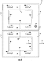
- a magnetic core structure 10 is shown that can be used to fabricate a choke in accordance with the invention.
- the choke can be fabricated, for example, using two side by side cores 12 and 14.
- Such cores can comprise, for example, "Snap-together Torroid Choke” cores available from Radio Shack under Catalog No. 273-104. These cores include a ferrite core with a plastic outer cover.
- cover 13 (shown in a solid line) is illustrated surrounding core sections 12a, 12b (shown in dashed lines) and cover 15 (shown in a solid line) is shown surrounding core sections 14a, 14b (shown in dashed lines).
- Each of the cores 12 and 14 is constructed from two C-shaped ferrite core components 12a, 12b and 14a, 14b respectively that, when assembled side by side within the plastic outer covers 13, 15 respectively, form gaps where the top and bottom ends of each "C" meet. These gaps can be seen at reference numerals 16 and 18a in the core 12. Similar gaps 18b and 22 are shown in the core 14. When the two cores 12 and 14 are placed side by side as shown in Figure 1 , an additional gap 24 is formed along the adjacent sides of the cores. It is noted that the gap 24 comprises the space between the actual ferrite cores (i.e., between the dashed lines) which is mostly dictated by the thickness of the walls of the plastic cover portions 13, 15 that reside within the gap.
- the core structure shown in Figure 1 results in three legs around which wire coils are wound in accordance with the invention. These are a top leg 31, middle leg 33a, 33b and bottom leg 35. As can be seen, the top leg 31 is part of core 12, the bottom leg 35 is part of core 14, and the middle leg 33a, 33b comprises portions of both cores 12 and 14.
- a dot 110 e.g., paint
- the magnetic field created when the choke is energized will be oriented in the directions shown by arrows 100, 102, 104 and 106.
- the field in the first leg 31 will be oriented from left to right as designated by arrows 100.
- the field in the second leg 33a, 33b will be oriented from right to left as designated by arrows 102, 104.
- the field in the third leg 35 will be oriented from left to right as designated by arrows 106.
- the coils can also be wrapped such that the magnetic fields will be oriented in directions opposite to those shown in the example of Figure 1 .
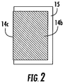
- Figure 2 is a cross section of the core taken along the line 2-2 shown in Figure 1 .
- Figure 2 illustrates the ferrite core 14b inside of plastic cover 15.
- the cover 15 acts as an insulating jacket for the core. It is noted that the cover 15 covers three sides of the core 14b, with the side 14c of the ferrite core being exposed.
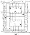
- FIG 3 is an enlarged, detailed view of a choke in accordance with the invention that has been wound on the core structure 10 of Figure 1 .
- the choke has five coils, three of which (first coil 30, second coil 32 and third coil 34) are wound around respective legs 31, 33a,b and 35 of the core.
- a fourth coil 36 is wound around a lead portion of the third coil.
- the fifth coil 38 is wound around a lead portion of the first coil.
- the choke is adapted for use in various embodiments of AC power conditioners, also referred to as "shunt efficiency" systems. Examples of such power conditioners are provided in Figures 4-8 .
- first coil 30 is wrapped around first leg 31 of core 12.
- Second coil 32 is wrapped around a second leg, which consists of leg 33a of core 12 and adjacent leg 33b of core 14.
- Third coil 34 is wrapped around a third leg 35 of core 14.
- the gaps 16 and 22 are centered along first leg 31 and third leg 35, respectively.
- gaps 18a and 18b are generally aligned in a centered position along second leg 33a, 33b.
- the three legs 31, 33a,b and 35 are substantially parallel to each other.
- first, second and third coils are wrapped around their respective legs is important to the operation of the multi-coil choke and, more particularly, to power conditioners fabricated from the choke.
- first coil 30 is wrapped in one direction (e.g., counterclockwise) and the second and third coils 32, 34 are wrapped in the opposite direction (e.g., clockwise). It should be appreciated that these directions can be reversed, as long as the relationships between the coils is maintained.
- each of coils 30, 32 and 34 will have 4-6 turns of, e.g., 12 AWG insulated stranded copper wire.
- each of the first, second and third coils 30, 32 and 34 has five turns, with the first coil wrapped around leg 31 in a counterclockwise direction and the second and third coils wrapped around leg 33a, 33b and 35, respectively, in a clockwise direction.
- fourth and fifth coils 36 and 38, respectively have seven turns.
- Fourth coil 36 extends from the first coil 30 and fifth coil 38 extends from the third coil 34.
- first coil 30 has a first lead 40 and a second lead 41.
- the fourth coil 36 is formed from a portion of second lead 41 that is proximal to first coil 30.
- third coil 34 has a first lead 44 and a second lead 45.
- the fifth coil 38 is formed from a portion of second lead 45 that is proximal to the third coil 34.
- the fourth coil 36 is wrapped around a portion 45' of the second lead 45 of the third coil 34 that is distal to the third coil 34.
- the fifth coil 38 is wrapped around a portion 41' of the second lead 41 of first coil 30 that is distal to the first coil 30.
- the second lead 45 of the third coil passes through the first coil 30 as shown at 45". This occurs after formation of the fifth coil 38 in the second lead 45.
- the distal portion of the second lead 45 of the third coil 34 passes through the first coil 30 before passing through the fourth coil 36.
- the second lead 41 of the first coil passes through the third coil 34 as shown at 41". This occurs after the formation of the fourth coil 36 in the second lead 41 of coil 30. As a result, the distal portion of the second lead 41 of the first coil 30 passes through the third coil 34 before passing through the fifth coil 38.
- the unique choke shown in Figure 3 can be used in any of a variety of different power conditioner implementations. These include, for example, 120/240 volt single phase residential/recreational units, as well as 208, 240, 480 and 600 volt three phase commercial/industrial units (for three, four, and five wire applications). Various such embodiments are shown in Figures 4-8 . It is noted that for clarity in the drawings, the air gaps 16, 18, 22 and 24 of the chokes, which are shown in the enlarged views of Figures 1 and 3 , are not illustrated in Figures 4-8 . However, each of the chokes in Figures 4-8 has these air gaps.
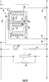
- Figure 4 is a schematic diagram of an example single phase 120 volt power conditioner implementation.
- the first lead 40 of the first coil 30 is connected to the line 50 (L1) of an AC power source to be conditioned.
- the second lead 41 of the first coil 30 is connected at its free end to the neutral 52 (N) of the AC power source via a capacitor 54.
- the first lead 44 of the third coil 34 is connected to the line 50 (L1) of the AC power source, and the second lead 45 is connected at its free end to neutral 52 through a capacitor 56.
- Second coil 32 is coupled between line 50 and neutral 52 as well.
- line 42 of second coil 32 is coupled to line 50 (L1) and line 43 of the second coil 32 is coupled to neutral 52 (N) via capacitor 58.
- a lamp 60 (e.g., LED or incandescent) is connected between line 50 and neutral 52 via a current limiting resistor 62.
- Transient suppression is provided by a varistor (e.g., MOV) 64 coupled between L1 and neutral.
- a bleed resistor 66 is coupled in parallel with varistor 64 to bleed off stored charges, thereby reducing the possibility of electrical shock to an electrician working with the unit after power has been turned off.
- FIG. 5 is a schematic diagram of an example 240 volt recreational unit (e.g., for watercraft) having line 50 (L1), line 53 (L2) and neutral 52 (N).
- a single choke 10 is used with the first, second and third coils 30, 32, 34 coupled as shown. Additional components in this implementation include lamp 61 and series resistor 63, varistor 65 with parallel bleed resistor 67, and varistor 68.
- Figure 6 shows an example 240 volt three phase power conditioner implementation using the multi-coil chokes 10 of the present invention.
- two identical chokes 10a and 10b are used. These chokes are the same as choke 10 illustrated in Figure 3 .
- the first, second and third coils 30, 32 and 34 of each choke are coupled to lines L1, L2 and N of the AC power source as shown. Additional components in this implementation include capacitors 70, 72 and 74.
- Figure 7 shows a three phase embodiment suitable, e.g., for a 480 volt power conditioner installed on an AC source having three hot lines 50 (L1), 53 (L2) and 55 (L3).
- Three chokes 10a, 10b and 10c are provided, each having the same configuration of the choke 10 shown in Figure 3 .
- the first, second and third coils 30, 32 and 34 of each choke are coupled to lines L1, L2 and L3 of the power source as shown.
- Additional components in this implementation include lamp 80 and series resistor 81, and capacitors 83, 84 and 85.
- An additional bleed resistor 69 is also provided across varistor 68.
- FIG 8 is a schematic diagram of an example power conditioner used for, e.g., a 208 volt or 480 volt 3 phase Y configured AC power source. Such a power source has three hot lines and a neutral. These are shown in Figure 8 as line 50 (L1), line 53 (L2), line 55 (L3) and neutral 52 (N). Three chokes 10a, 10b and 10c are provided, each having the same configuration of the choke 10 shown in Figure 3 . The first, second and third coils 30, 32 and 34 of each choke are coupled to lines L1, L2 L3 and N of the power source as shown. Additional components in this implementation include varistor 85 and resistor 86.
- the multi-coil choke of the present invention provides power conditioners with improved transient and surge protection as well as substantial energy savings over prior art power conditioners, including significant improvements over the power conditioners disclosed in US Patent 5,105,327 .
- Transient and surge protection is provided by the various capacitors and transient suppressors. As shown in the drawings, capacitors are provided across power lines. Transient suppressors, such as metal oxide varistor (“MOV”) devices can be placed at various points throughout the circuit. An MOV can be placed across incoming power lines. An MOV can be coupled from incoming lines to neutral. MOVs can be placed between neutral and ground. Bleed resistors across the transient suppressors take down the charge held by the circuit to protect against electrical shock when the unit is disconnected from the AC power source.
- MOV metal oxide varistor
- the capacitors will be between 25-100 microfarads and will have a voltage limit that is suitable for the maximum voltage to be applied to the power conditioner.
- the bleed down resistors placed across the varistors will be on the order of 30K ⁇ to 100K ⁇ or more with a typical power rating of 2 watts.
- the MOV devices used for the transient suppressors will typically be selected to have a rating of about 40,000 joules each.
- Power conditioners using the multi-coil chokes disclosed herein are frequency independent, so that they can work on both 60 Hz line current found in North America as well as on 50 Hz current used elsewhere in the world.
- Power conditioners manufactured using the inventive chokes are vastly improved over prior art devices due to various factors, including the three leg core design, the provision of five coils in each choke with the winding configuration taught herein, and the four separate air gaps provided in the core. These air gaps are shown most clearly in Figure 1 as gaps 16, 18 (18a and 18b), 22 and 24. Tests have shown that energy savings are about double the savings provided by prior art devices of the type shown in US Patent 5,105,327 , with faster surge suppression and the ability to handle larger surges. The improvements in surge suppression are achieved, at least in part, due to the multiple air gaps provided in the chokes which prevent the chokes from saturating. Better filtering is also provided by power conditioners using the chokes of the present invention.
- the components of the power conditioner can be provided in a module that is connected to a user's power lines at the service panel.
- the module can be connected to the user's power lines at a load.
- a plurality of such modules can be provided throughout a commercial establishment or residence. For example, one module can be installed at each fluorescent light fixture in an office building or on each separate line feeding such lighting fixtures. Connections to the module are made at taps on the power lines. There is no need to cut the power lines when installing the module, since none of the components are placed in series with any of the lines.
Landscapes
- Engineering & Computer Science (AREA)
- Power Engineering (AREA)
- Inverter Devices (AREA)
- Coils Of Transformers For General Uses (AREA)
- Filters And Equalizers (AREA)
- Coils Or Transformers For Communication (AREA)
Description
- The present invention relates to the distribution of AC power, and more particularly to apparatus for conditioning the power delivered and reducing energy usage.
- Transient surges are common on all power systems. Lightning, generator switching, and major power line shorts are examples of externally generated surges. Transients up to twice the applied voltage are common and up to 50 times the applied voltage have been observed.
- More common and more frequent are transient surges caused by inductive load devices such as motors, transformers, relay coil and fluorescent light ballasts. These are known as internally generated surges.
- Various transient voltage surge suppressors are well known in the art.
U.S. Pat. Nos. 4,152,743 ;4,259,705 ;4,584,622 ;4,587,588 ;4,739,436 ;4,760,485 ;4,777,555 ;4,802,055 ;4,845,580 ;4,866,560 ;4,870,528 ;4,870,534 ; and4,901,183 illustrate various transient voltage suppression systems, surge suppressors, and filters for use in the distribution of electrical power. These patents disclose circuits that use devices such as capacitors and varistors between power lines together with chokes in series with the power lines to filter AC power. None of these references discloses or suggests the provision of inductors across power lines or across a power line and the neutral line of a power source. These patents also fail to disclose apparatus for substantially reducing energy consumption. -
US 5,422,620 discloses a transformer with at least three cores separated from one another, each forming a magnetic circuit, a first coil which winds around at least two of that cores, and at least a second coil, at least one of the cores being looped by both the first as well as the second coil, at least one of the cores which are looped by the first coil having an air gap, wherein at least two of the cores enclosed by the first coil have different magnetic characteristics, the resulting magnetic characteristic of these two cores being different from the magnetic characteristic of at least the third core, and wherein the second coil also winds around at least two cores. - Commonly assigned
U.S. Patent 5,105,327 discloses a power conditioner for AC power lines that has a choke and capacitor coupled in series across the power lines. The choke comprises a coil terminating in a line, with the line looped back through the coil. The power lines are thereby balanced to provide greater operating efficiency. Capacitors and transient suppressors are used for transient suppression and power factor correction. - Any load that requires a magnetic field to operate, for example motors, transformers, fluorescent lamp ballasts, solenoids, and the like will cause the phase relationship between voltage and current supplied by the utility to change. Such phase shifting reduces the efficiency of the load, resulting in increased power consumption.
- The phase angle between voltage and current is called power factor. Inductive circuits have a lagging power factor because the current lags the voltage. Capacitive circuits have a leading power factor because the current leads the voltage. It is desirable to make the angle between voltage and current approach zero. When voltage and current are in phase, the power factor is unity and the most efficient utilization of the power distribution system is obtained.
- It would be advantageous to provide apparatus for conditioning AC power to eliminate transients and surges and reduce the energy consumed by inductive and capacitive loads in a manner that improves upon the operation and efficiency of prior art devices, including the devices disclosed in
U.S. Patent 5,105,327 . The present invention provides multi-coil chokes and power conditioner apparatus that can be implemented to achieve these and other advantages. - In accordance with the invention defined in
claim 1, a multi-coil choke is provided. The choke includes a magnetic core having a first leg, a second leg and a third leg. The three legs are substantially parallel to each other. A first coil is wrapped around the first leg. The first coil terminates in a first lead at a first end thereof and a second lead at a second end thereof. A second coil is wrapped around the second leg of the core and terminates in a first lead at a first end thereof and a second lead at a second end thereof. A third coil is wrapped around the third leg and terminates in a first lead at a first end thereof and a second lead at a second end thereof. A fourth coil is formed from a proximal portion of the second lead of the first coil. The fourth coil is wrapped around a distal portion of the second lead of the third coil. A fifth coil is formed from a proximal portion of the second lead of the third coil. The fifth coil is wrapped around a distal portion of the second lead of the first coil. - The distal portion of the second lead of said first coil passes through said third coil before passing through said fifth coil. Likewise, the distal portion of the second lead of said third coil passes through said first coil before passing through said fourth coil.
- The magnetic core can be formed from two rectangular closed cores placed side-by-side with adjacent sides forming the second leg. The first and third legs can each include a gap. The second leg can include substantially aligned gaps in the adjacent sides of the rectangular closed cores. The gaps can be centrally located along their respective legs. An additional gap can be provided along the length of the adjacent sides of the rectangular closed cores. Moreover, each of the rectangular closed cores can be contained within an insulating cover.
- The multi-coil choke in accordance with the invention has its first coil wrapped in one of a clockwise and counterclockwise direction, with the second and third coils being wrapped in the other of the clockwise and counterclockwise direction. More particularly, the first coil can be wrapped in a counterclockwise direction with the second and third coils wrapped in a clockwise direction. The fourth coil is wrapped in the same direction as the first coil, e.g., counterclockwise. The fifth coil is wrapped in the same direction as the third coil, e.g., clockwise.
- A power conditioner for AC power lines in accordance with a preferred embodiment of the invention includes a multi-coil choke and at least one capacitor. Means are provided for coupling the choke and at least one capacitor in series across an AC power source.
- The power conditioner can have a plurality of the multi-coil chokes, each coupled in series with at least one capacitor across a respective AC power source. In such an embodiment, the coupling means are adapted to couple each of the multi-coil chokes with the first and fourth coils in series with at least one capacitor across a respective AC power source, the second coil in series with at least one capacitor across a respective AC power source, and the third and fifth coils in series with at least one capacitor across a respective AC power source.
- In an embodiment with a single multi-coil choke, the coupling means can be adapted to couple the first and fourth coils in series with at least one capacitor across a respective AC power source, the second coil in series with at least one capacitor across a respective AC power source; and the third and fifth coils in series with at least one capacitor across a respective AC power source.
- The magnetic core can be formed from two rectangular closed cores placed side-by-side with adjacent sides forming the second leg. Each of the first and third legs can include a gap. The second leg can include substantially aligned gaps in the adjacent sides of the rectangular closed cores. The gaps in the first, second and third legs can be centrally located along their respective legs. An additional gap can reside along the length of the adjacent sides of the rectangular closed cores. This additional gap can result, e.g., from the provision of an insulating cover on each of the rectangular closed cores.
- Referring now to the figures, wherein like elements are numbered alike:
-
FIG. 1 is a diagram showing a magnetic core structure on which a choke in accordance with the invention can be wound. -
FIG. 2 is a cross-sectional view of a portion of the core. -
FIG. 3 is an enlarged view of the core with windings thereon to form a multi-coil choke in accordance with the invention. -
FIG. 4 is a schematic diagram of a single phase power conditioner using one choke in accordance with the invention. -
FIG. 5 is a schematic diagram of a three-phase power conditioner using one choke in accordance with the invention. -
FIG. 6 is a schematic diagram of a three-phase power conditioner using two chokes in accordance with the invention. -
FIG. 7 is a schematic diagram of a three-phase three-line power conditioner using three chokes in accordance with the invention. -
FIG. 8 is a schematic diagram of a three-phase three-line with neutral power conditioner using three chokes in accordance with the invention. - A power conditioner for alternating current in accordance with the invention uses a unique multi-coil choke. Referring to
Figure 1 , amagnetic core structure 10 is shown that can be used to fabricate a choke in accordance with the invention. The choke can be fabricated, for example, using two side byside cores core sections core sections - Each of the
cores ferrite core components reference numerals core 12.Similar gaps core 14. When the twocores Figure 1 , anadditional gap 24 is formed along the adjacent sides of the cores. It is noted that thegap 24 comprises the space between the actual ferrite cores (i.e., between the dashed lines) which is mostly dictated by the thickness of the walls of theplastic cover portions - The core structure shown in
Figure 1 results in three legs around which wire coils are wound in accordance with the invention. These are atop leg 31,middle leg bottom leg 35. As can be seen, thetop leg 31 is part ofcore 12, thebottom leg 35 is part ofcore 14, and themiddle leg cores core 12 to assist a person in maintaining the core structure in a proper orientation when winding coils on the legs. This is important, as proper operation of the choke will depend on the directions in which the various coils are wound. - When the coils are properly wound in accordance with the invention, as will be explained below, the magnetic field created when the choke is energized will be oriented in the directions shown by
arrows first leg 31 will be oriented from left to right as designated byarrows 100. The field in thesecond leg arrows third leg 35 will be oriented from left to right as designated byarrows 106. It should be appreciated that the coils can also be wrapped such that the magnetic fields will be oriented in directions opposite to those shown in the example ofFigure 1 . -
Figure 2 is a cross section of the core taken along the line 2-2 shown inFigure 1 . In particular,Figure 2 illustrates theferrite core 14b inside ofplastic cover 15. Thecover 15 acts as an insulating jacket for the core. It is noted that thecover 15 covers three sides of the core 14b, with theside 14c of the ferrite core being exposed. -
Figure 3 is an enlarged, detailed view of a choke in accordance with the invention that has been wound on thecore structure 10 ofFigure 1 . The choke has five coils, three of which (first coil 30,second coil 32 and third coil 34) are wound aroundrespective legs fourth coil 36 is wound around a lead portion of the third coil. Thefifth coil 38 is wound around a lead portion of the first coil. The choke is adapted for use in various embodiments of AC power conditioners, also referred to as "shunt efficiency" systems. Examples of such power conditioners are provided inFigures 4-8 . - In the choke embodiment illustrated in
Figure 3 ,first coil 30 is wrapped aroundfirst leg 31 ofcore 12.Second coil 32 is wrapped around a second leg, which consists ofleg 33a ofcore 12 andadjacent leg 33b ofcore 14.Third coil 34 is wrapped around athird leg 35 ofcore 14. As indicated, thegaps first leg 31 andthird leg 35, respectively. Similarly,gaps second leg Figure 1 , the threelegs - The direction in which the first, second and third coils are wrapped around their respective legs is important to the operation of the multi-coil choke and, more particularly, to power conditioners fabricated from the choke. In particular, the
first coil 30 is wrapped in one direction (e.g., counterclockwise) and the second andthird coils - Although the number of turns present in each coil can vary depending on the requirements of the circuit in which the choke is used, typically each of coils 30, 32 and 34 will have 4-6 turns of, e.g., 12 AWG insulated stranded copper wire. In the illustrated embodiment, each of the first, second and
third coils leg 31 in a counterclockwise direction and the second and third coils wrapped aroundleg fifth coils -
Fourth coil 36 extends from thefirst coil 30 andfifth coil 38 extends from thethird coil 34. As can be seen in the figures,first coil 30 has afirst lead 40 and asecond lead 41. Thefourth coil 36 is formed from a portion ofsecond lead 41 that is proximal tofirst coil 30. Likewise,third coil 34 has afirst lead 44 and asecond lead 45. Thefifth coil 38 is formed from a portion ofsecond lead 45 that is proximal to thethird coil 34. - The
fourth coil 36 is wrapped around a portion 45' of thesecond lead 45 of thethird coil 34 that is distal to thethird coil 34. Similarly, thefifth coil 38 is wrapped around a portion 41' of thesecond lead 41 offirst coil 30 that is distal to thefirst coil 30. On its way to thefourth coil 36, thesecond lead 45 of the third coil passes through thefirst coil 30 as shown at 45". This occurs after formation of thefifth coil 38 in thesecond lead 45. As a result of this structure, the distal portion of thesecond lead 45 of thethird coil 34 passes through thefirst coil 30 before passing through thefourth coil 36. - In the same manner, on its way to the
fifth coil 38, thesecond lead 41 of the first coil passes through thethird coil 34 as shown at 41". This occurs after the formation of thefourth coil 36 in thesecond lead 41 ofcoil 30. As a result, the distal portion of thesecond lead 41 of thefirst coil 30 passes through thethird coil 34 before passing through thefifth coil 38. - The unique choke shown in
Figure 3 can be used in any of a variety of different power conditioner implementations. These include, for example, 120/240 volt single phase residential/recreational units, as well as 208, 240, 480 and 600 volt three phase commercial/industrial units (for three, four, and five wire applications). Various such embodiments are shown inFigures 4-8 . It is noted that for clarity in the drawings, theair gaps Figures 1 and3 , are not illustrated inFigures 4-8 . However, each of the chokes inFigures 4-8 has these air gaps. -
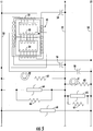
Figure 4 is a schematic diagram of an example single phase 120 volt power conditioner implementation. In this embodiment, thefirst lead 40 of thefirst coil 30 is connected to the line 50 (L1) of an AC power source to be conditioned. Thesecond lead 41 of thefirst coil 30 is connected at its free end to the neutral 52 (N) of the AC power source via acapacitor 54. Similarly, thefirst lead 44 of thethird coil 34 is connected to the line 50 (L1) of the AC power source, and thesecond lead 45 is connected at its free end to neutral 52 through acapacitor 56.Second coil 32 is coupled betweenline 50 and neutral 52 as well. In particular,line 42 ofsecond coil 32 is coupled to line 50 (L1) andline 43 of thesecond coil 32 is coupled to neutral 52 (N) viacapacitor 58. - The embodiment of
Figure 4 includes various additional components. A lamp 60 (e.g., LED or incandescent) is connected betweenline 50 and neutral 52 via a current limitingresistor 62. Transient suppression is provided by a varistor (e.g., MOV) 64 coupled between L1 and neutral. Ableed resistor 66 is coupled in parallel withvaristor 64 to bleed off stored charges, thereby reducing the possibility of electrical shock to an electrician working with the unit after power has been turned off. -
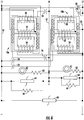
Figure 5 is a schematic diagram of an example 240 volt recreational unit (e.g., for watercraft) having line 50 (L1), line 53 (L2) and neutral 52 (N). As with the embodiment ofFigure 4 , asingle choke 10 is used with the first, second andthird coils lamp 61 andseries resistor 63,varistor 65 withparallel bleed resistor 67, andvaristor 68. -
Figure 6 shows an example 240 volt three phase power conditioner implementation using the multi-coil chokes 10 of the present invention. In this embodiment, twoidentical chokes choke 10 illustrated inFigure 3 . The first, second andthird coils capacitors -
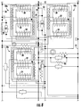
Figure 7 shows a three phase embodiment suitable, e.g., for a 480 volt power conditioner installed on an AC source having three hot lines 50 (L1), 53 (L2) and 55 (L3). Threechokes choke 10 shown inFigure 3 . The first, second andthird coils lamp 80 andseries resistor 81, andcapacitors additional bleed resistor 69 is also provided acrossvaristor 68. -
Figure 8 is a schematic diagram of an example power conditioner used for, e.g., a 208 volt or 480 volt 3 phase Y configured AC power source. Such a power source has three hot lines and a neutral. These are shown inFigure 8 as line 50 (L1), line 53 (L2), line 55 (L3) and neutral 52 (N). Threechokes choke 10 shown inFigure 3 . The first, second andthird coils varistor 85 andresistor 86. - The multi-coil choke of the present invention provides power conditioners with improved transient and surge protection as well as substantial energy savings over prior art power conditioners, including significant improvements over the power conditioners disclosed in
US Patent 5,105,327 . Transient and surge protection is provided by the various capacitors and transient suppressors. As shown in the drawings, capacitors are provided across power lines. Transient suppressors, such as metal oxide varistor ("MOV") devices can be placed at various points throughout the circuit. An MOV can be placed across incoming power lines. An MOV can be coupled from incoming lines to neutral. MOVs can be placed between neutral and ground. Bleed resistors across the transient suppressors take down the charge held by the circuit to protect against electrical shock when the unit is disconnected from the AC power source. - The values of the various components shown will depend upon the AC power source to be conditioned and the loads to be protected by the power conditioners. Typically, the capacitors will be between 25-100 microfarads and will have a voltage limit that is suitable for the maximum voltage to be applied to the power conditioner. The bleed down resistors placed across the varistors will be on the order of 30K Ω to 100K Ω or more with a typical power rating of 2 watts. The MOV devices used for the transient suppressors will typically be selected to have a rating of about 40,000 joules each.
- Power conditioners using the multi-coil chokes disclosed herein are frequency independent, so that they can work on both 60 Hz line current found in North America as well as on 50 Hz current used elsewhere in the world. Power conditioners manufactured using the inventive chokes are vastly improved over prior art devices due to various factors, including the three leg core design, the provision of five coils in each choke with the winding configuration taught herein, and the four separate air gaps provided in the core. These air gaps are shown most clearly in
Figure 1 asgaps 16, 18 (18a and 18b), 22 and 24. Tests have shown that energy savings are about double the savings provided by prior art devices of the type shown inUS Patent 5,105,327 , with faster surge suppression and the ability to handle larger surges. The improvements in surge suppression are achieved, at least in part, due to the multiple air gaps provided in the chokes which prevent the chokes from saturating. Better filtering is also provided by power conditioners using the chokes of the present invention. - The components of the power conditioner can be provided in a module that is connected to a user's power lines at the service panel. Alternatively, the module can be connected to the user's power lines at a load. A plurality of such modules can be provided throughout a commercial establishment or residence. For example, one module can be installed at each fluorescent light fixture in an office building or on each separate line feeding such lighting fixtures. Connections to the module are made at taps on the power lines. There is no need to cut the power lines when installing the module, since none of the components are placed in series with any of the lines.
- While the present invention has been described with reference to various example embodiments, it will be understood by those skilled in the art that various changes may be made and equivalents may be substituted for elements thereof without departing from the scope of the invention. In addition, many modifications may be made to adapt a particular situation or material to the teachings without departing from the essential scope thereof. Therefore, it is intended that the invention not be limited to the particular embodiments disclosed as the best mode contemplated for carrying out this invention, but that the invention will include all embodiments falling within the scope of the appended claims.
Claims (12)
- A multi-coil choke comprising:a magnetic core (10) having a first leg (31), a second leg (33a, 33b), and a third leg (35), said legs being substantially parallel to each other;a first coil (30) wrapped around said first leg (31) and terminating in a first lead (40) at a first end thereof and a second lead (41) at a second end thereof;a second coil (32) wrapped around said second leg (33a, 33b) and terminating in a first lead (42) at a first end thereof and a second lead (43) at a second end thereof;a third coil (34) wrapped around said third leg (35) and terminating in a first lead (44) at a first end thereof and a second lead (45) at a second end thereof;a fourth coil (36) formed from a proximal portion of the second lead (41) of said first coil (30), said fourth coil (36) being wrapped around a distal portion (45') of the second lead (45) of said third coil (34); anda fifth coil (38) formed from a proximal portion of the second lead (45) of said third coil (34), said fifth coil being wrapped around a distal portion (41') of the second lead (41) of said first coil (30), wherein:the distal portion (41') of the second lead (41) of said first coil (30) passes through said third coil (34) before passing through said fifth coil (38); andthe distal portion (45") of the second lead (45) of said third coil (34) passes through said first coil (30) before passing through said fourth coil (36), andwherein said first coil (30) is wrapped in one of a clockwise and counterclockwise direction, and said second and third coils (32, 34) are wrapped in the other of said clockwise and counterclockwise direction.
- A multi-coil choke in accordance with claim 1 wherein said magnetic core (10) is formed from two rectangular closed cores (12, 14) placed side-by-side with adjacent sides forming said second leg (33a, 33b).
- A multi-coil choke in accordance with claim 2 wherein:said first leg (31) includes a gap (16);said second leg (33a, 33b) includes substantially aligned gaps (18a, 18b) in the adjacent sides of said rectangular closed cores (12, 14); andsaid third leg (35) includes a gap (22).
- A multi-coil choke in accordance with claim 3 comprising an additional gap (24) along the length of the adjacent sides of said rectangular closed cores (12, 14).
- A multi-coil choke in accordance with claim 3 wherein said gaps (16, 18a, 18b, 22) are centrally located along their respective legs (31, 33a, 33b, 35).
- A multi-coil choke in accordance with any of claims 2 to 5 wherein each of said rectangular closed cores (12, 14) is contained within an insulating cover (13, 15).
- A multi-coil choke in accordance with any one of claims 1 to 6 wherein said fourth coil (36) is wrapped in the same direction as said first coil (30) and said fifth coil (38) is wrapped in the same direction as said third coil (34).
- A multi-coil choke in accordance with any of claims 1 to 7 wherein said first and fourth coils (30, 36) are wrapped in a counterclockwise direction, and said second, third and fifth coils (32, 34, 38) are wrapped in a clockwise direction.
- A power conditioner for AC power lines comprising:a multi-coil choke in accordance with claims 1 to 8;at least one capacitor (54, 56, 58); andmeans for coupling said choke and at least one capacitor (54, 56, 58) in series across an AC power source.
- A power conditioner in accordance with claim 9 comprising a plurality of said multi-coil chokes, each coupled in series with at least one capacitor (54, 56, 58, 70, 72, 74, 83, 84, 85) across a respective AC power source.
- A power conditioner in accordance with claim 10 wherein said means for coupling are adapted to couple each of said multi-coil chokes with:said first and fourth coils (30, 36) in series with at least one capacitor (54, 74, 85) across a respective AC power source;said second coil (32) in series with at least one capacitor (58, 72, 83) across a respective AC power source; andsaid third and fifth coils (34, 38) in series with at least one capacitor (56, 70, 84) across a respective AC power source.
- A power conditioner in accordance with claim 9, wherein said means for coupling are adapted to couple:said first and fourth coils (30, 36) in series with at least one capacitor (54) across a respective AC power source;said second coil (32) in series with at least one capacitor (58) across a respective AC power source; andsaid third and fifth coils (34, 38) in series with at least one capacitor (56) across a respective AC power source.
Applications Claiming Priority (2)
| Application Number | Priority Date | Filing Date | Title |
|---|---|---|---|
| US13/015,694 US8791782B2 (en) | 2011-01-28 | 2011-01-28 | AC power conditioning circuit |
| PCT/US2011/001251 WO2012102691A1 (en) | 2011-01-28 | 2011-07-15 | Ac power conditioning circuit |
Publications (3)
| Publication Number | Publication Date |
|---|---|
| EP2668658A1 EP2668658A1 (en) | 2013-12-04 |
| EP2668658A4 EP2668658A4 (en) | 2017-10-18 |
| EP2668658B1 true EP2668658B1 (en) | 2019-03-06 |
Family
ID=46576884
Family Applications (1)
| Application Number | Title | Priority Date | Filing Date |
|---|---|---|---|
| EP11857171.0A Active EP2668658B1 (en) | 2011-01-28 | 2011-07-15 | Ac power conditioning circuit |
Country Status (16)
| Country | Link |
|---|---|
| US (1) | US8791782B2 (en) |
| EP (1) | EP2668658B1 (en) |
| JP (1) | JP5788998B2 (en) |
| KR (1) | KR101816957B1 (en) |
| CN (1) | CN103282981B (en) |
| AU (1) | AU2011356733B2 (en) |
| BR (1) | BR112013014716B1 (en) |
| CA (1) | CA2817720C (en) |
| ES (1) | ES2729701T3 (en) |
| HK (1) | HK1187146A1 (en) |
| IL (1) | IL226657A (en) |
| MX (1) | MX2013008399A (en) |
| RU (1) | RU2547145C2 (en) |
| SG (1) | SG190302A1 (en) |
| TR (1) | TR201904175T4 (en) |
| WO (1) | WO2012102691A1 (en) |
Families Citing this family (13)
| Publication number | Priority date | Publication date | Assignee | Title |
|---|---|---|---|---|
| EP2591200B1 (en) * | 2010-07-05 | 2019-04-10 | Services Petroliers Schlumberger (SPS) | Inductive couplers for use in a downhole environment |
| CN102436907B (en) * | 2011-12-22 | 2014-01-01 | 广州金升阳科技有限公司 | Magnetic core for transformer |
| US9951609B2 (en) | 2012-03-08 | 2018-04-24 | Zenith Oilfield Technology Limited | Data communications system |
| US8773231B2 (en) * | 2012-03-09 | 2014-07-08 | Raytheon Company | Multiphase power converters involving controllable inductors |
| MY180311A (en) * | 2012-10-15 | 2020-11-28 | Epizyme Inc | Substituted benzene compounds |
| US9263961B2 (en) | 2013-07-23 | 2016-02-16 | Raytheon Company | Wide input DC/DC resonant converter to control reactive power |
| JP2015041625A (en) * | 2013-08-20 | 2015-03-02 | 株式会社アイキューフォー | Reactor, composite core for reactor, and composite core formation member for reactor |
| US9407150B2 (en) * | 2013-09-06 | 2016-08-02 | Raytheon Company | High efficiency zero-voltage switching (ZVS) assistance circuit for power converter |
| GB201407338D0 (en) * | 2014-04-25 | 2014-06-11 | Gridon Ltd | Fault current limiter |
| JP2015233033A (en) * | 2014-06-09 | 2015-12-24 | パナソニックIpマネジメント株式会社 | Coil structure and power supply device |
| WO2016088460A1 (en) * | 2014-12-03 | 2016-06-09 | 三菱電機株式会社 | Dual-mode choke coil and high-frequency filter using same, and on-board motor integrated electric power steering and on-board charging device |
| CN113113206B (en) | 2017-10-17 | 2022-10-18 | 台达电子工业股份有限公司 | Integrated magnetic element |
| WO2022088178A1 (en) * | 2020-11-02 | 2022-05-05 | Telefonaktiebolaget Lm Ericsson (Publ) | Integrated magnetic device and filter circuit |
Family Cites Families (43)
| Publication number | Priority date | Publication date | Assignee | Title |
|---|---|---|---|---|
| US1647928A (en) * | 1925-11-14 | 1927-11-01 | Frederick C Owen | Transformer for electric-arc cutting and welding apparatus |
| US2792556A (en) * | 1953-08-20 | 1957-05-14 | Westinghouse Electric Corp | Ballast |
| US3247449A (en) | 1957-03-15 | 1966-04-19 | Fox Prod Co | Transformer apparatus |
| SU121182A1 (en) * | 1958-07-19 | 1958-11-30 | Ю.К. Захаров | AC throttle voltage regulator |
| US4019122A (en) | 1974-08-14 | 1977-04-19 | Telcon-Magnetic Cores Limited | Stabilized power supplies |
| DE2513168C3 (en) | 1975-03-25 | 1978-06-08 | Siemens Ag, 1000 Berlin Und 8000 Muenchen | Device for reactive power compensation in a three-phase network |
| US4117524A (en) | 1975-10-03 | 1978-09-26 | Reyrolle Parsons Limited | Current-limiting devices |
| US4152743A (en) | 1977-06-27 | 1979-05-01 | Comstock Wilford K | Transient voltage suppression system |
| US4259705A (en) | 1979-03-27 | 1981-03-31 | Stifter Francis J | Combination surge suppressor filter |
| GB2115627B (en) | 1982-02-20 | 1986-04-30 | Transtar Limited | Power supplies |
| US4672298A (en) | 1983-05-06 | 1987-06-09 | Frederick Rohatyn | Power factor correction system |
| US4531085A (en) | 1983-06-13 | 1985-07-23 | Power Distribution Inc. | Polyphase line voltage regulator |
| FR2559268B1 (en) | 1984-02-06 | 1986-05-09 | Centre Nat Rech Scient | DEVICE FOR MEASURING AN ELECTRIC CURRENT USING A REGULAR TORO-SHAPED SOLENOID |
| JPS60183963A (en) * | 1984-02-29 | 1985-09-19 | Yashima Denki Kk | Phase control circuit of ac power using 3-leg core transformer |
| US4587588A (en) | 1984-03-02 | 1986-05-06 | Perma Power Electronics, Inc. | Power line transient surge suppressor |
| US4584622A (en) | 1984-07-09 | 1986-04-22 | Gte Products Corporation | Transient voltage surge suppressor |
| EP0187983B1 (en) | 1985-01-15 | 1989-11-29 | BBC Brown Boveri AG | Filter ciruit including zn0 overvoltage arresters |
| DE3508495A1 (en) | 1985-03-09 | 1986-09-11 | Johann Leonhard 8540 Schwabach Hüttlinger | Method for producing a coil or the like |
| FR2601526A2 (en) | 1986-07-11 | 1988-01-15 | Cables De Lyon Geoffroy Delore | DEVICE FOR PROTECTING AN ELECTRIC POWER LINE AGAINST HIGH TRANSIENT OVERVOLTAGES |
| US4845580A (en) | 1986-08-27 | 1989-07-04 | Kitchens William B | A.C.-D.C. Spike eliminating bandpass filter |
| US4866560A (en) | 1988-04-22 | 1989-09-12 | Allina Edward F | Safeguarding electrical transient surge protection |
| US4739436A (en) | 1986-12-15 | 1988-04-19 | General Electric Company | Surge suppression circuit |
| US4802055A (en) | 1987-10-26 | 1989-01-31 | Joseph L. Brooks Manufacturing Corp. | Transient voltage surge suppressor |
| CH676763A5 (en) | 1988-01-14 | 1991-02-28 | Susanne Riedi Joks | |
| US4901183A (en) | 1988-08-29 | 1990-02-13 | World Products, Inc. | Surge protection device |
| US4870534A (en) | 1988-09-02 | 1989-09-26 | Harford Jack R | Power line surge suppressor |
| JPH02266504A (en) * | 1989-04-06 | 1990-10-31 | Daihen Corp | Stationary induction electric apparatus and manufacture thereof |
| US5105327A (en) * | 1990-05-10 | 1992-04-14 | Uses, Inc. | Ac power conditioning circuit |
| RU2073275C1 (en) * | 1993-06-28 | 1997-02-10 | Научно-исследовательский институт радиостроения | Filter choke |
| JPH07297055A (en) * | 1994-04-26 | 1995-11-10 | Matsushita Electric Ind Co Ltd | Choke coil |
| CA2208482C (en) | 1994-12-21 | 2000-04-11 | Wolfgang Hill | Transverse flux machine |
| US5942828A (en) | 1995-12-16 | 1999-08-24 | Hill; Wolfgang | Transverse flux machine |
| RU2106712C1 (en) * | 1996-11-20 | 1998-03-10 | Открытое акционерное общество "Российская электротехническая компания" | Saturation choke |
| JP2000353627A (en) * | 1999-06-10 | 2000-12-19 | Sony Corp | Insulating converter transformer and switching power supply circuit |
| US6512438B1 (en) * | 1999-12-16 | 2003-01-28 | Honeywell International Inc. | Inductor core-coil assembly and manufacturing thereof |
| US7136293B2 (en) | 2004-06-24 | 2006-11-14 | Petkov Roumen D | Full wave series resonant type DC to DC power converter with integrated magnetics |
| US6980077B1 (en) * | 2004-08-19 | 2005-12-27 | Coldwatt, Inc. | Composite magnetic core for switch-mode power converters |
| JP2006222387A (en) * | 2005-02-14 | 2006-08-24 | Toshiba Corp | Choke coil unit |
| US7142081B1 (en) | 2005-05-03 | 2006-11-28 | Mte Corporation | Multiple three-phase inductor with a common core |
| JP2008048527A (en) * | 2006-08-14 | 2008-02-28 | Ntt Data Ex Techno Corp | Switching power circuit and transformer |
| TW200824215A (en) | 2006-11-23 | 2008-06-01 | Univ Nat Central | A non-contact type power supply device having load and interval detection |
| US20090167473A1 (en) | 2007-12-27 | 2009-07-02 | Wen-Sen Hsieh | Transformer structure |
| CN201213091Y (en) * | 2008-05-28 | 2009-03-25 | 王学才 | Magnet leakage self-shielding type controllable reactor with magnetic circuit in parallel |
-
2011
- 2011-01-28 US US13/015,694 patent/US8791782B2/en active Active
- 2011-07-15 EP EP11857171.0A patent/EP2668658B1/en active Active
- 2011-07-15 CA CA2817720A patent/CA2817720C/en active Active
- 2011-07-15 BR BR112013014716-4A patent/BR112013014716B1/en active IP Right Grant
- 2011-07-15 ES ES11857171T patent/ES2729701T3/en active Active
- 2011-07-15 RU RU2013139864/07A patent/RU2547145C2/en active
- 2011-07-15 JP JP2013551945A patent/JP5788998B2/en active Active
- 2011-07-15 TR TR2019/04175T patent/TR201904175T4/en unknown
- 2011-07-15 WO PCT/US2011/001251 patent/WO2012102691A1/en active Application Filing
- 2011-07-15 CN CN201180063165.8A patent/CN103282981B/en active Active
- 2011-07-15 MX MX2013008399A patent/MX2013008399A/en active IP Right Grant
- 2011-07-15 AU AU2011356733A patent/AU2011356733B2/en active Active
- 2011-07-15 KR KR1020137013089A patent/KR101816957B1/en active IP Right Grant
- 2011-07-15 SG SG2013037601A patent/SG190302A1/en unknown
-
2013
- 2013-05-30 IL IL226657A patent/IL226657A/en active IP Right Grant
-
2014
- 2014-01-03 HK HK14100041.3A patent/HK1187146A1/en unknown
Non-Patent Citations (1)
| Title |
|---|
| None * |
Also Published As
| Publication number | Publication date |
|---|---|
| BR112013014716A2 (en) | 2017-09-26 |
| MX2013008399A (en) | 2013-09-13 |
| HK1187146A1 (en) | 2014-03-28 |
| TR201904175T4 (en) | 2019-04-22 |
| CN103282981B (en) | 2016-05-25 |
| BR112013014716B1 (en) | 2020-11-03 |
| JP2014505372A (en) | 2014-02-27 |
| AU2011356733A1 (en) | 2013-06-06 |
| IL226657A (en) | 2016-11-30 |
| CN103282981A (en) | 2013-09-04 |
| US8791782B2 (en) | 2014-07-29 |
| US20120194313A1 (en) | 2012-08-02 |
| RU2013139864A (en) | 2015-03-10 |
| KR20130140742A (en) | 2013-12-24 |
| SG190302A1 (en) | 2013-06-28 |
| EP2668658A4 (en) | 2017-10-18 |
| CA2817720A1 (en) | 2012-08-02 |
| RU2547145C2 (en) | 2015-04-10 |
| CA2817720C (en) | 2017-09-12 |
| JP5788998B2 (en) | 2015-10-07 |
| EP2668658A1 (en) | 2013-12-04 |
| AU2011356733B2 (en) | 2016-04-14 |
| KR101816957B1 (en) | 2018-01-09 |
| WO2012102691A1 (en) | 2012-08-02 |
| ES2729701T3 (en) | 2019-11-05 |
Similar Documents
| Publication | Publication Date | Title |
|---|---|---|
| EP2668658B1 (en) | Ac power conditioning circuit | |
| CA2689029C (en) | Device for filtering harmonics | |
| KR960013761B1 (en) | Ac power conditioning circuit | |
| KR101828831B1 (en) | A transformer having the advanced functions for attenuating higher harmonics and recovering an open-phase | |
| EP2169692A1 (en) | High voltage step-up dry power transformer and power supply unit comprising at least one such transformer | |
| US8866575B2 (en) | AC power conditioning circuit | |
| KR100990329B1 (en) | Regulation apparatus of three phase distribution line for removing the harmonics | |
| KR102043260B1 (en) | Smart hybrid transformer with enhanced harmonic attenuation and large current phase recovery | |
| US9859713B2 (en) | Parallel inverters connected to one inductor | |
| KR102571731B1 (en) | Three phase electric power lottery transformer | |
| KR20190094920A (en) | A transformer having the advanced functions for attenuating higher harmonics and recovering an open-phase | |
| US10298113B2 (en) | Filter for a power network | |
| KR101374647B1 (en) | Compact type three phase electric pole transformer | |
| RU2657233C2 (en) | Line filter | |
| KR20180062586A (en) | Transformer | |
| JPH0443619A (en) | Transformer equiped with tertiary winding |
Legal Events
| Date | Code | Title | Description |
|---|---|---|---|
| PUAI | Public reference made under article 153(3) epc to a published international application that has entered the european phase |
Free format text: ORIGINAL CODE: 0009012 |
|
| 17P | Request for examination filed |
Effective date: 20130813 |
|
| AK | Designated contracting states |
Kind code of ref document: A1 Designated state(s): AL AT BE BG CH CY CZ DE DK EE ES FI FR GB GR HR HU IE IS IT LI LT LU LV MC MK MT NL NO PL PT RO RS SE SI SK SM TR |
|
| DAX | Request for extension of the european patent (deleted) | ||
| RA4 | Supplementary search report drawn up and despatched (corrected) |
Effective date: 20170914 |
|
| RIC1 | Information provided on ipc code assigned before grant |
Ipc: H01F 27/34 20060101ALI20170908BHEP Ipc: H01F 27/28 20060101AFI20170908BHEP Ipc: H01F 27/38 20060101ALI20170908BHEP |
|
| GRAP | Despatch of communication of intention to grant a patent |
Free format text: ORIGINAL CODE: EPIDOSNIGR1 |
|
| STAA | Information on the status of an ep patent application or granted ep patent |
Free format text: STATUS: GRANT OF PATENT IS INTENDED |
|
| INTG | Intention to grant announced |
Effective date: 20180508 |
|
| GRAJ | Information related to disapproval of communication of intention to grant by the applicant or resumption of examination proceedings by the epo deleted |
Free format text: ORIGINAL CODE: EPIDOSDIGR1 |
|
| STAA | Information on the status of an ep patent application or granted ep patent |
Free format text: STATUS: REQUEST FOR EXAMINATION WAS MADE |
|
| INTC | Intention to grant announced (deleted) | ||
| GRAP | Despatch of communication of intention to grant a patent |
Free format text: ORIGINAL CODE: EPIDOSNIGR1 |
|
| STAA | Information on the status of an ep patent application or granted ep patent |
Free format text: STATUS: GRANT OF PATENT IS INTENDED |
|
| INTG | Intention to grant announced |
Effective date: 20181005 |
|
| GRAS | Grant fee paid |
Free format text: ORIGINAL CODE: EPIDOSNIGR3 |
|
| GRAA | (expected) grant |
Free format text: ORIGINAL CODE: 0009210 |
|
| STAA | Information on the status of an ep patent application or granted ep patent |
Free format text: STATUS: THE PATENT HAS BEEN GRANTED |
|
| AK | Designated contracting states |
Kind code of ref document: B1 Designated state(s): AL AT BE BG CH CY CZ DE DK EE ES FI FR GB GR HR HU IE IS IT LI LT LU LV MC MK MT NL NO PL PT RO RS SE SI SK SM TR |
|
| REG | Reference to a national code |
Ref country code: GB Ref legal event code: FG4D |
|
| REG | Reference to a national code |
Ref country code: CH Ref legal event code: EP Ref country code: AT Ref legal event code: REF Ref document number: 1105656 Country of ref document: AT Kind code of ref document: T Effective date: 20190315 |
|
| REG | Reference to a national code |
Ref country code: DE Ref legal event code: R096 Ref document number: 602011057006 Country of ref document: DE |
|
| REG | Reference to a national code |
Ref country code: IE Ref legal event code: FG4D |
|
| REG | Reference to a national code |
Ref country code: NL Ref legal event code: FP |
|
| REG | Reference to a national code |
Ref country code: SE Ref legal event code: TRGR |
|
| REG | Reference to a national code |
Ref country code: LT Ref legal event code: MG4D |
|
| PG25 | Lapsed in a contracting state [announced via postgrant information from national office to epo] |
Ref country code: LT Free format text: LAPSE BECAUSE OF FAILURE TO SUBMIT A TRANSLATION OF THE DESCRIPTION OR TO PAY THE FEE WITHIN THE PRESCRIBED TIME-LIMIT Effective date: 20190306 Ref country code: NO Free format text: LAPSE BECAUSE OF FAILURE TO SUBMIT A TRANSLATION OF THE DESCRIPTION OR TO PAY THE FEE WITHIN THE PRESCRIBED TIME-LIMIT Effective date: 20190606 Ref country code: FI Free format text: LAPSE BECAUSE OF FAILURE TO SUBMIT A TRANSLATION OF THE DESCRIPTION OR TO PAY THE FEE WITHIN THE PRESCRIBED TIME-LIMIT Effective date: 20190306 |
|
| PG25 | Lapsed in a contracting state [announced via postgrant information from national office to epo] |
Ref country code: BG Free format text: LAPSE BECAUSE OF FAILURE TO SUBMIT A TRANSLATION OF THE DESCRIPTION OR TO PAY THE FEE WITHIN THE PRESCRIBED TIME-LIMIT Effective date: 20190606 Ref country code: LV Free format text: LAPSE BECAUSE OF FAILURE TO SUBMIT A TRANSLATION OF THE DESCRIPTION OR TO PAY THE FEE WITHIN THE PRESCRIBED TIME-LIMIT Effective date: 20190306 Ref country code: RS Free format text: LAPSE BECAUSE OF FAILURE TO SUBMIT A TRANSLATION OF THE DESCRIPTION OR TO PAY THE FEE WITHIN THE PRESCRIBED TIME-LIMIT Effective date: 20190306 Ref country code: HR Free format text: LAPSE BECAUSE OF FAILURE TO SUBMIT A TRANSLATION OF THE DESCRIPTION OR TO PAY THE FEE WITHIN THE PRESCRIBED TIME-LIMIT Effective date: 20190306 |
|
| REG | Reference to a national code |
Ref country code: GR Ref legal event code: EP Ref document number: 20190401683 Country of ref document: GR Effective date: 20190906 |
|
| PG25 | Lapsed in a contracting state [announced via postgrant information from national office to epo] |
Ref country code: AL Free format text: LAPSE BECAUSE OF FAILURE TO SUBMIT A TRANSLATION OF THE DESCRIPTION OR TO PAY THE FEE WITHIN THE PRESCRIBED TIME-LIMIT Effective date: 20190306 Ref country code: CZ Free format text: LAPSE BECAUSE OF FAILURE TO SUBMIT A TRANSLATION OF THE DESCRIPTION OR TO PAY THE FEE WITHIN THE PRESCRIBED TIME-LIMIT Effective date: 20190306 Ref country code: RO Free format text: LAPSE BECAUSE OF FAILURE TO SUBMIT A TRANSLATION OF THE DESCRIPTION OR TO PAY THE FEE WITHIN THE PRESCRIBED TIME-LIMIT Effective date: 20190306 Ref country code: SK Free format text: LAPSE BECAUSE OF FAILURE TO SUBMIT A TRANSLATION OF THE DESCRIPTION OR TO PAY THE FEE WITHIN THE PRESCRIBED TIME-LIMIT Effective date: 20190306 Ref country code: PT Free format text: LAPSE BECAUSE OF FAILURE TO SUBMIT A TRANSLATION OF THE DESCRIPTION OR TO PAY THE FEE WITHIN THE PRESCRIBED TIME-LIMIT Effective date: 20190706 Ref country code: EE Free format text: LAPSE BECAUSE OF FAILURE TO SUBMIT A TRANSLATION OF THE DESCRIPTION OR TO PAY THE FEE WITHIN THE PRESCRIBED TIME-LIMIT Effective date: 20190306 |
|
| REG | Reference to a national code |
Ref country code: ES Ref legal event code: FG2A Ref document number: 2729701 Country of ref document: ES Kind code of ref document: T3 Effective date: 20191105 |
|
| PG25 | Lapsed in a contracting state [announced via postgrant information from national office to epo] |
Ref country code: SM Free format text: LAPSE BECAUSE OF FAILURE TO SUBMIT A TRANSLATION OF THE DESCRIPTION OR TO PAY THE FEE WITHIN THE PRESCRIBED TIME-LIMIT Effective date: 20190306 Ref country code: PL Free format text: LAPSE BECAUSE OF FAILURE TO SUBMIT A TRANSLATION OF THE DESCRIPTION OR TO PAY THE FEE WITHIN THE PRESCRIBED TIME-LIMIT Effective date: 20190306 |
|
| REG | Reference to a national code |
Ref country code: DE Ref legal event code: R097 Ref document number: 602011057006 Country of ref document: DE |
|
| PG25 | Lapsed in a contracting state [announced via postgrant information from national office to epo] |
Ref country code: IS Free format text: LAPSE BECAUSE OF FAILURE TO SUBMIT A TRANSLATION OF THE DESCRIPTION OR TO PAY THE FEE WITHIN THE PRESCRIBED TIME-LIMIT Effective date: 20190706 |
|
| PLBE | No opposition filed within time limit |
Free format text: ORIGINAL CODE: 0009261 |
|
| STAA | Information on the status of an ep patent application or granted ep patent |
Free format text: STATUS: NO OPPOSITION FILED WITHIN TIME LIMIT |
|
| PG25 | Lapsed in a contracting state [announced via postgrant information from national office to epo] |
Ref country code: DK Free format text: LAPSE BECAUSE OF FAILURE TO SUBMIT A TRANSLATION OF THE DESCRIPTION OR TO PAY THE FEE WITHIN THE PRESCRIBED TIME-LIMIT Effective date: 20190306 |
|
| 26N | No opposition filed |
Effective date: 20191209 |
|
| PG25 | Lapsed in a contracting state [announced via postgrant information from national office to epo] |
Ref country code: SI Free format text: LAPSE BECAUSE OF FAILURE TO SUBMIT A TRANSLATION OF THE DESCRIPTION OR TO PAY THE FEE WITHIN THE PRESCRIBED TIME-LIMIT Effective date: 20190306 Ref country code: MC Free format text: LAPSE BECAUSE OF FAILURE TO SUBMIT A TRANSLATION OF THE DESCRIPTION OR TO PAY THE FEE WITHIN THE PRESCRIBED TIME-LIMIT Effective date: 20190306 |
|
| PG25 | Lapsed in a contracting state [announced via postgrant information from national office to epo] |
Ref country code: LU Free format text: LAPSE BECAUSE OF NON-PAYMENT OF DUE FEES Effective date: 20190715 |
|
| PG25 | Lapsed in a contracting state [announced via postgrant information from national office to epo] |
Ref country code: IE Free format text: LAPSE BECAUSE OF NON-PAYMENT OF DUE FEES Effective date: 20190715 |
|
| PG25 | Lapsed in a contracting state [announced via postgrant information from national office to epo] |
Ref country code: CY Free format text: LAPSE BECAUSE OF FAILURE TO SUBMIT A TRANSLATION OF THE DESCRIPTION OR TO PAY THE FEE WITHIN THE PRESCRIBED TIME-LIMIT Effective date: 20190306 |
|
| PG25 | Lapsed in a contracting state [announced via postgrant information from national office to epo] |
Ref country code: MT Free format text: LAPSE BECAUSE OF FAILURE TO SUBMIT A TRANSLATION OF THE DESCRIPTION OR TO PAY THE FEE WITHIN THE PRESCRIBED TIME-LIMIT Effective date: 20190306 Ref country code: HU Free format text: LAPSE BECAUSE OF FAILURE TO SUBMIT A TRANSLATION OF THE DESCRIPTION OR TO PAY THE FEE WITHIN THE PRESCRIBED TIME-LIMIT; INVALID AB INITIO Effective date: 20110715 |
|
| REG | Reference to a national code |
Ref country code: AT Ref legal event code: UEP Ref document number: 1105656 Country of ref document: AT Kind code of ref document: T Effective date: 20190306 |
|
| PG25 | Lapsed in a contracting state [announced via postgrant information from national office to epo] |
Ref country code: MK Free format text: LAPSE BECAUSE OF FAILURE TO SUBMIT A TRANSLATION OF THE DESCRIPTION OR TO PAY THE FEE WITHIN THE PRESCRIBED TIME-LIMIT Effective date: 20190306 |
|
| P01 | Opt-out of the competence of the unified patent court (upc) registered |
Effective date: 20230522 |
|
| PGFP | Annual fee paid to national office [announced via postgrant information from national office to epo] |
Ref country code: IT Payment date: 20230612 Year of fee payment: 13 |
|
| PGFP | Annual fee paid to national office [announced via postgrant information from national office to epo] |
Ref country code: TR Payment date: 20230713 Year of fee payment: 13 Ref country code: ES Payment date: 20230808 Year of fee payment: 13 Ref country code: CH Payment date: 20230801 Year of fee payment: 13 Ref country code: AT Payment date: 20230626 Year of fee payment: 13 |
|
| PGFP | Annual fee paid to national office [announced via postgrant information from national office to epo] |
Ref country code: DE Payment date: 20230327 Year of fee payment: 13 |
|
| PGFP | Annual fee paid to national office [announced via postgrant information from national office to epo] |
Ref country code: NL Payment date: 20240515 Year of fee payment: 14 |
|
| PGFP | Annual fee paid to national office [announced via postgrant information from national office to epo] |
Ref country code: GB Payment date: 20240524 Year of fee payment: 14 |
|
| PGFP | Annual fee paid to national office [announced via postgrant information from national office to epo] |
Ref country code: GR Payment date: 20240617 Year of fee payment: 14 |
|
| PGFP | Annual fee paid to national office [announced via postgrant information from national office to epo] |
Ref country code: FR Payment date: 20240509 Year of fee payment: 14 |
|
| PGFP | Annual fee paid to national office [announced via postgrant information from national office to epo] |
Ref country code: SE Payment date: 20240510 Year of fee payment: 14 Ref country code: BE Payment date: 20240617 Year of fee payment: 14 |