EP2667833B2 - Absorbent article - Google Patents
Absorbent article Download PDFInfo
- Publication number
- EP2667833B2 EP2667833B2 EP12739912.9A EP12739912A EP2667833B2 EP 2667833 B2 EP2667833 B2 EP 2667833B2 EP 12739912 A EP12739912 A EP 12739912A EP 2667833 B2 EP2667833 B2 EP 2667833B2
- Authority
- EP
- European Patent Office
- Prior art keywords
- hot melt
- melt adhesive
- article
- areas
- polymer particles
- Prior art date
- Legal status (The legal status is an assumption and is not a legal conclusion. Google has not performed a legal analysis and makes no representation as to the accuracy of the status listed.)
- Active
Links
- 239000002250 absorbent Substances 0.000 title claims description 40
- 230000002745 absorbent Effects 0.000 title claims description 38
- 239000004831 Hot glue Substances 0.000 claims description 76
- 239000007788 liquid Substances 0.000 claims description 58
- 239000002245 particle Substances 0.000 claims description 44
- 238000007789 sealing Methods 0.000 claims description 41
- 229920000247 superabsorbent polymer Polymers 0.000 claims description 40
- 239000004745 nonwoven fabric Substances 0.000 claims description 25
- 238000010521 absorption reaction Methods 0.000 claims description 15
- 230000002209 hydrophobic effect Effects 0.000 claims description 7
- 239000002985 plastic film Substances 0.000 claims description 7
- 229920006255 plastic film Polymers 0.000 claims description 7
- 239000012209 synthetic fiber Substances 0.000 claims description 7
- 229920002994 synthetic fiber Polymers 0.000 claims description 7
- 229920001169 thermoplastic Polymers 0.000 claims description 7
- 239000004416 thermosoftening plastic Substances 0.000 claims description 7
- 229920000642 polymer Polymers 0.000 claims description 5
- 210000002700 urine Anatomy 0.000 description 28
- 239000000463 material Substances 0.000 description 10
- 239000002131 composite material Substances 0.000 description 8
- 238000004519 manufacturing process Methods 0.000 description 8
- 239000000853 adhesive Substances 0.000 description 6
- 230000001070 adhesive effect Effects 0.000 description 6
- 239000000835 fiber Substances 0.000 description 5
- 210000001124 body fluid Anatomy 0.000 description 4
- 230000036544 posture Effects 0.000 description 4
- XLYOFNOQVPJJNP-UHFFFAOYSA-N water Substances O XLYOFNOQVPJJNP-UHFFFAOYSA-N 0.000 description 4
- 239000004744 fabric Substances 0.000 description 3
- 238000000034 method Methods 0.000 description 3
- 230000002093 peripheral effect Effects 0.000 description 3
- 239000012466 permeate Substances 0.000 description 3
- -1 polypropylene Polymers 0.000 description 3
- 238000000926 separation method Methods 0.000 description 3
- 238000009827 uniform distribution Methods 0.000 description 3
- 206010021639 Incontinence Diseases 0.000 description 2
- 239000004743 Polypropylene Substances 0.000 description 2
- 239000003795 chemical substances by application Substances 0.000 description 2
- 239000004615 ingredient Substances 0.000 description 2
- 229920001155 polypropylene Polymers 0.000 description 2
- 238000003825 pressing Methods 0.000 description 2
- 238000003892 spreading Methods 0.000 description 2
- 230000007480 spreading Effects 0.000 description 2
- 239000004698 Polyethylene Substances 0.000 description 1
- 239000010839 body fluid Substances 0.000 description 1
- 239000011248 coating agent Substances 0.000 description 1
- 238000000576 coating method Methods 0.000 description 1
- 239000000109 continuous material Substances 0.000 description 1
- 238000005520 cutting process Methods 0.000 description 1
- 230000003247 decreasing effect Effects 0.000 description 1
- 238000009826 distribution Methods 0.000 description 1
- 230000000694 effects Effects 0.000 description 1
- 239000000155 melt Substances 0.000 description 1
- 239000004750 melt-blown nonwoven Substances 0.000 description 1
- 230000004048 modification Effects 0.000 description 1
- 238000012986 modification Methods 0.000 description 1
- 230000035699 permeability Effects 0.000 description 1
- 229920001495 poly(sodium acrylate) polymer Polymers 0.000 description 1
- 229920000573 polyethylene Polymers 0.000 description 1
- 239000000843 powder Substances 0.000 description 1
- 239000000047 product Substances 0.000 description 1
- 239000011347 resin Substances 0.000 description 1
- 229920005989 resin Polymers 0.000 description 1
- 230000000717 retained effect Effects 0.000 description 1
- NNMHYFLPFNGQFZ-UHFFFAOYSA-M sodium polyacrylate Chemical compound [Na+].[O-]C(=O)C=C NNMHYFLPFNGQFZ-UHFFFAOYSA-M 0.000 description 1
- 238000011144 upstream manufacturing Methods 0.000 description 1
- 239000002351 wastewater Substances 0.000 description 1
- 238000003466 welding Methods 0.000 description 1
Images


Classifications
-
- A—HUMAN NECESSITIES
- A61—MEDICAL OR VETERINARY SCIENCE; HYGIENE
- A61F—FILTERS IMPLANTABLE INTO BLOOD VESSELS; PROSTHESES; DEVICES PROVIDING PATENCY TO, OR PREVENTING COLLAPSING OF, TUBULAR STRUCTURES OF THE BODY, e.g. STENTS; ORTHOPAEDIC, NURSING OR CONTRACEPTIVE DEVICES; FOMENTATION; TREATMENT OR PROTECTION OF EYES OR EARS; BANDAGES, DRESSINGS OR ABSORBENT PADS; FIRST-AID KITS
- A61F13/00—Bandages or dressings; Absorbent pads
- A61F13/15—Absorbent pads, e.g. sanitary towels, swabs or tampons for external or internal application to the body; Supporting or fastening means therefor; Tampon applicators
- A61F13/53—Absorbent pads, e.g. sanitary towels, swabs or tampons for external or internal application to the body; Supporting or fastening means therefor; Tampon applicators characterised by the absorbing medium
- A61F13/539—Absorbent pads, e.g. sanitary towels, swabs or tampons for external or internal application to the body; Supporting or fastening means therefor; Tampon applicators characterised by the absorbing medium characterised by the connection of the absorbent layers with each other or with the outer layers
-
- A—HUMAN NECESSITIES
- A61—MEDICAL OR VETERINARY SCIENCE; HYGIENE
- A61F—FILTERS IMPLANTABLE INTO BLOOD VESSELS; PROSTHESES; DEVICES PROVIDING PATENCY TO, OR PREVENTING COLLAPSING OF, TUBULAR STRUCTURES OF THE BODY, e.g. STENTS; ORTHOPAEDIC, NURSING OR CONTRACEPTIVE DEVICES; FOMENTATION; TREATMENT OR PROTECTION OF EYES OR EARS; BANDAGES, DRESSINGS OR ABSORBENT PADS; FIRST-AID KITS
- A61F13/00—Bandages or dressings; Absorbent pads
- A61F13/15—Absorbent pads, e.g. sanitary towels, swabs or tampons for external or internal application to the body; Supporting or fastening means therefor; Tampon applicators
- A61F13/15577—Apparatus or processes for manufacturing
- A61F13/15617—Making absorbent pads from fibres or pulverulent material with or without treatment of the fibres
- A61F13/15658—Forming continuous, e.g. composite, fibrous webs, e.g. involving the application of pulverulent material on parts thereof
-
- A—HUMAN NECESSITIES
- A61—MEDICAL OR VETERINARY SCIENCE; HYGIENE
- A61F—FILTERS IMPLANTABLE INTO BLOOD VESSELS; PROSTHESES; DEVICES PROVIDING PATENCY TO, OR PREVENTING COLLAPSING OF, TUBULAR STRUCTURES OF THE BODY, e.g. STENTS; ORTHOPAEDIC, NURSING OR CONTRACEPTIVE DEVICES; FOMENTATION; TREATMENT OR PROTECTION OF EYES OR EARS; BANDAGES, DRESSINGS OR ABSORBENT PADS; FIRST-AID KITS
- A61F13/00—Bandages or dressings; Absorbent pads
- A61F13/15—Absorbent pads, e.g. sanitary towels, swabs or tampons for external or internal application to the body; Supporting or fastening means therefor; Tampon applicators
- A61F13/53—Absorbent pads, e.g. sanitary towels, swabs or tampons for external or internal application to the body; Supporting or fastening means therefor; Tampon applicators characterised by the absorbing medium
- A61F13/531—Absorbent pads, e.g. sanitary towels, swabs or tampons for external or internal application to the body; Supporting or fastening means therefor; Tampon applicators characterised by the absorbing medium having a homogeneous composition through the thickness of the pad
- A61F13/532—Absorbent pads, e.g. sanitary towels, swabs or tampons for external or internal application to the body; Supporting or fastening means therefor; Tampon applicators characterised by the absorbing medium having a homogeneous composition through the thickness of the pad inhomogeneous in the plane of the pad
- A61F13/5323—Absorbent pads, e.g. sanitary towels, swabs or tampons for external or internal application to the body; Supporting or fastening means therefor; Tampon applicators characterised by the absorbing medium having a homogeneous composition through the thickness of the pad inhomogeneous in the plane of the pad having absorbent material located in discrete regions, e.g. pockets
-
- A—HUMAN NECESSITIES
- A61—MEDICAL OR VETERINARY SCIENCE; HYGIENE
- A61F—FILTERS IMPLANTABLE INTO BLOOD VESSELS; PROSTHESES; DEVICES PROVIDING PATENCY TO, OR PREVENTING COLLAPSING OF, TUBULAR STRUCTURES OF THE BODY, e.g. STENTS; ORTHOPAEDIC, NURSING OR CONTRACEPTIVE DEVICES; FOMENTATION; TREATMENT OR PROTECTION OF EYES OR EARS; BANDAGES, DRESSINGS OR ABSORBENT PADS; FIRST-AID KITS
- A61F13/00—Bandages or dressings; Absorbent pads
- A61F13/15—Absorbent pads, e.g. sanitary towels, swabs or tampons for external or internal application to the body; Supporting or fastening means therefor; Tampon applicators
- A61F13/53—Absorbent pads, e.g. sanitary towels, swabs or tampons for external or internal application to the body; Supporting or fastening means therefor; Tampon applicators characterised by the absorbing medium
- A61F13/531—Absorbent pads, e.g. sanitary towels, swabs or tampons for external or internal application to the body; Supporting or fastening means therefor; Tampon applicators characterised by the absorbing medium having a homogeneous composition through the thickness of the pad
- A61F13/532—Absorbent pads, e.g. sanitary towels, swabs or tampons for external or internal application to the body; Supporting or fastening means therefor; Tampon applicators characterised by the absorbing medium having a homogeneous composition through the thickness of the pad inhomogeneous in the plane of the pad
- A61F13/533—Absorbent pads, e.g. sanitary towels, swabs or tampons for external or internal application to the body; Supporting or fastening means therefor; Tampon applicators characterised by the absorbing medium having a homogeneous composition through the thickness of the pad inhomogeneous in the plane of the pad having discontinuous areas of compression
-
- A—HUMAN NECESSITIES
- A61—MEDICAL OR VETERINARY SCIENCE; HYGIENE
- A61F—FILTERS IMPLANTABLE INTO BLOOD VESSELS; PROSTHESES; DEVICES PROVIDING PATENCY TO, OR PREVENTING COLLAPSING OF, TUBULAR STRUCTURES OF THE BODY, e.g. STENTS; ORTHOPAEDIC, NURSING OR CONTRACEPTIVE DEVICES; FOMENTATION; TREATMENT OR PROTECTION OF EYES OR EARS; BANDAGES, DRESSINGS OR ABSORBENT PADS; FIRST-AID KITS
- A61F13/00—Bandages or dressings; Absorbent pads
- A61F13/15—Absorbent pads, e.g. sanitary towels, swabs or tampons for external or internal application to the body; Supporting or fastening means therefor; Tampon applicators
- A61F13/45—Absorbent pads, e.g. sanitary towels, swabs or tampons for external or internal application to the body; Supporting or fastening means therefor; Tampon applicators characterised by the shape
- A61F13/47—Sanitary towels, incontinence pads or napkins
- A61F13/4704—Sanitary towels, incontinence pads or napkins having preferential bending zones, e.g. fold lines or grooves
-
- A—HUMAN NECESSITIES
- A61—MEDICAL OR VETERINARY SCIENCE; HYGIENE
- A61F—FILTERS IMPLANTABLE INTO BLOOD VESSELS; PROSTHESES; DEVICES PROVIDING PATENCY TO, OR PREVENTING COLLAPSING OF, TUBULAR STRUCTURES OF THE BODY, e.g. STENTS; ORTHOPAEDIC, NURSING OR CONTRACEPTIVE DEVICES; FOMENTATION; TREATMENT OR PROTECTION OF EYES OR EARS; BANDAGES, DRESSINGS OR ABSORBENT PADS; FIRST-AID KITS
- A61F13/00—Bandages or dressings; Absorbent pads
- A61F13/15—Absorbent pads, e.g. sanitary towels, swabs or tampons for external or internal application to the body; Supporting or fastening means therefor; Tampon applicators
- A61F13/45—Absorbent pads, e.g. sanitary towels, swabs or tampons for external or internal application to the body; Supporting or fastening means therefor; Tampon applicators characterised by the shape
- A61F13/47—Sanitary towels, incontinence pads or napkins
- A61F13/475—Sanitary towels, incontinence pads or napkins characterised by edge leakage prevention means
- A61F13/4751—Sanitary towels, incontinence pads or napkins characterised by edge leakage prevention means the means preventing fluid flow in a transversal direction
- A61F13/4756—Sanitary towels, incontinence pads or napkins characterised by edge leakage prevention means the means preventing fluid flow in a transversal direction the means consisting of grooves, e.g. channels, depressions or embossments, resulting in a heterogeneous surface level
-
- A—HUMAN NECESSITIES
- A61—MEDICAL OR VETERINARY SCIENCE; HYGIENE
- A61F—FILTERS IMPLANTABLE INTO BLOOD VESSELS; PROSTHESES; DEVICES PROVIDING PATENCY TO, OR PREVENTING COLLAPSING OF, TUBULAR STRUCTURES OF THE BODY, e.g. STENTS; ORTHOPAEDIC, NURSING OR CONTRACEPTIVE DEVICES; FOMENTATION; TREATMENT OR PROTECTION OF EYES OR EARS; BANDAGES, DRESSINGS OR ABSORBENT PADS; FIRST-AID KITS
- A61F13/00—Bandages or dressings; Absorbent pads
- A61F13/15—Absorbent pads, e.g. sanitary towels, swabs or tampons for external or internal application to the body; Supporting or fastening means therefor; Tampon applicators
- A61F13/45—Absorbent pads, e.g. sanitary towels, swabs or tampons for external or internal application to the body; Supporting or fastening means therefor; Tampon applicators characterised by the shape
- A61F13/49—Absorbent articles specially adapted to be worn around the waist, e.g. diapers
- A61F13/49001—Absorbent articles specially adapted to be worn around the waist, e.g. diapers having preferential bending zones, e.g. fold lines or grooves
-
- A—HUMAN NECESSITIES
- A61—MEDICAL OR VETERINARY SCIENCE; HYGIENE
- A61F—FILTERS IMPLANTABLE INTO BLOOD VESSELS; PROSTHESES; DEVICES PROVIDING PATENCY TO, OR PREVENTING COLLAPSING OF, TUBULAR STRUCTURES OF THE BODY, e.g. STENTS; ORTHOPAEDIC, NURSING OR CONTRACEPTIVE DEVICES; FOMENTATION; TREATMENT OR PROTECTION OF EYES OR EARS; BANDAGES, DRESSINGS OR ABSORBENT PADS; FIRST-AID KITS
- A61F13/00—Bandages or dressings; Absorbent pads
- A61F13/15—Absorbent pads, e.g. sanitary towels, swabs or tampons for external or internal application to the body; Supporting or fastening means therefor; Tampon applicators
- A61F13/53—Absorbent pads, e.g. sanitary towels, swabs or tampons for external or internal application to the body; Supporting or fastening means therefor; Tampon applicators characterised by the absorbing medium
- A61F13/534—Absorbent pads, e.g. sanitary towels, swabs or tampons for external or internal application to the body; Supporting or fastening means therefor; Tampon applicators characterised by the absorbing medium having an inhomogeneous composition through the thickness of the pad
- A61F13/537—Absorbent pads, e.g. sanitary towels, swabs or tampons for external or internal application to the body; Supporting or fastening means therefor; Tampon applicators characterised by the absorbing medium having an inhomogeneous composition through the thickness of the pad characterised by a layer facilitating or inhibiting flow in one direction or plane, e.g. a wicking layer
-
- A—HUMAN NECESSITIES
- A61—MEDICAL OR VETERINARY SCIENCE; HYGIENE
- A61F—FILTERS IMPLANTABLE INTO BLOOD VESSELS; PROSTHESES; DEVICES PROVIDING PATENCY TO, OR PREVENTING COLLAPSING OF, TUBULAR STRUCTURES OF THE BODY, e.g. STENTS; ORTHOPAEDIC, NURSING OR CONTRACEPTIVE DEVICES; FOMENTATION; TREATMENT OR PROTECTION OF EYES OR EARS; BANDAGES, DRESSINGS OR ABSORBENT PADS; FIRST-AID KITS
- A61F13/00—Bandages or dressings; Absorbent pads
- A61F13/15—Absorbent pads, e.g. sanitary towels, swabs or tampons for external or internal application to the body; Supporting or fastening means therefor; Tampon applicators
- A61F13/45—Absorbent pads, e.g. sanitary towels, swabs or tampons for external or internal application to the body; Supporting or fastening means therefor; Tampon applicators characterised by the shape
- A61F2013/4587—Absorbent pads, e.g. sanitary towels, swabs or tampons for external or internal application to the body; Supporting or fastening means therefor; Tampon applicators characterised by the shape with channels or deep spot depressions on the upper surface
-
- A—HUMAN NECESSITIES
- A61—MEDICAL OR VETERINARY SCIENCE; HYGIENE
- A61F—FILTERS IMPLANTABLE INTO BLOOD VESSELS; PROSTHESES; DEVICES PROVIDING PATENCY TO, OR PREVENTING COLLAPSING OF, TUBULAR STRUCTURES OF THE BODY, e.g. STENTS; ORTHOPAEDIC, NURSING OR CONTRACEPTIVE DEVICES; FOMENTATION; TREATMENT OR PROTECTION OF EYES OR EARS; BANDAGES, DRESSINGS OR ABSORBENT PADS; FIRST-AID KITS
- A61F13/00—Bandages or dressings; Absorbent pads
- A61F13/15—Absorbent pads, e.g. sanitary towels, swabs or tampons for external or internal application to the body; Supporting or fastening means therefor; Tampon applicators
- A61F13/53—Absorbent pads, e.g. sanitary towels, swabs or tampons for external or internal application to the body; Supporting or fastening means therefor; Tampon applicators characterised by the absorbing medium
- A61F2013/530481—Absorbent pads, e.g. sanitary towels, swabs or tampons for external or internal application to the body; Supporting or fastening means therefor; Tampon applicators characterised by the absorbing medium having superabsorbent materials, i.e. highly absorbent polymer gel materials
- A61F2013/53051—Absorbent pads, e.g. sanitary towels, swabs or tampons for external or internal application to the body; Supporting or fastening means therefor; Tampon applicators characterised by the absorbing medium having superabsorbent materials, i.e. highly absorbent polymer gel materials being only in particular parts or specially arranged
- A61F2013/530547—Absorbent pads, e.g. sanitary towels, swabs or tampons for external or internal application to the body; Supporting or fastening means therefor; Tampon applicators characterised by the absorbing medium having superabsorbent materials, i.e. highly absorbent polymer gel materials being only in particular parts or specially arranged positioned in a separate layer or layers
- A61F2013/530554—Absorbent pads, e.g. sanitary towels, swabs or tampons for external or internal application to the body; Supporting or fastening means therefor; Tampon applicators characterised by the absorbing medium having superabsorbent materials, i.e. highly absorbent polymer gel materials being only in particular parts or specially arranged positioned in a separate layer or layers and being fixed to a web
-
- A—HUMAN NECESSITIES
- A61—MEDICAL OR VETERINARY SCIENCE; HYGIENE
- A61F—FILTERS IMPLANTABLE INTO BLOOD VESSELS; PROSTHESES; DEVICES PROVIDING PATENCY TO, OR PREVENTING COLLAPSING OF, TUBULAR STRUCTURES OF THE BODY, e.g. STENTS; ORTHOPAEDIC, NURSING OR CONTRACEPTIVE DEVICES; FOMENTATION; TREATMENT OR PROTECTION OF EYES OR EARS; BANDAGES, DRESSINGS OR ABSORBENT PADS; FIRST-AID KITS
- A61F13/00—Bandages or dressings; Absorbent pads
- A61F13/15—Absorbent pads, e.g. sanitary towels, swabs or tampons for external or internal application to the body; Supporting or fastening means therefor; Tampon applicators
- A61F13/53—Absorbent pads, e.g. sanitary towels, swabs or tampons for external or internal application to the body; Supporting or fastening means therefor; Tampon applicators characterised by the absorbing medium
- A61F2013/530481—Absorbent pads, e.g. sanitary towels, swabs or tampons for external or internal application to the body; Supporting or fastening means therefor; Tampon applicators characterised by the absorbing medium having superabsorbent materials, i.e. highly absorbent polymer gel materials
- A61F2013/53051—Absorbent pads, e.g. sanitary towels, swabs or tampons for external or internal application to the body; Supporting or fastening means therefor; Tampon applicators characterised by the absorbing medium having superabsorbent materials, i.e. highly absorbent polymer gel materials being only in particular parts or specially arranged
- A61F2013/530547—Absorbent pads, e.g. sanitary towels, swabs or tampons for external or internal application to the body; Supporting or fastening means therefor; Tampon applicators characterised by the absorbing medium having superabsorbent materials, i.e. highly absorbent polymer gel materials being only in particular parts or specially arranged positioned in a separate layer or layers
- A61F2013/530562—Absorbent pads, e.g. sanitary towels, swabs or tampons for external or internal application to the body; Supporting or fastening means therefor; Tampon applicators characterised by the absorbing medium having superabsorbent materials, i.e. highly absorbent polymer gel materials being only in particular parts or specially arranged positioned in a separate layer or layers being arranged in discontinuous pattern
Definitions
- the present disclosure relates to absorbent articles, and more specifically, to absorbent articles for bodily fluid absorbent wearing articles such as disposable diapers or disposable wipes.
- absorbent articles including superabsorbent polymer particles interposed between two sheet members, at least one of which is liquid permeable.
- JP 1993-38350 A discloses an absorbent sheet provided by, firstly, applying adhesives to an absorbent sheet member, then spreading superabsorbent polymer particles over the sheet member, furthermore overlaying another absorbent sheet member on the sheet member, and finally compressing them all together to form the absorbent sheet.
- JP 3732320 B discloses a disposable wearing article being formed of a liquid permeable top sheet, a liquid impermeable back sheet and a liquid permeable middle sheet underlying beneath the top sheet with a plurality of grooves extending in parallel with each other. The grooves are covered by the top sheet and filled with absorbent materials including superabsorbent polymer particles of 5 to 98 percent by weight.
- JP 2009-131510 A discloses an absorbent sheet including superabsorbent polymer particles interposed between a top sheet and a bottom sheet, and more specifically, in a non-bonded area surrounded by a bonded area where the top sheet and the bottom sheet are bonded together. A pocket is formed between the top sheet and the bottom sheet providing a room for the superabsorbent polymer particles to move freely.
- the absorbent sheet disclosed in PTL 1, including two absorbent sheet members and superabsorbent polymer particles interposed between these sheet members, which are bonded together with adhesives, may become less flexible because the superabsorbent polymer particles are uniformly interposed over the entirety between the absorbent sheet members.
- the inventors have further recognized that in the absorbent sheet disclosed in PTL 3, the superabsorbent polymer particles relatively freely move before absorbing liquid, so that when the wearing article or the absorbent sheet are used for a disposable diaper, for example, the diaper may not be able to effectively absorb bodily fluid such as urine depending upon the wearer's postures.
- EP 1293187 discloses a thin water-absorbent sheet, used in disposable articles for retaining water or body fluids, comprising a water-absorbent resin powder bonded to a non-woven fabric by a hot-melt adhesive.
- an absorbent article according to claim 1 there is provided an absorbent article according to claim 1.
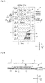
- double-headed arrows lines A, B and C are orthogonal to each other and show a longitudinal direction, a transverse direction and a thickness direction, respectively, of a pad-shaped absorbent article 1.
- the article 1 has a liquid permeable top sheet 2, a bottom sheet 3, which is either liquid permeable or liquid resistant or liquid impermeable, and superabsorbent polymer particles (hereinafter referred to as "SAP") 4.
- SAP 4 can be any suitable material known to those skilled in the art or to be developed in the future.
- a preferable one is a sodium polyacrylate, which is insoluble in water, absorbs more than at least ten times as much water as its own mass.
- the article 1 includes a plurality of absorbing areas 6 and sealing areas 7 outside the absorbing areas 6.
- the absorbing areas 6 extend in the transverse direction B and are arranged at predetermined intervals in the longitudinal direction A orthogonal to the transverse direction B.
- the top sheet 2 and the bottom sheet 3 are spaced apart (e.g., substantially free of direct attachment) and SAP 4 sandwiched between those sheets 2 and 3 are bonded to the bottom sheet 3.
- the top sheet 2 is bonded to the bottom sheet 3.
- the term "liquid impermeable" with respect to the bottom sheet 3 means that liquid to be absorbed by the absorbent article cannot permeate through the bottom sheet 3.
- any of liquid permeable materials, or liquid resistant materials or liquid impermeable materials may be used for the bottom sheet 3.
- Fig.2 the diameters of SAP 4 are shown on an exaggerated scale in order to show clearly the presence of SAP 4, which will be described hereunder.
- the absorbing areas 6 are surrounded by the sealing areas 7 including SAP 4 as an absorbent material, defining an existent area of SAP 4 of a required mass per unit area.
- a mass of SAP 4 from about 30 to about 300 g/m 2 , or more preferably, from about 40 to about 280 g/m 2 , is bonded to the bottom sheet 3 with the hot melt adhesive 11, which are uniformly coated to the entire surface of the bottom sheet 3.
- the absorbing areas 6 can also accommodate, in some embodiments, some SAP 4 which are not bonded to the bottom sheet 3.
- the upper limit of the total mass of SAP 4 which the absorbing areas 6 can accommodate between the top sheet 2 and the bottom sheet 3 is about 300 g/m 2 to about 500 g/m 2 , preferably about 400g/m 2 . It is preferable that the top sheet 2 and the bottom sheet 3 are not bonded to each other in the absorbing areas 6. However, in the production process of the article 1(see Figs. 3 , 4 ), the upper sheet 2, though not intended, may be bonded to the bottom sheet 3 in some very small spots.
- the sealing areas 7 are defined along the periphery of each absorbing area 6 to prevent SAP 4 from escaping out of each absorbing area 6, as it may happen when SAP 4 in the absorbing areas 6 are not bonded to the bottom sheet 3 with the hot melt adhesive 11 and are left in a movable state.
- the sealing areas 7 are substantially non-liquid absorbent and are substantially free of SAP 4, although SAP 4 up to about 20 g/ m 2 may be unintendedly incorporated in the sealing areas 7 during production of the article 1.
- the top sheet 2 and the bottom sheet 3 are bonded together with the hot melt adhesive 12, and/or other adhesives. Welding the top sheet 2 and the bottom sheet 3 both of which are already bonded together with the hot melt adhesive 12 may increase peel strength between the sheets 2 and 3.
- the top sheet 2 and the bottom sheet 3 in the sealing areas 7 are intended not to be peeled off in use of the article 1.
- the hot melt adhesive 11 and a second hot melt adhesive 102 (See Fig. 4 ) which will be described later are coated together so as to overlap in the sealing areas 7 and provide the hot melt adhesive 12.
- the top sheet 2 and the bottom sheet 3 are bonded together with the hot melt adhesive 12.
- Any hot melt adhesives known in the art or to be developed in the future may be used for the hot melt adhesives 11, 12 and 102.
- the article 1 is long in the longitudinal direction A and the absorbing areas 6 include eight (8) individual areas arranged along the longitudinal direction A, each of which is denoted by reference numerals from 6a to 6h and forming a liquid absorbing area containing SAP 4.
- Each of the individual absorbing areas 6a to 6h has a peripheral edge 61 defining its shape.
- the peripheral edges 61 of the absorbing areas 6 adjacent to each other in the longitudinal direction A include opposite edges 62 facing each other in the longitudinal direction A and extending laterally in the transverse direction B.
- the opposite edges 62 facing each other in the longitudinal direction A and extending in the transverse direction B are denoted by reference numerals 62a and 62b.
- the opposite edges 62a and 62b are undulating in the transverse direction B, which is a lengthwise direction of the opposite edges 62a and 62b.
- the opposite edges 62a have crest portions 63a and trough portions 64a, respectively, and the opposite edges 62b have crest portions 63b and trough portions 64b, respectively.
- the distance between the opposite portions 63a and 63b is narrower than that between the opposite portions 64a and 64b.
- a distance of one pitch between a pair of the portions 63b and a distance of one pitch between a pair of the portions 64a are almost the same, and a distance of one pitch between a pair of the portions 64a and a distance of one pitch between a pair of the portions 64b are almost the same.
- the sealing area 7 has three portions, i.e., side edge portions 7a positioned on both sides of the article 1 extending in the longitudinal direction A, end portions 7b positioned at both ends of the article 1 and extending in the transverse direction B, and intermediate portions 7c positioned between the absorbing areas 6 adjacent to each other in the longitudinal direction A and extending in the transverse direction B.
- each of the intermediate portions 7c is positioned between the opposite edges 62 of the absorbing areas 6 adjacent to each other in the longitudinal direction A and has narrow parts 22 and wide parts 23 measured in the longitudinal direction A.
- the article 1 is applied as an absorbent member for a disposable diaper or as a urine absorbing pad for an incontinence garment, the article 1 is placed on the diaper or the garment in such a manner that the longitudinal direction A of the articles is in line with the front and rear direction of the diaper or the garment and the central portion of the article 1 is laid just over the crotch region of the diaper or the garment.
- the top sheet 2 is made of a liquid permeable sheet with its surface facing toward the wearer's skin.
- the article 1 will provide the diaper (or garment) with one or more various advantages. For example, urine discharged from the wearer will permeate through the top sheet 2 and be absorbed and contained by SAP 4 in the absorbing areas 6 of the article 1 so as not to flow into the diaper.
- the bonding of SAP 4 to the bottom sheet 3 made of a liquid impermeable sheet and/or a liquid resistant sheet will keep SAP 4 in a uniform distribution, without uneven conglomeration of SAP 4, within the absorbing areas 6 positioned in the wearer's crotch region regardless of the wearer's various postures. Therefore, the article 1 will provide the diaper with a feature that the urine permeates through a broad area of the top sheet 2 and is absorbed and contained over a broad area of each of the absorbing areas 6.
- the article 1 will not press the wearer's skin hard by a locally increased thickness of the article 1 brought about by an uneven distribution of SAP 4 within the absorbing areas 6.
- the hot melt adhesive 11 will not decrease the permeability of the top sheet 2.
- SAP 4 bonded to the bottom sheet 3 will prevent the top sheet 2 from contacting or being bonded to the bottom sheet 3, to which the hot melt adhesive 11 is coated, and prevent the article 1 from having stiffness brought by the bondage of the top sheet 2 to the bottom sheet 3.
- a plurality of the intermediate portions 7c will help to make the article 1 positioned in the crotch region of the diaper deform flexibly in the longitudinal direction A.
- each intermediate portion 7c as measured in the longitudinal direction A is in a range from about 2 to about 15 mm at the narrow parts 22 and in a range from about 5 to about 20 mm at the wide parts 23.
- the difference in width (W) between the narrow parts 22 and the wide parts 23 is at least 3 mm.
- liquid permeable nonwoven fabrics made of thermoplastic synthetic fibers treated with hydrophilic agents such as an SMS (spunbond-meltblown-spunbond) nonwoven fabric made of polypropylene fibers treated with hydrophilic agents may be used.
- SMS nonwoven fabrics there is a sheet material having a basis mass of about 10 to about 12 g/m 2 , which includes a melt blown nonwoven fabric with a basis mass of about 0.5 to about 2.0 g/m 2 interposed between two layers of a spun bond nonwoven fabric with a basis mass of about 4 to about 5 g/m 2 .
- Liquid impermeable or liquid resistant nonwoven fabrics made of hydrophobic thermoplastic synthetic fibers are applicable to the bottom sheet 3.
- sheet materials made of liquid resistant SMS non-fabrics with a basis mass of about 10 to about 13 g/m 2 composed of a melt blown fabric with a basis mass of about 0.5 to about 2 g/m 2 interposed between two layers of a spun bond nonwoven fabric made of polypropylene fibers with a basis mass of about 4 to about 6 g/m 2 is applicable.
- liquid impermeable sheet members such as a plastic film made from polyethylene with a thickness of about 0.01 to about 0.03 mm, or liquid impermeable sheet members such as a laminate of a liquid permeable or liquid resistant nonwoven fabric made of thermoplastic synthetic fibers and a liquid impermeable plastic film are applicable.
- SAP 4 are bonded to the nonwoven fabric laid inside the article 1 and the liquid impermeable plastic film is laid outside the article 1 in order to prevent bodily fluid from leaking through the fiber interstices of the nonwoven fabric.
- SAP 4 with a single absorption speed or a combination of various absorption speeds may be available for the article 1.
- SAP 4 with an absorption speed of 30 seconds measured according to the VORTEX method specified by JIS K 7224 may be available with a basis mass of up to about 400 g/m 2 .
- the quantity of SAP 4 to be bonded is controlled according to the extent of the area of each absorbing areas 6 or application modes of the article 1.
- ingredients in SAP 4 that may elute when contacted with urine are included as little as possible. The ingredients eluted from the SAP 4 when contacted with urine may increase viscosity of the urine and may create a discomfort feeling to the wearer, if the urine contacts with the wearer's skin.
- the hot melt adhesive 11 is coated to the bottom sheet 3 in the absorbing areas 6 in order to bond SAP 4 to the bottom sheet 3, but in some occasions, the hot melt adhesive 11 may be coated to the sealing areas 7 in the bottom sheet 3.
- the hot melt adhesive 11 is coated uniformly to the inner surface 3a of the bottom sheet 3 with a basis mass of about 1 to about 12 g/m 2 . It is preferable that the basis mass of the hot melt adhesive 11 is as low as possible, so that SAP 4, which are to be bonded to the bottom sheet 3 in the absorbing areas 6, are not completely covered with the hot melt adhesive 11.
- the hot melt adhesive 11 may be coated to the bottom sheet 3 intermittently, for instance, in a dotted pattern or a bead-like pattern, or may be uniformly covering the entire area of the absorbing areas 6. In any case, it is preferable to provide a condition for liquid, such as urine discharged, to be quickly absorbed.
- the surfaces of SAP 4 facing the inner surface 3a of the bottom sheet 3 are covered with the hot melt adhesive 11 and bonded to the bottom sheet 3, while the surfaces of SAP 4 facing the inner surface 2b (see Fig. 2 ) of the top sheet 2 are not covered with the hot melt adhesive 11.
- the hot melt adhesive 12 is formed by additionally coating a second hot melt adhesive 102 (in Fig. 4 which will be described hereunder) with a basis mass of about 5 to about 30 g/m 2 to the bottom sheet 3 in the sealing areas 7 which is already coated with the hot melt adhesive 11.
- a second hot melt adhesive 102 in Fig. 4 which will be described hereunder
- the hot melt adhesive 11 covering the surface of SAP 4 may be avoided.
- the hot melt adhesive 12 for sealing will contribute to prevent the separation of the two sheets 2, 3.
- the hot melt adhesive 12 may be of the same materials or different materials, provided that the adhesives are bonded well to each other.
- the hot melt adhesive 11 coated to the sealing areas 7 has a sufficient bonding strength to prevent a separation of the two sheets 2, 3 in use, the hot melt adhesive 102 is not required. In this case, the basis mass of the hot melt adhesive will be the same in the absorbing areas 6 and the sealing areas 7.
- Plastic films instead of nonwoven fabrics, may be used for the bottom sheet 3.
- more hot melt adhesive 11 may be required in order to bond SAP 4 to the plastic film.
- more surface area of SAP 4 tends to be covered with the hot melt adhesive 11.
- each absorbing area 6 in the longitudinal direction A and the transverse direction B in other words, the dimensions of each individual area (e.g., any of individual areas 6a-6h) in the longitudinal direction A and the transverse direction B in Fig. 1 may be suitably decided according to the size of the diaper.
- the dimensions for each individual absorbing area can be in a range from about 25 to about 100 mm for the longitudinal direction A and in a range from about 150 to about 250 mm for the transverse direction B, and the number of the absorbing areas 6 are preferably from about 5 to about 15.
- the width (in the transverse direction B) of the side edge portion 7a and the width (in the longitudinal direction A) of the end portion 7b of the sealing area 7 are preferably in a range from about 5 to about 30 mm.
- the intermediate portions 7c of the sealing areas 7 occupying the area between the absorbing areas 6 adjacent to each other may serve as a guiding path of urine in the transverse direction B.
- the guiding path has the narrow part 22 and wide part 23, so the urine flowing into the wide part 23 through the narrow part 22 will flow not only in the transverse direction B but also in the longitudinal direction A as if it is spreading.
- the width of the urine path is reduced, so that the urine will not flow in the transverse direction B fast enough to reach the side edge portion 7a in the sealing area 7.
- the flowing speed of the urine is decreased and leakage of the urine from the side area of the article 1 may be reduced or prevented.
- the contours of the opposite edges 62 are not straight lines in the transverse direction B, but curved lines, so that, compared with a situation where the opposite edges 62 extend in straight lines in the transverse direction B, SAP 4 kept in individual absorbing areas 6 have more opportunities to encounter with the urine, making the article 1 more effective to absorb and contain the urine.
- the distance of one pitch between a pair of the portions 63a and the distance of one pitch between a pair of the portions 63b are preferably in a range from about 10 to about 50 mm in the transverse direction B, and both portions 63a, 63b are cooperatively defining the narrow part 22.
- the swollen SAP 4 may move within the absorbing areas 6 in the transverse direction B and, if collected at one or both of the side edges 65 of the absorbing areas 6, may locally increase the thickness of the absorbing areas 6 and may eventually pressing the wearer's skin.
- both side edges 65 of the individual area 6b of the absorbing areas 6 are denoted by a reference numeral 65b and both side edges in another individual area 6c of the absorbing areas 6 is denoted by a reference numeral 65c.
- Fig.3 and Fig.4 show a part of a production line of the article 1 and an enlarged view of a suction drum 130 on the production line, respectively.
- a first web 131 which is destined to define the top sheet 2
- SAP applicator 136 located above the suction drum 130 feeds SAP 4 onto the surface of the first web 131, which is in close contact with the outer surface 135 of the suction drum 130 by a suction force exerted inwardly of the suction drum 130 and by a pressing force from a guide roll 141.
- a second web 132 which is a continuous material of the bottom sheet 3, is continuously fed to the outer surface 135 of the suction drum 130 through guide rolls 142 from the left side of this drawing.
- One side of the second web 132 is coated with a first hot melt adhesive 101 supplied continuously from a first coater 121 located at a position upstream from the suction drum 130.
- a second hot melt adhesive 102 is coated to the surface of the web 132, which is already coated with the first hot melt adhesive 101, by a second coater 122 located at a position downstream from the first coater 121.
- the first web 131 fed with SAP 4 and the second web 132 coated with the first and the second hot melt adhesives 101, 102 are joined together on the outer surface 135 of the suction drum 130 and bonded to form a composite web 137.
- the composite web 137 is cut into a size of the article 1 by a cutting machine 138 at predetermined intervals.
- a portion of the first hot melt adhesive 101 is destined to define the hot melt adhesive 11 in the article 1, and another portion of the first hot melt adhesive 101 cooperates with the second hot melt adhesive 102 to provide the hot melt adhesive 12 for sealing. Details of the production process where the composite web 137 is formed are illustrated in Fig.4 .
- Fig. 4 illustrates cross sectional views of the first web 131 and the second web 132 both of which are joined together to form the composite web 137.
- a plurality of concave regions 151 are arranged circumferentially on the outer surface 135 of the suction drum 130.
- Each of the concave regions 151 in a plan view corresponds to the individual absorbing areas of the absorbing areas 6 arranged in the longitudinal direction A as shown in Fig.1 .
- the depth of the concave region 151 is configured to let each concave region 151 have a volume large enough to deposit a quantity of one-time feed of SAP 4 fed intermittently from the polymer SAP applicator 136.
- the first web 131 in contact with the outer surface 135 of the suction drum 130 is deformed by the suction force of the suction drum 130 working inwardly so as to conform to the inner shape of the concave region 151.
- SAP 4 fed from SAP applicator 136 is deposited in the deformed portion of the first web 131.
- a convex region 135a is formed between the adjacent concave regions 151 on the outer surface 135.
- the composite web 137 After having left from the suction drum 130 in the machine direction MD, the composite web 137 is compressed by a pair of second press rolls 144 ( Fig. 3 ), making SAP 4 contacted with the first hot melt adhesive 101 and bonding SAP 4 to the second web 132 with the first hot melt adhesive 101.
- the composite web 137 advances to a clearance between the pair of the second press rolls 144 at a slanted angle against the MD direction shown with a horizontal arrow line, but preferably the composite web 137 is conveyed into the clearance between the pair of the second press rolls 144 almost horizontally to make sure a horizontally uniform distribution of SAP 4 within a space between the first web 131 and the second web 132.
- the first hot melt adhesive 101 can be coated uniformly or intermittently either in the longitudinal direction A or in the transverse direction B of each of the absorbing areas 6 and the sealing areas 7, or can be coated continuously at least in either of the longitudinal direction A or the transverse direction B of the article 1. Therefore, there are no special requirements for the selection of the first coater 121 for the first hot melt adhesive 101, and the same applies to the second coater 122 for the second hot melt adhesive 102. It is preferable that the hot melt adhesive 11 in the absorbing areas 6 and the hot melt adhesive 12 in the sealing area 7 are coated in the article 1 in such a manner that each of the adhesives 11, 12 is contiguous, or the adhesives 11, 12 are positioned within a distance of less than 5 mm.
- SAP 4 will also be pervading through the entire area of each absorbing area 6 as well.
- SAP 4 can be aligned just inside the opposite edges 62 and distributed uniformly along the opposite edges 62 of each absorbing area 6. It is preferable that SAP 4 is distributed to cover almost the entire area of the inner surface 3a of the bottom sheet 3 in each absorbing areas 6, so that SAP 4 can prevent the top sheet 2 from being bonded to the bottom sheet 3 with the hot melt adhesive 11 in the absorbing areas 6.
- SAP 4 are bonded to the inner surface 3a of the bottom sheet 3 in the absorbing areas 6. Even if, however, some of SAP 4 are not bonded to the bottom sheet 3 and free to move in a space between the bottom sheet 3 and the top sheet 2 of the absorbing areas 6, one or more of the advantages and/or the objectives disclosed herein may be achieved.
- the top sheet 2 and the bottom sheet 3, if made of nonwoven fabrics have a structure that SAP 4 will not easily enter the fiber interstices of the nonwoven fabrics or pass through the interstices.
- the nonwoven fabrics for the top sheet 2 or the bottom sheet 3 are selected from such nonwoven fabrics which do not allow SAP 4 to enter the fiber interstices of the nonwoven fabrics when SAP 4 are dispersed over the nonwoven fabrics which are under a vibration.
- the shape of each of the sealing areas 7 may be changed so as to divide each of the individual areas (e.g., 6a-6h) into two or more sub-areas arranged intermittently in the transverse direction B.
- SAP 4 blended with a second superabsorbent polymer particles having a different absorption speed from that of SAP 4 in the absorbing areas 6.
- SAP 4 bonded to the bottom sheet 3 having an absorption speed AS 1 of 3 seconds measured by the VORTEX method and the second superabsorbent polymer particles having an absorption speed AS 2 of 30 seconds measured by the VORTEX method can be used together.
- the second superabsorbent polymer particles can be bonded to the upper sheet 2 with a third hot melt adhesive (not shown) in the absorbing areas 6, or can be bonded to neither of the top sheet 2 nor the bottom sheet 3 and left in the absorbing areas 6 in a freely movable condition.
- SAP 4 with a faster absorption speed AS 1 can be located near the bottom sheet 3 and the second superabsorbent polymer particles with a slower absorption speed AS 2 can be located adjacent to the top sheet 2 in the article 1.
- AS 1 absorption speed
- AS 2 absorption speed
- the urine discharged in the beginning may be absorbed by SAP 4 located far from the wearer's skin and retained there apart from the skin before gel blocks are formed by the second absorbent polymer particles, and the urine discharged afterward can be absorbed by the second superabsorbent polymer particles located adjacent to the wearer's skin, so that the wearer of the diaper having this article 1 may be relieved of an uncomfortable wearing condition brought by dampness of the article 1.
- the combined basis mass of SAP 4 and the second superabsorbent polymer particles in the absorbing areas 6 does not exceed about 400 g/m 2 .
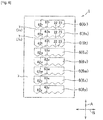
- Fig.5 is a plan view similar to Fig. 1 (but without a partially cut away portion), and shows the article 1 in accordance with an example not being part of the invention.
- the absorbing areas 6 in the article 1 in Fig.5 have individual absorbing areas 6i, 6j, 6k, 61 similar in shape to the individual areas 6a to 6h of the absorbing areas 6 in Fig.1 , and individual absorbing areas 6m, 6n, 6p, 6q having rectangular shapes.
- the individual absorbing areas 6i, 6j, 6k, 61 respectively have opposite wavy edges 62i, 62j, 62k, 621 extending in the transverse direction B.
- the individual absorbing areas 6m, 6n, 6p, 6q respectively have opposite straight edges 62m, 62n, 62p, 62q extending in the transverse direction B.
- the narrow part 22 and the wide part 23 are formed in the intermediate portions 7c of the sealing areas 7, the narrow part 22 and the wide part 23 are formed.
- the article 1 of this structure also works in a manner similar to that of the article 1 in Fig.1 .
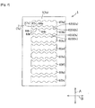
- Fig.6 is a plan view of the article 1, in accordance with another example not being part of the invention, similar to that in Fig. 5 , but all of the individual areas 6r, 6s, 6t, 6u, 6v, 6w, 6x, 6y of the absorbing areas 6 are in the same shape.
- One of the opposite edges 62 is straight and denoted by 62r, 62s, 62t, 62u, 62v, 62w, 62x, 62y corresponding to each of the individual areas, while the other of the opposite edges 62 is wavy and denoted by 63r, 63s, 63t, 63u, 63v, 63w, 63x, 63y which extend in the transverse direction B.
- This article 1 also has the narrow part 22 and the wide part 23 in the intermediate zones 7c.
- the article 1 of this structure also works in a manner similar to those of the articles 1 in Fig.1 and Fix.5.
- Fig.7 is a plan view similar to Fig. 1 (but without a partially cut away portion), and shows the article 1 in accordance with another example not being part of the invention.
- the article 1 in Fig. 7 has the individual areas of the absorbing areas 6, which are denoted by reference numerals 6a to 6h.
- Each of the individual areas 6a to 6h has opposite edges 62.
- Each of the opposite edges 62 extends in the transverse direction B in a wavy line, having the portions 63 and 64 on the opposite edges 62.
- the crest portion 63 of one individual area faces the trough portion 64 of the other individual area, likewise, the trough portion 64 of the one individual area faces the crest portion 63 of the other individual area.
- the intermediate portions 7c of the sealing area 7 located between the opposite edges 62 of the adjacent individual areas extend respectively in the transverse direction B in wavy lines.
- the situations described above will be described hereunder with the individual absorbing areas 6a and 6b of the absorbing areas 6.
- the absorbing areas 6 have the individual absorbing area 6a which has the opposite edges 62a, on at least one of which are positioned the crest portions 63a and the trough portions 64a.
- the absorbing areas 6 have similarly the individual absorbing areas 6b which has opposite edges 62b, on at least one of which are positioned the crest portions 63b and a trough portions 64b.
- the crest portions 63a on the opposite edge line 62a faces the trough portions 64b on the other opposite edge line 62b
- the trough portions 64a on the opposite edge line 62a faces the crest portion 63b on the other opposite edge 62b.
- the article 1 having such opposite edges 62 as exemplified by the opposite edges 62a and 62b shown in Fig.7 has the intermediate portions 7c waving in the sealing areas 7. Owing to the waving intermediate portions 7c, the urine discharged will not flow quickly in the transverse direction B, and the length of the path for the urine to flow will be extended compared to that of a straight line. Therefore, the urine will have more opportunities to contact with SAP 4, and thus sideway leakage of urine from the diaper will be reduced or prevented.
- the opposite edges 62 will contribute to prevent (or reduce the likelihood of) SAP 4 in such a state from gathering to one side 65 (see Fig.1 ) of the absorbing area 6 and help to disperse SAP 4 in a broader area in the absorbing areas 6.
- the application of the article 1 is not limited to a disposable diaper, but to any product where liquid absorbency is desirable.
- the article 1 may be applicable to a urine absorbent pad to be coupled with a diaper or a diaper cover, or a urine absorbent pad to be coupled with an underwear or a garment for incontinent persons.
- the article 1 is also applicable to wipes which are used for absorbing liquid such as waste water, or other water absorbent articles.
- liquid permeable or liquid impermeable or liquid resistant sheets may be used for the bottom sheet 3 of the article 1.
- the sheet members are sealed to each other in sealing areas, while in the absorbing areas, the superabsorbent polymer particles located between the sheet members will serve to prevent the sheet members from being directly bonded to each other. Accordingly, a problem of decrease in flexibility of the absorbent article will be solved and the absorbent article will be flexible.
- the superabsorbent polymer particles are bonded to either one of the opposed sheet members in the absorbing areas, so that the superabsorbent polymer particles may be uniformly distributed within the absorbing areas independent of the wearer's postures of the absorbent article.
- At least one of the opposite edges in the absorbing areas is defined in the wavy line having the crest and trough portions, so that even if some of the superabsorbent polymer particles are released from bonded states in the absorbing areas, the polymer particles will not move freely along one of the opposite edges toward the first direction due to the crest and trough patterns.
Landscapes
- Health & Medical Sciences (AREA)
- Engineering & Computer Science (AREA)
- Life Sciences & Earth Sciences (AREA)
- Biomedical Technology (AREA)
- Heart & Thoracic Surgery (AREA)
- Vascular Medicine (AREA)
- Epidemiology (AREA)
- Animal Behavior & Ethology (AREA)
- General Health & Medical Sciences (AREA)
- Public Health (AREA)
- Veterinary Medicine (AREA)
- Manufacturing & Machinery (AREA)
- Absorbent Articles And Supports Therefor (AREA)
Description
- The present disclosure relates to absorbent articles, and more specifically, to absorbent articles for bodily fluid absorbent wearing articles such as disposable diapers or disposable wipes.
- There are known absorbent articles including superabsorbent polymer particles interposed between two sheet members, at least one of which is liquid permeable.
- For example,
JP 1993-38350 A -
JP 3732320 B -
JP 2009-131510 A -
- PTL 1:
JP 1993-38350 A - PTL 2:
JP 3732320 B - PTL 3:
JP 2009-131510 A - The inventors have recognized that, the absorbent sheet, disclosed in PTL 1, including two absorbent sheet members and superabsorbent polymer particles interposed between these sheet members, which are bonded together with adhesives, may become less flexible because the superabsorbent polymer particles are uniformly interposed over the entirety between the absorbent sheet members.
- The inventors have further recognized that in the absorbent sheet disclosed in
PTL 3, the superabsorbent polymer particles relatively freely move before absorbing liquid, so that when the wearing article or the absorbent sheet are used for a disposable diaper, for example, the diaper may not be able to effectively absorb bodily fluid such as urine depending upon the wearer's postures. -
EP 1293187 discloses a thin water-absorbent sheet, used in disposable articles for retaining water or body fluids, comprising a water-absorbent resin powder bonded to a non-woven fabric by a hot-melt adhesive. - According to an aspect of the present invention, there is provided an absorbent article according to claim 1.
-
- [
fig.1]Fig. 1 is a partially cutaway plan view of an absorbent article in accordance with some embodiments. - [
fig.2]Fig. 2 is a cross sectional view taken along line II-II inFig.1 . - [
fig.3]Fig. 3 is an example of a production line for the absorbent article. - [
fig.4]Fig. 4 is an enlarged view of a portion of the production line inFig.3 . - [
fig.5]Fig. 5 is a view similar toFig.1 showing an example not being part of the present invention. - [
fig.6]Fig. 6 is a view similar toFig.5 showing an example not being part of the present invention. - [
fig.7]Fig. 7 is a view similar toFig.1 showing another example not being part of the present invention. - With reference to the drawings attached, absorbent articles in accordance with some embodiments of the present invention will be described in detail hereunder.
- Referring to
Fig.1 and Fig.2 , double-headed arrows lines A, B and C are orthogonal to each other and show a longitudinal direction, a transverse direction and a thickness direction, respectively, of a pad-shaped absorbent article 1. In these figures, the article 1 has a liquid permeabletop sheet 2, abottom sheet 3, which is either liquid permeable or liquid resistant or liquid impermeable, and superabsorbent polymer particles (hereinafter referred to as "SAP") 4. SAP 4 can be any suitable material known to those skilled in the art or to be developed in the future. A preferable one is a sodium polyacrylate, which is insoluble in water, absorbs more than at least ten times as much water as its own mass. The article 1 includes a plurality of absorbingareas 6 andsealing areas 7 outside the absorbingareas 6. The absorbingareas 6 extend in the transverse direction B and are arranged at predetermined intervals in the longitudinal direction A orthogonal to the transverse direction B. In the absorbingareas 6, thetop sheet 2 and thebottom sheet 3 are spaced apart (e.g., substantially free of direct attachment) andSAP 4 sandwiched between thosesheets bottom sheet 3. In thesealing areas 7, thetop sheet 2 is bonded to thebottom sheet 3. As used herein, the term "liquid impermeable" with respect to thebottom sheet 3 means that liquid to be absorbed by the absorbent article cannot permeate through thebottom sheet 3. Depending on the situations of actual applications or usages or conditions in production processes of the article 1, any of liquid permeable materials, or liquid resistant materials or liquid impermeable materials may be used for thebottom sheet 3. InFig.2 , the diameters ofSAP 4 are shown on an exaggerated scale in order to show clearly the presence ofSAP 4, which will be described hereunder. - The absorbing
areas 6 are surrounded by thesealing areas 7 includingSAP 4 as an absorbent material, defining an existent area ofSAP 4 of a required mass per unit area. In the absorbingareas 6, a mass ofSAP 4 from about 30 to about 300 g/m2, or more preferably, from about 40 to about 280 g/m2, is bonded to thebottom sheet 3 with thehot melt adhesive 11, which are uniformly coated to the entire surface of thebottom sheet 3. The absorbingareas 6 can also accommodate, in some embodiments, someSAP 4 which are not bonded to thebottom sheet 3. The upper limit of the total mass ofSAP 4 which the absorbingareas 6 can accommodate between thetop sheet 2 and thebottom sheet 3 is about 300 g/m2 to about 500 g/m2, preferably about 400g/m2. It is preferable that thetop sheet 2 and thebottom sheet 3 are not bonded to each other in the absorbingareas 6. However, in the production process of the article 1(seeFigs. 3 ,4 ), theupper sheet 2, though not intended, may be bonded to thebottom sheet 3 in some very small spots. - The
sealing areas 7 are defined along the periphery of each absorbingarea 6 to preventSAP 4 from escaping out of eachabsorbing area 6, as it may happen whenSAP 4 in the absorbingareas 6 are not bonded to thebottom sheet 3 with thehot melt adhesive 11 and are left in a movable state. Thesealing areas 7 are substantially non-liquid absorbent and are substantially free ofSAP 4, although SAP 4 up to about 20 g/ m2 may be unintendedly incorporated in thesealing areas 7 during production of the article 1. In thesealing areas 7, thetop sheet 2 and thebottom sheet 3 are bonded together with the hot melt adhesive 12, and/or other adhesives. Welding thetop sheet 2 and thebottom sheet 3 both of which are already bonded together with thehot melt adhesive 12 may increase peel strength between thesheets top sheet 2 and thebottom sheet 3 in thesealing areas 7 are intended not to be peeled off in use of the article 1. In the article 1 ofFig.2 , thehot melt adhesive 11 and a second hot melt adhesive 102 (SeeFig. 4 ) which will be described later are coated together so as to overlap in thesealing areas 7 and provide thehot melt adhesive 12. Thetop sheet 2 and thebottom sheet 3 are bonded together with thehot melt adhesive 12. Any hot melt adhesives known in the art or to be developed in the future may be used for thehot melt adhesives - The article 1 is long in the longitudinal direction A and the absorbing
areas 6 include eight (8) individual areas arranged along the longitudinal direction A, each of which is denoted by reference numerals from 6a to 6h and forming a liquid absorbingarea containing SAP 4. Each of the individual absorbingareas 6a to 6h has aperipheral edge 61 defining its shape. Theperipheral edges 61 of the absorbingareas 6 adjacent to each other in the longitudinal direction A includeopposite edges 62 facing each other in the longitudinal direction A and extending laterally in the transverse direction B. For example, inFig.1 in the peripheral edges of theabsorbing areas opposite edges 62 facing each other in the longitudinal direction A and extending in the transverse direction B are denoted byreference numerals opposite edges opposite edges opposite edges 62a havecrest portions 63a andtrough portions 64a, respectively, and theopposite edges 62b havecrest portions 63b andtrough portions 64b, respectively. In the longitudinal direction A, the distance between theopposite portions opposite portions portions 63b and a distance of one pitch between a pair of theportions 64a are almost the same, and a distance of one pitch between a pair of theportions 64a and a distance of one pitch between a pair of theportions 64b are almost the same. - The
sealing area 7 has three portions, i.e.,side edge portions 7a positioned on both sides of the article 1 extending in the longitudinal direction A,end portions 7b positioned at both ends of the article 1 and extending in the transverse direction B, andintermediate portions 7c positioned between theabsorbing areas 6 adjacent to each other in the longitudinal direction A and extending in the transverse direction B. In other words, each of theintermediate portions 7c is positioned between theopposite edges 62 of theabsorbing areas 6 adjacent to each other in the longitudinal direction A and hasnarrow parts 22 andwide parts 23 measured in the longitudinal direction A. - If the article 1 is applied as an absorbent member for a disposable diaper or as a urine absorbing pad for an incontinence garment, the article 1 is placed on the diaper or the garment in such a manner that the longitudinal direction A of the articles is in line with the front and rear direction of the diaper or the garment and the central portion of the article 1 is laid just over the crotch region of the diaper or the garment. The
top sheet 2 is made of a liquid permeable sheet with its surface facing toward the wearer's skin. - The article 1 will provide the diaper (or garment) with one or more various advantages. For example, urine discharged from the wearer will permeate through the
top sheet 2 and be absorbed and contained bySAP 4 in the absorbingareas 6 of the article 1 so as not to flow into the diaper. The bonding ofSAP 4 to thebottom sheet 3 made of a liquid impermeable sheet and/or a liquid resistant sheet will keepSAP 4 in a uniform distribution, without uneven conglomeration ofSAP 4, within the absorbingareas 6 positioned in the wearer's crotch region regardless of the wearer's various postures. Therefore, the article 1 will provide the diaper with a feature that the urine permeates through a broad area of thetop sheet 2 and is absorbed and contained over a broad area of each of the absorbingareas 6. In such a diaper, the article 1 will not press the wearer's skin hard by a locally increased thickness of the article 1 brought about by an uneven distribution ofSAP 4 within the absorbingareas 6. In the absorbingareas 6 where the hot melt adhesive 11 is coated to thebottom sheet 3, but not coated to thetop sheet 2, the hot melt adhesive 11 will not decrease the permeability of thetop sheet 2.SAP 4 bonded to thebottom sheet 3 will prevent thetop sheet 2 from contacting or being bonded to thebottom sheet 3, to which the hot melt adhesive 11 is coated, and prevent the article 1 from having stiffness brought by the bondage of thetop sheet 2 to thebottom sheet 3. A plurality of theintermediate portions 7c will help to make the article 1 positioned in the crotch region of the diaper deform flexibly in the longitudinal direction A. The width W of eachintermediate portion 7c as measured in the longitudinal direction A is in a range from about 2 to about 15 mm at thenarrow parts 22 and in a range from about 5 to about 20 mm at thewide parts 23. Preferably, the difference in width (W) between thenarrow parts 22 and thewide parts 23 is at least 3 mm. - According to an embodiment of the article 1, as the
top sheet 2,liquid permeable nonwoven fabrics made of thermoplastic synthetic fibers treated with hydrophilic agents, such as an SMS (spunbond-meltblown-spunbond) nonwoven fabric made of polypropylene fibers treated with hydrophilic agents may be used. As an example of such SMS nonwoven fabrics, there is a sheet material having a basis mass of about 10 to about 12 g/m2, which includes a melt blown nonwoven fabric with a basis mass of about 0.5 to about 2.0 g/m2 interposed between two layers of a spun bond nonwoven fabric with a basis mass of about 4 to about 5 g/m2. Liquid impermeable or liquid resistant nonwoven fabrics made of hydrophobic thermoplastic synthetic fibers are applicable to thebottom sheet 3. For example, sheet materials made of liquid resistant SMS non-fabrics with a basis mass of about 10 to about 13 g/m2 composed of a melt blown fabric with a basis mass of about 0.5 to about 2 g/m2 interposed between two layers of a spun bond nonwoven fabric made of polypropylene fibers with a basis mass of about 4 to about 6 g/m2 is applicable. In addition, for thebottom sheet 3, liquid impermeable sheet members such as a plastic film made from polyethylene with a thickness of about 0.01 to about 0.03 mm, or liquid impermeable sheet members such as a laminate of a liquid permeable or liquid resistant nonwoven fabric made of thermoplastic synthetic fibers and a liquid impermeable plastic film are applicable. In a preferable laminate,SAP 4 are bonded to the nonwoven fabric laid inside the article 1 and the liquid impermeable plastic film is laid outside the article 1 in order to prevent bodily fluid from leaking through the fiber interstices of the nonwoven fabric. - Different kinds of SAP have different liquid absorption speeds.
SAP 4 with a single absorption speed or a combination of various absorption speeds may be available for the article 1. For example,SAP 4 with an absorption speed of 30 seconds measured according to the VORTEX method specified by JIS K 7224 may be available with a basis mass of up to about 400 g/m2. It is preferable that the quantity ofSAP 4 to be bonded is controlled according to the extent of the area of each absorbingareas 6 or application modes of the article 1. In some embodiments ingredients inSAP 4 that may elute when contacted with urine are included as little as possible. The ingredients eluted from theSAP 4 when contacted with urine may increase viscosity of the urine and may create a discomfort feeling to the wearer, if the urine contacts with the wearer's skin. - The hot melt adhesive 11 is coated to the
bottom sheet 3 in the absorbingareas 6 in order to bondSAP 4 to thebottom sheet 3, but in some occasions, the hot melt adhesive 11 may be coated to thesealing areas 7 in thebottom sheet 3. According toFig.2 , for example, the hot melt adhesive 11 is coated uniformly to theinner surface 3a of thebottom sheet 3 with a basis mass of about 1 to about 12 g/m2. It is preferable that the basis mass of the hot melt adhesive 11 is as low as possible, so thatSAP 4, which are to be bonded to thebottom sheet 3 in the absorbingareas 6, are not completely covered with the hot melt adhesive 11. The hot melt adhesive 11 may be coated to thebottom sheet 3 intermittently, for instance, in a dotted pattern or a bead-like pattern, or may be uniformly covering the entire area of the absorbingareas 6. In any case, it is preferable to provide a condition for liquid, such as urine discharged, to be quickly absorbed. For that purpose, in some embodiments, the surfaces ofSAP 4 facing theinner surface 3a of thebottom sheet 3 are covered with the hot melt adhesive 11 and bonded to thebottom sheet 3, while the surfaces ofSAP 4 facing theinner surface 2b (seeFig. 2 ) of thetop sheet 2 are not covered with the hot melt adhesive 11. - The hot melt adhesive 12 is formed by additionally coating a second hot melt adhesive 102 (in
Fig. 4 which will be described hereunder) with a basis mass of about 5 to about 30 g/m2 to thebottom sheet 3 in thesealing areas 7 which is already coated with the hot melt adhesive 11. By controlling the basis mass of the hot melt adhesives in the absorbingareas 6 and thesealing areas 7 in this manner, certain situations in the absorbingareas 6 where the quantity of the liquid to be absorbed and/or the absorption speed ofSAP 4 are affected by the hot melt adhesive 11 covering the surface ofSAP 4 may be avoided. In thesealing areas 7, if the amount of the hot melt adhesive 11 is not enough to prevent a separation of thetop sheet 2 from thebottom sheet 3, e.g., in use, the hot melt adhesive 12 for sealing will contribute to prevent the separation of the twosheets SAP 4 not fixed to thebottom sheet 3 in the absorbingareas 6 from entering the sealingareas 7, it is preferable to coat the hot melt adhesive 12 up to the periphery of the absorbingareas 6 uniformly, or substantially continuously, to secure thetop sheet 2 to thebottom sheet 3. The hot melt adhesive 11 and the hot melt adhesive 12 may be of the same materials or different materials, provided that the adhesives are bonded well to each other. If the hot melt adhesive 11 coated to thesealing areas 7 has a sufficient bonding strength to prevent a separation of the twosheets areas 6 and thesealing areas 7. - Plastic films, instead of nonwoven fabrics, may be used for the
bottom sheet 3. However, on some occasions, more hot melt adhesive 11 may be required in order to bondSAP 4 to the plastic film. On that occasion, more surface area ofSAP 4 tends to be covered with the hot melt adhesive 11. - When the article 1 is applied to a diaper, the dimensions of each absorbing
area 6 in the longitudinal direction A and the transverse direction B, in other words, the dimensions of each individual area (e.g., any ofindividual areas 6a-6h) in the longitudinal direction A and the transverse direction B inFig. 1 may be suitably decided according to the size of the diaper. For instance, the dimensions for each individual absorbing area can be in a range from about 25 to about 100 mm for the longitudinal direction A and in a range from about 150 to about 250 mm for the transverse direction B, and the number of the absorbingareas 6 are preferably from about 5 to about 15. The width (in the transverse direction B) of theside edge portion 7a and the width (in the longitudinal direction A) of theend portion 7b of the sealingarea 7 are preferably in a range from about 5 to about 30 mm. - When the article 1 is applied to a diaper and urine is discharged to the article 1, the
intermediate portions 7c of the sealingareas 7 occupying the area between the absorbingareas 6 adjacent to each other may serve as a guiding path of urine in the transverse direction B. However, the guiding path has thenarrow part 22 andwide part 23, so the urine flowing into thewide part 23 through thenarrow part 22 will flow not only in the transverse direction B but also in the longitudinal direction A as if it is spreading. When the urine flows into thenarrow part 22 out of thewide part 23, the width of the urine path is reduced, so that the urine will not flow in the transverse direction B fast enough to reach theside edge portion 7a in thesealing area 7. By forming the liquid guiding path which is non-linear and/or has various widths as exemplarily described, the flowing speed of the urine is decreased and leakage of the urine from the side area of the article 1 may be reduced or prevented. In thewide part 23, the contours of theopposite edges 62 are not straight lines in the transverse direction B, but curved lines, so that, compared with a situation where theopposite edges 62 extend in straight lines in the transverse direction B,SAP 4 kept in individual absorbingareas 6 have more opportunities to encounter with the urine, making the article 1 more effective to absorb and contain the urine. The distance of one pitch between a pair of theportions 63a and the distance of one pitch between a pair of theportions 63b are preferably in a range from about 10 to about 50 mm in the transverse direction B, and bothportions narrow part 22. - In the absorbing
areas 6, some ofSAP 4 in a swollen state or in a gel-block state brought by the absorption of urine are not fixed to thebottom sheet 3 and will, on some occasions, move relatively freely within the absorbingareas 6. According to a wearer's posture of the diaper, theswollen SAP 4 may move within the absorbingareas 6 in the transverse direction B and, if collected at one or both of the side edges 65 of the absorbingareas 6, may locally increase the thickness of the absorbingareas 6 and may eventually pressing the wearer's skin. However, in the absorbingareas 6 where the contour ofopposite edge 62 is defined by a wavy line as shown inFig.1 someswollen SAP 4 which move in the transverse direction B along theopposite edges 62 may be stopped in the region 66 (seeFig.1 ), because theopposite edges 62 are curved toward the inside of the absorbingareas 6 in a convex pattern so as to make thewide part 23 in thesealing areas 7. Accordingly, even if the wearer is in a state of lying down on the wearer's side, this structure of the article 1 will prevent (or reduce the likelihood of)SAP 4 from moving toward either of the side edges 65 of the absorbingareas 6 and being collected thereat, assuring a uniform distribution ofSAP 4 within the absorbingareas 6, in use. InFig. 1 , both side edges 65 of theindividual area 6b of the absorbingareas 6 are denoted by areference numeral 65b and both side edges in anotherindividual area 6c of the absorbingareas 6 is denoted by areference numeral 65c. -
Fig.3 andFig.4 show a part of a production line of the article 1 and an enlarged view of asuction drum 130 on the production line, respectively. Referring toFig.3 , afirst web 131, which is destined to define thetop sheet 2, is continuously fed to theouter surface 135 of thesuction drum 130 from the right side of this drawing.SAP applicator 136 located above thesuction drum 130 feedsSAP 4 onto the surface of thefirst web 131, which is in close contact with theouter surface 135 of thesuction drum 130 by a suction force exerted inwardly of thesuction drum 130 and by a pressing force from aguide roll 141. Asecond web 132, which is a continuous material of thebottom sheet 3, is continuously fed to theouter surface 135 of thesuction drum 130 through guide rolls 142 from the left side of this drawing. One side of thesecond web 132 is coated with a first hot melt adhesive 101 supplied continuously from a first coater 121 located at a position upstream from thesuction drum 130. A second hot melt adhesive 102 is coated to the surface of theweb 132, which is already coated with the first hot melt adhesive 101, by a second coater 122 located at a position downstream from the first coater 121. Thefirst web 131 fed withSAP 4 and thesecond web 132 coated with the first and the secondhot melt adhesives outer surface 135 of thesuction drum 130 and bonded to form acomposite web 137. Thecomposite web 137 is cut into a size of the article 1 by a cuttingmachine 138 at predetermined intervals. A portion of the first hot melt adhesive 101 is destined to define the hot melt adhesive 11 in the article 1, and another portion of the first hot melt adhesive 101 cooperates with the second hot melt adhesive 102 to provide the hot melt adhesive 12 for sealing. Details of the production process where thecomposite web 137 is formed are illustrated inFig.4 . -
Fig. 4 illustrates cross sectional views of thefirst web 131 and thesecond web 132 both of which are joined together to form thecomposite web 137. A plurality ofconcave regions 151 are arranged circumferentially on theouter surface 135 of thesuction drum 130. Each of theconcave regions 151 in a plan view corresponds to the individual absorbing areas of the absorbingareas 6 arranged in the longitudinal direction A as shown inFig.1 . The depth of theconcave region 151 is configured to let eachconcave region 151 have a volume large enough to deposit a quantity of one-time feed ofSAP 4 fed intermittently from thepolymer SAP applicator 136. Thefirst web 131 in contact with theouter surface 135 of thesuction drum 130 is deformed by the suction force of thesuction drum 130 working inwardly so as to conform to the inner shape of theconcave region 151.SAP 4 fed fromSAP applicator 136 is deposited in the deformed portion of thefirst web 131. Between the adjacentconcave regions 151 on theouter surface 135, aconvex region 135a is formed. When thefirst web 131 and thesecond web 132 are joined together and run through between thefirst press roll 143 and theconvex region 135a of theouter surface 135, thefirst web 131 and thesecond web 132 are compressed by thefirst press roll 143 and theconvex region 135a, providing thecomposite web 137. After having left from thesuction drum 130 in the machine direction MD, thecomposite web 137 is compressed by a pair of second press rolls 144 (Fig. 3 ), makingSAP 4 contacted with the first hot melt adhesive 101 andbonding SAP 4 to thesecond web 132 with the first hot melt adhesive 101. Referring toFig.3 , thecomposite web 137 advances to a clearance between the pair of the second press rolls 144 at a slanted angle against the MD direction shown with a horizontal arrow line, but preferably thecomposite web 137 is conveyed into the clearance between the pair of the second press rolls 144 almost horizontally to make sure a horizontally uniform distribution ofSAP 4 within a space between thefirst web 131 and thesecond web 132. - In the article 1 formed in this manner, the first hot melt adhesive 101 can be coated uniformly or intermittently either in the longitudinal direction A or in the transverse direction B of each of the absorbing
areas 6 and thesealing areas 7, or can be coated continuously at least in either of the longitudinal direction A or the transverse direction B of the article 1. Therefore, there are no special requirements for the selection of the first coater 121 for the first hot melt adhesive 101, and the same applies to the second coater 122 for the second hot melt adhesive 102. It is preferable that the hot melt adhesive 11 in the absorbingareas 6 and the hot melt adhesive 12 in thesealing area 7 are coated in the article 1 in such a manner that each of theadhesives adhesives area 6 including its four corners of the absorbingarea 6,SAP 4 will also be pervading through the entire area of each absorbingarea 6 as well. For instance,SAP 4 can be aligned just inside theopposite edges 62 and distributed uniformly along theopposite edges 62 of each absorbingarea 6. It is preferable thatSAP 4 is distributed to cover almost the entire area of theinner surface 3a of thebottom sheet 3 in each absorbingareas 6, so thatSAP 4 can prevent thetop sheet 2 from being bonded to thebottom sheet 3 with the hot melt adhesive 11 in the absorbingareas 6. - It is also preferable that all of
SAP 4 are bonded to theinner surface 3a of thebottom sheet 3 in the absorbingareas 6. Even if, however, some ofSAP 4 are not bonded to thebottom sheet 3 and free to move in a space between thebottom sheet 3 and thetop sheet 2 of the absorbingareas 6, one or more of the advantages and/or the objectives disclosed herein may be achieved. In order to holdSAP 4 within the absorbingareas 6 in such a condition as described above, it is preferable that thetop sheet 2 and thebottom sheet 3, if made of nonwoven fabrics, have a structure that SAP 4 will not easily enter the fiber interstices of the nonwoven fabrics or pass through the interstices. Accordingly, the nonwoven fabrics for thetop sheet 2 or thebottom sheet 3 are selected from such nonwoven fabrics which do not allowSAP 4 to enter the fiber interstices of the nonwoven fabrics whenSAP 4 are dispersed over the nonwoven fabrics which are under a vibration. There are no specific requirements for a shape of the article 1 or a shape of the absorbingareas 6 or the number of the individual areas of the absorbingareas 6, so that suitable modifications in the shape and/or the number of the individual areas of the absorbingareas 6 will be allowed. For instance, the shape of each of the sealingareas 7 may be changed so as to divide each of the individual areas (e.g., 6a-6h) into two or more sub-areas arranged intermittently in the transverse direction B. - It is also possible to use
SAP 4 blended with a second superabsorbent polymer particles (not shown) having a different absorption speed from that ofSAP 4 in the absorbingareas 6. For instance,SAP 4 bonded to thebottom sheet 3 having an absorption speed AS1 of 3 seconds measured by the VORTEX method and the second superabsorbent polymer particles having an absorption speed AS2 of 30 seconds measured by the VORTEX method can be used together. The second superabsorbent polymer particles can be bonded to theupper sheet 2 with a third hot melt adhesive (not shown) in the absorbingareas 6, or can be bonded to neither of thetop sheet 2 nor thebottom sheet 3 and left in the absorbingareas 6 in a freely movable condition.SAP 4 with a faster absorption speed AS1 can be located near thebottom sheet 3 and the second superabsorbent polymer particles with a slower absorption speed AS2 can be located adjacent to thetop sheet 2 in the article 1. When the diaper having the article 1 described above is worn with thetop sheet 2 facing the wearer's skin, the urine discharged in the beginning may be absorbed bySAP 4 located far from the wearer's skin and retained there apart from the skin before gel blocks are formed by the second absorbent polymer particles, and the urine discharged afterward can be absorbed by the second superabsorbent polymer particles located adjacent to the wearer's skin, so that the wearer of the diaper having this article 1 may be relieved of an uncomfortable wearing condition brought by dampness of the article 1. Preferably, the combined basis mass ofSAP 4 and the second superabsorbent polymer particles in the absorbingareas 6 does not exceed about 400 g/m2. -
Fig.5 is a plan view similar toFig. 1 (but without a partially cut away portion), and shows the article 1 in accordance with an example not being part of the invention. The absorbingareas 6 in the article 1 inFig.5 haveindividual absorbing areas individual areas 6a to 6h of the absorbingareas 6 inFig.1 , andindividual absorbing areas individual absorbing areas wavy edges individual absorbing areas straight edges intermediate portions 7c of the sealingareas 7, thenarrow part 22 and thewide part 23 are formed. The article 1 of this structure also works in a manner similar to that of the article 1 inFig.1 . -
Fig.6 is a plan view of the article 1, in accordance with another example not being part of the invention, similar to that inFig. 5 , but all of theindividual areas areas 6 are in the same shape. One of theopposite edges 62 is straight and denoted by 62r, 62s, 62t, 62u, 62v, 62w, 62x, 62y corresponding to each of the individual areas, while the other of theopposite edges 62 is wavy and denoted by 63r, 63s, 63t, 63u, 63v, 63w, 63x, 63y which extend in the transverse direction B. This article 1 also has thenarrow part 22 and thewide part 23 in theintermediate zones 7c. The article 1 of this structure also works in a manner similar to those of the articles 1 inFig.1 and Fix.5. -
Fig.7 is a plan view similar toFig. 1 (but without a partially cut away portion), and shows the article 1 in accordance with another example not being part of the invention. The article 1 inFig. 7 has the individual areas of the absorbingareas 6, which are denoted byreference numerals 6a to 6h. Each of theindividual areas 6a to 6h has opposite edges 62. Each of theopposite edges 62 extends in the transverse direction B in a wavy line, having the portions 63 and 64 on the opposite edges 62. Between a pair of adjacent individual areas, the crest portion 63 of one individual area faces the trough portion 64 of the other individual area, likewise, the trough portion 64 of the one individual area faces the crest portion 63 of the other individual area. Theintermediate portions 7c of the sealingarea 7 located between theopposite edges 62 of the adjacent individual areas extend respectively in the transverse direction B in wavy lines. The situations described above will be described hereunder with theindividual absorbing areas areas 6. The absorbingareas 6 have the individual absorbingarea 6a which has theopposite edges 62a, on at least one of which are positioned thecrest portions 63a and thetrough portions 64a. The absorbingareas 6 have similarly theindividual absorbing areas 6b which hasopposite edges 62b, on at least one of which are positioned thecrest portions 63b and atrough portions 64b. Regarding theopposite edges crest portions 63a on theopposite edge line 62a faces thetrough portions 64b on the otheropposite edge line 62b, and thetrough portions 64a on theopposite edge line 62a faces thecrest portion 63b on the otheropposite edge 62b. - The article 1 having such
opposite edges 62 as exemplified by theopposite edges Fig.7 has theintermediate portions 7c waving in thesealing areas 7. Owing to the wavingintermediate portions 7c, the urine discharged will not flow quickly in the transverse direction B, and the length of the path for the urine to flow will be extended compared to that of a straight line. Therefore, the urine will have more opportunities to contact withSAP 4, and thus sideway leakage of urine from the diaper will be reduced or prevented. If there areSAP 4 which are in a state of being not bonded to thebottom sheet 3 or thetop sheet 2, and in a swollen or gel-blocking state, theopposite edges 62 will contribute to prevent (or reduce the likelihood of)SAP 4 in such a state from gathering to one side 65 (seeFig.1 ) of the absorbingarea 6 and help to disperseSAP 4 in a broader area in the absorbingareas 6. - The application of the article 1 is not limited to a disposable diaper, but to any product where liquid absorbency is desirable. For example, the article 1 may be applicable to a urine absorbent pad to be coupled with a diaper or a diaper cover, or a urine absorbent pad to be coupled with an underwear or a garment for incontinent persons. The article 1 is also applicable to wipes which are used for absorbing liquid such as waste water, or other water absorbent articles. When the article 1 is used as the wipes, liquid permeable or liquid impermeable or liquid resistant sheets may be used for the
bottom sheet 3 of the article 1. - (1) An aspect of the present invention may be arranged in at least the following features:
The absorbent article having a first direction and a second direction orthogonal to the first direction, includes:- two sheet members, at least one of which is liquid permeable; and superabsorbent polymer particles interposed between facing surfaces of the two sheet members; wherein
- one of the facing surfaces of the two sheet members is coated with a first hot melt adhesive;
- the superabsorbent polymer particles are bonded to the one of the facing surfaces with the first hot melt adhesive in absorbing areas extending in the second direction and arranged at predetermined intervals in the first direction;
- the facing surfaces of the two sheet members are further bonded to each other with a second hot melt adhesive in sealing areas outside the absorbing areas, and the sealing areas are substantially free of the superabsorbent polymer particles;
- the absorbing areas adjacent to each other in the first direction have opposite edges by intermediary of the sealing areas, and at least one of the opposite edges is defined by a wavy line having crest portions and trough portions in the second direction, wherein the crest and trough portions of one of the opposite edges of the absorbing areas adjacent to each other in the first direction respectively face the crest and trough portions of the other of the opposite edges of the absorbing areas adjacent to each other in the first direction.
- (2) The aspect of the present invention described in (1) may include at least the following embodiments:
- (i) Each of the two sheet members is liquid permeable.
- (ii) One of the two sheet members is liquid permeable and the other of the two sheet members is either liquid impermeable or liquid resistant,
and the superabsorbent polymer particles are bonded to the other of the two sheet members. - (iii) The two sheet members are a hydrophilic nonwoven fabric made of thermoplastic synthetic fibers.
- (iv) The liquid impermeable or liquid resistant sheet member is one of (a) a hydrophobic nonwoven fabric made of thermoplastic synthetic fibers and (b) a laminate of the hydrophobic nonwoven fabric and a liquid impermeable plastic film, and the superabsorbent polymer particles are bonded to the hydrophobic nonwoven fabric.
- (v) The first hot melt adhesive and the second hot melt adhesive are contiguous.
- (vi) The first hot melt adhesive and the second hot melt adhesive are adjacent to each other.
- (vii) The superabsorbent polymer particles have an absorption speed of AS1 and second absorbent polymer particles with a lower absorption speed of AS2 than AS1 are interposed between the two sheet members in the absorbing areas.
- (viii) The second superabsorbent polymer particles are bonded to the other one of the facing surfaces with a further hot melt adhesive.
- (ix) The second superabsorbent polymer particles are not bonded to either of the facing surfaces.
- (x) The first hot melt adhesive for bonding the superabsorbent polymer particles in the absorbing areas is the same as the second hot melt adhesive in the sealing areas.
- (xi) The first direction corresponds to a longitudinal direction of the article and the second direction corresponds to a transverse direction of the article.
- (3) Another aspect of the present invention may be arranged in at least the following features:
- An absorbent article having a first direction and a second direction orthogonal to the first direction, includes:
- two sheet members, at least one of which is liquid permeable; and superabsorbent polymer particles interposed between facing surfaces of the two sheet members; wherein
- the superabsorbent polymer particles are adhesively bonded to one of the facing surfaces in absorbing areas extending in the second direction and arranged at predetermined intervals in the first direction;
- the facing surfaces of the two sheet members are further adhesively bonded to each other in sealing areas outside the absorbing areas, and the sealing areas are substantially free of the superabsorbent polymer particles;
- the sealing areas include an intermediate portion positioned between the absorbing areas adjacent to each other in the first direction,
- the intermediate portion defining a guiding path for liquid discharged on the article in the second direction, the path being non-linear or having various widths for reducing a speed of the liquid flowing on the path.
- An absorbent article having a first direction and a second direction orthogonal to the first direction, includes:
- (4) The aspect of the present invention described in (3) includes at least the following embodiments:
- The liquid guiding path is defined by opposite edges of the absorbing areas adjacent to each other in the first direction, each of the opposite edges being a wavy line having at least one crest portion and at least one trough portion, and the crest and trough portions of one of the opposite edges respectively face the crest and trough portions of the other of the opposite edges.
- The described aspects and/or embodiments provide one or more of the following effects.
- In a pad-shaped absorbent article disclosed in the present invention, the sheet members are sealed to each other in sealing areas, while in the absorbing areas, the superabsorbent polymer particles located between the sheet members will serve to prevent the sheet members from being directly bonded to each other. Accordingly, a problem of decrease in flexibility of the absorbent article will be solved and the absorbent article will be flexible. The superabsorbent polymer particles are bonded to either one of the opposed sheet members in the absorbing areas, so that the superabsorbent polymer particles may be uniformly distributed within the absorbing areas independent of the wearer's postures of the absorbent article. At least one of the opposite edges in the absorbing areas is defined in the wavy line having the crest and trough portions, so that even if some of the superabsorbent polymer particles are released from bonded states in the absorbing areas, the polymer particles will not move freely along one of the opposite edges toward the first direction due to the crest and trough patterns.
Claims (12)
- An absorbent article having a first direction and a second direction orthogonal to the first direction, comprising:two sheet members, at least one of which is liquid permeable; andsuperabsorbent polymer particles interposed between facing surfaces of the two sheet members; whereinone of the facing surfaces of the two sheet members is coated with a first hot melt adhesive;the superabsorbent polymer particles are bonded to the one of the facing surfaces with the first hot melt adhesive in absorbing areas extending in the second direction and arranged at predetermined intervals in the first direction;the facing surfaces of the two sheet members are further bonded to each other with a second hot melt adhesive in sealing areas outside the absorbing areas, and the sealing areas are substantially free of the superabsorbent polymer particles;the absorbing areas adjacent to each other in the first direction have opposite edges by intermediary of the sealing areas, and at least one of the opposite edges is defined by a wavy line having crest portions and trough portions in the second direction;wherein the crest and trough portions of one of the opposite edges of the absorbing areas adjacent to each other in the first direction respectively face the crest and trough portions of the other of the opposite edges of the absorbing areas adjacent to each other in the first direction.
- The article defined claim 1 2, wherein each of the two sheet members is liquid permeable.
- The article defined by any one of claims 1 to 2, wherein one of the two sheet members is liquid permeable and the other of the two sheet members is either liquid impermeable or liquid resistant, and the superabsorbent polymer particles are bonded to the other of the two sheet members.
- The article defined by any one of claims 1 to 3, wherein the two sheet members are a hydrophilic nonwoven fabric made of thermoplastic synthetic fibers.
- The article defined by claim 3, wherein the liquid impermeable or liquid resistant sheet member is one of (a) a hydrophobic nonwoven fabric made of thermoplastic synthetic fibers and (b) a laminate of the hydrophobic nonwoven fabric and a liquid impermeable plastic film, and the superabsorbent polymer particles are bonded to the hydrophobic nonwoven fabric.
- The article defined by any one of claims 1 to 5, wherein the first hot melt adhesive and the second hot melt adhesive are contiguous.
- The article defined by any one of claims 1 to 5, wherein the first hot melt adhesive and the second hot melt adhesive are adjacent to each other.
- The article defined by any one of claims 1 to 7, wherein the superabsorbent polymer particles have an absorption speed of AS1 and second absorbent polymer particles with a lower absorption speed of AS2 than AS1 are interposed between the two sheet members in the absorbing areas.
- The article defined by claim 8, wherein the second superabsorbent polymer particles are bonded to the other one of the facing surfaces with a further hot melt adhesive.
- The article defined by claim 8 or 9, wherein the second superabsorbent polymer particles are not bonded to either of the facing surfaces.
- The article defined by any one of claims 6 to 10, wherein the first hot melt adhesive for bonding the superabsorbent polymer particles in the absorbing areas is the same as the second hot melt adhesive in the sealing areas.
- The article defined by any one of claims 1 to 11, wherein the first direction corresponds to a longitudinal direction of the article and the second direction corresponds to a transverse direction of the article.
Applications Claiming Priority (2)
| Application Number | Priority Date | Filing Date | Title |
|---|---|---|---|
| JP2011015804A JP5769432B2 (en) | 2011-01-27 | 2011-01-27 | Water-absorbent article having a pad form |
| PCT/JP2012/000450 WO2012102034A1 (en) | 2011-01-27 | 2012-01-25 | Absorbent article |
Publications (4)
| Publication Number | Publication Date |
|---|---|
| EP2667833A1 EP2667833A1 (en) | 2013-12-04 |
| EP2667833A4 EP2667833A4 (en) | 2015-08-05 |
| EP2667833B1 EP2667833B1 (en) | 2016-03-30 |
| EP2667833B2 true EP2667833B2 (en) | 2019-07-17 |
Family
ID=46580609
Family Applications (1)
| Application Number | Title | Priority Date | Filing Date |
|---|---|---|---|
| EP12739912.9A Active EP2667833B2 (en) | 2011-01-27 | 2012-01-25 | Absorbent article |
Country Status (5)
| Country | Link |
|---|---|
| US (1) | US9072635B2 (en) |
| EP (1) | EP2667833B2 (en) |
| JP (1) | JP5769432B2 (en) |
| CN (1) | CN103269664B (en) |
| WO (1) | WO2012102034A1 (en) |
Families Citing this family (53)
| Publication number | Priority date | Publication date | Assignee | Title |
|---|---|---|---|---|
| EP1447066B1 (en) | 2003-02-12 | 2008-10-01 | The Procter & Gamble Company | Comfortable diaper |
| EP1911426B1 (en) | 2003-02-12 | 2010-01-20 | The Procter and Gamble Company | Absorbent core for an absorbent article |
| GB2454301B (en) | 2007-06-18 | 2012-03-28 | Procter & Gamble | Disposable absorbent article with sealed absorbent core with substantially continuously distributed absorbent particulate polymer material |
| AU2008264838A1 (en) | 2007-06-18 | 2008-12-24 | The Procter & Gamble Company | Disposable absorbent article with substantially continuously distributed absorbent particulate polymer material and method |
| WO2009134780A1 (en) | 2008-04-29 | 2009-11-05 | The Procter & Gamble Company | Process for making an absorbent core with strain resistant core cover |
| EP2329803B1 (en) | 2009-12-02 | 2019-06-19 | The Procter & Gamble Company | Apparatus and method for transferring particulate material |
| EP3338751B1 (en) | 2011-06-10 | 2019-10-23 | The Procter & Gamble Company | Absorbent structure for absorbent articles |
| PL2532328T3 (en) | 2011-06-10 | 2014-07-31 | Procter & Gamble | Method and apparatus for making absorbent structures with absorbent material |
| JP5940655B2 (en) | 2011-06-10 | 2016-06-29 | ザ プロクター アンド ギャンブル カンパニー | Absorbent core for disposable absorbent articles |
| PL2532332T5 (en) | 2011-06-10 | 2018-07-31 | The Procter And Gamble Company | Disposable diaper having reduced attachment between absorbent core and backsheet |
| US9468566B2 (en) | 2011-06-10 | 2016-10-18 | The Procter & Gamble Company | Absorbent structure for absorbent articles |
| EP2532329B1 (en) | 2011-06-10 | 2018-09-19 | The Procter and Gamble Company | Method and apparatus for making absorbent structures with absorbent material |
| EP3284449B1 (en) | 2011-06-10 | 2019-10-02 | The Procter & Gamble Company | Disposable diapers |
| GB2510665C (en) | 2012-11-13 | 2017-01-25 | Procter & Gamble | Absorbent articles with channels and signals |
| US9216118B2 (en) | 2012-12-10 | 2015-12-22 | The Procter & Gamble Company | Absorbent articles with channels and/or pockets |
| US8979815B2 (en) | 2012-12-10 | 2015-03-17 | The Procter & Gamble Company | Absorbent articles with channels |
| PL2740452T3 (en) | 2012-12-10 | 2022-01-31 | The Procter & Gamble Company | Absorbent article with high absorbent material content |
| PL2740449T3 (en) | 2012-12-10 | 2019-07-31 | The Procter & Gamble Company | Absorbent article with high absorbent material content |
| US9216116B2 (en) | 2012-12-10 | 2015-12-22 | The Procter & Gamble Company | Absorbent articles with channels |
| EP2740450A1 (en) | 2012-12-10 | 2014-06-11 | The Procter & Gamble Company | Absorbent core with high superabsorbent material content |
| US10639215B2 (en) | 2012-12-10 | 2020-05-05 | The Procter & Gamble Company | Absorbent articles with channels and/or pockets |
| ES2655690T3 (en) | 2013-06-14 | 2018-02-21 | The Procter & Gamble Company | Absorbent article and absorbent core formation channels when wet |
| US10369246B2 (en) | 2013-06-14 | 2019-08-06 | Krp U.S., Llc | Absorbent articles having pockets and related methods therefor |
| US9987176B2 (en) | 2013-08-27 | 2018-06-05 | The Procter & Gamble Company | Absorbent articles with channels |
| WO2015031229A1 (en) | 2013-08-27 | 2015-03-05 | The Procter & Gamble Company | Absorbent articles with channels |
| US11207220B2 (en) | 2013-09-16 | 2021-12-28 | The Procter & Gamble Company | Absorbent articles with channels and signals |
| RU2636366C2 (en) | 2013-09-16 | 2017-11-22 | Дзе Проктер Энд Гэмбл Компани | Absorbing products with channels and indicating elements |
| EP3351225B1 (en) | 2013-09-19 | 2021-12-29 | The Procter & Gamble Company | Absorbent cores having material free areas |
| US9789009B2 (en) | 2013-12-19 | 2017-10-17 | The Procter & Gamble Company | Absorbent articles having channel-forming areas and wetness indicator |
| EP2886092B1 (en) | 2013-12-19 | 2016-09-14 | The Procter and Gamble Company | Absorbent cores having channel-forming areas and c-wrap seals |
| EP2905001B1 (en) | 2014-02-11 | 2017-01-04 | The Procter and Gamble Company | Method and apparatus for making an absorbent structure comprising channels |
| ES2643577T3 (en) | 2014-05-27 | 2017-11-23 | The Procter & Gamble Company | Absorbent core with absorbent material design |
| EP2949300B1 (en) | 2014-05-27 | 2017-08-02 | The Procter and Gamble Company | Absorbent core with absorbent material pattern |
| JP2018508292A (en) | 2015-03-16 | 2018-03-29 | ザ プロクター アンド ギャンブル カンパニー | Absorbent article with improved core |
| CN107405223B (en) | 2015-03-16 | 2021-03-02 | 宝洁公司 | Absorbent article with improved strength |
| JP6542390B2 (en) | 2015-05-12 | 2019-07-10 | ザ プロクター アンド ギャンブル カンパニーThe Procter & Gamble Company | Absorbent article with improved core-to-backsheet adhesion |
| US10543129B2 (en) | 2015-05-29 | 2020-01-28 | The Procter & Gamble Company | Absorbent articles having channels and wetness indicator |
| EP3167859B1 (en) | 2015-11-16 | 2020-05-06 | The Procter and Gamble Company | Absorbent cores having material free areas |
| AU2016401205B2 (en) | 2016-03-31 | 2022-05-12 | Kimberly-Clark Worldwide, Inc. | Absorbent cores and methods for forming absorbent cores |
| BR112018068096B1 (en) | 2016-03-31 | 2022-08-16 | Kimberly-Clark Worldwide, Inc | METHOD FOR FORMATION OF AN ABSORBENT CORE |
| BR112018068345B1 (en) | 2016-03-31 | 2023-02-14 | Kimberly-Clark Worldwide, Inc. | FORMATION METHODS OF AN ABSORBENT CORE |
| US11246769B2 (en) | 2016-03-31 | 2022-02-15 | Kimberly-Clark Wordwide, Inc. | Absorbent cores and methods for forming absorbent cores |
| EP3238678B1 (en) | 2016-04-29 | 2019-02-27 | The Procter and Gamble Company | Absorbent core with transversal folding lines |
| EP3238676B1 (en) | 2016-04-29 | 2019-01-02 | The Procter and Gamble Company | Absorbent core with profiled distribution of absorbent material |
| JP6360540B2 (en) * | 2016-11-29 | 2018-07-18 | 大王製紙株式会社 | Absorbent articles |
| CN109963537B (en) * | 2016-12-22 | 2022-02-18 | 花王株式会社 | Absorbent body |
| JP7104505B2 (en) * | 2016-12-22 | 2022-07-21 | 花王株式会社 | Absorber |
| JP6382384B1 (en) * | 2017-03-29 | 2018-08-29 | 大王製紙株式会社 | Absorbent articles |
| JP7236802B2 (en) * | 2017-11-29 | 2023-03-10 | 大王製紙株式会社 | absorbent article |
| JP7157530B2 (en) * | 2017-12-29 | 2022-10-20 | 花王株式会社 | absorbent article |
| JP7153002B2 (en) * | 2019-09-27 | 2022-10-13 | 大王製紙株式会社 | absorbent article |
| CN110559133A (en) * | 2019-10-21 | 2019-12-13 | 泉州市嘉佰利卫生材料有限公司 | absorption core forming device and forming process thereof |
| CN114099154B (en) * | 2021-11-30 | 2022-08-09 | 湖州唯可新材料科技有限公司 | Preparation method and device of 3D core |
Citations (6)
| Publication number | Priority date | Publication date | Assignee | Title |
|---|---|---|---|---|
| WO1995021596A1 (en) † | 1994-02-11 | 1995-08-17 | Minnesota Mining And Manufacturing Company | Absorbent materials and preparation thereof |
| US20050101929A1 (en) † | 2002-01-17 | 2005-05-12 | Andrew Waksmundzki | Absorbent core with three-dimensional sub-layer |
| US6972011B2 (en) † | 2000-05-23 | 2005-12-06 | Toyo Eizai Kabushiki Kaisha | Ultra-thin absorbing sheet body, disposable absorbent article provided with ultra-thin absorbing sheet body and production device for ultra-thin absorbing sheet body |
| EP1632206A1 (en) † | 2003-05-09 | 2006-03-08 | Livedo Corporation | Disposable absorbent article |
| JP2007209786A (en) † | 2007-05-01 | 2007-08-23 | Daio Paper Corp | Body fluid absorbent article |
| WO2011080858A1 (en) † | 2009-12-28 | 2011-07-07 | Livedo Corporation | Absorbent article |
Family Cites Families (28)
| Publication number | Priority date | Publication date | Assignee | Title |
|---|---|---|---|---|
| USRE32957E (en) * | 1978-10-24 | 1989-06-20 | Johnson & Johnson | Absorbent article |
| US4935021A (en) * | 1988-10-27 | 1990-06-19 | Mcneil-Ppc, Inc. | Disposal diaper with center gathers |
| US5149335A (en) * | 1990-02-23 | 1992-09-22 | Kimberly-Clark Corporation | Absorbent structure |
| JP2872851B2 (en) | 1991-01-25 | 1999-03-24 | 花王株式会社 | Absorbent articles |
| MX213505B (en) * | 1993-02-24 | 2003-04-03 | ||
| US5411497A (en) * | 1993-10-29 | 1995-05-02 | Kimberly-Clark Corporation | Absorbent article which includes superabsorbent material located in discrete pockets having an improved containment structure |
| US5938650A (en) * | 1995-08-09 | 1999-08-17 | Fibertech Group, Inc. | Absorbent core for absorbing body liquids and method |
| JP3383497B2 (en) * | 1995-11-30 | 2003-03-04 | ユニ・チャーム株式会社 | Disposable body fluid-absorbing wearing article |
| JP3732320B2 (en) | 1997-09-26 | 2006-01-05 | ユニ・チャーム株式会社 | Disposable liquid absorbent article |
| BR9900001A (en) * | 1999-01-04 | 2000-08-29 | Johnson & Johnson Ind Com | Disposable absorbent article |
| US6610900B1 (en) * | 1999-08-27 | 2003-08-26 | Kimberly-Clark Worldwide, Inc. | Absorbent article having superabsorbent in discrete pockets on a stretchable substrate |
| JP2001309941A (en) * | 2000-04-28 | 2001-11-06 | Oji Paper Co Ltd | Disposable absorbing article |
| CA2518303C (en) * | 2003-03-12 | 2009-06-23 | Livedo Corporation | Disposable absorbent article |
| JP4423088B2 (en) | 2004-03-31 | 2010-03-03 | 大王製紙株式会社 | Absorbent article and manufacturing method thereof |
| MY140200A (en) * | 2004-07-28 | 2009-11-30 | Uni Charm Corp | Absorbent article with indicator |
| JP4616089B2 (en) * | 2005-06-23 | 2011-01-19 | 株式会社リブドゥコーポレーション | Auxiliary pad |
| US20070135784A1 (en) * | 2005-12-13 | 2007-06-14 | Kimberly-Clark Worldwide, Inc. | Surgical drape with superabsorbent fluid management members |
| JP2007167193A (en) * | 2005-12-20 | 2007-07-05 | Kao Corp | Absorbent sheet and absorbent article using the same |
| US8148598B2 (en) * | 2006-02-22 | 2012-04-03 | Dsg Technology Holdings Limited | Method of making an absorbent composite and absorbent articles employing the same |
| US20090076472A1 (en) * | 2007-09-17 | 2009-03-19 | Tisteron, Ltd. | Absorbent layer, structure and article along with a method of forming the same |
| JP5072557B2 (en) | 2007-11-30 | 2012-11-14 | 花王株式会社 | Absorbent articles |
| JP4881910B2 (en) | 2008-04-03 | 2012-02-22 | 王子ネピア株式会社 | Disposable diapers |
| WO2010107096A1 (en) * | 2009-03-19 | 2010-09-23 | ユニ・チャーム株式会社 | Absorbent article |
| JP5444864B2 (en) * | 2009-06-15 | 2014-03-19 | 王子ホールディングス株式会社 | Absorbent articles |
| EP3797746A1 (en) * | 2010-10-13 | 2021-03-31 | Drylock Technologies NV | Composite structure and method for producing same |
| EP2535027B1 (en) * | 2011-06-17 | 2022-08-17 | The Procter & Gamble Company | Absorbent article having improved absorption properties |
| US20130018348A1 (en) * | 2011-07-15 | 2013-01-17 | Giovanni Carlucci | Absorbent core |
| EP2679208B1 (en) * | 2012-06-28 | 2015-01-28 | The Procter & Gamble Company | Absorbent core for use in absorbent articles |
-
2011
- 2011-01-27 JP JP2011015804A patent/JP5769432B2/en not_active Expired - Fee Related
-
2012
- 2012-01-25 WO PCT/JP2012/000450 patent/WO2012102034A1/en active Application Filing
- 2012-01-25 US US13/882,431 patent/US9072635B2/en active Active
- 2012-01-25 CN CN201280004360.8A patent/CN103269664B/en active Active
- 2012-01-25 EP EP12739912.9A patent/EP2667833B2/en active Active
Patent Citations (6)
| Publication number | Priority date | Publication date | Assignee | Title |
|---|---|---|---|---|
| WO1995021596A1 (en) † | 1994-02-11 | 1995-08-17 | Minnesota Mining And Manufacturing Company | Absorbent materials and preparation thereof |
| US6972011B2 (en) † | 2000-05-23 | 2005-12-06 | Toyo Eizai Kabushiki Kaisha | Ultra-thin absorbing sheet body, disposable absorbent article provided with ultra-thin absorbing sheet body and production device for ultra-thin absorbing sheet body |
| US20050101929A1 (en) † | 2002-01-17 | 2005-05-12 | Andrew Waksmundzki | Absorbent core with three-dimensional sub-layer |
| EP1632206A1 (en) † | 2003-05-09 | 2006-03-08 | Livedo Corporation | Disposable absorbent article |
| JP2007209786A (en) † | 2007-05-01 | 2007-08-23 | Daio Paper Corp | Body fluid absorbent article |
| WO2011080858A1 (en) † | 2009-12-28 | 2011-07-07 | Livedo Corporation | Absorbent article |
Also Published As
| Publication number | Publication date |
|---|---|
| EP2667833A1 (en) | 2013-12-04 |
| WO2012102034A1 (en) | 2012-08-02 |
| JP5769432B2 (en) | 2015-08-26 |
| US20130226119A1 (en) | 2013-08-29 |
| CN103269664A (en) | 2013-08-28 |
| CN103269664B (en) | 2016-09-07 |
| EP2667833B1 (en) | 2016-03-30 |
| US9072635B2 (en) | 2015-07-07 |
| JP2012152472A (en) | 2012-08-16 |
| EP2667833A4 (en) | 2015-08-05 |
Similar Documents
| Publication | Publication Date | Title |
|---|---|---|
| EP2667833B2 (en) | Absorbent article | |
| US9072807B2 (en) | Absorbent article having pad configuration | |
| US8993832B2 (en) | Absorbent article having compressed grooves | |
| EP2572687B1 (en) | Bodily absorbent structure and method for manufacturing the same | |
| EP1293187B1 (en) | Ultra-thin absorbing sheet body, disposable absorbent article provided with ultra-thin absorbing sheet body and production device for ultra-thin absorbing sheet body | |
| JP4050998B2 (en) | Disposable absorbent article | |
| KR101608560B1 (en) | Absorptive article | |
| EP2380542A1 (en) | Absorbent article | |
| EP1362567A2 (en) | Absorbent article with surface structure | |
| JP5318747B2 (en) | Absorbent articles | |
| US20130123088A1 (en) | Absorbent body for an absorbent article and method of producing an absorbent body | |
| RU2266092C2 (en) | Hygienic layer | |
| TR201601068T1 (en) | Absorbent object. | |
| JP2011136078A (en) | Absorbent article | |
| JPH0573420B2 (en) | ||
| CN103957852A (en) | Disposable nappy and method for manufacturing extendible sheet | |
| JP5734164B2 (en) | Method for producing water-absorbent article | |
| WO2013108865A1 (en) | Liquid-absorbing layer, disposable wearing article equipped with said liquid-absorbing layer, and method for producing said liquid-absorbing layer | |
| JP2019042038A (en) | High absorbent sheet and absorbent article having the same | |
| JP6308646B2 (en) | Absorbent articles | |
| EP3603595B1 (en) | Absorbent pad | |
| JP2023019273A (en) | Absorbent article and manufacturing method thereof | |
| CN118647351A (en) | Method for manufacturing absorbent core for disposable absorbent sanitary article, absorbent core and absorbent article |
Legal Events
| Date | Code | Title | Description |
|---|---|---|---|
| PUAI | Public reference made under article 153(3) epc to a published international application that has entered the european phase |
Free format text: ORIGINAL CODE: 0009012 |
|
| 17P | Request for examination filed |
Effective date: 20130426 |
|
| AK | Designated contracting states |
Kind code of ref document: A1 Designated state(s): AL AT BE BG CH CY CZ DE DK EE ES FI FR GB GR HR HU IE IS IT LI LT LU LV MC MK MT NL NO PL PT RO RS SE SI SK SM TR |
|
| DAX | Request for extension of the european patent (deleted) | ||
| RA4 | Supplementary search report drawn up and despatched (corrected) |
Effective date: 20150708 |
|
| RIC1 | Information provided on ipc code assigned before grant |
Ipc: A61F 13/15 20060101AFI20150702BHEP Ipc: A61F 13/53 20060101ALI20150702BHEP Ipc: A61F 13/49 20060101ALI20150702BHEP |
|
| GRAP | Despatch of communication of intention to grant a patent |
Free format text: ORIGINAL CODE: EPIDOSNIGR1 |
|
| INTG | Intention to grant announced |
Effective date: 20150923 |
|
| GRAS | Grant fee paid |
Free format text: ORIGINAL CODE: EPIDOSNIGR3 |
|
| GRAA | (expected) grant |
Free format text: ORIGINAL CODE: 0009210 |
|
| AK | Designated contracting states |
Kind code of ref document: B1 Designated state(s): AL AT BE BG CH CY CZ DE DK EE ES FI FR GB GR HR HU IE IS IT LI LT LU LV MC MK MT NL NO PL PT RO RS SE SI SK SM TR |
|
| REG | Reference to a national code |
Ref country code: GB Ref legal event code: FG4D |
|
| REG | Reference to a national code |
Ref country code: CH Ref legal event code: EP |
|
| REG | Reference to a national code |
Ref country code: AT Ref legal event code: REF Ref document number: 784521 Country of ref document: AT Kind code of ref document: T Effective date: 20160415 |
|
| REG | Reference to a national code |
Ref country code: IE Ref legal event code: FG4D |
|
| REG | Reference to a national code |
Ref country code: DE Ref legal event code: R096 Ref document number: 602012016309 Country of ref document: DE |
|
| REG | Reference to a national code |
Ref country code: LT Ref legal event code: MG4D |
|
| PG25 | Lapsed in a contracting state [announced via postgrant information from national office to epo] |
Ref country code: HR Free format text: LAPSE BECAUSE OF FAILURE TO SUBMIT A TRANSLATION OF THE DESCRIPTION OR TO PAY THE FEE WITHIN THE PRESCRIBED TIME-LIMIT Effective date: 20160330 Ref country code: GR Free format text: LAPSE BECAUSE OF FAILURE TO SUBMIT A TRANSLATION OF THE DESCRIPTION OR TO PAY THE FEE WITHIN THE PRESCRIBED TIME-LIMIT Effective date: 20160701 Ref country code: FI Free format text: LAPSE BECAUSE OF FAILURE TO SUBMIT A TRANSLATION OF THE DESCRIPTION OR TO PAY THE FEE WITHIN THE PRESCRIBED TIME-LIMIT Effective date: 20160330 Ref country code: NO Free format text: LAPSE BECAUSE OF FAILURE TO SUBMIT A TRANSLATION OF THE DESCRIPTION OR TO PAY THE FEE WITHIN THE PRESCRIBED TIME-LIMIT Effective date: 20160630 |
|
| REG | Reference to a national code |
Ref country code: NL Ref legal event code: MP Effective date: 20160330 |
|
| REG | Reference to a national code |
Ref country code: AT Ref legal event code: MK05 Ref document number: 784521 Country of ref document: AT Kind code of ref document: T Effective date: 20160330 |
|
| PG25 | Lapsed in a contracting state [announced via postgrant information from national office to epo] |
Ref country code: RS Free format text: LAPSE BECAUSE OF FAILURE TO SUBMIT A TRANSLATION OF THE DESCRIPTION OR TO PAY THE FEE WITHIN THE PRESCRIBED TIME-LIMIT Effective date: 20160330 Ref country code: LT Free format text: LAPSE BECAUSE OF FAILURE TO SUBMIT A TRANSLATION OF THE DESCRIPTION OR TO PAY THE FEE WITHIN THE PRESCRIBED TIME-LIMIT Effective date: 20160330 Ref country code: LV Free format text: LAPSE BECAUSE OF FAILURE TO SUBMIT A TRANSLATION OF THE DESCRIPTION OR TO PAY THE FEE WITHIN THE PRESCRIBED TIME-LIMIT Effective date: 20160330 Ref country code: SE Free format text: LAPSE BECAUSE OF FAILURE TO SUBMIT A TRANSLATION OF THE DESCRIPTION OR TO PAY THE FEE WITHIN THE PRESCRIBED TIME-LIMIT Effective date: 20160330 |
|
| PG25 | Lapsed in a contracting state [announced via postgrant information from national office to epo] |
Ref country code: NL Free format text: LAPSE BECAUSE OF FAILURE TO SUBMIT A TRANSLATION OF THE DESCRIPTION OR TO PAY THE FEE WITHIN THE PRESCRIBED TIME-LIMIT Effective date: 20160330 |
|
| PG25 | Lapsed in a contracting state [announced via postgrant information from national office to epo] |
Ref country code: PL Free format text: LAPSE BECAUSE OF FAILURE TO SUBMIT A TRANSLATION OF THE DESCRIPTION OR TO PAY THE FEE WITHIN THE PRESCRIBED TIME-LIMIT Effective date: 20160330 Ref country code: EE Free format text: LAPSE BECAUSE OF FAILURE TO SUBMIT A TRANSLATION OF THE DESCRIPTION OR TO PAY THE FEE WITHIN THE PRESCRIBED TIME-LIMIT Effective date: 20160330 Ref country code: IS Free format text: LAPSE BECAUSE OF FAILURE TO SUBMIT A TRANSLATION OF THE DESCRIPTION OR TO PAY THE FEE WITHIN THE PRESCRIBED TIME-LIMIT Effective date: 20160730 |
|
| PG25 | Lapsed in a contracting state [announced via postgrant information from national office to epo] |
Ref country code: AT Free format text: LAPSE BECAUSE OF FAILURE TO SUBMIT A TRANSLATION OF THE DESCRIPTION OR TO PAY THE FEE WITHIN THE PRESCRIBED TIME-LIMIT Effective date: 20160330 Ref country code: RO Free format text: LAPSE BECAUSE OF FAILURE TO SUBMIT A TRANSLATION OF THE DESCRIPTION OR TO PAY THE FEE WITHIN THE PRESCRIBED TIME-LIMIT Effective date: 20160330 Ref country code: CZ Free format text: LAPSE BECAUSE OF FAILURE TO SUBMIT A TRANSLATION OF THE DESCRIPTION OR TO PAY THE FEE WITHIN THE PRESCRIBED TIME-LIMIT Effective date: 20160330 Ref country code: SK Free format text: LAPSE BECAUSE OF FAILURE TO SUBMIT A TRANSLATION OF THE DESCRIPTION OR TO PAY THE FEE WITHIN THE PRESCRIBED TIME-LIMIT Effective date: 20160330 Ref country code: ES Free format text: LAPSE BECAUSE OF FAILURE TO SUBMIT A TRANSLATION OF THE DESCRIPTION OR TO PAY THE FEE WITHIN THE PRESCRIBED TIME-LIMIT Effective date: 20160330 Ref country code: PT Free format text: LAPSE BECAUSE OF FAILURE TO SUBMIT A TRANSLATION OF THE DESCRIPTION OR TO PAY THE FEE WITHIN THE PRESCRIBED TIME-LIMIT Effective date: 20160801 Ref country code: SM Free format text: LAPSE BECAUSE OF FAILURE TO SUBMIT A TRANSLATION OF THE DESCRIPTION OR TO PAY THE FEE WITHIN THE PRESCRIBED TIME-LIMIT Effective date: 20160330 |
|
| REG | Reference to a national code |
Ref country code: FR Ref legal event code: PLFP Year of fee payment: 6 Ref country code: DE Ref legal event code: R026 Ref document number: 602012016309 Country of ref document: DE |
|
| PLBI | Opposition filed |
Free format text: ORIGINAL CODE: 0009260 |
|
| PG25 | Lapsed in a contracting state [announced via postgrant information from national office to epo] |
Ref country code: BE Free format text: LAPSE BECAUSE OF FAILURE TO SUBMIT A TRANSLATION OF THE DESCRIPTION OR TO PAY THE FEE WITHIN THE PRESCRIBED TIME-LIMIT Effective date: 20160330 Ref country code: IT Free format text: LAPSE BECAUSE OF FAILURE TO SUBMIT A TRANSLATION OF THE DESCRIPTION OR TO PAY THE FEE WITHIN THE PRESCRIBED TIME-LIMIT Effective date: 20160330 |
|
| 26 | Opposition filed |
Opponent name: THE PROCTER & GAMBLE COMPANY Effective date: 20161215 |
|
| PG25 | Lapsed in a contracting state [announced via postgrant information from national office to epo] |
Ref country code: DK Free format text: LAPSE BECAUSE OF FAILURE TO SUBMIT A TRANSLATION OF THE DESCRIPTION OR TO PAY THE FEE WITHIN THE PRESCRIBED TIME-LIMIT Effective date: 20160330 |
|
| PLAX | Notice of opposition and request to file observation + time limit sent |
Free format text: ORIGINAL CODE: EPIDOSNOBS2 |
|
| PG25 | Lapsed in a contracting state [announced via postgrant information from national office to epo] |
Ref country code: SI Free format text: LAPSE BECAUSE OF FAILURE TO SUBMIT A TRANSLATION OF THE DESCRIPTION OR TO PAY THE FEE WITHIN THE PRESCRIBED TIME-LIMIT Effective date: 20160330 |
|
| PLBB | Reply of patent proprietor to notice(s) of opposition received |
Free format text: ORIGINAL CODE: EPIDOSNOBS3 |
|
| REG | Reference to a national code |
Ref country code: CH Ref legal event code: PL |
|
| PG25 | Lapsed in a contracting state [announced via postgrant information from national office to epo] |
Ref country code: MC Free format text: LAPSE BECAUSE OF FAILURE TO SUBMIT A TRANSLATION OF THE DESCRIPTION OR TO PAY THE FEE WITHIN THE PRESCRIBED TIME-LIMIT Effective date: 20160330 |
|
| PG25 | Lapsed in a contracting state [announced via postgrant information from national office to epo] |
Ref country code: LI Free format text: LAPSE BECAUSE OF NON-PAYMENT OF DUE FEES Effective date: 20170131 Ref country code: CH Free format text: LAPSE BECAUSE OF NON-PAYMENT OF DUE FEES Effective date: 20170131 |
|
| REG | Reference to a national code |
Ref country code: IE Ref legal event code: MM4A |
|
| PG25 | Lapsed in a contracting state [announced via postgrant information from national office to epo] |
Ref country code: LU Free format text: LAPSE BECAUSE OF NON-PAYMENT OF DUE FEES Effective date: 20170125 |
|
| REG | Reference to a national code |
Ref country code: FR Ref legal event code: PLFP Year of fee payment: 7 |
|
| PG25 | Lapsed in a contracting state [announced via postgrant information from national office to epo] |
Ref country code: IE Free format text: LAPSE BECAUSE OF NON-PAYMENT OF DUE FEES Effective date: 20170125 |
|
| PG25 | Lapsed in a contracting state [announced via postgrant information from national office to epo] |
Ref country code: MT Free format text: LAPSE BECAUSE OF NON-PAYMENT OF DUE FEES Effective date: 20170125 |
|
| PG25 | Lapsed in a contracting state [announced via postgrant information from national office to epo] |
Ref country code: AL Free format text: LAPSE BECAUSE OF FAILURE TO SUBMIT A TRANSLATION OF THE DESCRIPTION OR TO PAY THE FEE WITHIN THE PRESCRIBED TIME-LIMIT Effective date: 20160330 |
|
| PUAH | Patent maintained in amended form |
Free format text: ORIGINAL CODE: 0009272 |
|
| STAA | Information on the status of an ep patent application or granted ep patent |
Free format text: STATUS: PATENT MAINTAINED AS AMENDED |
|
| PG25 | Lapsed in a contracting state [announced via postgrant information from national office to epo] |
Ref country code: HU Free format text: LAPSE BECAUSE OF FAILURE TO SUBMIT A TRANSLATION OF THE DESCRIPTION OR TO PAY THE FEE WITHIN THE PRESCRIBED TIME-LIMIT; INVALID AB INITIO Effective date: 20120125 |
|
| 27A | Patent maintained in amended form |
Effective date: 20190717 |
|
| AK | Designated contracting states |
Kind code of ref document: B2 Designated state(s): AL AT BE BG CH CY CZ DE DK EE ES FI FR GB GR HR HU IE IS IT LI LT LU LV MC MK MT NL NO PL PT RO RS SE SI SK SM TR |
|
| REG | Reference to a national code |
Ref country code: DE Ref legal event code: R102 Ref document number: 602012016309 Country of ref document: DE |
|
| PG25 | Lapsed in a contracting state [announced via postgrant information from national office to epo] |
Ref country code: BG Free format text: LAPSE BECAUSE OF FAILURE TO SUBMIT A TRANSLATION OF THE DESCRIPTION OR TO PAY THE FEE WITHIN THE PRESCRIBED TIME-LIMIT Effective date: 20160330 |
|
| PG25 | Lapsed in a contracting state [announced via postgrant information from national office to epo] |
Ref country code: CY Free format text: LAPSE BECAUSE OF NON-PAYMENT OF DUE FEES Effective date: 20160330 |
|
| PG25 | Lapsed in a contracting state [announced via postgrant information from national office to epo] |
Ref country code: MK Free format text: LAPSE BECAUSE OF FAILURE TO SUBMIT A TRANSLATION OF THE DESCRIPTION OR TO PAY THE FEE WITHIN THE PRESCRIBED TIME-LIMIT Effective date: 20160330 |
|
| PG25 | Lapsed in a contracting state [announced via postgrant information from national office to epo] |
Ref country code: TR Free format text: LAPSE BECAUSE OF FAILURE TO SUBMIT A TRANSLATION OF THE DESCRIPTION OR TO PAY THE FEE WITHIN THE PRESCRIBED TIME-LIMIT Effective date: 20160330 |
|
| PGFP | Annual fee paid to national office [announced via postgrant information from national office to epo] |
Ref country code: GB Payment date: 20231207 Year of fee payment: 13 |
|
| PGFP | Annual fee paid to national office [announced via postgrant information from national office to epo] |
Ref country code: FR Payment date: 20231212 Year of fee payment: 13 |
|
| PGFP | Annual fee paid to national office [announced via postgrant information from national office to epo] |
Ref country code: DE Payment date: 20231128 Year of fee payment: 13 |