EP2667535A1 - Gemeinsames Mapping von Ressourcenelementen zu erweiterten Ressourcenelementgruppen - Google Patents
Gemeinsames Mapping von Ressourcenelementen zu erweiterten Ressourcenelementgruppen Download PDFInfo
- Publication number
- EP2667535A1 EP2667535A1 EP12003945.8A EP12003945A EP2667535A1 EP 2667535 A1 EP2667535 A1 EP 2667535A1 EP 12003945 A EP12003945 A EP 12003945A EP 2667535 A1 EP2667535 A1 EP 2667535A1
- Authority
- EP
- European Patent Office
- Prior art keywords
- resource
- resource element
- mapping
- element groups
- resource elements
- Prior art date
- Legal status (The legal status is an assumption and is not a legal conclusion. Google has not performed a legal analysis and makes no representation as to the accuracy of the status listed.)
- Withdrawn
Links
Images


Classifications
-
- H—ELECTRICITY
- H04—ELECTRIC COMMUNICATION TECHNIQUE
- H04W—WIRELESS COMMUNICATION NETWORKS
- H04W72/00—Local resource management
- H04W72/20—Control channels or signalling for resource management
- H04W72/23—Control channels or signalling for resource management in the downlink direction of a wireless link, i.e. towards a terminal
-
- H—ELECTRICITY
- H04—ELECTRIC COMMUNICATION TECHNIQUE
- H04J—MULTIPLEX COMMUNICATION
- H04J11/00—Orthogonal multiplex systems, e.g. using WALSH codes
-
- H—ELECTRICITY
- H04—ELECTRIC COMMUNICATION TECHNIQUE
- H04L—TRANSMISSION OF DIGITAL INFORMATION, e.g. TELEGRAPHIC COMMUNICATION
- H04L5/00—Arrangements affording multiple use of the transmission path
- H04L5/0001—Arrangements for dividing the transmission path
- H04L5/0003—Two-dimensional division
- H04L5/0005—Time-frequency
- H04L5/0007—Time-frequency the frequencies being orthogonal, e.g. OFDM(A), DMT
-
- H—ELECTRICITY
- H04—ELECTRIC COMMUNICATION TECHNIQUE
- H04L—TRANSMISSION OF DIGITAL INFORMATION, e.g. TELEGRAPHIC COMMUNICATION
- H04L5/00—Arrangements affording multiple use of the transmission path
- H04L5/003—Arrangements for allocating sub-channels of the transmission path
- H04L5/0042—Arrangements for allocating sub-channels of the transmission path intra-user or intra-terminal allocation
-
- H—ELECTRICITY
- H04—ELECTRIC COMMUNICATION TECHNIQUE
- H04L—TRANSMISSION OF DIGITAL INFORMATION, e.g. TELEGRAPHIC COMMUNICATION
- H04L5/00—Arrangements affording multiple use of the transmission path
- H04L5/003—Arrangements for allocating sub-channels of the transmission path
- H04L5/0053—Allocation of signaling, i.e. of overhead other than pilot signals
-
- H—ELECTRICITY
- H04—ELECTRIC COMMUNICATION TECHNIQUE
- H04W—WIRELESS COMMUNICATION NETWORKS
- H04W72/00—Local resource management
- H04W72/04—Wireless resource allocation
- H04W72/044—Wireless resource allocation based on the type of the allocated resource
- H04W72/0453—Resources in frequency domain, e.g. a carrier in FDMA
-
- H—ELECTRICITY
- H04—ELECTRIC COMMUNICATION TECHNIQUE
- H04W—WIRELESS COMMUNICATION NETWORKS
- H04W72/00—Local resource management
- H04W72/50—Allocation or scheduling criteria for wireless resources
- H04W72/51—Allocation or scheduling criteria for wireless resources based on terminal or device properties
-
- H—ELECTRICITY
- H04—ELECTRIC COMMUNICATION TECHNIQUE
- H04L—TRANSMISSION OF DIGITAL INFORMATION, e.g. TELEGRAPHIC COMMUNICATION
- H04L5/00—Arrangements affording multiple use of the transmission path
- H04L5/0091—Signaling for the administration of the divided path
- H04L5/0094—Indication of how sub-channels of the path are allocated
-
- H—ELECTRICITY
- H04—ELECTRIC COMMUNICATION TECHNIQUE
- H04W—WIRELESS COMMUNICATION NETWORKS
- H04W88/00—Devices specially adapted for wireless communication networks, e.g. terminals, base stations or access point devices
- H04W88/08—Access point devices
Definitions
- the invention relates to methods for assigning resource elements to various enhanced resource element groups.
- the invention is also providing the user equipment for performing the methods described herein.
- LTE Long Term Evolution
- High-Speed Downlink Packet Access HSDPA
- HSUPA High Speed Uplink Packet Access
- LTE Long Term Evolution
- LTE Long-Term Evolution
- UTRA Evolved UMTS Terrestrial Radio Access
- UTRAN UMTS Terrestrial Radio Access Network
- LTE Rel. 8 The LTE system represents efficient packet-based radio access and radio access networks that provide full IP-based functionalities with low latency and low cost.
- scalable multiple transmission bandwidths are specified such as 1.4, 3.0, 5.0, 10.0, 15.0, and 20.0 MHz, in order to achieve flexible system deployment using a given spectrum.
- Orthogonal Frequency Division Multiplexing OFDM
- OFDM Orthogonal Frequency Division Multiplexing
- SC-FDMA Single-carrier frequency division multiple access
- UE user equipment
- MIMO multiple-input multiple-output
- the E-UTRAN consists of an eNodeB, providing the E-UTRA user plane (PDCP/RLC/MAC/PHY) and control plane (RRC) protocol terminations towards the user equipment (UE).
- the eNodeB hosts the Physical (PHY), Medium Access Control (MAC), Radio Link Control (RLC) and Packet Data Control Protocol (PDCP) layers that include the functionality of user-plane header-compression and encryption. It also offers Radio Resource Control (RRC) functionality corresponding to the control plane.
- RRC Radio Resource Control
- the eNodeBs are interconnected with each other by means of the X2 interface.
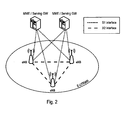
- the eNodeBs are also connected by means of the S1 interface to the EPC (Evolved Packet Core), more specifically to the MME (Mobility Management Entity) by means of the S1-MME and to the Serving Gateway (SGW) by means of the S1-U.
- EPC Evolved Packet Core
- MME Mobility Management Entity
- SGW Serving Gateway
- the S1 interface supports a many-to-many relation between MMEs/Serving Gateways and eNodeBs.
- the SGW routes and forwards user data packets, while also acting as the mobility anchor for the user plane during inter-eNodeB handovers and as the anchor for mobility between LTE and other 3GPP technologies (terminating S4 interface and relaying the traffic between 2G/3G systems and PDN GW).
- the SGW terminates the downlink data path and triggers paging when downlink data arrives for the user equipment. It manages and stores user equipment contexts, e.g. parameters of the IP bearer service, network internal routing information. It also performs replication of the user traffic in case of lawful interception.
- user equipment contexts e.g. parameters of the IP bearer service, network internal routing information. It also performs replication of the user traffic in case of lawful interception.
- the MME is the key control-node for the LTE access-network. It is responsible for idle mode user equipment tracking and paging procedure including retransmissions. It is involved in the bearer activation/deactivation process and is also responsible for choosing the SGW for a user equipment at the initial attach and at time of intra-LTE handover involving Core Network (CN) node relocation. It is responsible for authenticating the user (by interacting with the HSS).
- NAS Non-Access Stratum
- the Non-Access Stratum (NAS) signaling terminates at the MME and it is also responsible for generation and allocation of temporary identities to user equipments. It checks the authorization of the user equipment to camp on the service provider's Public Land Mobile Network (PLMN) and enforces user equipment roaming restrictions.
- PLMN Public Land Mobile Network
- the MME is the termination point in the network for ciphering/integrity protection for NAS signaling and handles the security key management. Lawful interception of signaling is also supported by the MME.
- the MME also provides the control plane function for mobility between LTE and 2G/3G access networks with the S3 interface terminating at the MME from the SGSN.
- the MME also terminates the S6a interface towards the home HSS for roaming user equipments.
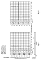
- the downlink component carrier of a 3GPP LTE is subdivided in the time-frequency domain in so-called subframes.
- each subframe is divided into two downlink slots as shown in Fig. 3 , wherein the first downlink slot comprises the control channel region (PDCCH region) within the first OFDM symbols.
- Each subframe consists of a give number of OFDM symbols in the time domain (12 or 14 OFDM symbols in 3GPP LTE (Release 8)), wherein each OFDM symbol spans over the entire bandwidth of the component carrier.
- the OFDM symbols thus each consists of a number of modulation symbols transmitted on respective N RB DL ⁇ N sc RB subcarriers as also shown in Fig. 4 .
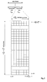
- a physical resource block is defined as N symb DL consecutive OFDM symbols in the time domain (e.g. 7 OFDM symbols) and N sc RB consecutive subcarriers in the frequency domain as exemplified in Fig. 4 (e.g. 12 subcarriers for a component carrier) .
- a physical resource block thus consists of N symb DL ⁇ N sc RB resource elements, corresponding to one slot in the time domain and 180 kHz in the frequency domain (for further details on the downlink resource grid, see for example 3GPP TS 36.211, "Evolved Universal Terrestrial Radio Access (E-UTRA); Physical Channels and Modulation (Release 8)", section 6.2, available at http://www.3gpp.org and incorporated herein by reference).
- One subframe consists of two slots, so that there are 14 OFDM symbols in a subframe when a so-called "normal” CP is used, and 12 OFDM symbols in a subframe when a so-called “extended” CP is used.
- the time-frequency resources equivalent to the same N sc RB consecutive subcarriers spanning a full subframe is called a "resource block pair", or equivalent "RB pair” or "PRB pair”.
- component carrier refers to a combination of several resource blocks in the frequency domain.
- cell refers to a combination of downlink and optionally uplink resources.
- the linking between the carrier frequency of the downlink resources and the carrier frequency of the uplink resources is indicated in the system information transmitted on the downlink resources.
- the frequency spectrum for IMT-Advanced was decided at the World Radiocommunication Conference 2007 (WRC-07). Although the overall frequency spectrum for IMT-Advanced was decided, the actual available frequency bandwidth is different according to each region or country. Following the decision on the available frequency spectrum outline, however, standardization of a radio interface started in the 3rd Generation Partnership Project (3GPP). At the 3GPP TSG RAN #39 meeting, the Study Item description on "Further Advancements for E-UTRA (LTE-Advanced)" was approved. The study item covers technology components to be considered for the evolution of E-UTRA, e.g. to fulfill the requirements on IMT-Advanced. Two major technology components are described in the following.
- the bandwidth that the LTE-Advanced system is able to support is 100 MHz, while an LTE system can only support 20 MHz.
- the lack of radio spectrum has become a bottleneck of the development of wireless networks, and as a result it is difficult to find a spectrum band which is wide enough for the LTE-Advanced system. Consequently, it is urgent to find a way to gain a wider radio spectrum band, wherein a possible answer is the carrier aggregation functionality.
- carrier aggregation two or more component carriers (component carriers) are aggregated in order to support wider transmission bandwidths up to 100MHz.
- component carriers component carriers
- Several cells in the LTE system are aggregated into one wider channel in the LTE-Advanced system which is wide enough for 100 MHz even though these cells in LTE are in different frequency bands.
- All component carriers can be configured to be LTE Rel. 8/9 compatible, at least when the aggregated numbers of component carriers in the uplink and the downlink are the same. Not all component carriers aggregated by a user equipment may necessarily be Rel. 8/9 compatible. Existing mechanism (e.g. barring) may be used to avoid Rel-8/9 user equipments to camp on a component carrier.
- a user equipment may simultaneously receive or transmit one or multiple component carriers (corresponding to multiple serving cells) depending on its capabilities.
- a LTE-A Rel. 10 user equipment with reception and/or transmission capabilities for carrier aggregation can simultaneously receive and/or transmit on multiple serving cells, whereas an LTE Rel. 8/9 user equipment can receive and transmit on a single serving cell only, provided that the structure of the component carrier follows the Rel. 8/9 specifications.
- Carrier aggregation is supported for both contiguous and non-contiguous component carriers with each component carrier limited to a maximum of 110 Resource Blocks in the frequency domain using the 3GPP LTE (Release 8/9) numerology.
- the MAC layer provides a data transfer service for the RRC layer through logical channels.
- Logical channels are either Control Logical Channels which carry control data such as RRC signalling, or Traffic Logical Channels which carry user plane data.
- Broadcast Control Channel (BCCH), Paging Control channel (PCCH), Common Control Channel (CCCH), Multicast Control Channel (MCCH) and Dedicated Control Channel (DCCH) are Control Logical Channels.
- Dedicated Traffic channel (DTCH) and Multicast Traffic Channel (MTCH) are Traffic Logical Channels.
- Transport Channels Data from the MAC layer is exchanged with the physical layer through Transport Channels. Data is multiplexed into transport channels depending on how it is transmitted over the air. Transport channels are classified as downlink or uplink as follows. Broadcast Channel (BCH), Downlink Shared Channel (DL-SCH), Paging Channel (PCH) and Multicast Channel (MCH) are downlink transport channels, whereas the Uplink Shared Channel (UL-SCH) and the Random Access Channel (RACH) are uplink transport channels.
- BCH Broadcast Channel
- DL-SCH Downlink Shared Channel
- PCH Paging Channel
- MCH Multicast Channel
- UL-SCH Uplink Shared Channel
- RACH Random Access Channel
- a multiplexing is then performed between logical channels and transport channels in the downlink and uplink respectively.
- L1/L2 control signaling is transmitted on the downlink along with the data.
- L1/L2 control signaling is multiplexed with the downlink data in a subframe, assuming that the user allocation can change from subframe to subframe.
- user allocation might also be performed on a TTI (Transmission Time Interval) basis, where the TTI length can be a multiple of the sub-frames.
- TTI length may be fixed in a service area for all users, may be different for different users, or may even by dynamic for each user.
- the L1/2 control signaling needs only be transmitted once per TTI. Without loss of generality, the following assumes that a TTI is equivalent to one subframe.
- the L1/L2 control signaling is transmitted on the Physical Downlink Control Channel (PDCCH).
- a PDCCH carries a message as a Downlink Control Information (DCI), which includes resource assignments and other control information for a mobile terminal or groups of UEs.
- DCI Downlink Control Information
- several PDCCHs can be transmitted in one subframe.
- uplink scheduling grants or uplink resource assignments are also transmitted on the PDCCH.
- the information sent on the L1/L2 control signaling may be separated into the following two categories, Shared Control Information (SCI) carrying Cat 1 information and Downlink Control Information (DCI) carrying Cat 2/3 information.
- SCI Shared Control Information
- DCI Downlink Control Information
- the different DCI formats that are currently defined for LTE are as follows and described in detail in 3GPP TS 36.212, "Multiplexing and channel coding", section 5.3.3.1 (available at http://www.3gpp.org and incorporated herein by reference).
- PDCCH Physical Downlink Control Channel
- PDSCH Physical Downlink Shared Channel
- the physical downlink control channel (PDCCH) carries e.g. scheduling grants for allocating resources for downlink or uplink data transmission.
- Each PDCCH is transmitted using one or more so called Control Channel Elements (CCEs).
- CCE corresponds to a set of Resource Elements (REs).
- REs Resource Elements
- 3GPP LTE at the moment one CCE consists of 9 Resource Element Groups (REGs), where one REG consists of four consecutive REs (consecutive in the frequency domain) excluding potential REs of reference signals.
- the resource elements occupied by reference symbols are not included within the REGs, which means that the total number of REGs in a given OFDM symbol depends on whether or not reference signals are present.
- the PDCCH for the user equipments is transmitted on the first N symb PDCCH OFDM symbols (usually either 1, 2 or 3 OFDM symbols as indicated by the PCFICH, in exceptional cases either 2, 3, or 4 OFDM symbols as indicated by the PCFICH) within a subframe, extending over the entire system bandwidth; the system bandwidth is typically equivalent to the span of a cell or component carrier.
- the region occupied by the first N symb PDCCH OFDM symbols in the time domain and the N RB DL ⁇ N sc RB subcarriers in the frequency domain is also referred to as PDCCH region or control channel region.
- the remaining N symb PDCCH 2 ⁇ N symb DL - N symb PDCCH OFDM symbols in the time domain on the N RB DL ⁇ N sc RB subcarriers in the frequency domain is referred to as the PDSCH region or shared channel region (see below).
- the PDCCH For a downlink grant on the physical downlink shared channel (PDSCH), the PDCCH assigns a PDSCH resource for (user) data within the same subframe.
- the PDCCH control channel region within a subframe consists of a set of CCE where the total number of CCEs in the control region of subframe is distributed throughout time and frequency control resource. Multiple CCEs can be combined to effectively reduce the coding rate of the control channel. CCEs are combined in a predetermined manner using a tree structure to achieve different coding rate.
- a PDCCH can aggregate 1, 2, 4 or 8 CCEs.
- the number of CCEs available for control channel assignment is a function of several factors, including carrier bandwidth, number of transmit antennas, number of OFDM symbols used for control and the CCE size, etc.
- Multiple PDCCHs can be transmitted in a subframe.
- L1/L2 control signaling On a transport channel level, the information transmitted via the PDCCH is also referred to as L1/L2 control signaling.
- L1/L2 control signaling is transmitted in the downlink for each user equipment (UE).
- the control signaling is commonly multiplexed with the downlink (user) data in a subframe (assuming that the user allocation can change from subframe to subframe).
- the physical downlink shared channel (PDSCH) is mapped to the remaining OFDM symbols within one subframe that are not occupied by the PDCCH.
- the PDSCH resources are allocated to the user equipments in units of resource blocks for each subframe.
- cell-specific reference signals CRS (Common Reference Signal) are transmitted. These cell-specific reference signals are transmitted on one or several of antenna ports 0 to 3.
- the CRS are transmitted from two antenna ports: R0 is from antenna port 0 and R1 is from antenna port 1.
- Fig. 6 shows another example where the PDCCH and the PDSCH is mapped to a MBSFN subframe.
- the example of Fig. 6 is quite similar to Fig, 5 , except for the MBSFN subframe not comprising common reference signals in OFDM symbols outside of the control channel region..
- Fig. 7 illustrates a resource block pair and the CRS for antenna ports 0 to 3, as defined in the technical standard TS 36.211v10.4 Chapter 6.10, incorporated herewith by reference; in particular Fig. 6 .10.1.2-1 where a normal cyclic prefix is assumed.
- the subframe also contains UE-specific reference signals, such as DMRS (DeModulation Reference Signal) that are used by the user equipments for demodulating the PDSCH.
- DMRS DeModulation Reference Signal
- the DMRS are only transmitted within the resource blocks where the PDSCH for a certain user equipment is allocated. In the example of Fig. 8A , only DMRS ports 7-10 are shown since these are assumed to be sufficient for ePDCCH transmissions. It should be noted that at the moment it is not supported to use DMRS for the PDSCH when also using SFBC.
- CSI-RS Channel-State-Information
- the CSI reference signal is transmitted in each physical antenna port or virtualized antenna port and is used for measurement purposes only.
- a cell can be configured with one, two, four or eight CSI-RS ports.
- the exact CSI-RS structure including the exact set of resource elements used for CSI-RS in a resource block, depends on the number of CSI-RS configured within the cell and may also be different for different cells. More specifically, within a resource-block pair there are 40 possible positions for the reference symbols of CSI-RS and, in a given cell, a subset of corresponding resource elements is used for CSI-RS transmission.
- the CSI-RS are transmitted (if configured) on one or more of antenna ports 15-22.
- Fig. 8A and 8B illustrate the reference signals DMRS and CSI-RS for a resource block pair, according to one example.
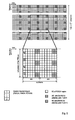
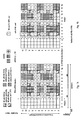
- Fig. 9 and 10 illustrate an exemplary mapping of resource elements to resource element groups within a physical resource block pair.
- one resource element group comprises four adjacent resource elements within each OFDM symbol.
- the resource elements that are used for the common reference signals are not used for defining a resource element group; in other words, when assigning the resource elements to resource element groups, the CRS REs are accounted for. Therefore, depending on the position of the CRS in the first OFDM symbol (which is cell specific), the mapping of REs to REGs is different.
- the mapping of REs to REGs is different.
- the differences are apparent; e.g. resource element of subcarrier 1 and OFDM symbol 0, may be either assigned to REG 1 ( Fig. 9 ) or may be used instead as a CRS ( Fig. 10 ).
- SFBCs Space-Frequency Block Codes
- SFBC is a transmit diversity technique used in LTE.
- transmit diversity is only defined for 2 and 4 transmit antennas and one data stream, referred to in LTE as one codeword since one transport block CRC is used per data stream.
- the SFBC diversity scheme may be used in LTE for the PBCH and PDCCH, and also for the PDSCH if it is configured in transmit diversity mode for a UE.
- SFBC is a frequency domain version of the well-known Space-Time Block Codes (STBCs), also known as Alamouti code. This family of codes is designed so that the transmitted diversity streams are orthogonal and achieve the optimal SNR with a linear receiver. Such orthogonal codes only exist for the case of two transmit antennas. Multiple subcarriers of OFDM lend themselves well to the application of SFBC.
- STBCs Space-Time Block Codes
- SFBC achieves robustness through frequency diversity by using different subcarriers for the repeated data on each antenna.
- an information symbol is transmitted on two different resource elements by using two distinct antennas (spatial component).
- the channel coefficient (amplitude/phase) for both versions is the same, the receiver can calculate the original symbol exploiting a diversity gain.
- the two versions of the information symbol are transmitted on adjacent subcarriers to be spaced closely in frequency; in said case, the channel coefficient for both versions can be assumed to be basically the same which improves the accurate regeneration of the information symbol using a simple receiver implementation, as shown by S.M. Alamouti "A Simple Transmitter Diversity Technique for Wireless Communication", IEEE Journal on Selected Areas in Communications, Vol. 16, pp. 1451-1458, October 1998 .
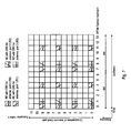
- Fig. 11 and 12 are similar to Fig. 9 and 10 respectively, as far as both illustrate the RE-to-REG mapping for the PDCCH considering the different positioning of the CRS. Furthermore, Fig. 11 and 12 also illustrate how SFBC may be applied to the PDCCH and to the PDSCH.
- LTE works such that the SFBC pairs are located as adjacent as possible in the frequency domain within one OFDM symbol; as depicted in Fig. 11, 12 in OFDM symbol 0 the possible SFBC pairs are each shown in a dashed-line box.
- SFBC pairs can therefore be mapped to resource elements (k',I') and (k'+n,l') in the same OFDM symbol, where k' is the subcarrier index, l' is the OFDM symbol number and n ⁇ 1,2 ⁇ .
- SFBC pairs can be mapped to resource elements (k',I') and (k'+n,l') in the same OFDM symbol, where k' is the subcarrier index, l' is the OFDM symbol number and n ⁇ 1, 2 ⁇ .
- LTE also allows a transmit diversity approach known as a combination of frequency switched transmit diversity (FSTD) with SFBC.
- FSTD schemes transmit symbols from each antenna on a different set of subcarriers. More information on FSTD is given in Chapter 11.2.2.1 of LTE - The UMTS Long Term Evolution - From Theory to Practice, Edited by Stefanie Sesia, Issam Toufik, Matthew Baker, Chapter 9.3, incorporated herein by reference.
- Enhanced PDCCH ePDCCH
- ePDCCH Enhanced PDCCH
- the mapping of Enhanced-PDCCH is preferred to be allocated in the PDSCH region, as depicted in Fig. 13 .
- the search space of ePDCCH would be limited within a set of PRBs pairs.
- the set of PRBs pairs can be first configured by higher layer signalling, or at least is assumed to be known by the receiver prior to trying to detect any ePDCCH.
- the ePDCCH consists of an aggregation of one or more control channel elements; in the following they may be exemplary called Enhanced Control Channel Elements (eCCEs).
- eCCEs Enhanced Control Channel Elements
- an eCCE may be formed from resource element groups that are mapped to resource elements in the time/frequency grid; they may be exemplary called Enhanced Resource Element Groups (eREGs).
- Fig. 13 schematically discloses the subframe content regarding PDCCH, ePDCCH and PDSCH, and further illustrates that for the ePDCCH 8 different eREG are exemplary assumed.
- the RE-to-eREG mapping for the ePDCCH (i.e. generally within or at least including REs from the PDSCH region) should allow for a SBFC transmission to achieve diversity, and advantageously should furthermore allow the application of the same mapping regardless of whether a diversity transmission is utilized or not.
- One object of the invention is to propose such a mapping of resource elements to resource element groups that also applies to the ePDCCH.
- resource elements (REs) of a resource block pair are assigned to enhanced resource elements groups (eREGs), where the assigning is such that it is universal (i.e. applies to a resource block pair irrespective of the reference signals blocking a resource element), in order to not be specific for a particular UE or cell. Further, the mapping is such that it considers the possible positioning of the reference signals in the resource block pair, so as to minimize the impact caused by the reference signals when using SFBC.
- the mapping is performed sequentially for each OFDM symbol of the resource block pair, and assigns the REs in each OFDM symbol to sequential eREGs (i.e. eREGs with a predetermined order of indices); the eREGs are cyclically extended such that an eREG 0 follows an eREG m max , where m max is the total number of eREGs for the resource block pair. Furthermore, the REs in each OFDM symbol are assigned in groups of two REs to the eREGs, where these two REs are spaced apart by either 3 or 6 subcarriers in the frequency domain; this is done until all REs of the OFDM symbol are assigned and then for each OFDM symbol.
- the 3 or 6 subcarrier spacing used for the mapping is due to the fact that this spacing corresponds to the spacing used for possible reference signals in the resource block pair.
- the reference signals block REs that are assigned to the same eREG, thus avoiding that REs are lost for SFBC when only one of the REs forming an SFBC pair is being blocked by a reference signal.
- the present invention provides a method for for assigning resource elements to resource element groups in a communication system using OFDM, Orthogonal Frequency-Division Multiplexing.
- the resource elements of a resource block pair are assigned to a plurality of m resource element groups according to a mapping that applies to each of a first and second frequency domain half of the resource block pair as follows:
- the resource elements of the first OFDM symbol are assigned to the resource element groups, in a first predetermined order of the resource elements and a second predetermined order of the resource element groups.
- the resource elements of the second OFDM symbol and of each further of the remaining OFDM symbols in the resource block pair are assigned to the resource element groups, in the first predetermined order of the resource elements and in the second predetermined order of the resource element groups, such that the first resource element group to be assigned is the one subsequent-in-order to the resource element group last assigned for the previous OFDM symbol.
- the first and second predetermined order is either an ascending or descending order.
- the assigning of resource elements to resource element groups is cyclic with respect to the resource element groups, such that the resource element group being last according to the second predetermined order is followed by the resource element group being first according to the second predetermined order.
- the ascending/descending order of the resource element groups starts with one out of the resource element groups, preferably with the first/last resource element group in the ascending/descending order.
- a resource element spans one subcarrier in a frequency domain and one OFDM symbol in the time domain, wherein a resource block pair spans 12 subcarriers in the frequency domain and 12 or 14 OFDM symbols in the time domain.
- the total number of resource element groups per resource block pair is 3, 4, 6 or 8.
- the total number of resource element groups per resource block pair is a multiple of the number of resource element groups that form a control channel element.
- the mapping is a universal mapping for the resource block pairs used in a OFDM communication system, such that the mapping applies independent from reference signals being assigned to some of the resource elements in the resource block pair.
- each resource element of the resource block pair is assigned to one of the plurality of resource element groups.
- a mobile terminal determines whether a velocity of the mobile terminal exceeds a predetermined velocity threshold. If the velocity threshold is exceeded, disregarding the resource elements of OFDM symbols of index 0 to ⁇ Ir in a resource block pair, where Ir is either 4, 3, 2 or 1.
- the embodiment may further transmit, if the velocity threshold is exceeded, by the mobile terminal information to the base station about Ir.
- the step of disregarding the resource elements comprises the step of setting the log-likelihood ratio of the resource elements of the OFDM symbols of index 0 to ⁇ Ir to zero.
- a base station determines whether a velocity of the mobile terminal exceeds a predetermined velocity threshold. If the velocity threshold is exceeded, the resource elements of OFDM symbols of index 0 to ⁇ Ir in a resource block pair are transmitted with zero power, where Ir is either 4, 3, 2 or 1.
- the embodiment may further comprise the step of informing the mobile terminal about Ir, if the velocity threshold is exceeded.
- the mapping refers to an enhanced Physical Downlink Control Channel
- the plurality of resource element groups is a plurality of enhanced resource element groups.
- space-frequency block coding is used for transmitting resource element groups in a resource block pair.
- One out of a plurality of SFBC pairs is defined to use two resource elements of the same resource element group within each OFDM symbol, the two resource elements of the SFBC pair being spaced apart either by 3 or 6 resource elements in the frequency domain.
- k' is the subcarrier index within the resource block pair with k' ⁇ 0, 1, 2 ...10 11 ⁇
- l' is the OFDM symbol index within the resource block pair with l' ⁇ 0, 1, 2...11, 12 ⁇ or l' ⁇ 0, 1, 2...13, 14 ⁇
- d sc is either 3 or 6
- t is N sc RB or N sc RB / 2
- N sc RB is the number of subcarriers per resource block and is preferably 12.
- the two resource elements of the SFBC pair are spaced apart either by disc in the frequency domain.
- the at least two resource element groups form a control channel element, and preferably wherein the indexes of the at least two resource element groups forming the control channel element are different.
- the invention further provides a terminal for receiving control channel information based on resource element groups, where resource elements are assigned to resource element groups in a communication system using OFDM, Orthogonal Frequency-Division Multiplexing.
- the resource elements of a resource block pair are assigned to a plurality of m resource element groups according to a mapping that applies to each of a first and second frequency domain half of the resource block pair, wherein the mobile terminal comprises a processor to apply the mapping where:
- a processor applies the mapping for receiving at least one resource element group as follows: the association for the at least one resource element group is determined by applying the mapping resulting explained in any of the above embodiments.
- a receiver and processor are adapted to decode at least one ePDCCH based on the eREG-to-RE mapping of the corresponding eREGs that form the ePDCCH.
- frequency domain half refers to a part of the resource block, the "frequency domain half” spanning either the first or last 6 subcarriers for all OFDM symbols of a resource block pair, when a physical resource block spans 12 subcarriers in the frequency domain, as is assumed in this description without loss of generality.
- spaced apart refers to the distance between two resource elements in the frequency domain, and shall be used as follows.
- a resource element with the subcarrier index k is spaced apart by 3 resource elements with regard to the resource element with the subcarrier index k+3.
- the indices of l', k' start with index 0, while the index of eREG start with 1.
- the particular start index is not important for the functioning of the invention.
- a different start index may be chosen for each of l', k' and m'.
- formulas or other procedures can be easily modified by those skilled in the art to take a different indexing into account.
- the PDCCH region spans the first 3 OFDM symbols, albeit it may span the first 1 or the first 2 OFDM symbols or might be not present at all (equivalent to spanning 0 OFDM symbols); correspondingly, the invention should not be restricted to a PDCCH region of 3 OFDM symbols but applies accordingly to different PDCCH regions of 1 and 2 OFDM symbols, or even a non-present PDCCH region (equivalent to a size of 0 OFDM symbols).
- Normal cyclic prefix is assumed if not mentioned differently, where the subframe has 14 OFDM symbols and not 12 OFDM symbols as with the extended cyclic prefix; the invention should not be restricted to a subframe of 14 OFDM symbols, since the principles of the invention apply accordingly to a subframe of 12 OFDM symbols.
- the embodiments refer to a mapping rule that assigns sequential resource elements to sequential enhanced resource element groups; the assigning follows a particular order. In most of the embodiments an ascending order is assumed. However, this is not necessary; instead, a descending order may be used, or any other predetermined order.
- one eCCE consists of two eREGs. At least two eREGs are required in order to enable a distributed transmission as outlined later in this document.
- a preferred solution that offers a good tradeoff between granularity and management complexity is offered by splitting the PRB pair into 8 eREGs, and to combine two eREGs into one eCCE which is the smallest unit for an L1/L2 control signaling transmission.
- a small L1/L2 control signaling size in a 10 MHz LTE cell can be around 30 bits
- a large L1/L2 control signaling size in a 10 MHz LTE cell can be around 60 bits
- a typical size is around 45 bits.
- each used RE can carry 2 bits. Consequently, if an eCCE includes around 30 REs, this is equivalent to 60 codebits, which results for the typical L1/L2 control signaling size in a code rate of 3/4, which can be seen as a coderate that is suitable for good channel conditions.
- one eREG is mapped to REs of one PRB pair. Then, combining at least two eREGs allows a distributed transmission, as outlined later in this document. In case that for example only one eREG forms an eCCE, then it may be preferred to allow the mapping of a single eREG to multiple PRB pairs. It may further be beneficial to allow a larger distribution for any number of eREGs in an eCCE; for example, if two eREGs form an eCCE and one eREG is mapped to only a single PRB pair, the distributed transmission on in total two different PRB pairs obtains a diversity order of two.
- each eREG is mapped to two PRB pairs, then each eREG obtains a diversity order of two, so that the combination of two eREGs can obtain a diversity order of up to four. Therefore, it should not be construed that the present invention is limited to mapping one eREG only to REs of one PRB pair.
- Fig. 14 shows a resource element to enhanced resource element group mapping that is applied to the PDSCH region (assuming it starts at OFDM symbol #3), where the ePDCCH will be located.
- the RE-to-eREG mapping of Fig. 14 is according to the rules applied for the RE-to-REG used for the PDCCH.
- the RE-to-eREG mapping rule is such that resource elements that are used for reference signals (such as CRS, CSI-RS, DMRS) are not used for the mapping.
- the grouping of the resource elements to an eREG is performed sequentially in groups of two resource elements to an eREG, in ascending order of the subcarriers within each OFDM symbol and then in an ascending order of OFDM symbols.
- the eREGs indices are in an ascending order and are cyclically extended such that after (in this case, assuming there are 8 eREGs) assigning eREG8 to a resource element pair, eREG1 is assigned next; this can be seen for example in OFDM symbol 4, at subcarriers 4, 5 and 7, 8. In this way all resource elements of a resource block pair, that are not used by reference signals, are assigned to an enhanced resource element group.
- Fig. 15 discloses which resource elements can be used for SFBC, and which resource elements cannot be used for SFBC.
- an SFCB pair in an OFDM symbol shall be composed of either adjacent resource elements of the same eREG (i.e. spaced apart by one resource element) or of resource elements of the same eREG that are spaced apart by two REs (i.e. only one resource element in between).
- some SFBC pairs are exemplary illustrated for OFDM symbol 4 (in this case, SFBC pairs are composed of adjacent resource elements).
- the mapping algorithm is cell specific; this also applies to the RE-to-REG rule applied in the PDCCH region.
- the location of the CRS can be different in frequency, as shown in Fig. 11 and 12 , where the CRS are shifted by one subcarrier in the frequency domain.
- This cell-specific mapping may however lead to interference problems as will be explained with reference to Fig. 16 and 17 .
- the CRS location in the PRB pair of Fig. 16 is different from the CRS location of Fig. 17 ; CRS are shifted by two subcarriers in the frequency domain.
- the interference problems caused by the cell-specific mapping will be discussed mainly with reference to the PDCCH region of Fig. 16 and 17 .
- the interference problems explained in the following occur as well in the RE-to-eREG mapping in the PDSCH region.
- the resource element (11,0) is assigned in cell 1 to (e)REG2, and in cell 2 this resource element (11,0) is not assigned to any (e)REG but is used for the common reference signal.
- this resource element (11,0) is not assigned to any (e)REG but is used for the common reference signal.
- the same resource element in the same physical resource block pair is used differently. Consequently, the resource element in cell 2 used for CRS can cause strong interference with the same resource element from cell 1, and vice versa. This may even lead to data loss of resource element (11,0), since reference signals are generally transmitted with high transmission power.
- the SFBC pair in OFDM symbol 0 at subcarriers 10, 11 might become void due to the interference caused by the CRS resource element (11,0) of cell 2.
- the resource element (11,0) of cell 1 experiencing interference from the same resource element of cell 2, could be muted (or voided) so as to not generate interference to the CRS in cell 2, in order to improve a UE's channel estimation quality of the cell 2 CRS; such a muting (or voiding) would be indicated to the other cell(s) and/or UE(s) generally by RRC signaling, and the resource element would not be used for transmission in cell 1.
- SFBC this would mean that the whole SFBC pair could not be used, and RE(10,0) would be void as a consequence too. Therefore a whole SFBC pair is lost even though just a single RE needs to be muted, resulting in a reduced spectral efficiency operation in cell 1.
- the RE-to-eREG mapping explained with reference to Fig. 14 is not only cell-specific as just explained with reference to Fig. 16 and 17 , but is also UE-specific, for the reason that the DMRS and CSI-RS configuration/presence is UE-specific and corresponding REs are not used for the RE-to-eREG mapping of Fig. 14 .
- the RE-to-eREG mapping in the PDSCH region also may differ from UE to UE. This issue will be explained in more detail with regard to Fig. 18 and 19 .
- Fig. 18 and 19 disclose different RE-to-eREG mappings for UE1 and UE2, based on the RE-to-eREG mapping rule introduced for Fig. 14 .
- Fig. 18 has the same RE-to-eREG mapping as Fig. 14 , since the same number and location of reference signals is assumed.
- Fig. 19 differs in the RE-to-eREG mapping since a different CSI-RS is assumed for UE2.
- the resource elements (4,9),(4,10), (5,9), (5,10) and (10,9), (10,10), (11,9), (11,10) are not used for CSI-RS but may be assigned to eREGs.
- subcarrier 1 is the same for both UEs; however, the remaining grouping of resource elements is different, illustrated within dashed-lines box in Fig. 19 .
- Optimal multiplexing is therefore not possible in case eREG #3 should be used to transmit an ePDCCH to UE1 at the same time that eREG #7 should be used to transmit an ePDCCH to UE2.
- eREG #7 should be used to transmit an ePDCCH to UE2.
- eREG combinations that still allow optimal multiplexing; however, discovering those will increase the complexity for the network and significantly reduces the flexibility (since not every eREGs can be assigned to any UE), as well as reduce the spectral efficiency (since it might likely occur that not all eREGs can be utilised by the network in the same subframe).
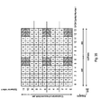
- Fig. 20 introduces a different RE-to-eREG mapping that is cell and UE independent, i.e. a universal/uniform mapping to be applied to the whole of the PRB pair without considering the cell-specific and UE-specific reference signals, or other signals or channels.
- a universal/uniform mapping to be applied to the whole of the PRB pair without considering the cell-specific and UE-specific reference signals, or other signals or channels.
- the resource elements are assigned to ascending eREGs in pairs of two adjacent REs in ascending order of the subcarriers within each OFDM symbol, and then in ascending order of OFDM symbols.
- the assigning of two adjacent REs to the same eREG is mainly done for supporting SFBC. The assigning is done without taking into account the reference signals in the physical resource block pair.
- the eREGs are cyclically extended such that eREG numbes are assigned as follows ⁇ 1,2,3,4,5,6,7,8,1,2,3,4,5,6,7,8,1,2,3,... ⁇ until all resource elements of a physical resource block pair are assigned to one out of the m max eREG.
- Fig. 20 where the resource elements are assigned to 8 eREGs 1-8.
- the reference signals are disregarded, i.e. not considered.
- eREGs are assigned to pairs of adjacent REs (adjacent in the frequency domain) in an ascending order of eREGs, in an ascending order of subcarriers within each OFDM symbol within a PRB pair, and in an ascending order to OFDM symbols in the PRB pair.
- Such a universal mapping as depicted in Fig. 20 is the same for different cells and for different UEs; correspondingly, the disadvantages stemming from cell-specific and UE-specific RE-to-eREG mappings are avoided.
- Each UE has the same understanding of which REs belong to which eREG, although some UE may be allowed to use some other REs than other UEs (due to differing UE-specific reference signals).
- Fig. 21 assumes the same RE-to-eREG mapping as for Fig. 20 , but further illustrates the CRS, DMRS (CSI-RS is disregarded for illustration purposes) and the use of SFBC. Put differently, the RE-to-eREG mapping of Fig. 20 is masked by the reference signals, such as those of Fig. 7 and 8 .
- the resource elements used for reference signals are blocked and cannot be used for transmissions or SFBC transmissions;
- Fig. 21 furthermore indicates those resource elements as void (V) that cannot be used for SFBC transmissions due to the masked RE used for reference signals signals and its effect on the SFBC pair.
- V void
- the resource elements (2,0), (3,0) cannot be used for SFBC transmissions, since eREG1 is assigned to (2,0) and eREG2 is assigned to (3,0), and the corresponding REs to form an SFBC pair are blocked by the CRS at (0,0) and (3,0).
- resource elements (7,0),(8,0) are void, etc.
- each eREG comprises resource elements in the whole physical resource block pair according to the following table: eREG1 eREG2 eREG3 eREG4 eREG5 eREG6 eREG7 eREG8 average Size in RE 12 12 16 8 14 14 10 18 13
- the eREG size varies between 8 for eREG 4 and 18 for eREG8, in the particular example of Fig. 21 ; this is a significant variation that is disadvantageous.
- the eREG index is determined by two numbers: the eREG index p within a PRB pair e.g. as shown in Fig. 20 , and the PRB pair index q where the eREG is transmitted. Therefore, an eREG index (p,q) occupies the same REs relative to the PRB pair as eREG index (a,q+1), just in another PRB pair.
- eREGs form an eCCE
- eREGs In a localised eCCE transmission, the eREGs should reside in the same PRB pair, so that e.g. eREG (p, q) and eREG (p', q) form an eCCE, where p is not equal to p'.
- the eREGs In distributed transmission, the eREGs should reside in different PRB pairs, such that e.g. eREG (p, q) and eREG (p', q') form an eCCE, where q is not equal to q'.
- a universal mapping may consider reference signals, but only in case the reference signals are always present, i.e. are not cell or UE specific.Thus, a universal mapping applies in the same manner to all resource block pairs independent from the particular cell or UE-specific reference signals that are transmitted. As a result, when such a common mapping is assumed, all resource elements of a PRB pair are available for eREGs, and not just those that are not used for reference signals, again, with the restriction explained in connection with Fig. 33-35 .
- a new carrier type could be characterised by the lack of the control channel region (PDCCH, i.e. the control region size is 0), or the lack or reduced density of CRS transmissions, or the introduction of additional reference (or other) signals, or the redefinition of currently defined signals that would be transmitted on additional or different REs.
- PDCCH control channel region
- additional reference (or other) signals or the redefinition of currently defined signals that would be transmitted on additional or different REs.
- Such REs would be handled just like currently defined signals, i.e. they would be applied as a kind of masking to the universal mapping when determining which RE is available for a transmission; however, the order or the association of REs to eREGs would not be affected.
- the improved RE-to-eREG mapping rule of this embodiment shall also have a good performance when used for SFBC as well without SFBC.
- the mapping rule shall be common to all PRB pairs as explained above (i.e. disregard the reference signals), this improved mapping rule shall still consider the positioning of the reference signals in the resource block pair in a different way. In particular, in order to reduce the amount of the resource elements that become void (i.e.
- the mapping rule shall be such that it considers the positioning of the reference signals to achieve an optimum performance. Since the association of an RE to an eREG index is not depending on whether SFBC is used for that eREG according to the present invention, it is possible to use REs in the non-SFBC case that would be blocked or voided in the SFBC case.
- the present invention also allows multiplexing of eREGs that use SFBC and that do not use SFBC in the same PRB pair, greatly increasing the multiplexing capability and flexibility for the network, and therefore simplifying to reach the target of an efficient usage of the available resources.
- the assigning of a resource element pair to the same eREG is such that said two resource elements of the resource element pair within the OFDM symbol are not adjacent (as done so far, e.g. Fig. 20 ) but are spaced apart according to the positioning of the reference signals.
- the separate CRS are spaced apart by six subcarriers; e.g. the CRS for antenna port 0 are at subcarriers 0, 6 in OFDM symbols 0, 7 and at subcarriers 3, 9 in OFDM symbols 4, 11; e.g. the CRS for antenna port 3 is positioned at subcarriers 3, 6 in OFDM symbol 1, and at subcarriers 0, 6 in OFDM symbol 8. While the particular CRS are spaced apart by 6 subcarriers (as shown above), when considering more than one CRS, the CRS are spaced apart by three subcarriers in the frequency domain; e.g. for OFDM symbols 0, 1, 4, 7, 8 and 11, at subcarriers 0, 3, 6, 9.
- DMRS and CSI-RS of Fig. 8A and 8B where within one OFDM symbol the same reference signal is spaced apart by 5 or 6 subcarriers (i.e. 5 or 6 resource elements in the frequency domain).
- DMRS for antenna ports 7 and 8 are located at subcarriers 0, 5 in OFDM symbols 5, 6, 12, 13; thus, with a difference of 5 subcarriers.
- the CSI-RS are repeated every 6 subcarriers, as apparent from Fig. 8B .
- two resource elements to be assigned to the same eREG in an OFDM symbol are spaced apart by 6 subcarriers, i.e. 6 resource elements in the frequency direction.
- the RE-to-eREG mapping sequentially assigns REs to eREGs in a predetermined order (in the following in an ascending order) of subcarriers, OFDM symbols and enhanced resource element groups.
- Fig. 22 The thus resulting mapping rule how eREGs are assigned to the resource elements of a resource block pair is illustrated in Fig. 22 .
- the eREGs are sequentially and cyclically assigned to the resource elements ascending by subcarrier for each OFDM symbol and ascending by OFDM symbol until all resource elements of the lower part of the resource block pair are assigned to an eREG; the same applies to the upper half of the resource block pair.
- Fig. 23 When actually applying this mapping rule, the RE-to-eREG mapping of Fig. 23 is achieved; a total number of 8 eREGs is assumed therein.
- Fig. 24-27 show the RE-to-eREG mapping according to this mapping rule of Fig. 22 respectively for 6, 5, 4, 3 eREGs.
- the eREGs are assigned as follows:
- d sc refers to the subcarrier difference and basically indicates how much the two resource elements are spaced apart in each OFDM symbol, and is a design parameter; it may be preferably either 3 or 6.
- "t" is N sc RB or N sc RB (/2), wherein N sc RB is the number of subcarriers per resource block and is preferably 12. It may be noted that even if d sc is set to 6, the result can look like e.g.
- Fig. 27 where the distance between two REs belonging to the same eREG is 3, or e.g. shown in Fig. 26 where the distance is sometimes 2 and sometimes 4; however the common characteristic is that at a distance of 6, two REs will always be assigned to the same eREG index.
- REs, (k',l') (k + d sc ,l') form an SFBC pair in case SFBC should be used, as will be explained in more detail later.
- the RE-to-eREG mapping rule for the exemplary embodiment of Fig. 22 may be as follows.
- the RE-to-eREG mapping rule applies similarly to lower and upper part of the resource block pair.
- the resource elements of the first OFDM symbol are assigned to the resource element groups, in a first predetermined order of the resource elements in the frequency domain (i.e. of subcarriers) and a second predetermined order of the resource element groups, wherein the first and second predetermined orders are an ascending order in this particular case.
- the resource elements of the second OFDM symbol and of each further of the remaining OFDM symbols in the resource block pair are assigned to the resource element groups, in the same first predetermined order of the resource elements and in the same second predetermined order of the resource element groups; however, with the further rule that the first resource element group to be assigned in this second or further OFDM symbol is the one subsequent-in-order to the resource element group last assigned for the previous OFDM symbol.
- the starting number of the eREGs is 1.
- the starting number of the assigning of eREGs may be any another number; for example the starting number may be 8, when assuming a total of 8 eREGs, and more in general m max .
- the association between RE and eREG within an OFDM symbol is done in such a way as to arrive in an assignment of number of REs per eREG as fairly as possible within the above constraints, taking the REs into account that are assigned in other OFDM symbols of the same subframe and PRB pair.
- Fig. 28 exemplifies the above-described RE-to-eREG mapping rule for descending orders of OFDM symbols and subcarriers within each OFDM symbol; the order for the eREG may be either ascending, descending or any other predetermined order.
- Fig. 29 exemplifies the above-described RE-to-eREG mapping rule for a descending order of subcarriers within each OFDM symbol but for an ascending order of OFDM symbols; again, the order for the eREGS may be either ascending, descending or any other predetermined order.
- Fig. 30 illustrates the same RE-to-eREG mapping of Fig. 23 ; furthermore, Fig. 30 also illustrates exemplary reference signals, such as the CRS and DMRS and illustrates how SFBC can be applied to the eREGs of the resource block pair.
- an SFBC pair is composed of two resource elements in the same OFDM symbol assigned to the same eREG, the resource elements of the SFBC pair being spaced by six subcarriers, i.e. k' and k'+6.
- Fig. 30 only two SFBC pairs are exemplary depicted; of course, SFBC is applied to all possible resource element pairs, if needed.
- An RE that is assigned to an eREG is only used for an eCCE transmission if all of the following criteria are met:
- the reference signals CRS do not cause additional resource elements to become void, since each CRS for antenna port 0 uses two resource elements that are spaced apart by 6, which is the same as the spacing used for the RE-to-eREG.
- the CRS block resource elements within an OFDM symbol that are assigned to the same eREG and forming one (or generaiiy more) SFBC pair, due to the mapping rule being adapted in that way.
- the eREG size varies between 12 and 18. Compared to the RE-to-eREG mapping of Fig. 20 , the eREG size is more balanced, which allows for a more evenly distributed signal quality in case different eREGs are tied to different antenna ports for channel estimation/ demodulation. The more balanced eREG size also allows for a more fair frequency diversity in case of mapping to distributed PRB pairs.
- the average eCCE size is 30 resource elements, in the above example of Fig. 30 (i.e. with SFBC, CRS and 24 DMRS).
- the average eREG size of the embodiment of the invention is higher by 2 resource elements; put differently, about 15 % higher(when calculating the the benefit as the ratio 2/13).
- Another advantage of this embodiment of the invention is that the utilization of SFBC can be applied per eREG index, so that even in the same PRB pair certain eREGs can utilize SFBC and other eREGs do not utilize SFBC; still all eREGs use the same mapping of REs to eREGs, which allows a very flexible utilization of all resources in a PRB pair even for intended receivers that have different transmission requirements (e.g. with and without transmit diversity, such as SFBC).
- m max is a multiple of the number of eREGs that are combined to form an eCCE.
- different eREGs belonging to the same eCCE are transmitted in different PRB pairs, which allows for obtaining frequency diversity (from the radio channel perspective) and/or noise/interference diversity (from the noise or interference perspective that might be generated by neighbouring transmitters or other noise/interference sources).
- the eREGs that are combined to form an eCCE have preferably different indices. If eREGs of the same PRB pair are combined, then this is straightforward because each eREG can only be used once per PRB pair. In the case of combining eREGs of at least two different PRB pairs, this should be done for uniformity of the indexing and combination, and also because in this way the resulting number of REs per eCCE can be equalized across eCCEs. As shown, the number of REs per eREG may differ from eREG to eREG, but it is generally independent of the PRB pair where the eREG (or eCCE) is/are mapped.
- eREG index numbering is identical in each PRB pair
- combining different eREG indices into an eCCE allows therefore more similar number of REs in the resulting eCCEs.
- the underlying principle is not tied to the eREG index as such, but rather to the RE positions within each PRB pair. So in case that the eREG indexing is different for different PRB pairs, it is still preferred that an eCCE is formed by combining REs with different indices k',l' relative to each PRB pair, which for convenience and abstraction reasons is equivalent in this description to the eREG index.
- the above shown formula can be used as well.
- Fig. 31 shows the mapping rule to be applied so as to assign eREGs in a cyclically extended order to the resource elements as indicated by the meander-like arrows.
- Fig. 32 shows the result, i.e. the RE-to-eREG mapping when using 8 eREGs and an ascending order of the eREGs.
- the UE shall always consider certain DMRS to be present in a resource block pair.
- the presence of those DMRS are no longer UE-specific but may be considered to be present for every UE alike, at least for matters of associating the REs to eREGs; every UE assumes that certain DMRS are present or transmitted on the corresponding resource elements, or at least that the corresponding REs cannot be used for any eREGs (i.e. they are reserved). This does however not apply to the CSI-RS; they are still UE-specific.
- antenna ports 7-10 are in this way assumed to be always present by aii UEs.
- the RE-to-eREG mapping of the previous embodiments can be adapted to take the result of this assumption into account, to thus further reduce impact of reference signals.
- the RE-to-eREG mapping can be adapted such that the resource elements occupied by the DMRS shall not be assigned to an eREG but are skipped during the assigning process.
- the mapping can still be considered to be universal/uniform, since it is still cell and UE-independent.
- the corresponding RE-to-eREG mapping rule is depicted in Fig. 33 , for the case that the a RE spacing d sc of 6 is assumed and 24 REs are used for DMRS.
- the mapping rule the DMRS at OFDM symbols 5, 6, 12 and 13 are ignored for the assigning, i.e. the corresponding REs reserved or occupied by the DMRS are not used for the RE-to-eREG assigning.
- an SFBC pair in OFDM symbols 5, 6, 12 and 13 is formed by REs that are spaced apart by five resource elements, while the spacing for the SFBC is six for the remaining OFDM symbols.
- Fig. 34 is based on the mapping rule introduced with reference to Fig. 31 and 32 , but also skips the resource elements reserved for the DMRS, similar to Fig. 33 .
- the resulting mapping rule and the result thereof are depicted in Fig. 34 . While in OFDM symbols 0-4, 7-11 an SFBC pair is formed by resource elements being spaced by 3 subcarriers, in OFDM symbols 5, 6, 12 and 13 the spacing varies, though SFBC pairs could be formed since there are respectively two REs per eREG.
- step 4 could be replaced by the following steps (where step 8 points to step 4a instead):
- FIG. 35 Another embodiment of the invention is illustrated in Fig. 35 . Similar to the embodiments of Fig. 33 and 34 , the resource elements reserved or occupied by DMRS are skipped for the RE-to-eREG assigning. However, the actual RE-to-eREG mapping rule differs additionally, from the previous ones. As can be seen from Fig. 35 , a basic spacing of 3 is used; i.e. resource elements that are spaced apart by 3 subcarriers are assigned to the same eREG.
- the assigning of eREG starts in the two parts of the upper half with that index which succeeds the last one used for the two parts of the lower half.
- assigning three different eREGs to the resource elements within one OFDM symbol see Fig. 31, 32 )
- a total of six different eREGs are assigned.
- eREGs1-3 are assigned in the sequential order.
- eREGs 4-6 are assigned respectively in the two parts.
- the subsequent eREGs 7-8 and the cyclically extended eREG 1 are mapped to the resource elements of the two parts of the lower OFDM half.
- the eREGs are assigned that are subsequent-in-order to the ones assigned in the previous OFDM symbol; e.g. in OFDM symbol 8 the six eREGs 3-8 are assigned, which results in that for the subsequent OFDM symbol 9 the six eREGS 1-6 are assigned to the resource elements.
- SFBC When SFBC is applied for transmissions based on the RE-to-eREG mapping of Fig. 35 , it can be seen that for OFDM symbols 1-4, 7-11 a SFBC spacing of 3 is used (i.e. spacing in subcarriers between the REs forming one SFBC pair), while in OFDM symbols 5, 6, 12 and 13 a SFBC spacing of 5 is used. As with Fig. 33 , no REs become void for SFBC in OFDM symbols 5, 6, 12 and 13 due to the reference signals.
- the fading in time causes an inaccurate estimation especially for the first OFDM symbols in a subframe, since the DMRS and CSI-RS are only available as of OFDM symbol 5 (see Fig. 8 ).
- the quality of the first OFDM symbols may be extrapolated from the reference signals transmitted at OFDM symbols 5, 6, 9, 10, 12 and 13.
- the estimation may differ significantly from the actual received signal quality, which is especially true when the mobile terminal moves at high velocities, such as 100 km/h.
- the mobile terminal may monitor its own velocity, and determine whether it exceeds a predetermined velocity threshold.
- the threshold is set such that it may be assumed that the estimation of channel quality for at least some of the first OFDM symbols (i.e. OFDM symbols 0-4) based on the one of OFDM symbols 5-13 is not accurate enough.
- the mobile terminal disregards the resource elements of OFDM symbols of index 0 to ⁇ Ir in a resource block pair, where Ir is either 4, 3, 2 or 1.
- Ir is either 4, 3, 2 or 1.
- the Log Likelihood (LLR) for those REs are nulled, meaning that the further processing of the resource elements assumed that the resource elements are unreliable and will thus be discarded by the UE. It is assumed that the redundancy in the resource block pair regarding the remaining REs suffices to correctly receive the data.
- Ir may be defined by the UE implementation and may thus differ from one UE to another. Therefore, it is advantageous that the mobile terminal transmits information about the particular Ir to the base station. Also , the base station may know the predetermined velocity threshold applied by the mobile terminal whether to use or not the first OFDM symbols. The predetermined velocity threshold is either preconfigured in the base station, or the base station is informed by the mobile terminal.
- the base station monitors the velocity of the mobile terminal to determine whether the UE velocity exceeds the corresponding threshold. If it exceeds the threshold, the base station may transmit the first Ir OFDM symbols with zero power (similar to RE-puncturing). Again the last OFDM symbol for which this is applied may be mainly up to the particular implementation, or may be informed to the base station by the mobile terminal.
- the base station may inform the mobile terminal of this fact.
- the PCFICH may be used in said respect.
- the mobile terminal would know when and which OFDM symbols he should not use.
- One advantage is that the power saved in the base station, due to transmitting the first OFDM symbols with zero power, could be used to boost e.g. resource elements in other PRB pairs in the corresponding "saved" OFDM symbols.
- the base station may e.g. estimate the UE velocity from the handover count.
- the UE In order for the eNB to be aware that the first symbols are unreliable for the UE, the UE includes a corresponding suggested starting OFDM symbol, e.g. in the CSI report applicable for ePDCCH.
- a knowledge at the eNB enables the eNB to not even transmit REs targeting the corresponding UEs with any power in the corresponding OFDM symbols; instead, the saved power can be used to increase the transmit power of other REs (such as those targeting a different UE that does not suggest a corresponding starting symbol) in the same OFDM symbol(s) to improve their quality at the receiver.
- Another embodiment of the invention relates to the implementation of the above described various embodiments using hardware and software.
- the invention provides a user equipment (mobile terminal) and a eNodeB (base station).
- the user equipment is adapted to perform the methods described herein.
- a computing device or processor may for example be general purpose processors, digital signal processors (DSP), application specific integrated circuits (ASIC), field programmable gate arrays (FPGA) or other programmable logic devices, etc.
- DSP digital signal processors
- ASIC application specific integrated circuits
- FPGA field programmable gate arrays
- the various embodiments of the invention may also be performed or embodied by a combination of these devices.
- the various embodiments of the invention may also be implemented by means of software modules, which are executed by a processor or directly in hardware. Also a combination of software modules and a hardware implementation may be possible.
- the software modules may be stored on any kind of computer readable storage media, for example RAM, EPROM, EEPROM, flash memory, registers, hard disks, CD-ROM, DVD, etc.
Priority Applications (6)
| Application Number | Priority Date | Filing Date | Title |
|---|---|---|---|
| EP12003945.8A EP2667535A1 (de) | 2012-05-21 | 2012-05-21 | Gemeinsames Mapping von Ressourcenelementen zu erweiterten Ressourcenelementgruppen |
| US14/402,209 US9560655B2 (en) | 2012-05-21 | 2013-05-15 | Common mapping of resource elements to enhanced resource element groups |
| EP13722470.5A EP2853056B1 (de) | 2012-05-21 | 2013-05-15 | Gemeinsames mapping von ressourcenelementen zu erweiterten ressourcenelementgruppen |
| JP2015513096A JP6100888B2 (ja) | 2012-05-21 | 2013-05-15 | エンハンストリソース要素グループへのリソース要素の共通マッピング |
| PCT/EP2013/060042 WO2013174695A1 (en) | 2012-05-21 | 2013-05-15 | Common mapping of resource elements to enhanced resource element groups |
| US15/384,121 US9717080B2 (en) | 2012-05-21 | 2016-12-19 | Common mapping of resource elements to enhanced resource element groups |
Applications Claiming Priority (1)
| Application Number | Priority Date | Filing Date | Title |
|---|---|---|---|
| EP12003945.8A EP2667535A1 (de) | 2012-05-21 | 2012-05-21 | Gemeinsames Mapping von Ressourcenelementen zu erweiterten Ressourcenelementgruppen |
Publications (1)
| Publication Number | Publication Date |
|---|---|
| EP2667535A1 true EP2667535A1 (de) | 2013-11-27 |
Family
ID=48430816
Family Applications (2)
| Application Number | Title | Priority Date | Filing Date |
|---|---|---|---|
| EP12003945.8A Withdrawn EP2667535A1 (de) | 2012-05-21 | 2012-05-21 | Gemeinsames Mapping von Ressourcenelementen zu erweiterten Ressourcenelementgruppen |
| EP13722470.5A Active EP2853056B1 (de) | 2012-05-21 | 2013-05-15 | Gemeinsames mapping von ressourcenelementen zu erweiterten ressourcenelementgruppen |
Family Applications After (1)
| Application Number | Title | Priority Date | Filing Date |
|---|---|---|---|
| EP13722470.5A Active EP2853056B1 (de) | 2012-05-21 | 2013-05-15 | Gemeinsames mapping von ressourcenelementen zu erweiterten ressourcenelementgruppen |
Country Status (4)
| Country | Link |
|---|---|
| US (2) | US9560655B2 (de) |
| EP (2) | EP2667535A1 (de) |
| JP (1) | JP6100888B2 (de) |
| WO (1) | WO2013174695A1 (de) |
Cited By (2)
| Publication number | Priority date | Publication date | Assignee | Title |
|---|---|---|---|---|
| CN109478987A (zh) * | 2016-05-23 | 2019-03-15 | 瑞典爱立信有限公司 | 用于处置通信的方法和用户设备 |
| EP3565155A4 (de) * | 2017-01-23 | 2020-01-01 | Huawei Technologies Co., Ltd. | Datenübertragungsverfahren und -vorrichtung |
Families Citing this family (33)
| Publication number | Priority date | Publication date | Assignee | Title |
|---|---|---|---|---|
| CN102420685B (zh) * | 2011-11-07 | 2014-08-06 | 电信科学技术研究院 | 一种传输控制信息的方法及装置 |
| WO2015069055A1 (ko) * | 2013-11-07 | 2015-05-14 | 엘지전자 주식회사 | 무선 통신 시스템에서 무선 통신 상태 측정 방법 및 이를 위한 장치 |
| CN104936184A (zh) * | 2014-03-21 | 2015-09-23 | 上海贝尔股份有限公司 | 基于协作多点在多个小区间进行资源分配的方法与设备 |
| US10187876B2 (en) * | 2015-01-12 | 2019-01-22 | Qualcomm Incorporated | Techniques for handling channel state information (CSI) in ultra low latency (ULL) LTE |
| US20160270038A1 (en) | 2015-03-11 | 2016-09-15 | Samsung Electronics Co., Ltd | Transmissions of downlink control channels for low cost ues |
| US10966194B2 (en) * | 2015-04-15 | 2021-03-30 | Qualcomm Incorporated | Coordinated wireless communications using multiple transmission time intervals |
| US11153868B2 (en) * | 2015-09-02 | 2021-10-19 | Ntt Docomo, Inc. | User equipment, wireless base station, and wireless communication method using multiple Transmission Time Interval (TTI) lengths |
| WO2017050376A1 (en) * | 2015-09-24 | 2017-03-30 | Huawei Technologies Co., Ltd. | Method and device in a wireless communication system |
| WO2017073083A1 (en) * | 2015-10-29 | 2017-05-04 | Sharp Kabushiki Kaisha | Systems and methods for multi-physical structure system |
| US11109372B2 (en) * | 2016-01-11 | 2021-08-31 | Qualcomm Incorporated | Narrow-band physical control channel design |
| CN107302796B (zh) | 2016-03-31 | 2023-04-18 | 华为技术有限公司 | 一种数据传输方法、网络侧设备及终端设备 |
| CN107306177B (zh) * | 2016-04-22 | 2023-11-10 | 华为技术有限公司 | 传输数据的方法、用户设备和网络侧设备 |
| EP3461195B1 (de) | 2016-06-03 | 2023-12-06 | Guangdong Oppo Mobile Telecommunications Corp., Ltd. | Verfahren und vorrichtung zur übertragung von daten |
| CN107547181B (zh) * | 2016-06-25 | 2023-10-24 | 华为技术有限公司 | 控制信息发送方法、接收方法、网络设备和终端设备 |
| US10433293B2 (en) * | 2016-06-29 | 2019-10-01 | Lg Electronics Inc. | Method and apparatus for receiving or transmitting downlink signal in a wireless communication system |
| KR102178412B1 (ko) | 2016-07-15 | 2020-11-16 | 주식회사 케이티 | 새로운 무선 액세스 망에서 단말을 위한 동기화 신호 및 시스템 정보를 송수신하는 방법 및 장치 |
| EP4250830A3 (de) * | 2016-07-15 | 2023-11-29 | KT Corporation | Verfahren und vorrichtung zum senden/empfangen eines synchronisationssignals und systeminformationen für ein endgerät in einem neuen drahtloszugangsnetzwerk |
| US11005637B2 (en) | 2016-07-21 | 2021-05-11 | Lg Electronics Inc. | Method and user equipment for receiving downlink channel, and method and base station for transmitting downlink channel |
| EP3282633B1 (de) * | 2016-08-12 | 2020-08-05 | ASUSTek Computer Inc. | Verfahren und vorrichtung zur bestimmung der numerologiebandbreite in einem drahtloskommunikationssystem |
| WO2018061599A1 (ja) * | 2016-09-29 | 2018-04-05 | シャープ株式会社 | 端末装置、基地局装置、通信方法、および、集積回路 |
| US11825482B2 (en) * | 2016-10-03 | 2023-11-21 | Qualcomm Incorporated | Techniques for improved control channels |
| US10476647B2 (en) * | 2016-10-25 | 2019-11-12 | Qualcomm Incorporated | Coherence based pre-decoding pruning for control channel processing |
| US10334533B2 (en) | 2016-11-02 | 2019-06-25 | At&T Intellectual Property I, L.P. | Non-orthogonal design for channel state information reference signals for a 5G air interface or other next generation network interfaces |
| CN116846720A (zh) * | 2016-11-03 | 2023-10-03 | 日本电气株式会社 | 用于指示数字基本配置的方法和设备 |
| US10237032B2 (en) | 2017-01-06 | 2019-03-19 | At&T Intellectual Property I, L.P. | Adaptive channel state information reference signal configurations for a 5G wireless communication network or other next generation network |
| US10320512B2 (en) | 2017-01-08 | 2019-06-11 | At&T Intellectual Property I, L.P. | Interference cancelation for 5G or other next generation network |
| EP3471317B1 (de) | 2017-01-09 | 2022-03-02 | LG Electronics Inc. | Verfahren zur übertragung von referenzsignalen und vorrichtung dafür in einem drahtloskommunikationssystem |
| EP3879744B1 (de) * | 2017-03-22 | 2024-03-06 | Panasonic Intellectual Property Corporation of America | Terminal und kommunikationsverfahren |
| WO2018175724A1 (en) * | 2017-03-24 | 2018-09-27 | Intel IP Corporation | Design of cell specific reference signal (crs) muting for even further enhanced machine type communication (efemtc) |
| CN111447689B (zh) * | 2017-07-08 | 2024-04-16 | 上海琦予通信科技服务中心 | 一种被用于动态调度的用户设备、基站中的方法和装置 |
| CN109600820B (zh) * | 2017-09-30 | 2023-12-08 | 华为技术有限公司 | 一种数据传输方法、网络设备及终端设备 |
| JP2021516886A (ja) * | 2018-02-05 | 2021-07-08 | 日本電気株式会社 | データ伝送のためのリソースマッピングの方法及びデバイス、並びにデータ受信の方法及びデバイス |
| US10693582B2 (en) | 2018-02-28 | 2020-06-23 | The Johns Hopkins University | Localization of reference symbols in communications systems |
Citations (2)
| Publication number | Priority date | Publication date | Assignee | Title |
|---|---|---|---|---|
| US20110268046A1 (en) * | 2010-05-03 | 2011-11-03 | Infineon Technologies Ag | Communication network device, communication terminal, and communication resource allocation methods |
| EP2398180A1 (de) * | 2010-06-21 | 2011-12-21 | Panasonic Corporation | Konfiguration von Aufwärts- und Abwärtsstrecken-Zuweisungssuchräumen in einem OFDM-basierten mobilen Kommunikationssystem |
Family Cites Families (3)
| Publication number | Priority date | Publication date | Assignee | Title |
|---|---|---|---|---|
| US9735933B2 (en) | 2012-07-09 | 2017-08-15 | Lg Electronics Inc. | Method for receiving or transmitting downlink signal in wireless communication system and device therefor |
| US9369248B2 (en) * | 2012-09-19 | 2016-06-14 | Telefonaktiebolaget Lm Ericsson (Publ) | Method and communication node for mapping an enhanced physical downlink control channel, EPDCCH, message |
| US9692569B2 (en) | 2013-04-03 | 2017-06-27 | Telefonaktiebolaget Lm Ericsson (Publ) | Method and apparatus for control channel resource allocations in constrained and unconstrained subframes in a wireless communication network |
-
2012
- 2012-05-21 EP EP12003945.8A patent/EP2667535A1/de not_active Withdrawn
-
2013
- 2013-05-15 EP EP13722470.5A patent/EP2853056B1/de active Active
- 2013-05-15 WO PCT/EP2013/060042 patent/WO2013174695A1/en active Application Filing
- 2013-05-15 JP JP2015513096A patent/JP6100888B2/ja not_active Expired - Fee Related
- 2013-05-15 US US14/402,209 patent/US9560655B2/en active Active
-
2016
- 2016-12-19 US US15/384,121 patent/US9717080B2/en active Active
Patent Citations (2)
| Publication number | Priority date | Publication date | Assignee | Title |
|---|---|---|---|---|
| US20110268046A1 (en) * | 2010-05-03 | 2011-11-03 | Infineon Technologies Ag | Communication network device, communication terminal, and communication resource allocation methods |
| EP2398180A1 (de) * | 2010-06-21 | 2011-12-21 | Panasonic Corporation | Konfiguration von Aufwärts- und Abwärtsstrecken-Zuweisungssuchräumen in einem OFDM-basierten mobilen Kommunikationssystem |
Non-Patent Citations (2)
| Title |
|---|
| S.M. ALAMOUTI: "A Simple Transmitter Diversity Technique for Wireless Communication", IEEE JOURNAL ON SELECTED AREAS IN COMMUNICATIONS, vol. 16, October 1998 (1998-10-01), pages 1451 - 1458 |
| ST. SESIA ET AL.: "LTE - The UMTS Long Term Evolution", April 2009, WILEY & SONS LTD. |
Cited By (5)
| Publication number | Priority date | Publication date | Assignee | Title |
|---|---|---|---|---|
| CN109478987A (zh) * | 2016-05-23 | 2019-03-15 | 瑞典爱立信有限公司 | 用于处置通信的方法和用户设备 |
| US11929957B2 (en) | 2016-05-23 | 2024-03-12 | Telefonaktiebolaget Lm Ericsson (Publ) | Methods and user equipment for handling communication |
| EP3565155A4 (de) * | 2017-01-23 | 2020-01-01 | Huawei Technologies Co., Ltd. | Datenübertragungsverfahren und -vorrichtung |
| AU2017394052B2 (en) * | 2017-01-23 | 2020-12-03 | Huawei Technologies Co., Ltd. | Data transmission method and apparatus |
| US11223453B2 (en) | 2017-01-23 | 2022-01-11 | Huawei Technologies Co., Ltd. | Data transmission method and apparatus |
Also Published As
| Publication number | Publication date |
|---|---|
| US20170099655A1 (en) | 2017-04-06 |
| JP6100888B2 (ja) | 2017-03-22 |
| EP2853056B1 (de) | 2020-04-22 |
| US20150131560A1 (en) | 2015-05-14 |
| EP2853056A1 (de) | 2015-04-01 |
| US9717080B2 (en) | 2017-07-25 |
| JP2015522997A (ja) | 2015-08-06 |
| US9560655B2 (en) | 2017-01-31 |
| WO2013174695A1 (en) | 2013-11-28 |
Similar Documents
| Publication | Publication Date | Title |
|---|---|---|
| US9717080B2 (en) | Common mapping of resource elements to enhanced resource element groups | |
| US11611956B2 (en) | Mapping of control information to control channel elements | |
| KR101403637B1 (ko) | Dwpts에 대한 ue―rs의 확장 | |
| EP2524549B1 (de) | Signalisierung der übertragungsleistungssteuerung für kommunikationssysteme mithilfe der carrier-aggregation | |
| US9572159B2 (en) | Terminal device, communication method and integrated circuit | |
| US9635668B2 (en) | Dynamic TDD uplink/downlink configuration | |
| CN110224797B (zh) | 用于在通信系统中与基站通信的移动站、方法和存储介质 | |
| WO2014069598A1 (ja) | 移動局装置、基地局装置、通信方法および集積回路 | |
| WO2014045899A1 (ja) | 基地局装置、移動局装置、通信方法および集積回路 | |
| US9769818B2 (en) | Common EPDCCH search space | |
| KR20230140596A (ko) | 뉴 라디오에서 채널 상태 정보 레퍼런스 신호들의 송신 | |
| WO2012098827A1 (ja) | 基地局、端末、送信方法、及び受信方法 | |
| KR102130353B1 (ko) | 통신 시스템에서 제어 채널 자원 구성 방법 및 장치 | |
| KR20140076478A (ko) | 기지국의 제어 채널 전송 방법 및 단말의 제어 채널 수신 방법, 그 장치 |
Legal Events
| Date | Code | Title | Description |
|---|---|---|---|
| PUAI | Public reference made under article 153(3) epc to a published international application that has entered the european phase |
Free format text: ORIGINAL CODE: 0009012 |
|
| AK | Designated contracting states |
Kind code of ref document: A1 Designated state(s): AL AT BE BG CH CY CZ DE DK EE ES FI FR GB GR HR HU IE IS IT LI LT LU LV MC MK MT NL NO PL PT RO RS SE SI SK SM TR |
|
| AX | Request for extension of the european patent |
Extension state: BA ME |
|
| 17P | Request for examination filed |
Effective date: 20140425 |
|
| RBV | Designated contracting states (corrected) |
Designated state(s): AL AT BE BG CH CY CZ DE DK EE ES FI FR GB GR HR HU IE IS IT LI LT LU LV MC MK MT NL NO PL PT RO RS SE SI SK SM TR |
|
| RAP1 | Party data changed (applicant data changed or rights of an application transferred) |
Owner name: PANASONIC INTELLECTUAL PROPERTY CORPORATION OF AME |
|
| 17Q | First examination report despatched |
Effective date: 20160506 |
|
| STAA | Information on the status of an ep patent application or granted ep patent |
Free format text: STATUS: THE APPLICATION IS DEEMED TO BE WITHDRAWN |
|
| 18D | Application deemed to be withdrawn |
Effective date: 20190327 |