EP2667446A1 - Battery system - Google Patents
Battery system Download PDFInfo
- Publication number
- EP2667446A1 EP2667446A1 EP11817260.0A EP11817260A EP2667446A1 EP 2667446 A1 EP2667446 A1 EP 2667446A1 EP 11817260 A EP11817260 A EP 11817260A EP 2667446 A1 EP2667446 A1 EP 2667446A1
- Authority
- EP
- European Patent Office
- Prior art keywords
- battery
- identifying information
- potential
- connection mode
- battery pack
- Prior art date
- Legal status (The legal status is an assumption and is not a legal conclusion. Google has not performed a legal analysis and makes no representation as to the accuracy of the status listed.)
- Withdrawn
Links
Images




Classifications
-
- H—ELECTRICITY
- H01—ELECTRIC ELEMENTS
- H01M—PROCESSES OR MEANS, e.g. BATTERIES, FOR THE DIRECT CONVERSION OF CHEMICAL ENERGY INTO ELECTRICAL ENERGY
- H01M10/00—Secondary cells; Manufacture thereof
- H01M10/42—Methods or arrangements for servicing or maintenance of secondary cells or secondary half-cells
- H01M10/4207—Methods or arrangements for servicing or maintenance of secondary cells or secondary half-cells for several batteries or cells simultaneously or sequentially
-
- G—PHYSICS
- G01—MEASURING; TESTING
- G01R—MEASURING ELECTRIC VARIABLES; MEASURING MAGNETIC VARIABLES
- G01R19/00—Arrangements for measuring currents or voltages or for indicating presence or sign thereof
-
- G—PHYSICS
- G01—MEASURING; TESTING
- G01R—MEASURING ELECTRIC VARIABLES; MEASURING MAGNETIC VARIABLES
- G01R31/00—Arrangements for testing electric properties; Arrangements for locating electric faults; Arrangements for electrical testing characterised by what is being tested not provided for elsewhere
- G01R31/36—Arrangements for testing, measuring or monitoring the electrical condition of accumulators or electric batteries, e.g. capacity or state of charge [SoC]
-
- H—ELECTRICITY
- H01—ELECTRIC ELEMENTS
- H01M—PROCESSES OR MEANS, e.g. BATTERIES, FOR THE DIRECT CONVERSION OF CHEMICAL ENERGY INTO ELECTRICAL ENERGY
- H01M10/00—Secondary cells; Manufacture thereof
- H01M10/04—Construction or manufacture in general
- H01M10/0445—Multimode batteries, e.g. containing auxiliary cells or electrodes switchable in parallel or series connections
-
- H—ELECTRICITY
- H01—ELECTRIC ELEMENTS
- H01M—PROCESSES OR MEANS, e.g. BATTERIES, FOR THE DIRECT CONVERSION OF CHEMICAL ENERGY INTO ELECTRICAL ENERGY
- H01M10/00—Secondary cells; Manufacture thereof
- H01M10/42—Methods or arrangements for servicing or maintenance of secondary cells or secondary half-cells
- H01M10/425—Structural combination with electronic components, e.g. electronic circuits integrated to the outside of the casing
-
- H—ELECTRICITY
- H01—ELECTRIC ELEMENTS
- H01M—PROCESSES OR MEANS, e.g. BATTERIES, FOR THE DIRECT CONVERSION OF CHEMICAL ENERGY INTO ELECTRICAL ENERGY
- H01M10/00—Secondary cells; Manufacture thereof
- H01M10/42—Methods or arrangements for servicing or maintenance of secondary cells or secondary half-cells
- H01M10/48—Accumulators combined with arrangements for measuring, testing or indicating the condition of cells, e.g. the level or density of the electrolyte
- H01M10/482—Accumulators combined with arrangements for measuring, testing or indicating the condition of cells, e.g. the level or density of the electrolyte for several batteries or cells simultaneously or sequentially
-
- H—ELECTRICITY
- H02—GENERATION; CONVERSION OR DISTRIBUTION OF ELECTRIC POWER
- H02J—ELECTRIC POWER NETWORKS; CIRCUIT ARRANGEMENTS OR SYSTEMS FOR SUPPLYING OR DISTRIBUTING ELECTRIC POWER; SYSTEMS FOR STORING ELECTRIC ENERGY
- H02J7/00—Circuit arrangements for charging or discharging batteries or for supplying loads from batteries
- H02J7/50—Circuit arrangements for charging or discharging batteries or for supplying loads from batteries acting upon multiple batteries simultaneously or sequentially
-
- H—ELECTRICITY
- H02—GENERATION; CONVERSION OR DISTRIBUTION OF ELECTRIC POWER
- H02J—ELECTRIC POWER NETWORKS; CIRCUIT ARRANGEMENTS OR SYSTEMS FOR SUPPLYING OR DISTRIBUTING ELECTRIC POWER; SYSTEMS FOR STORING ELECTRIC ENERGY
- H02J7/00—Circuit arrangements for charging or discharging batteries or for supplying loads from batteries
- H02J7/50—Circuit arrangements for charging or discharging batteries or for supplying loads from batteries acting upon multiple batteries simultaneously or sequentially
- H02J7/575—Parallel/serial switching of connection of batteries to charge or load circuit
-
- H—ELECTRICITY
- H02—GENERATION; CONVERSION OR DISTRIBUTION OF ELECTRIC POWER
- H02J—ELECTRIC POWER NETWORKS; CIRCUIT ARRANGEMENTS OR SYSTEMS FOR SUPPLYING OR DISTRIBUTING ELECTRIC POWER; SYSTEMS FOR STORING ELECTRIC ENERGY
- H02J7/00—Circuit arrangements for charging or discharging batteries or for supplying loads from batteries
- H02J7/80—Circuit arrangements for charging or discharging batteries or for supplying loads from batteries including monitoring or indicating arrangements
- H02J7/82—Control of state of charge [SOC]
-
- H—ELECTRICITY
- H01—ELECTRIC ELEMENTS
- H01M—PROCESSES OR MEANS, e.g. BATTERIES, FOR THE DIRECT CONVERSION OF CHEMICAL ENERGY INTO ELECTRICAL ENERGY
- H01M10/00—Secondary cells; Manufacture thereof
- H01M10/42—Methods or arrangements for servicing or maintenance of secondary cells or secondary half-cells
- H01M10/4221—Methods or arrangements for servicing or maintenance of secondary cells or secondary half-cells with battery type recognition
-
- H—ELECTRICITY
- H01—ELECTRIC ELEMENTS
- H01M—PROCESSES OR MEANS, e.g. BATTERIES, FOR THE DIRECT CONVERSION OF CHEMICAL ENERGY INTO ELECTRICAL ENERGY
- H01M10/00—Secondary cells; Manufacture thereof
- H01M10/42—Methods or arrangements for servicing or maintenance of secondary cells or secondary half-cells
- H01M10/425—Structural combination with electronic components, e.g. electronic circuits integrated to the outside of the casing
- H01M2010/4271—Battery management systems including electronic circuits, e.g. control of current or voltage to keep battery in healthy state, cell balancing
-
- H—ELECTRICITY
- H01—ELECTRIC ELEMENTS
- H01M—PROCESSES OR MEANS, e.g. BATTERIES, FOR THE DIRECT CONVERSION OF CHEMICAL ENERGY INTO ELECTRICAL ENERGY
- H01M10/00—Secondary cells; Manufacture thereof
- H01M10/42—Methods or arrangements for servicing or maintenance of secondary cells or secondary half-cells
- H01M10/425—Structural combination with electronic components, e.g. electronic circuits integrated to the outside of the casing
- H01M2010/4278—Systems for data transfer from batteries, e.g. transfer of battery parameters to a controller, data transferred between battery controller and main controller
-
- H—ELECTRICITY
- H02—GENERATION; CONVERSION OR DISTRIBUTION OF ELECTRIC POWER
- H02J—ELECTRIC POWER NETWORKS; CIRCUIT ARRANGEMENTS OR SYSTEMS FOR SUPPLYING OR DISTRIBUTING ELECTRIC POWER; SYSTEMS FOR STORING ELECTRIC ENERGY
- H02J7/00—Circuit arrangements for charging or discharging batteries or for supplying loads from batteries
- H02J7/50—Circuit arrangements for charging or discharging batteries or for supplying loads from batteries acting upon multiple batteries simultaneously or sequentially
- H02J7/52—Circuit arrangements for charging or discharging batteries or for supplying loads from batteries acting upon multiple batteries simultaneously or sequentially for charge balancing, e.g. equalisation of charge between batteries
-
- Y—GENERAL TAGGING OF NEW TECHNOLOGICAL DEVELOPMENTS; GENERAL TAGGING OF CROSS-SECTIONAL TECHNOLOGIES SPANNING OVER SEVERAL SECTIONS OF THE IPC; TECHNICAL SUBJECTS COVERED BY FORMER USPC CROSS-REFERENCE ART COLLECTIONS [XRACs] AND DIGESTS
- Y02—TECHNOLOGIES OR APPLICATIONS FOR MITIGATION OR ADAPTATION AGAINST CLIMATE CHANGE
- Y02E—REDUCTION OF GREENHOUSE GAS [GHG] EMISSIONS, RELATED TO ENERGY GENERATION, TRANSMISSION OR DISTRIBUTION
- Y02E60/00—Enabling technologies; Technologies with a potential or indirect contribution to GHG emissions mitigation
- Y02E60/10—Energy storage using batteries
-
- Y—GENERAL TAGGING OF NEW TECHNOLOGICAL DEVELOPMENTS; GENERAL TAGGING OF CROSS-SECTIONAL TECHNOLOGIES SPANNING OVER SEVERAL SECTIONS OF THE IPC; TECHNICAL SUBJECTS COVERED BY FORMER USPC CROSS-REFERENCE ART COLLECTIONS [XRACs] AND DIGESTS
- Y02—TECHNOLOGIES OR APPLICATIONS FOR MITIGATION OR ADAPTATION AGAINST CLIMATE CHANGE
- Y02P—CLIMATE CHANGE MITIGATION TECHNOLOGIES IN THE PRODUCTION OR PROCESSING OF GOODS
- Y02P70/00—Climate change mitigation technologies in the production process for final industrial or consumer products
- Y02P70/50—Manufacturing or production processes characterised by the final manufactured product
Definitions
- the present invention relates to a battery system including a plurality of battery elements connected to each other in either one or both of a series connection mode and a parallel connection mode.
- Examples of conventionally known battery systems include one composed of a plurality of battery elements connected in parallel, each of which is composed of a plurality of battery cells connected in series (See, for example, Patent Document 1).
- a battery system disclosed in Patent Document 1 uses specific address information assigned to each of a plurality of battery elements for detecting the remaining battery capacity of each battery element.
- the battery system of Patent Document 1 enables highly accurate management of the remaining battery capacities of the plurality of battery elements.
- Patent Document 1 Japanese Unexamined Patent Application Publication No. 2009-14566
- a measure to realize such extendability may be to establish connection mode(s) between a plurality of battery elements in accordance with predetermined voltage and current capacity. To establish such a battery system, it is important to grasp and manage the connection mode(s) between the plurality of battery elements. However, this is infeasible with the battery system of Patent Document 1.
- the present invention has been made in view of the above situation, and it is an object of the present invention to provide a battery system that enables grasp and management of connection mode(s) between a plurality of battery elements.
- It is an object of the present invention to provide a b battery system comprising a plurality of battery elements connected to each other in either one or both of a series connection mode and a parallel connection mode, the battery system further comprising: an identifying information setting section for setting identifying information on each of the plurality of battery elements; and a connection mode managing section for managing a connection mode between the plurality of battery elements by using the identifying information set by the identifying information setting section, the identifying information on each of the plurality of battery elements comprising a combination of first identifying information on a potential of the battery element and second identifying information on a superordinate battery element to which the battery element belongs.
- the battery system enables grasp and management of connection mode(s) between a plurality of battery elements.
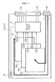
- FIG. 1 is a schematic functional block diagram of the battery module 11.
- each of battery modules is denoted by the "11A”, “11B”, “11C”... as a combination of the main Reference “11” assigned to the battery modules and the branch Reference “A”, “B”, “C” ..., to follow thereafter.
- the battery module when mentioned in general, is denoted by the main Reference “11” alone.
- SCI serial communication interfaces
- power source circuit terminal sections 19 battery packs 21, identifying information signal terminal sections 23 to be described later, as well as the battery modules.
- a battery module 11A which is equivalent to one of the “battery elements" according to the present invention, includes a DC power source circuit 12, a battery cell monitoring section 13, an identifying information signal terminal section 15a, a serial communication interface (SCI: Serial Communication Interface; hereinafter abbreviated as the "SCI") 17a, a power source circuit terminal section (hereinafter referred to as the "power”) 19a and a display 20.
- SCI Serial Communication Interface
- the DC power source circuit 12 includes a plurality of battery cells (for example, lithium ion secondary batteries) EC1, EC2, ..., ECn (where n is a natural number) connected in series.
- the DC power source circuit 12 has a positive terminal and a negative terminal connected to the power source circuit terminal section 19a for feeding to the outside direct-current power charged in the plurality of battery cells EC1, EC2, ..., ECn.
- the plurality of battery cells EC1, EC2, ..., ECn have respectively temperature sensors T1, T2, T3, ..., Tn for detecting the temperatures around the battery cells and voltage sensors V1, V2, V3, ..., Vn for detecting the voltages of the battery cells.
- the battery cell monitoring section 13 has the function of managing the plurality of battery cells EC1, EC2, ..., ECn. More specifically, the battery cell monitoring section 13 acquires values of the temperatures from the respective temperature sensors T1, T2, T3, ..., Tn and values of the voltages from the respective cell voltage sensors V1, V2, V3, ..., Vn and makes temperature correction to determine the state of charge (SOC) of each of the battery cells EC1, EC2, ..., ECn. Further, the battery cell monitoring section 13 determines whether the battery cells EC1, EC2, ..., ECn are overcharged or overdischarged based on the voltages thereof.
- SOC state of charge
- the identifying information signal terminal section 15a allows passage of a signal indicative of identifying information for uniquely identifying a battery module 11 which is equivalent to the "battery element" according to the present invention.
- the SCI 17a allows passage of a signal for information communication between the battery module 11 and a battery pack 21 which is equivalent to the "superordinate battery element” according to the present invention to which the battery module 11 belongs.
- the information for the communication between the battery module 11 and the battery pack 21 includes information indicative of values of the temperature and voltage and information indicative of the state of charge (SOC) of each of the battery cells EC1, EC2, ..., ECn.
- the power source circuit terminal section 19a allows passage of power; the direct-current power charged in the battery cells EC1, EC2, ..., ECn is fed to the outside through the power source circuit terminal section 19a while power is supplied from the outside through the power source circuit terminal section 19a to be accumulated in the plurality of battery cells EC1, EC2, ..., ECn.
- the display 20 has the function of displaying the state of operation of the battery module 11A.
- the battery module 11A configured as described above has a capacity of, but not limited to, for example, about 10Ah to 30Ah.
- the battery module 11A has, upon necessity, the functions of operations on the internal impedance and the state of health (SOH) of each of the battery cells EC1, EC2, ..., ECn health, the function of controlling balance between the voltages of the battery cells, and the function of detecting leakage of current inside the battery module 11A, as well as the function of an SOC operation.
- SOH state of health
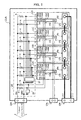
- FIG. 2 is a schematic functional block diagram of the battery pack 21.
- the battery pack 21A which is equivalent to one of the "battery elements" according to the present invention includes four battery modules 11A-11D, a SCI 17A, a power source circuit terminal section 19A, an identifying information signal terminal section 23A, and an identifying information setting section 25.
- the SCI 17A is connected to SCIs 17a-17d of the respective four battery modules 11A-11D.
- the SCI 17A allows passage of a signal for communication between the battery pack 21A and a battery system 31.
- the battery system 31 is equivalent to the "superordinate battery element" of which the battery pack 21A is a component. It should be noted that a communication path of a star type, a bus type, or the like type may be adopted properly to connect the SCIs 17a-17d.
- the power source circuit terminal section 19A is connected to the positive terminals and the negative terminals of power source circuit terminal sections 19a-19d of the respective four battery modules 11A-11D.
- the power source circuit terminal section 19A allows passage of power; the direct-current power charged in the plurality of battery modules 11A-11D is fed to the outside through the power source circuit terminal section 19A while power is supplied from the outside through the power source circuit terminal section 19A to be accumulated in the plurality of battery modules 11A-11D.
- the identifying information signal terminal section 23A allows passage, into an integral control section 35, of a signal indicative of identifying information for uniquely identifying each of the battery modules 11A-11D of the battery pack 21 A. It should be noted that the SCI 17A, the power source circuit terminal section 19A and the identifying information signal terminal section 23A are preferably spaced apart from each other to reduce effects of noises.
- the identifying information setting section 25 has the function of creating the signal indicative of the identifying information for uniquely identifying each of the battery modules 11A-11D of the battery pack 21A. More specifically, as shown in FIG. 2 , the identifying information setting section 25 includes a positive bus Vcc, a negative bus GND, a plurality of pull-up resistors R, and a first address setting section 27 and a second address setting section 29.
- Power for setting the identifying information to each of the battery modules 11A-11D may be supplied from the outside via the identifying information signal terminal section 23A, as shown in FIG. 2 .
- the power accumulated in the battery modules 11A-11D may be used.
- the first address setting section 27 and the second address setting section 29 may be, for example, a DIP switch, a short pin, or the like. With this configuration, the identifying information (address) assigned to each of the battery modules 11A-11D can be set to any value. In the case where there is no need to change the value of the address, the first address setting section 27 and the second address setting section 29 may be any circuits that allow fixed values to be set for the "H" and the "L", respectivley.
- the battery modules 11A-11D have respective identifying information signal terminal sections 15a-15d with first terminals 15a1-15d1 thereof connected to the negative bus GND.
- the identifying information signal terminal sections 15a-15d have second terminals 15a2-15d2 and third terminals 15a3-15d3 connected to the positive bus Vcc via pull-up resistors R.
- the second terminals 15a2-15d2 and the third terminals 15a3-15d3 are connected to the negative bus GND via the first address setting section 27.
- the identifying information signal terminal sections 15a-15d have fourth terminals 15a4-15d4 and fifth terminals 15a5-15d5 connected to the positive bus Vcc via the pull-up resistors R.
- the fourth terminals 15a4-15d4 and the fifth terminals 15a5-15d5 are connected to the negative bus GND via the second address setting section 29.
- the battery pack (equivalent to the "battery system” according to the present invention) 21A includes the four battery modules 11A-11D connected in series.
- the 2-bit address values "00", "01", "10” and "11" are assigned to first identifying information m1m2 on the potentials of the respective battery modules 11A-11D.
- the 2-bit address value "00" is assigned to second identifying information n1n2 on the superordinate battery element (battery pack 21A) to which the battery modules 11A-11D belong. It is the main feature of the present invention that the identifying information on each of the battery modules 11A-11D is made up of a combination of the first identifying information m1m2 on the potential of the one of the battery modules 11A-11D and the second identifying information n1n2 on the superordinate battery element to which the one of the battery modules 11A-11D belongs. This will be detailed later.
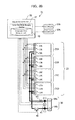
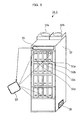
- FIG. 3A is an external view of the battery block accommodating unit 31.
- FIG. 3B is a schematic functional block diagram of the internal configuration of the battery block accommodating unit 31.
- the battery block accommodating unit 31 includes a battery block 33, the integral control section 35, a pair of fans 37a and 37b, a main power source terminal section 39, and a cabinet 32 for mounting these components.
- the battery block 33 includes four battery packs 21A-21D stacked on one another in the cabinet 32.
- the battery packs 21A-21D are accommodated in rectangular parallelepiped cases 34A-34D, respectively.
- the battery modules 11A-11D which are rectangular parallelepiped, are configured to be slidingly moved from one side of the case 34A along a longitudinal direction thereof so as to be mounted in places, respectively.
- connector members, not shown, of the case 34A and connector members of the battery modules 11A-11D are allowed to fit together for electrically connecting the battery modules 11A-11D and battery pack 21A when the battery modules 11A-11D are respectively mounted in places relative to the case 34A.
- the battery block 33 has the four battery packs 21A-21D connected in parallel by power source circuit terminal sections (powers) 19A-19D thereof connected to a positive terminal 39a and a negative terminal 39b of the main power source terminal section 39.
- a voltage sensor 41 for detecting a DC voltage of a main power source is disposed between a positive bus connected to the positive terminal 39a and a negative bus connected to the negative terminal 39b.
- a current sensor 43 is disposed on the positive bus connected to the positive terminal 39a for detecting a value of current flowing through that positive bus.
- an opening and closing switch 45 is disposed on the negative bus connected to the negative terminal 39b.
- the voltage sensor 41, the current sensor 43 and a movable contact of the opening and closing switch 45 are connected to the integral control section 35. Further, the SCIs 17A-17D and the identifying information signal terminal sections 23A-23D of the respective battery packs 21A-21D are connected to the integral control section 35. Moreover, the pair of fans 37a and 37b are connected to the integral control section 35. It should be noted that a communication path of a star type, a bus type, or the like type may be adopted properly to connect the SCIs 17A-17D, and the respective SCIs 17A-17D and the integral control section 35.
- the integral control section 35 is configured to include a connection mode managing section 47.
- the connection mode managing section 47 is configured to include a connection mode managing table 49. The contents of the connection mode managing table 49 will be described later.
- FIG. 4A is a conceptual diagram showing the details of the identifying information on the battery modules 11A-11D in the battery block 33 that is composed of the four battery packs 21A-21D connected in parallel.
- FIG. 4B is a conceptual diagram showing the details of the identifying information on the battery modules 11A-11D in the battery block 33 that is composed of a pair of assembled batteries connected in parallel, each assembled battery composed of two of the battery packs 21A-21D connected in series.
- a battery block 33-1 is composed of the four battery packs 21A-21D connected in parallel between the positive terminal 39a and the negative terminal 39b.
- each battery pack serving as an assembled battery composed of a plurality of battery modules connected in series
- each battery module is denoted by the "11A00", “11B00", “11C00”... as a combination of the main Reference “11A”, “11B”, “11C”, “11D”... assigned to the battery module of each assembled battery and branch Reference “00", "01", “10", “11” to follow thereafter.
- the battery module when mentioned in general, is denoted by the main Reference"11A", “11B”, “11C”, “11D”....
- the same value "00” is assigned to the first identifying information m1m2 on battery modules 11A00-11A11, of the battery modules 11A-11D serving as the "battery elements", having the same first potential “00” (See a row direction relating to the "00” in FIG. 4A ).
- the same value "01” is assigned to the first identifying information m1m2 on battery modules 11B00-11B11 having the same second potential “01” (See the row direction relating to the "01” in FIG. 4A ).
- the same value “10” is assigned to the first identifying information m1m2 on battery modules 11C00-11C11 having the same third potential “10” (See the row direction relating to the "10” in FIG. 4A ).
- the same value "11” is assigned to the first identifying information m1m2 on battery modules 11D00-11D11 having the same fourth potential “11” (See the row direction relating to the "11” in FIG. 4A ).
- the battery modules 11A00-11D00, of the battery modules 11A-11D serving as the "battery elements”, aligned in a column direction relating to the "00" in FIG. 4A belong to the same battery pack 21A which serves as the "superordinate battery element".
- the battery modules 11A01-11D01 aligned in the column direction relating to the "01" in FIG. 4A belong to the same battery pack 21B which serves as the "superordinate battery element”.
- the battery modules 11A10-11D10 aligned in the column direction relating to the "10” in FIG. 4A belong to the same battery pack 21C which serves as the "superordinate battery element”.
- the battery modules 11A11-11D11 aligned in the column direction relating to the "11” in FIG. 4A belong to the same battery pack 2 1 D which serves as the "superordinate battery element”.
- the same value (“00”, “01”, “10” and “11) is assigned to the second identifying information n1n2 on the battery modules 11A-11D aligned in the column direction.
- different values are assigned to the second identifying information n1n2 on battery modules that belong to different superordinate battery elements (battery packs).
- Table 1 shows the content of the connection mode managing table 49 (See FIG. 3B ) of the connection mode managing section 47 of the battery system according to First Embodiment.
- the identifying information on each of the battery modules 11A-11D according to First Embodiment is made up of a combination of a value assigned to the first identifying information m1m2 (2 bits) on the potential level of the battery module out of the four potential levels of the respective battery modules 11A-11D and a value assigned to the second identifying information n1n2 (2 bits) on the superordinate battery element to which the battery module belongs.
- the connection mode(s) between the battery modules 11A-11D can be uniquely grasped and managed based on the identifying information made up of the combination of a value of the first identifying information m1m2 (2 bits) on the potential level of the battery module out of the four potential levels of the respective battery modules 11A-11D and a value of the second identifying information n1n2 (2 bits) on the superordinate battery element to which the battery module belongs.
- the first identifying information m1m2 and the second identifying information n1n2 assigned to each of the battery modules 11 is referred to.
- connection mode between the battery modules 11 is the parallel connection.
- connection mode between the battery modules 11 is the serial connection.
- values assigned to the first identifying information m1m2 on the respective battery modules 11 are referred to in order to determine size relation of those values. It is assumed that the potential levels are arranged in ascending order(the values "00", “01”, “10” and “11” are assigned to a lower potential, an lower intermediate potential, an upper intermediate potential, and a higher potential, respectively when the first identifying information is made up of, for example, two bits).
- the battery system according to First Embodiment it is assumed that a serial communication between the SCIs 17a-17d of the respective battery modules 11A-11D using a same communication bus is conducted by sending a communication frame specifying a destination and a source using the identifying information of First Embodiment.
- the information communication between the battery modules 11A-11D is made with the first and second identifying information on the destination and the source uniquely specified. Therefore, the battery system according to First Embodiment enables smooth information communication between the battery modules 11A-11D without causing confusions.
- a battery block 33-2 is composed of a pair of assembled batteries connected in parallel between the positive terminal 39a and the negative terminal 39b.
- the two assembled batteries are composed of two pairs of battery packs (a pair of battery packs 21A and 21B) (a pair of battery packs 21C and 21D), respectively. Each pair of battery packs are connected in series.
- the above connection mode between the battery packs 21A-21D that compose the battery block 33-2 according to Second Embodiment that is, the connection mode between the battery packs 21A-21D connected in parallel, each of the battery packs 21A-21D composed of battery modules connected in series, is referred to in some cases as the "series parallel connection mode".
- the same value "000” is assigned to first identifying information m1m2m3 on the battery modules 11A00, 11A10, of the battery modules 11A-11D serving as the "battery elements", having the same first potential "000” (See a row direction relating to the "000” in FIG. 4B ).
- the same value "001” is assigned to the first identifying information m1m2m3on the battery modules 11B00, 11B10 having the same second potential "001” (See the row direction relating to the "001” in FIG. 4B ).
- the same value "010” is assigned to the first identifying information m1m2m3 on the battery modules 11C00, 11C10 having the same third potential “010” (See the row direction relating to the "010” in FIG. 4B ).
- the same value "011” is assigned to the first identifying information m1m2m3 on the battery modules 11D00, 11D10 having the same fourth potential “011” (See the row direction relating to the "011” in FIG. 4B ).
- the same value "100” is assigned to the first identifying information m1m2m3 on the battery modules 11A01, 11A11, of the battery modules 11A-11D serving as the "battery elements", having the same fifth potential "100” (See the row direction relating to the "100” in FIG. 4B ).
- the same value "101” is assigned to the first identifying information m1m2m3 on the battery modules 11B01, 11B11 having the same sixth potential "101” (See the row direction relating to the "101” in FIG. 4B ).
- the same value "110” is assigned to the first identifying information m1m2m3 on the battery modules 11C01, 11C11 having the same seventh potential “110” (See the row direction relating to the "110” in FIG. 4B ).
- the same value "111” is assigned to the first identifying information m1m2m3 on the battery modules 11D01, 11D11 having the same eighth potential “111” (See the row direction relating to the "111” in FIG. 4B ).
- the battery modules 11A00-11D00, of the battery modules 11A-11D serving as the "battery elements”, aligned in a column direction relating to the "00" in FIG. 4B belong to the same battery pack 21A which serves as the "superordinate battery element".
- the battery modules 11A01-11D01 aligned in the column direction relating to the "01" in FIG. 4B belong to the same battery pack 21B which serves as the "superordinate battery element”.
- the battery modules 11A10-11D10 aligned in the column direction relating to the "10” in FIG. 4B belong to the same battery pack 21C which serves as the "superordinate battery element”.
- the battery modules 11A11-11D11 aligned in the column direction relating to the "11” in FIG. 4B belong to the same battery pack 21D which serves as the "superordinate battery element”.
- Table 2 shows the content of the connection mode managing table 49 (See FIG. 3B ) according to Second Embodiment.
- the identifying information on each of the battery modules 11A-11D according to Second Embodiment is made up of a combination of a value assigned to the first identifying information m1m2m3 (3 bits) on the potential level of the battery module out of the eight potential levels of the battery modules 11A-11D and a value assigned to the second identifying information n1n2 (2 bits) on the superordinate battery element to which the battery module belongs.
- the connection mode(s) between the battery modules 11A-11D can be uniquely grasped and managed based on the identifying information made up of the combination of a value assigned to the first identifying information m1m2m3 (3 bits) on the potential level of the battery module out of the eight potential levels of the battery modules 11A-11D and a value assigned to the second identifying information n1n2 (2 bits) on the superordinate battery element to which the battery module belongs.
- the battery system according to Second Embodiment it is assumed that a serial communication between the SCIs 17a-17d of the respective battery modules 11A-11D using a same communication bus is conducted by sending a communication frame specifying a destination and a source using the identifying information of First Embodiment.
- the information communication between the battery modules 11A-11D is made with the first and second identifying information on the destination and the source uniquely specified. Therefore, like the battery system of First Embodiment, the battery system according to Second Embodiment enables smooth information communication between the battery modules 11A-11D without causing confusions.
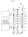
- FIG. 5A is a schematic view showing a procedure for grasping the connection mode between the pair of battery packs 21A and 21B connected in parallel that compose the battery block 33.
- FIG. 5B is a schematic view showing a procedure for grasping the connection mode between the pair of battery packs 21A and 21B connected in series that compose the battery block 33.
- FIG. 5C is a schematic view showing a procedure for grasping the connection mode between the pair of battery packs 21 A and 21 B connected in series that compose the battery block 33.
- the arrangement order of the pair of battery packs 21A and 21B is reversed from that in FIG. 5B .
- a battery block 33-3 is composed of a pair of a first battery pack 21A and a second battery pack 21B connected in parallel between the positive terminal 39a and the negative terminal 39b.
- the first battery pack 21A includes an A1 switch S A1 , an A1 connection point P A1 , the four battery modules 11A00-11D00, a B1 connection point P B1 and a B1 switch S B1 connected in this order between the positive terminal 39a and the negative terminal 39b.
- the A1 connection points P A1 and P B1 have respective potentials V A1 and V B1 , which are monitored by the integral control section 35.
- the second battery pack 21B includes an A2 switch S A2 , an A2 connection point P A2 , the four battery modules 11A01-11D01, a B1 connection point P B2 and a B1 switch S B2 connected in this order between the positive terminal 39a and the negative terminal 39b.
- the A2 connection points P A2 and P B2 have respective potentials V A2 and V B2 , which are monitored by the integral control section 35. It is assumed that the battery modules 11A00-11D00 of the first battery pack 21A have a capacity equal to that of the battery modules 11A01-11D01 of the second battery pack 21B.
- the battery block 33-3 according to Third Embodiment has all the switches S A1 , S B1 , S A2 and S B2 closed and that, as shown in FIG. 5A , the battery block 33-3 is composed of the first battery pack 21A and the second battery pack 21B connected in parallel.
- the potential V A1 of the A1 connection point P A1 and the potential V A2 of the A2 connection point P A2 are equal to each other
- the potential V B1 of the B1 connection point P B1 and the potential V B2 of the B2 connection point P B2 are equal to each other.
- the former and the latter are referred to as Conditions 1 and 2, respectively.
- Table 3 is the connection mode managing table 49 which shows how Conditions 1 and 2 correspond to the connection mode between the first battery pack 21A and the second battery pack 21B. [Table 3] Condition 1 Condition 2 Connection Mode Positioned Higher Positioned Lower V A1 ⁇ V A2 V B1 ⁇ V B2 Parallel Connection - -
- the integral control section 35 monitors the potential V A1 of the A1 connection point P A1 and the potential V B1 of the B1 connection point P B1 , and the potential V A2 of the A2 connection point P A2 and the potential V B2 of the B2 connection point P B2 , and determines whether or not Conditions 1 and 2 are satisfied in order to grasp and manage whether or not the first battery pack 21 A and the second battery pack 21 B are connected in parallel.
- the integral control section 35 may modify the identifying information on the battery modules 11A00-11D00 of the first battery pack 21A and the identifying information on the battery modules 11A01-11D01 of the second battery pack 21B according to the connection mode(s) between the first battery pack 21A and the second battery pack 21 B thus grasped and managed.
- the battery system of Third Embodiment enables grasp and management of whether or not the first battery pack 2 1 A and the second battery pack 21B are connected in parallel by a simple procedure of determining whether or not Conditions 1 and 2 are satisfied.
- a battery block 33-4 is composed of the pair of the first battery pack 21A and the second battery pack 21B connected in series between the positive terminal 39a and the negative terminal 39b.
- the first battery pack 21A includes the A1 switch S A1 , the A1 connection point P A1 , the four battery modules 11A00-11D00, the B1 connection point P B1 and the B1 switch S B1 connected in this order between a relay point P md and the negative terminal 39b.
- the potential V A1 of the A1 connection point P A1 and the potential V B1 of the B1 connection point P B1 are monitored by the integral control section 35.
- the second battery pack 21B includes the A2 switch S A2 , the A2 connection point P A2 , the four battery modules 11A01-11D01, the B1 connection point P B2 and the B1 switch S B2 connected in this order between the positive terminal 39a and the relay point P md .
- the potential V A2 of the A2 connection point P A2 and the potential V B2 of the B2 connection point P B2 are monitored by the integral control section 35.
- the battery block 33-4 according to Fourth Embodiment has all the switches S A1 , S B1 , S A2 and S B2 closed, that, as shown in FIG. 5B , the battery block 33-4 is composed of the first battery pack 21A and the second battery pack 21B connected in series and that the second battery pack 21B is positioned higher (has a higher potential) than the first battery pack 21A.
- Condition 3 Condition 4 Connection Mode Positioned Higher Positioned Lower V A1 ⁇ V B2 V A2 ⁇ V B1 Series Connection Second Battery Pack First Battery Pack
- the integral control section 35 monitors the potential V A1 of the A1 connection point P A1 and the potential V B2 of the B2 connection point P B2 , and the potential V A2 of the A2 connection point P A2 and the potential V B1 of the B1 connection point P B1 , and determines whether or not Conditions 3 and 4 are satisfied in order to grasp and manage whether or not the first battery pack 21A and the second battery pack 21B are connected in series and the relative positional relationship between the first battery pack 21A and the second battery pack 21B (which of the first battery pack 21A and the second battery pack 21B is positioned higher).
- the integral control section 35 may modify the identifying information on each of the battery modules 11A00-11D00 of the first battery pack 21A and the identifying information on each of the battery modules 11A01-11D01 of the second battery pack 21B according to the connection mode between the first battery pack 21A and the second battery pack 21B thus grasped and managed.
- the battery system of Fourth Embodiment enables grasp and management of whether or not the first battery pack 2 1 A and the second battery pack 21B are connected in series and of the relative positional relationship between the first battery pack 21A and of the second battery pack 21B (which of the first battery pack 21A and the second battery pack 21B is positioned higher) by a simple procedure of determining whether or not Conditions 3 and 4 are satisfied.
- a battery block 33 of Fifth Embodiment shown in FIG. 5C is composed of the pair of the first battery pack 21A and the second battery pack 21B connected in series between the positive terminal 39a and the negative terminal 39b.
- the arrangement order of the first battery pack 21A and the second battery pack 21B (which of the first battery pack 21A and the second battery pack 21B is positioned higher) is reversed from that in Fourth Embodiment.
- the first battery pack 21A includes the A1 switch S A1 , the A1 connection point P A1 , the four battery modules 11A00-11D00, the B1 connection point P B1 and the B1 switch S B1 connected in this order between the positive terminal 39a and the relay point P md .
- the potential V A1 of the A1 connection point P A1 and the potential V B1 of the B1 connection point P B1 are monitored by the integral control section 35.
- the second battery pack 21B includes the A2 switch S A2 , the A2 connection point P A2 , the four battery modules 11A01-11D01, the B1 connection point P B2 and the B1 switch S B2 connected in this order between the relay point P md and the negative terminal 39b.
- the potential V A2 of the A2 connection point P A2 and the potential V B2 of the B2 connection point P B2 are monitored by the integral control section 35. It is assumed that the battery modules 11A00-11D00 of the first battery pack 21A have a capacity equal to that of the battery modules 11A01-11D01 of the second battery pack 21B.
- the battery block 33-5 according to Fifth Embodiment has all the switches S A1 , S B1 , S A2 and S B2 closed, that as shown in FIG. 5C , the battery block 33-5 is composed of the first battery pack 21A and the second battery pack 21B connected to each other in series and that the first battery pack 21A is positioned higher (has a higher potential) than the second battery pack 21B.
- Condition 5 is the connection mode managing table 49 which shows how Conditions 5 and 6 correspond to the connection mode between the first battery pack 21A and the second battery pack 21B. [Table 5] Condition 5 Condition 6 Connection Mode Positioned Higher Positioned Lower V B1 ⁇ V A2 V B2 ⁇ V A1 Series Connection First Battery Pack Second Battery Pack
- the integral control section 35 monitors the potential V B1 of the B1 connection point P B1 and the potential V A2 of the A2 connection point P A2 , and the potential V B2 of the B2 connection point P B2 and the potential V A1 of the A1 connection point P A1 , and determines whether or not Conditions 5 and 6 are satisfied in order to grasp and manage whether or not the first battery pack 21 A and the second battery pack 21B are connected in series and the relative positional relationship between the first battery pack 21 A and the second battery pack 2 1 B (which of the first battery pack 21 A and the second battery pack 21B is positioned higher).
- the integral control section 35 may modify the identifying information on each of the battery modules 11A00-11D00 of the first battery pack 21A and the identifying information on each of the battery modules 11A01-11D01 of the second battery pack 2 1 B according to the connection mode(s) between the first battery pack 21A and the second battery pack 21B thus grasped and managed.
- the battery system of Fifth Embodiment enables grasp and management of whether or not the first battery pack 21A and the second battery pack 21B are connected in series and of the relative positional relationship between the first battery pack 21A and the second battery pack 21B (which of the first battery pack 21A and the second battery pack 21B is positioned higher) by a simple procedure of determining whether or not Conditions 5 and 6 are satisfied.
- the first identifying information m1m2 may be stored in an information medium in the form of, for example, IP addresses, one- or two-dimensional bar codes, IC tag data and GPS positioning data, or any combination thereof.
- the first identifying information m1m2 is set by relating values to their corresponding battery modules.
- the first identifying information m1m2 may be stored in an information medium in the form of, for example, one- or two-dimensional bar codes, serial numbers or the like, and adhesive seals carrying such one- or two-dimensional bar codes, serial numbers or the like may be attached to their corresponding battery modules.
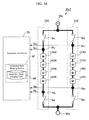
- FIG. 6 is a schematic view of a battery system provided with a separate reader mechanism according to a modification.
- the values assigned to the first identifying information m1m2 are represented by two-dimensional bar codes 51a-51d provided on the front faces of the respective battery modules 11A-11D.
- the battery block accommodating unit 3-2 according to the modification is provided with a two-dimensional bar-code scanner (information reader equipped with a camera) 53 for reading out the values of the first identifying information m1m2.
- examples are given in which values to be assigned to the first identifying information m1m2 are determined based on the potentials of the respective battery modules 11A-11D.
- the present invention is not limited those examples.
- the value assigned to the first identifying information m1m2 on the battery module may be modified automatically according to the changed potential.
- each battery pack is composed of four battery modules which serve as the "battery elements".
- the present invention is not limited to those examples. There is no particular limitation on the upper limit of the number of "battery elements". If the number of "battery elements" is increased, the number of information bits for the first identifying information and second identifying information may be increased accordingly.
Landscapes
- Engineering & Computer Science (AREA)
- Manufacturing & Machinery (AREA)
- Chemical & Material Sciences (AREA)
- Chemical Kinetics & Catalysis (AREA)
- Electrochemistry (AREA)
- General Chemical & Material Sciences (AREA)
- Power Engineering (AREA)
- Physics & Mathematics (AREA)
- General Physics & Mathematics (AREA)
- Microelectronics & Electronic Packaging (AREA)
- Charge And Discharge Circuits For Batteries Or The Like (AREA)
- Secondary Cells (AREA)
- Battery Mounting, Suspending (AREA)
Abstract
[Abstract] A battery pack (21A) according to embodiments of the present invention comprises a plurality of battery modules (11A-11D) connected to each other in either one or both of a series connection mode and a parallel connection mode. An identifying information setting section (25) sets identifying information on each of the plurality of battery elements (11A-11D). A connection mode managing section (47) manages the connection mode between the plurality of battery elements (11A-11D) by using the identifying information set by the identifying information setting section (25). The identifying information on each of the plurality of battery elements (11A-11D) is made up of a combination of first identifying information on the potential of the one of the plurality of battery elements (11A-11D) and second identifying information on the battery pack (21A) serving as a superordinate battery element to which the one of the plurality of battery elements (11A-11D) belongs.
Description
- The present invention relates to a battery system including a plurality of battery elements connected to each other in either one or both of a series connection mode and a parallel connection mode.
- Examples of conventionally known battery systems include one composed of a plurality of battery elements connected in parallel, each of which is composed of a plurality of battery cells connected in series (See, for example, Patent Document 1). A battery system disclosed in
Patent Document 1 uses specific address information assigned to each of a plurality of battery elements for detecting the remaining battery capacity of each battery element. The battery system ofPatent Document 1 enables highly accurate management of the remaining battery capacities of the plurality of battery elements. - Patent Document 1: Japanese Unexamined Patent Application Publication No.
2009-14566 - In recent years, progress has been made in development and tentative introduction of large-scale battery systems used for energy storage purposes. As the range of applications of the battery systems widens, the battery systems have been demanded to have extendability to flexibly cope with various requests on voltage and current capacity.
- A measure to realize such extendability may be to establish connection mode(s) between a plurality of battery elements in accordance with predetermined voltage and current capacity. To establish such a battery system, it is important to grasp and manage the connection mode(s) between the plurality of battery elements. However, this is infeasible with the battery system of
Patent Document 1. - The present invention has been made in view of the above situation, and it is an object of the present invention to provide a battery system that enables grasp and management of connection mode(s) between a plurality of battery elements.
- It is an object of the present invention to provide a b battery system comprising a plurality of battery elements connected to each other in either one or both of a series connection mode and a parallel connection mode, the battery system further comprising: an identifying information setting section for setting identifying information on each of the plurality of battery elements; and a connection mode managing section for managing a connection mode between the plurality of battery elements by using the identifying information set by the identifying information setting section, the identifying information on each of the plurality of battery elements comprising a combination of first identifying information on a potential of the battery element and second identifying information on a superordinate battery element to which the battery element belongs.
- The battery system according to embodiments of the present invention enables grasp and management of connection mode(s) between a plurality of battery elements.
-
- [
FIG. 1 ] A schematic functional block diagram of a battery module, which is a component of a battery system according to an embodiment of the present invention. - [
FIG. 2 ] A schematic functional block diagram of a battery pack, which is a component of the battery system according to an embodiment of the present invention. - [
FIG. 3A ] An external view of the battery block accommodating unit for accommodating and storing the battery system according to an embodiment of the present invention. - [
FIG. 3B ] A schematic functional block diagram of the internal configuration of the battery block accommodating unit. - [
FIG. 4A ] A conceptual diagram showing the details of the identifying information on the battery modules (parallel connection). - [
FIG. 4B ] A conceptual diagram showing the details of the identifying information on the battery modules (series parallel connection). - [
FIG. 5A ] A schematic view showing a procedure for grasping the connection mode between the pair of battery packs connected in parallel that compose the battery block. - [
FIG. 5B ] A schematic view showing a procedure for grasping the connection mode between the pair of battery packs connected in series that compose the battery block. - [
FIG. 5C ] A schematic view showing a procedure for grasping the connection mode between the pair of battery packs connected in series that compose the battery block, the arrangement order of the pair of battery packs being reversed from that inFIG. 5B . - [
FIG. 6 ] A schematic view showing a procedure for reading out the identifying information from the outside of a battery block accommodating unit. - In the following paragraphs, detailed descriptions will be made of battery systems according to embodiments of the present invention with reference to the drawings.
- First, a description will be made of a
battery module 11, which is a component of a battery system according to an embodiment of the present invention with reference toFIG. 1. FIG. 1 is a schematic functional block diagram of thebattery module 11. - In the following description, each of battery modules is denoted by the "11A", "11B", "11C"... as a combination of the main Reference "11" assigned to the battery modules and the branch Reference "A", "B", "C" ..., to follow thereafter. The battery module, when mentioned in general, is denoted by the main Reference "11" alone. Such a system of notation is applied to serial communication interfaces (SCI) 17, power source circuit terminal sections 19, battery packs 21, identifying information signal terminal sections 23 to be described later, as well as the battery modules.
- As shown in
FIG. 1 , abattery module 11A, which is equivalent to one of the "battery elements" according to the present invention, includes a DCpower source circuit 12, a batterycell monitoring section 13, an identifying informationsignal terminal section 15a, a serial communication interface (SCI: Serial Communication Interface; hereinafter abbreviated as the "SCI") 17a, a power source circuit terminal section (hereinafter referred to as the "power") 19a and adisplay 20. - The DC
power source circuit 12 includes a plurality of battery cells (for example, lithium ion secondary batteries) EC1, EC2, ..., ECn (where n is a natural number) connected in series. The DCpower source circuit 12 has a positive terminal and a negative terminal connected to the power sourcecircuit terminal section 19a for feeding to the outside direct-current power charged in the plurality of battery cells EC1, EC2, ..., ECn. The plurality of battery cells EC1, EC2, ..., ECn have respectively temperature sensors T1, T2, T3, ..., Tn for detecting the temperatures around the battery cells and voltage sensors V1, V2, V3, ..., Vn for detecting the voltages of the battery cells. - The battery
cell monitoring section 13 has the function of managing the plurality of battery cells EC1, EC2, ..., ECn. More specifically, the batterycell monitoring section 13 acquires values of the temperatures from the respective temperature sensors T1, T2, T3, ..., Tn and values of the voltages from the respective cell voltage sensors V1, V2, V3, ..., Vn and makes temperature correction to determine the state of charge (SOC) of each of the battery cells EC1, EC2, ..., ECn. Further, the batterycell monitoring section 13 determines whether the battery cells EC1, EC2, ..., ECn are overcharged or overdischarged based on the voltages thereof. - The identifying information
signal terminal section 15a allows passage of a signal indicative of identifying information for uniquely identifying abattery module 11 which is equivalent to the "battery element" according to the present invention. TheSCI 17a allows passage of a signal for information communication between thebattery module 11 and a battery pack 21 which is equivalent to the "superordinate battery element" according to the present invention to which thebattery module 11 belongs. The information for the communication between thebattery module 11 and the battery pack 21 includes information indicative of values of the temperature and voltage and information indicative of the state of charge (SOC) of each of the battery cells EC1, EC2, ..., ECn. - The power source
circuit terminal section 19a allows passage of power; the direct-current power charged in the battery cells EC1, EC2, ..., ECn is fed to the outside through the power sourcecircuit terminal section 19a while power is supplied from the outside through the power sourcecircuit terminal section 19a to be accumulated in the plurality of battery cells EC1, EC2, ..., ECn. Thedisplay 20 has the function of displaying the state of operation of thebattery module 11A. - The
battery module 11A configured as described above has a capacity of, but not limited to, for example, about 10Ah to 30Ah. Thebattery module 11A has, upon necessity, the functions of operations on the internal impedance and the state of health (SOH) of each of the battery cells EC1, EC2, ..., ECn health, the function of controlling balance between the voltages of the battery cells, and the function of detecting leakage of current inside thebattery module 11A, as well as the function of an SOC operation. - Now, a description will be made of the battery pack 21 which is equivalent to the battery system according to an embodiment of the present invention with reference to
FIG. 2. FIG. 2 is a schematic functional block diagram of the battery pack 21. - As shown in
FIG. 2 , thebattery pack 21A which is equivalent to one of the "battery elements" according to the present invention includes fourbattery modules 11A-11D, aSCI 17A, a power sourcecircuit terminal section 19A, an identifying informationsignal terminal section 23A, and an identifyinginformation setting section 25. - As shown in
FIG. 2 , theSCI 17A is connected toSCIs 17a-17d of the respective fourbattery modules 11A-11D. TheSCI 17A allows passage of a signal for communication between thebattery pack 21A and abattery system 31. Thebattery system 31 is equivalent to the "superordinate battery element" of which thebattery pack 21A is a component.
It should be noted that a communication path of a star type, a bus type, or the like type may be adopted properly to connect theSCIs 17a-17d. - As shown in
FIG. 2 , the power sourcecircuit terminal section 19A is connected to the positive terminals and the negative terminals of power sourcecircuit terminal sections 19a-19d of the respective fourbattery modules 11A-11D. The power sourcecircuit terminal section 19A allows passage of power; the direct-current power charged in the plurality ofbattery modules 11A-11D is fed to the outside through the power sourcecircuit terminal section 19A while power is supplied from the outside through the power sourcecircuit terminal section 19A to be accumulated in the plurality ofbattery modules 11A-11D. - As shown in
FIG. 2 , the identifying informationsignal terminal section 23A allows passage, into anintegral control section 35, of a signal indicative of identifying information for uniquely identifying each of thebattery modules 11A-11D of thebattery pack 21 A.
It should be noted that theSCI 17A, the power sourcecircuit terminal section 19A and the identifying informationsignal terminal section 23A are preferably spaced apart from each other to reduce effects of noises. - The identifying
information setting section 25 has the function of creating the signal indicative of the identifying information for uniquely identifying each of thebattery modules 11A-11D of thebattery pack 21A. More specifically, as shown inFIG. 2 , the identifyinginformation setting section 25 includes a positive bus Vcc, a negative bus GND, a plurality of pull-up resistors R, and a firstaddress setting section 27 and a secondaddress setting section 29. - Power for setting the identifying information to each of the
battery modules 11A-11D may be supplied from the outside via the identifying informationsignal terminal section 23A, as shown inFIG. 2 . Alternatively, the power accumulated in thebattery modules 11A-11D may be used. - The first
address setting section 27 and the secondaddress setting section 29 may be, for example, a DIP switch, a short pin, or the like. With this configuration, the identifying information (address) assigned to each of thebattery modules 11A-11D can be set to any value. In the case where there is no need to change the value of the address, the firstaddress setting section 27 and the secondaddress setting section 29 may be any circuits that allow fixed values to be set for the "H" and the "L", respectivley. - The
battery modules 11A-11D have respective identifying informationsignal terminal sections 15a-15d with first terminals 15a1-15d1 thereof connected to the negative bus GND. The identifying informationsignal terminal sections 15a-15d have second terminals 15a2-15d2 and third terminals 15a3-15d3 connected to the positive bus Vcc via pull-up resistors R. The second terminals 15a2-15d2 and the third terminals 15a3-15d3 are connected to the negative bus GND via the firstaddress setting section 27. - The identifying information
signal terminal sections 15a-15d have fourth terminals 15a4-15d4 and fifth terminals 15a5-15d5 connected to the positive bus Vcc via the pull-up resistors R. The fourth terminals 15a4-15d4 and the fifth terminals 15a5-15d5 are connected to the negative bus GND via the secondaddress setting section 29. - Here, a schematic description will be made of the identifying information assigned to each of the
battery modules 11A-11D with reference toFIG. 2 . As shown inFIG. 2 , it is assumed that the battery pack (equivalent to the "battery system" according to the present invention) 21A includes the fourbattery modules 11A-11D connected in series. In this case, for example, the 2-bit address values "00", "01", "10" and "11" are assigned to first identifying information m1m2 on the potentials of therespective battery modules 11A-11D. - Further, the 2-bit address value "00" is assigned to second identifying information n1n2 on the superordinate battery element (
battery pack 21A) to which thebattery modules 11A-11D belong. It is the main feature of the present invention that the identifying information on each of thebattery modules 11A-11D is made up of a combination of the first identifying information m1m2 on the potential of the one of thebattery modules 11A-11D and the second identifying information n1n2 on the superordinate battery element to which the one of thebattery modules 11A-11D belongs. This will be detailed later. - A description will be made of a battery system for accommodating and storing the battery
block accommodating unit 31 according to an embodiment of the present invention with reference toFIGs. 3A and3B .FIG. 3A is an external view of the batteryblock accommodating unit 31.FIG. 3B is a schematic functional block diagram of the internal configuration of the batteryblock accommodating unit 31. - As shown in
FIGs. 3A and3B , the batteryblock accommodating unit 31 includes abattery block 33, theintegral control section 35, a pair offans terminal section 39, and acabinet 32 for mounting these components. As shown inFIG. 3A , thebattery block 33 includes fourbattery packs 21A-21D stacked on one another in thecabinet 32. - It should be noted that as shown in
FIG. 3A , the battery packs 21A-21D are accommodated inrectangular parallelepiped cases 34A-34D, respectively. Thebattery modules 11A-11D, which are rectangular parallelepiped, are configured to be slidingly moved from one side of thecase 34A along a longitudinal direction thereof so as to be mounted in places, respectively. With this configuration, connector members, not shown, of thecase 34A and connector members of thebattery modules 11A-11D are allowed to fit together for electrically connecting thebattery modules 11A-11D andbattery pack 21A when thebattery modules 11A-11D are respectively mounted in places relative to thecase 34A. - As shown in
FIG. 3B , thebattery block 33 has the fourbattery packs 21A-21D connected in parallel by power source circuit terminal sections (powers) 19A-19D thereof connected to apositive terminal 39a and anegative terminal 39b of the main power sourceterminal section 39. Avoltage sensor 41 for detecting a DC voltage of a main power source is disposed between a positive bus connected to thepositive terminal 39a and a negative bus connected to thenegative terminal 39b. Further, acurrent sensor 43 is disposed on the positive bus connected to thepositive terminal 39a for detecting a value of current flowing through that positive bus. Further, an opening and closingswitch 45 is disposed on the negative bus connected to thenegative terminal 39b. - The
voltage sensor 41, thecurrent sensor 43 and a movable contact of the opening and closingswitch 45 are connected to theintegral control section 35. Further, theSCIs 17A-17D and the identifying informationsignal terminal sections 23A-23D of the respective battery packs 21A-21D are connected to theintegral control section 35. Moreover, the pair offans integral control section 35.
It should be noted that a communication path of a star type, a bus type, or the like type may be adopted properly to connect theSCIs 17A-17D, and therespective SCIs 17A-17D and theintegral control section 35. - As shown in
FIG. 3B , theintegral control section 35 is configured to include a connectionmode managing section 47. As shown inFIG. 3B , in order to manage connection modes between thebattery modules 11A-11D serving as the "battery elements" and between the battery packs 21A-21D, the connectionmode managing section 47 is configured to include a connection mode managing table 49. The contents of the connection mode managing table 49 will be described later. - Now, a detailed description will be made of the identifying information on each of the
battery modules 11A-11D with reference toFIGs. 4A and4B .FIG. 4A is a conceptual diagram showing the details of the identifying information on thebattery modules 11A-11D in thebattery block 33 that is composed of the fourbattery packs 21A-21D connected in parallel.FIG. 4B is a conceptual diagram showing the details of the identifying information on thebattery modules 11A-11D in thebattery block 33 that is composed of a pair of assembled batteries connected in parallel, each assembled battery composed of two of the battery packs 21A-21D connected in series. - According to First Embodiment shown in
FIG. 4A , a battery block 33-1 is composed of the fourbattery packs 21A-21D connected in parallel between thepositive terminal 39a and thenegative terminal 39b.
In the following description, for explaining battery modules in battery packs connected in parallel, each battery pack serving as an assembled battery composed of a plurality of battery modules connected in series, each battery module is denoted by the "11A00", "11B00", "11C00"... as a combination of the main Reference "11A", "11B", "11C", "11D"... assigned to the battery module of each assembled battery and branch Reference "00", "01", "10", "11" to follow thereafter. The battery module, when mentioned in general, is denoted by the main Reference"11A", "11B", "11C", "11D".... - The same value "00" is assigned to the first identifying information m1m2 on battery modules 11A00-11A11, of the
battery modules 11A-11D serving as the "battery elements", having the same first potential "00" (See a row direction relating to the "00" inFIG. 4A ). Likewise, the same value "01" is assigned to the first identifying information m1m2 on battery modules 11B00-11B11 having the same second potential "01" (See the row direction relating to the "01" inFIG. 4A ). The same value "10" is assigned to the first identifying information m1m2 on battery modules 11C00-11C11 having the same third potential "10" (See the row direction relating to the "10" inFIG. 4A ). The same value "11" is assigned to the first identifying information m1m2 on battery modules 11D00-11D11 having the same fourth potential "11" (See the row direction relating to the "11" inFIG. 4A ). - On the other hand, the battery modules 11A00-11D00, of the
battery modules 11A-11D serving as the "battery elements", aligned in a column direction relating to the "00" inFIG. 4A belong to thesame battery pack 21A which serves as the "superordinate battery element". Likewise, the battery modules 11A01-11D01 aligned in the column direction relating to the "01" inFIG. 4A belong to thesame battery pack 21B which serves as the "superordinate battery element". Likewise, the battery modules 11A10-11D10 aligned in the column direction relating to the "10" inFIG. 4A belong to thesame battery pack 21C which serves as the "superordinate battery element". Likewise, the battery modules 11A11-11D11 aligned in the column direction relating to the "11" inFIG. 4A belong to the same battery pack 2 1 D which serves as the "superordinate battery element". - In other words, the same value ("00", "01", "10" and "11) is assigned to the second identifying information n1n2 on the
battery modules 11A-11D aligned in the column direction.
Here, different values are assigned to the second identifying information n1n2 on battery modules that belong to different superordinate battery elements (battery packs). - Table 1 shows the content of the connection mode managing table 49 (See
FIG. 3B ) of the connectionmode managing section 47 of the battery system according to First Embodiment. As shown in Table 1, the identifying information on each of thebattery modules 11A-11D according to First Embodiment is made up of a combination of a value assigned to the first identifying information m1m2 (2 bits) on the potential level of the battery module out of the four potential levels of therespective battery modules 11A-11D and a value assigned to the second identifying information n1n2 (2 bits) on the superordinate battery element to which the battery module belongs.[Table 1] Connection Mode Managing Table m1m2 n1n2 m1m2 n1n2 m1m2 n1n2 m1m2 n1n2 11 00 11 01 11 10 11 11 10 00 10 01 10 10 10 11 01 00 01 01 01 10 01 11 00 00 00 01 00 10 00 11 - According to the battery system of First Embodiment, the connection mode(s) between the
battery modules 11A-11D (the serial connection or parallel connection, and arrangement order of the battery modules) can be uniquely grasped and managed based on the identifying information made up of the combination of a value of the first identifying information m1m2 (2 bits) on the potential level of the battery module out of the four potential levels of therespective battery modules 11A-11D and a value of the second identifying information n1n2 (2 bits) on the superordinate battery element to which the battery module belongs. - More specifically, for determining whether the connection mode between the
battery modules 11 is a serial connection or a parallel connection, the first identifying information m1m2 and the second identifying information n1n2 assigned to each of thebattery modules 11 is referred to. - When the same value is assigned to the first identifying information m1m2 on the
battery modules 11 while different values are assigned to the second identifying information n1n2 thereon, it is determined that the connection mode between thebattery modules 11 is the parallel connection. - On the other hand, when different values are assigned to the first identifying information m1m2 on the
battery modules 11 while the same value is assigned to the second identifying information n1n2 thereon, it is determined that the connection mode between thebattery modules 11 is the serial connection. - Further, for determining the arrangement order of the
battery modules 11 when the connection mode between thebattery modules 11 is the serial connection, values assigned to the first identifying information m1m2 on therespective battery modules 11 are referred to in order to determine size relation of those values. It is assumed that the potential levels are arranged in ascending order(the values "00", "01", "10" and "11" are assigned to a lower potential, an lower intermediate potential, an upper intermediate potential, and a higher potential, respectively when the first identifying information is made up of, for example, two bits). - In this case, it is determined that a battery module with a greater value assigned to the first identifying information m1m2 thereon is positioned higher (has a higher potential) than a battery module with a smaller value assigned to the first identifying information m1m2 thereon. This procedure for determination is applied to Second Embodiment to Fifth Embodiment as well.
- In the battery system according to First Embodiment, it is assumed that a serial communication between the
SCIs 17a-17d of therespective battery modules 11A-11D using a same communication bus is conducted by sending a communication frame specifying a destination and a source using the identifying information of First Embodiment. In this case, the information communication between thebattery modules 11A-11D is made with the first and second identifying information on the destination and the source uniquely specified. Therefore, the battery system according to First Embodiment enables smooth information communication between thebattery modules 11A-11D without causing confusions. - According to Second Embodiment shown in
FIG. 4B , a battery block 33-2 is composed of a pair of assembled batteries connected in parallel between thepositive terminal 39a and thenegative terminal 39b. The two assembled batteries are composed of two pairs of battery packs (a pair ofbattery packs battery packs
It should be noted that the above connection mode between the battery packs 21A-21D that compose the battery block 33-2 according to Second Embodiment, that is, the connection mode between the battery packs 21A-21D connected in parallel, each of the battery packs 21A-21D composed of battery modules connected in series, is referred to in some cases as the "series parallel connection mode". - The same value "000" is assigned to first identifying information m1m2m3 on the battery modules 11A00, 11A10, of the
battery modules 11A-11D serving as the "battery elements", having the same first potential "000" (See a row direction relating to the "000" inFIG. 4B ). Likewise, the same value "001" is assigned to the first identifying information m1m2m3on the battery modules 11B00, 11B10 having the same second potential "001" (See the row direction relating to the "001" inFIG. 4B ). The same value "010" is assigned to the first identifying information m1m2m3 on the battery modules 11C00, 11C10 having the same third potential "010" (See the row direction relating to the "010" inFIG. 4B ). The same value "011" is assigned to the first identifying information m1m2m3 on the battery modules 11D00, 11D10 having the same fourth potential "011" (See the row direction relating to the "011" inFIG. 4B ). - Further, the same value "100" is assigned to the first identifying information m1m2m3 on the battery modules 11A01, 11A11, of the
battery modules 11A-11D serving as the "battery elements", having the same fifth potential "100" (See the row direction relating to the "100" inFIG. 4B ). Likewise, the same value "101" is assigned to the first identifying information m1m2m3 on the battery modules 11B01, 11B11 having the same sixth potential "101" (See the row direction relating to the "101" inFIG. 4B ). The same value "110" is assigned to the first identifying information m1m2m3 on the battery modules 11C01, 11C11 having the same seventh potential "110" (See the row direction relating to the "110" inFIG. 4B ).The same value "111" is assigned to the first identifying information m1m2m3 on the battery modules 11D01, 11D11 having the same eighth potential "111" (See the row direction relating to the "111" inFIG. 4B ). - On the other hand, the battery modules 11A00-11D00, of the
battery modules 11A-11D serving as the "battery elements", aligned in a column direction relating to the "00" inFIG. 4B belong to thesame battery pack 21A which serves as the "superordinate battery element". Likewise, the battery modules 11A01-11D01 aligned in the column direction relating to the "01" inFIG. 4B belong to thesame battery pack 21B which serves as the "superordinate battery element". Likewise, the battery modules 11A10-11D10 aligned in the column direction relating to the "10" inFIG. 4B belong to thesame battery pack 21C which serves as the "superordinate battery element". Likewise, the battery modules 11A11-11D11 aligned in the column direction relating to the "11" inFIG. 4B belong to thesame battery pack 21D which serves as the "superordinate battery element". - In other words, the same value ("00", "01", "10" and "11) is assigned to the second identifying information n1n2 on the
battery modules 11A-11D aligned in the column direction. - Table 2 shows the content of the connection mode managing table 49 (See
FIG. 3B ) according to Second Embodiment. As shown in Table 2, the identifying information on each of thebattery modules 11A-11D according to Second Embodiment is made up of a combination of a value assigned to the first identifying information m1m2m3 (3 bits) on the potential level of the battery module out of the eight potential levels of thebattery modules 11A-11D and a value assigned to the second identifying information n1n2 (2 bits) on the superordinate battery element to which the battery module belongs.[Table 2] Connection Mode Managing Table m1m2m3 n1n2 m1m2m3 n1n2 111 01 111 11 110 01 110 11 101 01 101 11 100 01 100 11 011 00 011 10 010 00 010 10 001 00 001 10 000 00 000 10 - According to the battery system of Second Embodiment, the connection mode(s) between the
battery modules 11A-11D (the serial connection or parallel connection, and arrangement order of the battery modules) can be uniquely grasped and managed based on the identifying information made up of the combination of a value assigned to the first identifying information m1m2m3 (3 bits) on the potential level of the battery module out of the eight potential levels of thebattery modules 11A-11D and a value assigned to the second identifying information n1n2 (2 bits) on the superordinate battery element to which the battery module belongs. - In the battery system according to Second Embodiment, it is assumed that a serial communication between the
SCIs 17a-17d of therespective battery modules 11A-11D using a same communication bus is conducted by sending a communication frame specifying a destination and a source using the identifying information of First Embodiment. In this case, the information communication between thebattery modules 11A-11D is made with the first and second identifying information on the destination and the source uniquely specified. Therefore, like the battery system of First Embodiment, the battery system according to Second Embodiment enables smooth information communication between thebattery modules 11A-11D without causing confusions. - Now, a description will be made of procedures for grasping the connection mode between the pair of
battery packs FIGs. 5A-5C .FIG. 5A is a schematic view showing a procedure for grasping the connection mode between the pair ofbattery packs battery block 33.FIG. 5B is a schematic view showing a procedure for grasping the connection mode between the pair ofbattery packs battery block 33.FIG. 5C is a schematic view showing a procedure for grasping the connection mode between the pair of battery packs 21 A and 21 B connected in series that compose thebattery block 33. InFIG. 5C , the arrangement order of the pair ofbattery packs FIG. 5B . - According to Third Embodiment shown in 5A, a battery block 33-3 is composed of a pair of a
first battery pack 21A and asecond battery pack 21B connected in parallel between thepositive terminal 39a and thenegative terminal 39b. - The
first battery pack 21A includes an A1 switch SA1, an A1 connection point PA1, the four battery modules 11A00-11D00, a B1 connection point PB1 and a B1 switch SB1 connected in this order between thepositive terminal 39a and thenegative terminal 39b. The A1 connection points PA1 and PB1 have respective potentials VA1 and VB1, which are monitored by theintegral control section 35. - The
second battery pack 21B includes an A2 switch SA2, an A2 connection point PA2, the four battery modules 11A01-11D01, a B1 connection point PB2 and a B1 switch SB2 connected in this order between thepositive terminal 39a and thenegative terminal 39b. The A2 connection points PA2 and PB2 have respective potentials VA2 and VB2, which are monitored by theintegral control section 35.
It is assumed that the battery modules 11A00-11D00 of thefirst battery pack 21A have a capacity equal to that of the battery modules 11A01-11D01 of thesecond battery pack 21B. - It is assumed that the battery block 33-3 according to Third Embodiment has all the switches SA1, SB1, SA2 and SB2 closed and that, as shown in
FIG. 5A , the battery block 33-3 is composed of thefirst battery pack 21A and thesecond battery pack 21B connected in parallel. - In this case, the potential VA1 of the A1 connection point PA1 and the potential VA2 of the A2 connection point PA2 are equal to each other, and the potential VB1 of the B1 connection point PB1 and the potential VB2 of the B2 connection point PB2 are equal to each other. Here, the former and the latter are referred to as
Conditions 1 and 2, respectively.
Table 3 is the connection mode managing table 49 which shows howConditions 1 and 2 correspond to the connection mode between thefirst battery pack 21A and thesecond battery pack 21B.[Table 3] Condition 1Condition 2 Connection Mode Positioned Higher Positioned Lower VA1 ≈VA2 VB1 ≈VB2 Parallel Connection - - - In short, the
integral control section 35 monitors the potential VA1 of the A1 connection point PA1 and the potential VB1 of the B1 connection point PB1, and the potential VA2 of the A2 connection point PA2 and the potential VB2 of the B2 connection point PB2, and determines whether or notConditions 1 and 2 are satisfied in order to grasp and manage whether or not thefirst battery pack 21 A and thesecond battery pack 21 B are connected in parallel. - Further, the
integral control section 35 may modify the identifying information on the battery modules 11A00-11D00 of thefirst battery pack 21A and the identifying information on the battery modules 11A01-11D01 of thesecond battery pack 21B according to the connection mode(s) between thefirst battery pack 21A and thesecond battery pack 21 B thus grasped and managed. - The battery system of Third Embodiment enables grasp and management of whether or not the first battery pack 2 1 A and the
second battery pack 21B are connected in parallel by a simple procedure of determining whether or notConditions 1 and 2 are satisfied. - According to Fourth Embodiment shown in
FIG. 5B , a battery block 33-4 is composed of the pair of thefirst battery pack 21A and thesecond battery pack 21B connected in series between thepositive terminal 39a and thenegative terminal 39b. - The
first battery pack 21A includes the A1 switch SA1, the A1 connection point PA1, the four battery modules 11A00-11D00, the B1 connection point PB1 and the B1 switch SB1 connected in this order between a relay point Pmd and thenegative terminal 39b. The potential VA1 of the A1 connection point PA1 and the potential VB1 of the B1 connection point PB1 are monitored by theintegral control section 35. - Further, the
second battery pack 21B includes the A2 switch SA2, the A2 connection point PA2, the four battery modules 11A01-11D01, the B1 connection point PB2 and the B1 switch SB2 connected in this order between thepositive terminal 39a and the relay point Pmd. The potential VA2 of the A2 connection point PA2 and the potential VB2 of the B2 connection point PB2 are monitored by theintegral control section 35. - It is assumed that the battery block 33-4 according to Fourth Embodiment has all the switches SA1, SB1, SA2 and SB2 closed, that, as shown in
FIG. 5B , the battery block 33-4 is composed of thefirst battery pack 21A and thesecond battery pack 21B connected in series and that thesecond battery pack 21B is positioned higher (has a higher potential) than thefirst battery pack 21A. - In this case, the potential VA1 of the A1 connection point PA1 and the potential VB2 of the B2 connection point PB2 are equal to each other, and the potential VA2 of the A2 connection point PA2 and the potential VB1 of the B1 connection point PB1 are different from each other. Here, the former and the latter are referred to as Conditions 3 and 4, respectively.
Table 4 is the connection mode managing table 49 which shows how Conditions 3 and 4 correspond to the connection mode between thefirst battery pack 21A and thesecond battery pack 21B.[Table 4] Condition 3 Condition 4 Connection Mode Positioned Higher Positioned Lower VA1 ≈VB2 VA2 ≠VB1 Series Connection Second Battery Pack First Battery Pack - In short, the
integral control section 35 monitors the potential VA1 of the A1 connection point PA1 and the potential VB2 of the B2 connection point PB2, and the potential VA2 of the A2 connection point PA2 and the potential VB1 of the B1 connection point PB1, and determines whether or not Conditions 3 and 4 are satisfied in order to grasp and manage whether or not thefirst battery pack 21A and thesecond battery pack 21B are connected in series and the relative positional relationship between thefirst battery pack 21A and thesecond battery pack 21B (which of thefirst battery pack 21A and thesecond battery pack 21B is positioned higher). - Further, the
integral control section 35 may modify the identifying information on each of the battery modules 11A00-11D00 of thefirst battery pack 21A and the identifying information on each of the battery modules 11A01-11D01 of thesecond battery pack 21B according to the connection mode between thefirst battery pack 21A and thesecond battery pack 21B thus grasped and managed. - The battery system of Fourth Embodiment enables grasp and management of whether or not the first battery pack 2 1 A and the
second battery pack 21B are connected in series and of the relative positional relationship between thefirst battery pack 21A and of thesecond battery pack 21B (which of thefirst battery pack 21A and thesecond battery pack 21B is positioned higher) by a simple procedure of determining whether or not Conditions 3 and 4 are satisfied. - Like the battery block 33-4 of Fourth Embodiment, a
battery block 33 of Fifth Embodiment shown inFIG. 5C is composed of the pair of thefirst battery pack 21A and thesecond battery pack 21B connected in series between thepositive terminal 39a and thenegative terminal 39b.
In Fifth Embodiment, however, the arrangement order of thefirst battery pack 21A and thesecond battery pack 21B (which of thefirst battery pack 21A and thesecond battery pack 21B is positioned higher) is reversed from that in Fourth Embodiment. - The
first battery pack 21A includes the A1 switch SA1, the A1 connection point PA1, the four battery modules 11A00-11D00, the B1 connection point PB1 and the B1 switch SB1 connected in this order between thepositive terminal 39a and the relay point Pmd. The potential VA1 of the A1 connection point PA1 and the potential VB1 of the B1 connection point PB1 are monitored by theintegral control section 35. - The
second battery pack 21B includes the A2 switch SA2, the A2 connection point PA2, the four battery modules 11A01-11D01, the B1 connection point PB2 and the B1 switch SB2 connected in this order between the relay point Pmd and thenegative terminal 39b. The potential VA2 of the A2 connection point PA2 and the potential VB2 of the B2 connection point PB2 are monitored by theintegral control section 35.
It is assumed that the battery modules 11A00-11D00 of thefirst battery pack 21A have a capacity equal to that of the battery modules 11A01-11D01 of thesecond battery pack 21B. - It is assumed that the battery block 33-5 according to Fifth Embodiment has all the switches SA1, SB1, SA2 and SB2 closed, that as shown in
FIG. 5C , the battery block 33-5 is composed of thefirst battery pack 21A and thesecond battery pack 21B connected to each other in series and that thefirst battery pack 21A is positioned higher (has a higher potential) than thesecond battery pack 21B. - In this case, the potential VB1 of the B1 connection point PB1 and the potential VA2 of the A2 connection point PA2 are equal to each other, and the potential VB2 of the B2 connection point PB2 and the potential VA1 of the A1 connection point PA1 are different from each other. Here, the former and the latter are referred to as Conditions 5 and 6, respectively.
Table 5 is the connection mode managing table 49 which shows how Conditions 5 and 6 correspond to the connection mode between thefirst battery pack 21A and thesecond battery pack 21B.[Table 5] Condition 5 Condition 6 Connection Mode Positioned Higher Positioned Lower VB1 ≈VA2 VB2 ≠VA1 Series Connection First Battery Pack Second Battery Pack - In short, the
integral control section 35 monitors the potential VB1 of the B1 connection point PB1 and the potential VA2 of the A2 connection point PA2, and the potential VB2 of the B2 connection point PB2 and the potential VA1 of the A1 connection point PA1, and determines whether or not Conditions 5 and 6 are satisfied in order to grasp and manage whether or not thefirst battery pack 21 A and thesecond battery pack 21B are connected in series and the relative positional relationship between thefirst battery pack 21 A and the second battery pack 2 1 B (which of thefirst battery pack 21 A and thesecond battery pack 21B is positioned higher). - Further, the
integral control section 35 may modify the identifying information on each of the battery modules 11A00-11D00 of thefirst battery pack 21A and the identifying information on each of the battery modules 11A01-11D01 of the second battery pack 2 1 B according to the connection mode(s) between thefirst battery pack 21A and thesecond battery pack 21B thus grasped and managed. - The battery system of Fifth Embodiment enables grasp and management of whether or not the
first battery pack 21A and thesecond battery pack 21B are connected in series and of the relative positional relationship between thefirst battery pack 21A and thesecond battery pack 21B (which of thefirst battery pack 21A and thesecond battery pack 21B is positioned higher) by a simple procedure of determining whether or not Conditions 5 and 6 are satisfied. - While preferred embodiments of the invention have been described, such descriptions are for illustrative purposes only, and it is to be understood that changes and variations may be made without departing from the spirit and scope of the invention.
- In the embodiments, examples are given in which the first identifying information m1m2 is set by the identifying
information setting section 25. However, the present invention is not limited to those examples. The first identifying information m1m2 may be stored in an information medium in the form of, for example, IP addresses, one- or two-dimensional bar codes, IC tag data and GPS positioning data, or any combination thereof. - Further, in the embodiments, examples are given in which the first identifying information m1m2 is set by relating values to their corresponding battery modules. However, the present invention is not limited those examples. The first identifying information m1m2 may be stored in an information medium in the form of, for example, one- or two-dimensional bar codes, serial numbers or the like, and adhesive seals carrying such one- or two-dimensional bar codes, serial numbers or the like may be attached to their corresponding battery modules.
- In adopting the above-mentioned system for storing the first identifying information m1m2, there is a problem of how to read out values assigned to the first identifying information m1m2, which is solved by providing a separate reader mechanism for reading out the values assigned to the first identifying information m1m2.
FIG. 6 is a schematic view of a battery system provided with a separate reader mechanism according to a modification. In a battery block accommodating unit 3-2 according to the modification, as shown inFIG. 6 , the values assigned to the first identifying information m1m2 are represented by two-dimensional bar codes 51a-51d provided on the front faces of therespective battery modules 11A-11D. The battery block accommodating unit 3-2 according to the modification is provided with a two-dimensional bar-code scanner (information reader equipped with a camera) 53 for reading out the values of the first identifying information m1m2. - With this configuration, it is easy to check whether or not the identifying information (address signal) is set properly by scanning the two-dimensional bar-
code scanner 53 at the time of introduction, maintenance, maintenance replacement or the like of the battery system. - Further, in the embodiments, examples are given in which values to be assigned to the first identifying information m1m2 are determined based on the potentials of the
respective battery modules 11A-11D. However, the present invention is not limited those examples. When a battery module is changed in potential, the value assigned to the first identifying information m1m2 on the battery module may be modified automatically according to the changed potential. - In the embodiments, examples are given in which each battery pack is composed of four battery modules which serve as the "battery elements". However, the present invention is not limited to those examples. There is no particular limitation on the upper limit of the number of "battery elements". If the number of "battery elements" is increased, the number of information bits for the first identifying information and second identifying information may be increased accordingly.
-
- 11A-11D
- Battery Module (Battery Element)
- 13
- Battery Cell Monitoring Section
- 15a, 23A
- Identifying Information Signal Terminal Section
- 17A
- SCI
- 19A
- Power Source Circuit Terminal Section
- 21A-21D
- Battery Pack (Battery System)
- 25
- Identifying Information Setting Section
- 31
- Battery Block Accommodating Unit
- 3-2
- Battery Block Accommodating Unit according to Modification
- 33-1
- Battery Block according to First Embodiment
- 33-2
- Battery Block according to Second Embodiment
- 33-3
- Battery Block according to Third Embodiment
- 33-4
- Battery Block according to Fourth Embodiment
- 33-5
- Battery Block according to Fifth Embodiment
- 35
- Integral Control Section
- 47
- Connection Mode Managing Section
- 49
- Connection Mode Managing Table
- EC1, EC2, ..., ECn
- Battery Cell
Claims (7)
- A battery system comprising a plurality of battery elements connected to each other in either one or both of a series connection mode and a parallel connection mode, the battery system further comprising:an identifying information setting section for setting identifying information on each of the plurality of battery elements; anda connection mode managing section for managing a connection mode between the plurality of battery elements by using the identifying information set by the identifying information setting section,the identifying information on each of the plurality of battery elements comprising a combination of first identifying information on a potential of the battery element and second identifying information on a superordinate battery element to which the battery element belongs.
- The battery system of Claim 1, wherein a same value is assigned to the first identifying information on battery elements having a substantially same potential.
- The battery system of Claim 1, wherein a same value is assigned to the second identifying information on battery elements belonging to a same superordinate battery element.
- The battery system of Claim 3, wherein different values are assigned to the second identifying information on battery elements belonging to different superordinate battery elements.
- The battery system of Claim 3, wherein the connection mode managing section grasps the battery elements belonging to the same superordinate battery element by using the second identifying information, and grasps a connection mode between the gasped battery elements by using the first identifying information to manage the connection mode between the plurality of battery elements.
- The battery system of Claim 1, wherein the first identifying information is stored in any one of information media in the form of an IP address, a one- or two-dimensional bar code, IC tag data and GPS positioning data or any combination thereof.
- The battery system of Claim 1, wherein when the potential of a battery element is changed, a value of first identifying information of the battery element is modified according to the potential possessed by the battery element after the change of the potential.
Applications Claiming Priority (1)
| Application Number | Priority Date | Filing Date | Title |
|---|---|---|---|
| PCT/JP2011/067056 WO2013014758A1 (en) | 2011-07-27 | 2011-07-27 | Battery system |
Publications (1)
| Publication Number | Publication Date |
|---|---|
| EP2667446A1 true EP2667446A1 (en) | 2013-11-27 |
Family
ID=47600647
Family Applications (1)
| Application Number | Title | Priority Date | Filing Date |
|---|---|---|---|
| EP11817260.0A Withdrawn EP2667446A1 (en) | 2011-07-27 | 2011-07-27 | Battery system |
Country Status (5)
| Country | Link |
|---|---|
| US (1) | US9136566B2 (en) |
| EP (1) | EP2667446A1 (en) |
| JP (1) | JP5461686B2 (en) |
| CN (1) | CN103098294B (en) |
| WO (1) | WO2013014758A1 (en) |
Cited By (2)
| Publication number | Priority date | Publication date | Assignee | Title |
|---|---|---|---|---|
| GB2545700A (en) * | 2015-12-22 | 2017-06-28 | Poweroasis Ltd | Configurable battery module and system |
| EP3460498A4 (en) * | 2017-02-15 | 2019-08-07 | LG Chem, Ltd. | SYSTEM AND METHOD FOR ASSIGNING A SINGLE NUMBER TO A CELLULAR MODULE CONTROLLER |
Families Citing this family (16)
| Publication number | Priority date | Publication date | Assignee | Title |
|---|---|---|---|---|
| JP2014110198A (en) * | 2012-12-04 | 2014-06-12 | Toshiba Corp | Battery pack device, battery pack device inspection method and inspection program |
| JP2015008040A (en) * | 2013-06-24 | 2015-01-15 | 株式会社東芝 | Secondary battery device and module connection discrimination method |
| JP6187694B2 (en) * | 2014-06-10 | 2017-08-30 | 日立化成株式会社 | Battery panel |
| DE102015109168A1 (en) * | 2015-06-10 | 2016-12-15 | sonnen GmbH | Battery system for an electrical building energy supply network and method for checking an electrical energy storage |
| CN105516384B (en) * | 2015-11-27 | 2018-11-27 | 上海派能能源科技股份有限公司 | A kind of address distribution method and system of multiple battery modules |
| JP6414139B2 (en) * | 2016-05-24 | 2018-10-31 | トヨタ自動車株式会社 | Battery pack |
| JP6665746B2 (en) * | 2016-09-28 | 2020-03-13 | 日立化成株式会社 | Battery system |
| DE102018114462A1 (en) * | 2018-06-15 | 2019-12-19 | Liebherr-Components Biberach Gmbh | Energy storage device |
| JP6935793B2 (en) * | 2018-12-04 | 2021-09-15 | 株式会社デンソー | Battery system |
| KR102686901B1 (en) * | 2019-05-09 | 2024-07-22 | 주식회사 엘지에너지솔루션 | System for automatically assignign id to slave bms |
| KR20210030090A (en) * | 2019-09-09 | 2021-03-17 | 주식회사 엘지화학 | Battery rack and energy storage system comprising the battery rack |
| CN112599870A (en) * | 2020-12-17 | 2021-04-02 | 山东哈哎智能科技有限公司 | Battery communication conversion device |
| JP7634780B2 (en) * | 2021-12-29 | 2025-02-28 | 香港時代新能源科技有限公司 | METHOD FOR ADJUSTING OVERCURRENT IN ENERGY STORAGE SYSTEM AND ENERGY STORAGE SYSTEM |
| JP7535073B2 (en) * | 2022-03-18 | 2024-08-15 | いすゞ自動車株式会社 | Battery Management Unit |
| JP7396384B2 (en) * | 2022-03-18 | 2023-12-12 | いすゞ自動車株式会社 | battery management device |
| CN116826209A (en) * | 2023-07-04 | 2023-09-29 | 深圳市龙星辰电源有限公司 | Methods, systems, storage media and equipment for obtaining battery connections in battery packs |
Family Cites Families (15)
| Publication number | Priority date | Publication date | Assignee | Title |
|---|---|---|---|---|
| US6094053A (en) * | 1995-11-06 | 2000-07-25 | Ford Global Technologies, Inc. | Method and apparatus for identifying electronic circuits in a distributed electronic system |
| JP3893291B2 (en) * | 2002-01-10 | 2007-03-14 | パナソニック・イーブイ・エナジー株式会社 | Battery power unit for hybrid vehicles |
| JP4658795B2 (en) * | 2005-12-27 | 2011-03-23 | プライムアースEvエナジー株式会社 | Battery inspection device, voltage measuring instrument, and fixture |
| US7990101B2 (en) | 2006-05-15 | 2011-08-02 | A123 Systems, Inc. | Multi-configurable, scalable, redundant battery module with multiple fault tolerance |
| CN2927450Y (en) * | 2006-07-28 | 2007-07-25 | 天津乔迪电池科技有限公司 | Series and parallel switchover connector for charging lithium-battery of electric vehicle |
| JP4693761B2 (en) | 2006-12-25 | 2011-06-01 | 株式会社東芝 | Assembled battery system |
| JP4834573B2 (en) * | 2007-02-28 | 2011-12-14 | 矢崎総業株式会社 | Voltage detection device and voltage detection system |
| US9270133B2 (en) * | 2007-04-02 | 2016-02-23 | Linear Technology Corporation | Monitoring cells in energy storage system |
| JP5335207B2 (en) | 2007-07-05 | 2013-11-06 | キヤノン株式会社 | Electronics |
| JP5221468B2 (en) | 2009-02-27 | 2013-06-26 | 株式会社日立製作所 | Battery monitoring device |
| US8076016B2 (en) * | 2009-07-06 | 2011-12-13 | Tesla Motors, Inc. | Common mode voltage enumeration in a battery pack |
| US8483886B2 (en) * | 2009-09-01 | 2013-07-09 | Boston-Power, Inc. | Large scale battery systems and method of assembly |
| CN101860049A (en) * | 2010-04-28 | 2010-10-13 | 浙江绿源电动车有限公司 | Connection method of tree structure of matrix battery bank |
| US8525477B2 (en) * | 2010-07-15 | 2013-09-03 | O2Micro, Inc. | Assigning addresses to multiple cascade battery modules in electric or electric hybrid vehicles |
| CN101944582A (en) * | 2010-09-10 | 2011-01-12 | 鸥瑞智诺能源科技(北京)有限公司 | Novel stack battery connection method |
-
2011
- 2011-07-27 US US13/391,134 patent/US9136566B2/en active Active
- 2011-07-27 WO PCT/JP2011/067056 patent/WO2013014758A1/en not_active Ceased
- 2011-07-27 CN CN201180003348.0A patent/CN103098294B/en active Active
- 2011-07-27 EP EP11817260.0A patent/EP2667446A1/en not_active Withdrawn
- 2011-07-27 JP JP2012505907A patent/JP5461686B2/en active Active
Non-Patent Citations (1)
| Title |
|---|
| See references of WO2013014758A1 * |
Cited By (3)
| Publication number | Priority date | Publication date | Assignee | Title |
|---|---|---|---|---|
| GB2545700A (en) * | 2015-12-22 | 2017-06-28 | Poweroasis Ltd | Configurable battery module and system |
| EP3460498A4 (en) * | 2017-02-15 | 2019-08-07 | LG Chem, Ltd. | SYSTEM AND METHOD FOR ASSIGNING A SINGLE NUMBER TO A CELLULAR MODULE CONTROLLER |
| US11018382B2 (en) | 2017-02-15 | 2021-05-25 | Lg Chem, Ltd. | System and method for assigning unique number to cell module controller |
Also Published As
| Publication number | Publication date |
|---|---|
| CN103098294B (en) | 2015-06-17 |
| JPWO2013014758A1 (en) | 2015-02-23 |
| CN103098294A (en) | 2013-05-08 |
| JP5461686B2 (en) | 2014-04-02 |
| US9136566B2 (en) | 2015-09-15 |
| WO2013014758A1 (en) | 2013-01-31 |
| US20140147711A1 (en) | 2014-05-29 |
Similar Documents
| Publication | Publication Date | Title |
|---|---|---|
| EP2667446A1 (en) | Battery system | |
| US7274170B2 (en) | Battery pack control module | |
| AU2021230398C1 (en) | Apparatus, system and methods for batteries | |
| US8872477B2 (en) | Battery pack and line open detecting method thereof | |
| US7279867B2 (en) | Method for balancing cells or groups of cells in a battery pack | |
| EP2757627B1 (en) | Energy storage unit connection information acquiring apparatus | |
| US8227944B2 (en) | Vertical bus circuits | |
| US9024583B2 (en) | Battery pack with analog switch | |
| CN109256827A (en) | Secondary battery protection circuit, rechargeable battery protection integrated circuit and battery pack | |
| JP2008289296A (en) | Power supply | |
| US9411020B2 (en) | Battery pack and method of controlling the same | |
| US9935472B2 (en) | Battery pack | |
| US20190334356A1 (en) | Battery pack | |
| EP3667343B1 (en) | Apparatus and method for measuring voltage | |
| KR101036037B1 (en) | Secondary battery | |
| US7157881B1 (en) | Safety device for managing batteries | |
| JP2022508101A (en) | Battery management system | |
| CN214203910U (en) | Battery module and battery pack | |
| KR20210014343A (en) | A control method for uniform charing battery on serial connet to EV | |
| KR102125670B1 (en) | Balancing apparatus and the method using parallel connection of energy storage units | |
| CN116710791A (en) | Battery management device and method | |
| US12266966B2 (en) | Battery module and energy storage system including the same | |
| KR100461895B1 (en) | Method for Detecting and Correcting Error of Battery for Mobile Communication Device | |
| JP2008309747A (en) | Battery unit device | |
| JP2008043038A (en) | Portable terminal |
Legal Events
| Date | Code | Title | Description |
|---|---|---|---|
| PUAI | Public reference made under article 153(3) epc to a published international application that has entered the european phase |
Free format text: ORIGINAL CODE: 0009012 |
|
| 17P | Request for examination filed |
Effective date: 20120302 |
|
| AK | Designated contracting states |
Kind code of ref document: A1 Designated state(s): AL AT BE BG CH CY CZ DE DK EE ES FI FR GB GR HR HU IE IS IT LI LT LU LV MC MK MT NL NO PL PT RO RS SE SI SK SM TR |
|
| STAA | Information on the status of an ep patent application or granted ep patent |
Free format text: STATUS: THE APPLICATION HAS BEEN WITHDRAWN |
|
| 18W | Application withdrawn |
Effective date: 20140701 |