EP2667180A1 - Automatic analysis device - Google Patents
Automatic analysis device Download PDFInfo
- Publication number
- EP2667180A1 EP2667180A1 EP12737158.1A EP12737158A EP2667180A1 EP 2667180 A1 EP2667180 A1 EP 2667180A1 EP 12737158 A EP12737158 A EP 12737158A EP 2667180 A1 EP2667180 A1 EP 2667180A1
- Authority
- EP
- European Patent Office
- Prior art keywords
- light
- reaction
- light source
- reaction vessels
- sample
- Prior art date
- Legal status (The legal status is an assumption and is not a legal conclusion. Google has not performed a legal analysis and makes no representation as to the accuracy of the status listed.)
- Withdrawn
Links
Images

Classifications
-
- G—PHYSICS
- G01—MEASURING; TESTING
- G01N—INVESTIGATING OR ANALYSING MATERIALS BY DETERMINING THEIR CHEMICAL OR PHYSICAL PROPERTIES
- G01N21/00—Investigating or analysing materials by the use of optical means, i.e. using sub-millimetre waves, infrared, visible or ultraviolet light
- G01N21/17—Systems in which incident light is modified in accordance with the properties of the material investigated
- G01N21/47—Scattering, i.e. diffuse reflection
- G01N21/49—Scattering, i.e. diffuse reflection within a body or fluid
- G01N21/51—Scattering, i.e. diffuse reflection within a body or fluid inside a container, e.g. in an ampoule
-
- G—PHYSICS
- G01—MEASURING; TESTING
- G01N—INVESTIGATING OR ANALYSING MATERIALS BY DETERMINING THEIR CHEMICAL OR PHYSICAL PROPERTIES
- G01N21/00—Investigating or analysing materials by the use of optical means, i.e. using sub-millimetre waves, infrared, visible or ultraviolet light
- G01N21/17—Systems in which incident light is modified in accordance with the properties of the material investigated
- G01N21/47—Scattering, i.e. diffuse reflection
-
- G—PHYSICS
- G01—MEASURING; TESTING
- G01N—INVESTIGATING OR ANALYSING MATERIALS BY DETERMINING THEIR CHEMICAL OR PHYSICAL PROPERTIES
- G01N21/00—Investigating or analysing materials by the use of optical means, i.e. using sub-millimetre waves, infrared, visible or ultraviolet light
- G01N21/17—Systems in which incident light is modified in accordance with the properties of the material investigated
- G01N21/25—Colour; Spectral properties, i.e. comparison of effect of material on the light at two or more different wavelengths or wavelength bands
- G01N21/251—Colorimeters; Construction thereof
- G01N21/253—Colorimeters; Construction thereof for batch operation, i.e. multisample apparatus
-
- G—PHYSICS
- G01—MEASURING; TESTING
- G01N—INVESTIGATING OR ANALYSING MATERIALS BY DETERMINING THEIR CHEMICAL OR PHYSICAL PROPERTIES
- G01N35/00—Automatic analysis not limited to methods or materials provided for in any single one of groups G01N1/00 - G01N33/00; Handling materials therefor
- G01N35/02—Automatic analysis not limited to methods or materials provided for in any single one of groups G01N1/00 - G01N33/00; Handling materials therefor using a plurality of sample containers moved by a conveyor system past one or more treatment or analysis stations
- G01N35/025—Automatic analysis not limited to methods or materials provided for in any single one of groups G01N1/00 - G01N33/00; Handling materials therefor using a plurality of sample containers moved by a conveyor system past one or more treatment or analysis stations having a carousel or turntable for reaction cells or cuvettes
-
- G—PHYSICS
- G01—MEASURING; TESTING
- G01N—INVESTIGATING OR ANALYSING MATERIALS BY DETERMINING THEIR CHEMICAL OR PHYSICAL PROPERTIES
- G01N21/00—Investigating or analysing materials by the use of optical means, i.e. using sub-millimetre waves, infrared, visible or ultraviolet light
- G01N21/01—Arrangements or apparatus for facilitating the optical investigation
- G01N21/03—Cuvette constructions
- G01N2021/0325—Cells for testing reactions, e.g. containing reagents
-
- G—PHYSICS
- G01—MEASURING; TESTING
- G01N—INVESTIGATING OR ANALYSING MATERIALS BY DETERMINING THEIR CHEMICAL OR PHYSICAL PROPERTIES
- G01N21/00—Investigating or analysing materials by the use of optical means, i.e. using sub-millimetre waves, infrared, visible or ultraviolet light
- G01N21/17—Systems in which incident light is modified in accordance with the properties of the material investigated
- G01N21/47—Scattering, i.e. diffuse reflection
- G01N21/49—Scattering, i.e. diffuse reflection within a body or fluid
- G01N21/51—Scattering, i.e. diffuse reflection within a body or fluid inside a container, e.g. in an ampoule
- G01N2021/513—Cuvettes for scattering measurements
-
- G—PHYSICS
- G01—MEASURING; TESTING
- G01N—INVESTIGATING OR ANALYSING MATERIALS BY DETERMINING THEIR CHEMICAL OR PHYSICAL PROPERTIES
- G01N21/00—Investigating or analysing materials by the use of optical means, i.e. using sub-millimetre waves, infrared, visible or ultraviolet light
- G01N21/75—Systems in which material is subjected to a chemical reaction, the progress or the result of the reaction being investigated
- G01N21/77—Systems in which material is subjected to a chemical reaction, the progress or the result of the reaction being investigated by observing the effect on a chemical indicator
- G01N21/82—Systems in which material is subjected to a chemical reaction, the progress or the result of the reaction being investigated by observing the effect on a chemical indicator producing a precipitate or turbidity
- G01N2021/825—Agglutination
-
- G—PHYSICS
- G01—MEASURING; TESTING
- G01N—INVESTIGATING OR ANALYSING MATERIALS BY DETERMINING THEIR CHEMICAL OR PHYSICAL PROPERTIES
- G01N35/00—Automatic analysis not limited to methods or materials provided for in any single one of groups G01N1/00 - G01N33/00; Handling materials therefor
- G01N35/02—Automatic analysis not limited to methods or materials provided for in any single one of groups G01N1/00 - G01N33/00; Handling materials therefor using a plurality of sample containers moved by a conveyor system past one or more treatment or analysis stations
- G01N35/04—Details of the conveyor system
- G01N2035/0439—Rotary sample carriers, i.e. carousels
- G01N2035/0444—Rotary sample carriers, i.e. carousels for cuvettes or reaction vessels
-
- G—PHYSICS
- G01—MEASURING; TESTING
- G01N—INVESTIGATING OR ANALYSING MATERIALS BY DETERMINING THEIR CHEMICAL OR PHYSICAL PROPERTIES
- G01N2201/00—Features of devices classified in G01N21/00
- G01N2201/04—Batch operation; multisample devices
- G01N2201/0415—Carrusel, sequential
-
- G—PHYSICS
- G01—MEASURING; TESTING
- G01N—INVESTIGATING OR ANALYSING MATERIALS BY DETERMINING THEIR CHEMICAL OR PHYSICAL PROPERTIES
- G01N33/00—Investigating or analysing materials by specific methods not covered by groups G01N1/00 - G01N31/00
- G01N33/48—Biological material, e.g. blood, urine; Haemocytometers
- G01N33/483—Physical analysis of biological material
- G01N33/487—Physical analysis of biological material of liquid biological material
- G01N33/49—Blood
-
- G—PHYSICS
- G01—MEASURING; TESTING
- G01N—INVESTIGATING OR ANALYSING MATERIALS BY DETERMINING THEIR CHEMICAL OR PHYSICAL PROPERTIES
- G01N33/00—Investigating or analysing materials by specific methods not covered by groups G01N1/00 - G01N31/00
- G01N33/48—Biological material, e.g. blood, urine; Haemocytometers
- G01N33/483—Physical analysis of biological material
- G01N33/487—Physical analysis of biological material of liquid biological material
- G01N33/493—Physical analysis of biological material of liquid biological material urine
Definitions
- the present invention relates to automatic analyzers that examine substances in biological samples such as blood and urine and particularly to an automatic analyzer having a scattered-light measuring device.
- An example of an automatic analyzer used for clinical purposes is a biochemical analyzer that examines a particular substance in a biological sample (e.g., blood and urine) by using a reagent that exhibits color changes when reacting with that substance.
- a biological sample e.g., blood and urine
- Such an analyzer is designed to radiate light onto a sample-reagent mix and measure the intensity of transmissive light passing through the sample-reagent mix on a wavelength-by-wavelength basis, thereby measuring color changes quantitatively.
- a photodetector is disposed at an angle with respect to the axis of light radiated from a light source.
- the intensity of the scattered light varies if it passes through the surface of the sample-reagent mix or through a corner of the reaction vessel.
- the installation position of the photodetector within an automatic analyzer is limited because reaction vessels used are small and also because the analyzer often includes a thermostat tank for maintaining the temperatures of the reaction vessels at a constant value.
- An object of the invention is to provide an automatic analyzer having a scattered-light detecting optical system that allows relatively free design of reaction vessels in terms of their sizes and shapes.
- the invention provides an automatic analyzer configured as follows.
- the automatic analyzer includes: a reaction vessel in which a sample is caused to react with a reagent; a reaction disk on which to place reaction vessels in the form of a circle; a reaction disk rotating mechanism for rotating the reaction disk; a light source for radiating light to be measured onto one of the reaction vessels; and a photodetector for detecting transmissive light radiated from the light source and passing through a sample-reagent mix in the one of the reaction vessels.
- the automatic analyzer further includes an optical system for causing the light source to radiate light onto one of the reaction vessels at an angle with respect to a plane of the one of the reaction vessels.
- the automatic analyzer includes: a reaction vessel in which a sample is caused to react with a reagent; a reaction disk on which to place reaction vessels in the form of a circle; a reaction disk rotating mechanism for rotating the reaction disk; a light source for radiating light to be measured onto one of the reaction vessels; and a photodetector for detecting transmissive light radiated from the light source and passing through a sample-reagent mix in the one of the reaction vessels.
- the reaction vessels are cuboid-shaped or cylinder-shaped, and the automatic analyzer further includes an optical system for causing the light source to radiate light onto one of the reaction vessels at an angle with respect to a plane of the one of the reaction vessels.
- a light source is often disposed on an axis that passes through the center of a reaction vessel and is parallel to a longitude line of a reaction disk, so that measurement of transmissive light can also be performed.
- the common practice is to cause the light source to radiate light onto the reaction vessel at 90 degrees with respect to a surface of the reaction vessel.
- a transmissive-light detector is also disposed on the same axis. Under this method, the angle of scattered light relative to the optical axis of the light source cannot be increased too much.
- the present invention is characterized in that the optical axis of the radiated light is disposed at a particular angle so that the angle of scattered light relative to a horizontal or vertical plane can be made larger.
- an automatic analyzer having a scattered-light detecting optical system that allows relatively free design of reaction vessels in terms of their sizes and shapes.
- FIGS. 1 to 6 Embodiments of the present invention will now be described with reference to FIGS. 1 to 6 .
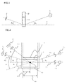
- FIG. 1 illustrates how to detect scattered light.
- a light source 1 radiates light 4 onto a reaction vessel 3, the light 4 is separated into transmissive light 5 and scattered light 6.
- a photodetector 2 is used to detect this scattered light. Note that while the following explanation is based on an assumption that the reaction vessel 3 is cuboid-shaped, it can instead be shaped into a cylinder or the like.
- FIG. 2 illustrates a positional relationship between a light source and a photodetector according to a conventional method of scattered light detection.
- the light source 1, the photodetector 2, and the reaction vessel 3 are now arranged on the same straight line. Also, the photodetector 2 is disposed at an angle ⁇ 0 with respect to a horizontal plane 7.
- FIG. 3 illustrates a positional relationship between the light source 1 and the photodetector 2 according to an embodiment of the present invention in which both the light source 1 and the photodetector 2 are disposed at angles with respect to the horizontal plane.
- the light source 1 and the photodetector 2 are disposed at angles ⁇ 1 and ⁇ 2 , respectively, relative to the horizontal plane 7.
- FIG. 4 illustrates how to reduce the amount of a sample-reagent mix according to the embodiment of the invention.
- reference symbol 1a represents a light source according to a conventional method while 1b represents a light source according to the present invention.
- reference symbol 2b represents a photodetector according to a conventional method while 2a represents a photodetector according to the present invention.
- FIG. 4 further shows an axis 7b disposed at an angle ⁇ 0 with respect to a horizontal plane, an axis 8a disposed at an angle ⁇ 1 with respect to the plane, and an axis 8b disposed at an angle ⁇ 2 with respect to the plane.
- the axis 7b represents a scattered-light detecting axis for the photodetector according to a conventional method while the axis 8b represents a scattered-light detecting axis for the photodetector according to the present invention.
- the axis 8a is an optical axis of the light source according to the present invention.
- the reaction vessel is square in cross section, and the width 14 of the reaction vessel 3 is 5 mm.
- the optical axis 8a of the radiated light and the scattered-light detecting axes 8b and 7b cross at a point 15 and that the distance 14 inside the reaction vessel (the width of the reaction vessel) is 2.5 mm.
- the liquid surface height can be in the range of 1 mm (2.5 mm ⁇ tan 22.5°) to 2.5 mm (2.5 mm ⁇ tan 45°).
- the amount of the sample-reagent mix can be reduced to the range of 25 ⁇ l to 62.5 ⁇ l. Accordingly, the running cost of reagents can be reduced approximately by half.
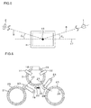
- FIG. 5 illustrates a positional relationship between the light source 1 and the photodetector 2 according to another embodiment of the invention in which both the light source 1 and the photodetector 2 are disposed at angles with respect to a vertical plane 17.
- the light source 1 and the photodetector 2 are disposed at angles ⁇ 1 and ⁇ 2 , respectively, relative to the vertical plane 17.
- the light source 1 and the photodetector 2 are disposed at angles with respect to the vertical plane 17, not to a horizontal plane, they can be installed at lower positions, thus reducing the overall height of the analyzer.
- This arrangement places an upper limit on measurement time if the analyzer is designed to measure transmissive light through or scattered light from a reaction vessel during the rotation of its reaction disk.
- the choice of reaction vessel sizes is also limited when smaller amount of samples and reagents need to be used.
- FIG. 6 illustrates an automatic analyzer to which the invention is applied.
- a reaction vessel rinse mechanism 18 cleans reaction vessels by discharging and suctioning water or a detergent into and from the reaction vessels 3.
- a sample dispenser 19 suctions a sample from one of sample vessels 21 placed on a sample vessel setting table 20, transfers the sample to a sample dispensing position 22 of a reaction disk, and discharges the sample into one of the reaction vessels 3. After the sample discharge, the sample dispenser 19 is cleaned by a sample dispenser rinse mechanism 23.
- a reagent dispenser 24 suctions a reagent from one of reagent vessels 26 placed on a reagent vessel setting table 25, transfers the reagent to a reagent dispensing position 27 of the reaction disk, and discharges the reagent into the sample-containing reaction vessel 3.
- the reagent dispenser 24 is cleaned by a reagent dispenser rinse mechanism 28.
- the sample to be examined and the reagent are mixed by a stirring mechanism 29, which is cleaned by a stirring mechanism rinse mechanism 30 after the mixing.
- a transmissive-light measuring unit 31 measures the absorbance of the sample-reagent mix contained within the reaction vessel 3 while a scattered-light measuring unit 32 measures scattered light generated from the sample-reagent mix contained within the reaction vessel 3. All of the above operations including the measurement of transmissive light and scattered light are performed while the reaction disk 33 is being operated.
Landscapes
- Physics & Mathematics (AREA)
- Chemical & Material Sciences (AREA)
- Biochemistry (AREA)
- Health & Medical Sciences (AREA)
- Life Sciences & Earth Sciences (AREA)
- Analytical Chemistry (AREA)
- General Health & Medical Sciences (AREA)
- General Physics & Mathematics (AREA)
- Immunology (AREA)
- Pathology (AREA)
- Chemical Kinetics & Catalysis (AREA)
- Spectroscopy & Molecular Physics (AREA)
- Investigating Or Analysing Materials By Optical Means (AREA)
- Automatic Analysis And Handling Materials Therefor (AREA)
- Investigating Or Analysing Materials By The Use Of Chemical Reactions (AREA)
Abstract
Description
- The present invention relates to automatic analyzers that examine substances in biological samples such as blood and urine and particularly to an automatic analyzer having a scattered-light measuring device.
- An example of an automatic analyzer used for clinical purposes is a biochemical analyzer that examines a particular substance in a biological sample (e.g., blood and urine) by using a reagent that exhibits color changes when reacting with that substance. Such an analyzer is designed to radiate light onto a sample-reagent mix and measure the intensity of transmissive light passing through the sample-reagent mix on a wavelength-by-wavelength basis, thereby measuring color changes quantitatively.
- Other than such analyzers that examine transmissive light, there are also medical analyzers that measure the size or amount of particles in a sample using scattered light. Such analyzers detect, for example, solid substances floating in urine or perform an immunoassay by examining agglutination reactions of latex particles. Such analyzing methods are disclosed in
Patent Documents -
- Patent Document 1:
JP-2010-32505-A - Patent Document 2:
JP-2007-309765-A - To measure scattered light, a photodetector is disposed at an angle with respect to the axis of light radiated from a light source. However, when the light scattered from a sample-reagent mix in a reaction vessel is measured, the intensity of the scattered light varies if it passes through the surface of the sample-reagent mix or through a corner of the reaction vessel. To ensure consistent measurements, it is therefore desired to measure only the scattered light passing through the same plane of the reaction vessel. However, the installation position of the photodetector within an automatic analyzer is limited because reaction vessels used are small and also because the analyzer often includes a thermostat tank for maintaining the temperatures of the reaction vessels at a constant value.
- An object of the invention is to provide an automatic analyzer having a scattered-light detecting optical system that allows relatively free design of reaction vessels in terms of their sizes and shapes.
- To achieve the above object, the invention provides an automatic analyzer configured as follows.
- The automatic analyzer includes: a reaction vessel in which a sample is caused to react with a reagent; a reaction disk on which to place reaction vessels in the form of a circle; a reaction disk rotating mechanism for rotating the reaction disk; a light source for radiating light to be measured onto one of the reaction vessels; and a photodetector for detecting transmissive light radiated from the light source and passing through a sample-reagent mix in the one of the reaction vessels. The automatic analyzer further includes an optical system for causing the light source to radiate light onto one of the reaction vessels at an angle with respect to a plane of the one of the reaction vessels.
- The above description may also be represented as follows.
- The automatic analyzer includes: a reaction vessel in which a sample is caused to react with a reagent; a reaction disk on which to place reaction vessels in the form of a circle; a reaction disk rotating mechanism for rotating the reaction disk; a light source for radiating light to be measured onto one of the reaction vessels; and a photodetector for detecting transmissive light radiated from the light source and passing through a sample-reagent mix in the one of the reaction vessels. The reaction vessels are cuboid-shaped or cylinder-shaped, and the automatic analyzer further includes an optical system for causing the light source to radiate light onto one of the reaction vessels at an angle with respect to a plane of the one of the reaction vessels.
- In a conventional optical system for scattered light detection, a light source is often disposed on an axis that passes through the center of a reaction vessel and is parallel to a longitude line of a reaction disk, so that measurement of transmissive light can also be performed. In other words, when the reaction vessel is cuboid-shaped, the common practice is to cause the light source to radiate light onto the reaction vessel at 90 degrees with respect to a surface of the reaction vessel. A transmissive-light detector is also disposed on the same axis. Under this method, the angle of scattered light relative to the optical axis of the light source cannot be increased too much. This is because, when the angle of scattered light is increased excessively relative to a horizontal plane, the scattered light may collide with the boundary between the reaction vessel and the surface of a sample-reagent mix within the vessel or with a bottom corner of the vessel. In contrast, the present invention is characterized in that the optical axis of the radiated light is disposed at a particular angle so that the angle of scattered light relative to a horizontal or vertical plane can be made larger.
- In accordance with the invention, it is possible to provide an automatic analyzer having a scattered-light detecting optical system that allows relatively free design of reaction vessels in terms of their sizes and shapes.
-
-
FIG. 1 illustrates how to detect scattered light; -
FIG. 2 illustrates a positional relationship between a light source and a photodetector according to a conventional method of scattered light detection; -
FIG. 3 illustrates a positional relationship between a light source and a photodetector according to an embodiment of the present invention in which both the light source and the photodetector are disposed at angles with respect to a horizontal plane; -
FIG. 4 illustrates how to reduce the amount of a sample-reagent mix according to the embodiment of the invention; -
FIG. 5 illustrates a positional relationship between a light source and a photodetector according to another embodiment of the invention in which both the light source and the photodetector are disposed at angles with respect to a vertical plane; and -
FIG. 6 illustrates an entire configuration of an automatic analyzer according to a further embodiment of the invention. - Embodiments of the present invention will now be described with reference to
FIGS. 1 to 6 . -
FIG. 1 illustrates how to detect scattered light. When alight source 1 radiates light 4 onto areaction vessel 3, thelight 4 is separated intotransmissive light 5 and scattered light 6. Aphotodetector 2 is used to detect this scattered light. Note that while the following explanation is based on an assumption that thereaction vessel 3 is cuboid-shaped, it can instead be shaped into a cylinder or the like. -
FIG. 2 illustrates a positional relationship between a light source and a photodetector according to a conventional method of scattered light detection. Thelight source 1, thephotodetector 2, and thereaction vessel 3 are now arranged on the same straight line. Also, thephotodetector 2 is disposed at an angle θ0 with respect to ahorizontal plane 7. -
FIG. 3 illustrates a positional relationship between thelight source 1 and thephotodetector 2 according to an embodiment of the present invention in which both thelight source 1 and thephotodetector 2 are disposed at angles with respect to the horizontal plane. Thelight source 1 and thephotodetector 2 are disposed at angles θ1 and θ2, respectively, relative to thehorizontal plane 7. -
FIG. 4 illustrates how to reduce the amount of a sample-reagent mix according to the embodiment of the invention. In this figure, reference symbol 1a represents a light source according to a conventional method while 1b represents a light source according to the present invention. Also,reference symbol 2b represents a photodetector according to a conventional method while 2a represents a photodetector according to the present invention.FIG. 4 further shows anaxis 7b disposed at an angle θ0 with respect to a horizontal plane, an axis 8a disposed at an angle θ1 with respect to the plane, and an axis 8b disposed at an angle θ2 with respect to the plane. Theaxis 7b represents a scattered-light detecting axis for the photodetector according to a conventional method while the axis 8b represents a scattered-light detecting axis for the photodetector according to the present invention. The axis 8a is an optical axis of the light source according to the present invention. - When the angle θ0 is assumed to be the optimal angle for scattered light detection, the light source angle θ1 and the detection angle θ2 are determined such that θ1 + θ2 = θ0. Because the height of the surface of the sample-reagent mix is smallest when the optical axis θ1 of the radiated light is equal to the angle θ2 set for the scattered-light detector (when θ1 = θ2), the angle θ2 set for the scattered-light detector is equal to θ0/2.
- Assume, for example, that θ0 = 45°, the reaction vessel is square in cross section, and the width 14 of the
reaction vessel 3 is 5 mm. Further assume that the optical axis 8a of the radiated light and the scattered-light detecting axes 8b and 7b cross at apoint 15 and that the distance 14 inside the reaction vessel (the width of the reaction vessel) is 2.5 mm. In that case, the liquid surface height can be in the range of 1 mm (2.5 mm × tan 22.5°) to 2.5 mm (2.5 mm × tan 45°). - Because a cross section of the reaction vessel is 25 mm2 (5 mm × 5 mm), the amount of the sample-reagent mix can be reduced to the range of 25 µl to 62.5 µl. Accordingly, the running cost of reagents can be reduced approximately by half.
-
FIG. 5 illustrates a positional relationship between thelight source 1 and thephotodetector 2 according to another embodiment of the invention in which both thelight source 1 and thephotodetector 2 are disposed at angles with respect to a vertical plane 17. Thelight source 1 and thephotodetector 2 are disposed at angles θ1 and θ2, respectively, relative to the vertical plane 17. When thelight source 1 and thephotodetector 2 are disposed at angles with respect to the vertical plane 17, not to a horizontal plane, they can be installed at lower positions, thus reducing the overall height of the analyzer. This arrangement, however, places an upper limit on measurement time if the analyzer is designed to measure transmissive light through or scattered light from a reaction vessel during the rotation of its reaction disk. The choice of reaction vessel sizes is also limited when smaller amount of samples and reagents need to be used. -
FIG. 6 illustrates an automatic analyzer to which the invention is applied. - A reaction vessel rinse
mechanism 18 cleans reaction vessels by discharging and suctioning water or a detergent into and from thereaction vessels 3. Asample dispenser 19 suctions a sample from one ofsample vessels 21 placed on a sample vessel setting table 20, transfers the sample to asample dispensing position 22 of a reaction disk, and discharges the sample into one of thereaction vessels 3. After the sample discharge, thesample dispenser 19 is cleaned by a sample dispenser rinsemechanism 23. Areagent dispenser 24 suctions a reagent from one ofreagent vessels 26 placed on a reagent vessel setting table 25, transfers the reagent to areagent dispensing position 27 of the reaction disk, and discharges the reagent into the sample-containingreaction vessel 3. After the reagent discharge, thereagent dispenser 24 is cleaned by a reagent dispenser rinsemechanism 28. The sample to be examined and the reagent are mixed by astirring mechanism 29, which is cleaned by a stirring mechanism rinsemechanism 30 after the mixing. A transmissive-light measuring unit 31 measures the absorbance of the sample-reagent mix contained within thereaction vessel 3 while a scattered-light measuring unit 32 measures scattered light generated from the sample-reagent mix contained within thereaction vessel 3. All of the above operations including the measurement of transmissive light and scattered light are performed while thereaction disk 33 is being operated. -
- 1: Light source
- 1a: Light source before the present invention is executed
- 1b: Light source after the present invention is executed
- 2: Detector
- 2a: Detector after the present invention is executed
- 2b: Detector before the present invention is executed
- 3: Reaction vessel
- 4: Incident light
- 5: Transmissive light
- 6: Scattered light
- 7: Horizontal plane
- 7a: Horizontal plane
- 7b: Axis disposed at an angle θ0 with respect to a horizontal plane
- 8: Optical axis of a light source after the present invention is executed
- 8a: Axis disposed at an angle θ1 with respect to a horizontal plane
- 8b: Axis disposed at an angle θ2 with respect to a horizontal plane
- 11: Liquid surface height before the present invention is executed
- 12: Liquid surface height after the present invention is executed
- 13: Sample-reagent mix (latex particles included)
- 14: Width of a reaction vessel
- 15: Intersecting point between an optical axis and light detecting axes
- 16: Distance between an inner wall of a reaction vessel and the
intersecting point 15 between an optical axis and light detecting axes - 17: Vertical plane
- 18: Reaction vessel rinse mechanism
- 19: Sample dispenser
- 20: Sample vessel setting table
- 21: Sample vessel
- 22: Sample dispensing position on a reaction disk
- 23: Sample dispenser rinse mechanism
- 24: Reagent dispenser
- 25: Reagent vessel setting table
- 26: Reagent vessel
- 27: Reagent dispensing position on a reaction disk
- 28: Reagent dispenser rinse mechanism
- 29: Stirring mechanism
- 30: Stirring mechanism rinse mechanism
- 31: Transmissive-light measuring unit
- 32: Scattered-light measuring unit
- 33: Reaction disk
Claims (4)
- An automatic analyzer comprising:a reaction vessel in which a sample is caused to react with a reagent;a reaction disk on which to place reaction vessels in the form of a circle;a reaction disk rotating mechanism for rotating the reaction disk;a light source for radiating light to be measured onto one of the reaction vessels; anda photodetector for detecting transmissive light radiated from the light source and passing through a sample-reagent mix in the one of the reaction vessels,wherein the automatic analyzer further includes an optical system for causing the light source to radiate light onto one of the reaction vessels at an angle with respect to a plane of the one of the reaction vessels.
- An automatic analyzer comprising:a reaction vessel in which a sample is caused to react with a reagent;a reaction disk on which to place reaction vessels in the form of a circle;a reaction disk rotating mechanism for rotating the reaction disk;a light source for radiating light to be measured onto one of the reaction vessels; anda photodetector for detecting transmissive light radiated from the light source and passing through a sample-reagent mix in the one of the reaction vessels,wherein the reaction vessels are cuboid-shaped or cylinder-shaped, andthe automatic analyzer further includes an optical system for causing the light source to radiate light onto one of the reaction vessels at an angle with respect to a plane of the one of the reaction vessels.
- The automatic analyzer according to claim 1 or 2, wherein the photodetector is disposed at an angle with respect to an axis of the light radiated from the light source onto the one of the reaction vessels.
- The automatic analyzer according to claim 3, wherein an angle of the light radiated from the light source onto the one of the reaction vessels is equal to an angle between the photodetector and the one of the reaction vessels.
Applications Claiming Priority (2)
| Application Number | Priority Date | Filing Date | Title |
|---|---|---|---|
| JP2011010349 | 2011-01-21 | ||
| PCT/JP2012/051117 WO2012099215A1 (en) | 2011-01-21 | 2012-01-19 | Automatic analysis device |
Publications (2)
| Publication Number | Publication Date |
|---|---|
| EP2667180A1 true EP2667180A1 (en) | 2013-11-27 |
| EP2667180A4 EP2667180A4 (en) | 2014-06-25 |
Family
ID=46515834
Family Applications (1)
| Application Number | Title | Priority Date | Filing Date |
|---|---|---|---|
| EP12737158.1A Withdrawn EP2667180A4 (en) | 2011-01-21 | 2012-01-19 | AUTOMATIC ANALYSIS DEVICE |
Country Status (5)
| Country | Link |
|---|---|
| US (1) | US20130302212A1 (en) |
| EP (1) | EP2667180A4 (en) |
| JP (1) | JP5748782B2 (en) |
| CN (1) | CN103210297B (en) |
| WO (1) | WO2012099215A1 (en) |
Families Citing this family (7)
| Publication number | Priority date | Publication date | Assignee | Title |
|---|---|---|---|---|
| JP5939833B2 (en) * | 2012-02-24 | 2016-06-22 | 株式会社日立ハイテクノロジーズ | Automatic analyzer |
| CN103698502A (en) * | 2013-12-13 | 2014-04-02 | 黄家亨 | Reaction cup frame |
| JP6592401B2 (en) * | 2016-05-26 | 2019-10-16 | 株式会社日立ハイテクノロジーズ | Sample liquid level position measuring apparatus and sample liquid level position measuring method |
| JP6227068B1 (en) * | 2016-07-27 | 2017-11-08 | 浜松ホトニクス株式会社 | Sample container holding member, optical measurement device, and sample container arrangement method |
| CN106770913A (en) * | 2016-12-09 | 2017-05-31 | 中储粮成都粮食储藏科学研究所 | A kind of fatty acid value automatic tester |
| US11865270B2 (en) * | 2020-01-16 | 2024-01-09 | Starling Medical, Inc. | Bodily fluid management system |
| JP2024171553A (en) * | 2023-05-30 | 2024-12-12 | 株式会社島津製作所 | Liquid Injection Device |
Family Cites Families (24)
| Publication number | Priority date | Publication date | Assignee | Title |
|---|---|---|---|---|
| US4059405A (en) * | 1972-04-11 | 1977-11-22 | Damon Corporation | Method and apparatus for analysis of constituent carried in fibrous medium |
| JPS5639465A (en) * | 1979-09-10 | 1981-04-15 | Olympus Optical Co Ltd | Detecting method of immunological agglutination |
| EP0217000B1 (en) * | 1985-07-15 | 1991-01-23 | Abbott Laboratories | Reagent containment system for a clinical analyser |
| JPS6188158A (en) * | 1985-09-03 | 1986-05-06 | Olympus Optical Co Ltd | Automatic analysis instrument |
| JPS62282246A (en) * | 1986-05-30 | 1987-12-08 | Saac Kk | Method for measuring scattering luminous intensity |
| JPH0359123U (en) * | 1989-10-06 | 1991-06-11 | ||
| US5350697A (en) * | 1990-08-28 | 1994-09-27 | Akzo N.V. | Scattered light detection apparatus |
| JP3533502B2 (en) * | 1994-10-14 | 2004-05-31 | 株式会社日立製作所 | Automatic chemical analyzer |
| JP3059123U (en) * | 1998-11-16 | 1999-07-02 | 日機装株式会社 | Particle size distribution analyzer |
| US7061601B2 (en) * | 1999-07-02 | 2006-06-13 | Kla-Tencor Technologies Corporation | System and method for double sided optical inspection of thin film disks or wafers |
| EP1128185B8 (en) * | 2000-02-25 | 2009-08-19 | Hitachi, Ltd. | Mixing device for automatic analyzer |
| JP3704035B2 (en) * | 2000-08-31 | 2005-10-05 | 株式会社日立製作所 | Automatic analyzer |
| JP4446592B2 (en) * | 2000-12-25 | 2010-04-07 | シスメックス株式会社 | Liquid sample measurement unit and automatic liquid sample analyzer equipped with the same |
| US20040016686A1 (en) * | 2002-07-24 | 2004-01-29 | Wyatt Philip J. | Absolute measurement centrifuge |
| JP3928113B2 (en) * | 2003-03-10 | 2007-06-13 | 株式会社日立製作所 | Automatic chemical analyzer |
| GB0307756D0 (en) * | 2003-04-03 | 2003-05-07 | Suisse Electronique Microtech | Measuring the concentration and motility of light scattering particles |
| JP4598682B2 (en) * | 2006-01-23 | 2010-12-15 | 株式会社日立ハイテクノロジーズ | Automatic analyzer |
| JP4918281B2 (en) | 2006-05-18 | 2012-04-18 | シスメックス株式会社 | Urine component analyzer |
| JP2007322324A (en) * | 2006-06-02 | 2007-12-13 | Olympus Corp | Analyzer |
| JP4829716B2 (en) * | 2006-08-18 | 2011-12-07 | シスメックス株式会社 | Blood coagulation analyzer |
| US20090325315A1 (en) | 2008-06-30 | 2009-12-31 | Arkray, Inc. | Detection method of target substance, detection reagent used for the same, and the uses thereof |
| US8675187B2 (en) * | 2008-12-24 | 2014-03-18 | Hitachi High-Technologies Corporation | Photometer and analyzing system provided with photometer |
| JP2010175342A (en) * | 2009-01-28 | 2010-08-12 | Hitachi High-Technologies Corp | Automatic analyzer and reaction vessel |
| US8804114B2 (en) * | 2010-11-03 | 2014-08-12 | Pocared Diagnostics Ltd. | Optical cup |
-
2012
- 2012-01-19 EP EP12737158.1A patent/EP2667180A4/en not_active Withdrawn
- 2012-01-19 US US13/979,858 patent/US20130302212A1/en not_active Abandoned
- 2012-01-19 JP JP2012553769A patent/JP5748782B2/en active Active
- 2012-01-19 CN CN201280003598.9A patent/CN103210297B/en active Active
- 2012-01-19 WO PCT/JP2012/051117 patent/WO2012099215A1/en not_active Ceased
Also Published As
| Publication number | Publication date |
|---|---|
| WO2012099215A1 (en) | 2012-07-26 |
| US20130302212A1 (en) | 2013-11-14 |
| JP5748782B2 (en) | 2015-07-15 |
| CN103210297A (en) | 2013-07-17 |
| CN103210297B (en) | 2016-05-04 |
| EP2667180A4 (en) | 2014-06-25 |
| JPWO2012099215A1 (en) | 2014-06-30 |
Similar Documents
| Publication | Publication Date | Title |
|---|---|---|
| US20130302212A1 (en) | Automatic analyzer | |
| EP2799882B1 (en) | Automatic analysis device and detection method for measurement value abnormalities | |
| US12253536B2 (en) | Automatic analysis device and automatic analysis method | |
| EP3734288B1 (en) | Automated analyzer and automated analysis method | |
| JP4251627B2 (en) | Chemical analyzer and dispensing method thereof | |
| EP2587251B1 (en) | Automated analysis device and automated analysis method | |
| EP2587250B1 (en) | Automatic analysis device | |
| EP2650673B1 (en) | Automatic analytical apparatus | |
| WO2014002677A1 (en) | Automatic analysis device and test sample measurement method | |
| JP6567873B2 (en) | Automatic analyzer | |
| US9575085B2 (en) | Automatic analysis device | |
| EP3640647B1 (en) | Automated analysis device | |
| WO2016017294A1 (en) | Automatic analysis device | |
| JP7420976B2 (en) | Automatic analyzer and analysis method | |
| US11951469B2 (en) | Device for storing reagent containers on several planes | |
| JP6657016B2 (en) | Automatic analyzer |
Legal Events
| Date | Code | Title | Description |
|---|---|---|---|
| PUAI | Public reference made under article 153(3) epc to a published international application that has entered the european phase |
Free format text: ORIGINAL CODE: 0009012 |
|
| 17P | Request for examination filed |
Effective date: 20130821 |
|
| AK | Designated contracting states |
Kind code of ref document: A1 Designated state(s): AL AT BE BG CH CY CZ DE DK EE ES FI FR GB GR HR HU IE IS IT LI LT LU LV MC MK MT NL NO PL PT RO RS SE SI SK SM TR |
|
| DAX | Request for extension of the european patent (deleted) | ||
| A4 | Supplementary search report drawn up and despatched |
Effective date: 20140528 |
|
| RIC1 | Information provided on ipc code assigned before grant |
Ipc: G01N 33/49 20060101ALI20140522BHEP Ipc: G01N 33/493 20060101ALI20140522BHEP Ipc: G01N 21/51 20060101ALI20140522BHEP Ipc: G01N 35/04 20060101ALI20140522BHEP Ipc: G01N 21/25 20060101ALI20140522BHEP Ipc: G01N 21/01 20060101AFI20140522BHEP |
|
| STAA | Information on the status of an ep patent application or granted ep patent |
Free format text: STATUS: THE APPLICATION HAS BEEN WITHDRAWN |
|
| 18W | Application withdrawn |
Effective date: 20141009 |