EP2667129B1 - A home appliance with a hinge plate - Google Patents
A home appliance with a hinge plate Download PDFInfo
- Publication number
- EP2667129B1 EP2667129B1 EP13168641.2A EP13168641A EP2667129B1 EP 2667129 B1 EP2667129 B1 EP 2667129B1 EP 13168641 A EP13168641 A EP 13168641A EP 2667129 B1 EP2667129 B1 EP 2667129B1
- Authority
- EP
- European Patent Office
- Prior art keywords
- hinge plate
- home appliance
- assembly
- lateral
- housing
- Prior art date
- Legal status (The legal status is an assumption and is not a legal conclusion. Google has not performed a legal analysis and makes no representation as to the accuracy of the status listed.)
- Active
Links
- 238000001816 cooling Methods 0.000 claims description 7
- 238000000034 method Methods 0.000 claims description 4
- 230000008878 coupling Effects 0.000 description 3
- 238000010168 coupling process Methods 0.000 description 3
- 238000005859 coupling reaction Methods 0.000 description 3
- 238000003466 welding Methods 0.000 description 2
- 239000000853 adhesive Substances 0.000 description 1
- 230000001070 adhesive effect Effects 0.000 description 1
- 230000003247 decreasing effect Effects 0.000 description 1
- 230000000694 effects Effects 0.000 description 1
- 238000005304 joining Methods 0.000 description 1
- 238000004519 manufacturing process Methods 0.000 description 1
Images


Classifications
-
- F—MECHANICAL ENGINEERING; LIGHTING; HEATING; WEAPONS; BLASTING
- F25—REFRIGERATION OR COOLING; COMBINED HEATING AND REFRIGERATION SYSTEMS; HEAT PUMP SYSTEMS; MANUFACTURE OR STORAGE OF ICE; LIQUEFACTION SOLIDIFICATION OF GASES
- F25D—REFRIGERATORS; COLD ROOMS; ICE-BOXES; COOLING OR FREEZING APPARATUS NOT OTHERWISE PROVIDED FOR
- F25D23/00—General constructional features
- F25D23/02—Doors; Covers
- F25D23/028—Details
-
- E—FIXED CONSTRUCTIONS
- E05—LOCKS; KEYS; WINDOW OR DOOR FITTINGS; SAFES
- E05D—HINGES OR SUSPENSION DEVICES FOR DOORS, WINDOWS OR WINGS
- E05D5/00—Construction of single parts, e.g. the parts for attachment
- E05D5/02—Parts for attachment, e.g. flaps
- E05D5/04—Flat flaps
-
- E—FIXED CONSTRUCTIONS
- E05—LOCKS; KEYS; WINDOW OR DOOR FITTINGS; SAFES
- E05Y—INDEXING SCHEME ASSOCIATED WITH SUBCLASSES E05D AND E05F, RELATING TO CONSTRUCTION ELEMENTS, ELECTRIC CONTROL, POWER SUPPLY, POWER SIGNAL OR TRANSMISSION, USER INTERFACES, MOUNTING OR COUPLING, DETAILS, ACCESSORIES, AUXILIARY OPERATIONS NOT OTHERWISE PROVIDED FOR, APPLICATION THEREOF
- E05Y2600/00—Mounting or coupling arrangements for elements provided for in this subclass
- E05Y2600/50—Mounting methods; Positioning
- E05Y2600/52—Toolless
- E05Y2600/522—Axial stacking
-
- E—FIXED CONSTRUCTIONS
- E05—LOCKS; KEYS; WINDOW OR DOOR FITTINGS; SAFES
- E05Y—INDEXING SCHEME ASSOCIATED WITH SUBCLASSES E05D AND E05F, RELATING TO CONSTRUCTION ELEMENTS, ELECTRIC CONTROL, POWER SUPPLY, POWER SIGNAL OR TRANSMISSION, USER INTERFACES, MOUNTING OR COUPLING, DETAILS, ACCESSORIES, AUXILIARY OPERATIONS NOT OTHERWISE PROVIDED FOR, APPLICATION THEREOF
- E05Y2600/00—Mounting or coupling arrangements for elements provided for in this subclass
- E05Y2600/50—Mounting methods; Positioning
- E05Y2600/52—Toolless
- E05Y2600/53—Snapping
-
- E—FIXED CONSTRUCTIONS
- E05—LOCKS; KEYS; WINDOW OR DOOR FITTINGS; SAFES
- E05Y—INDEXING SCHEME ASSOCIATED WITH SUBCLASSES E05D AND E05F, RELATING TO CONSTRUCTION ELEMENTS, ELECTRIC CONTROL, POWER SUPPLY, POWER SIGNAL OR TRANSMISSION, USER INTERFACES, MOUNTING OR COUPLING, DETAILS, ACCESSORIES, AUXILIARY OPERATIONS NOT OTHERWISE PROVIDED FOR, APPLICATION THEREOF
- E05Y2600/00—Mounting or coupling arrangements for elements provided for in this subclass
- E05Y2600/60—Mounting or coupling members; Accessories therefor
- E05Y2600/626—Plates or brackets
-
- E—FIXED CONSTRUCTIONS
- E05—LOCKS; KEYS; WINDOW OR DOOR FITTINGS; SAFES
- E05Y—INDEXING SCHEME ASSOCIATED WITH SUBCLASSES E05D AND E05F, RELATING TO CONSTRUCTION ELEMENTS, ELECTRIC CONTROL, POWER SUPPLY, POWER SIGNAL OR TRANSMISSION, USER INTERFACES, MOUNTING OR COUPLING, DETAILS, ACCESSORIES, AUXILIARY OPERATIONS NOT OTHERWISE PROVIDED FOR, APPLICATION THEREOF
- E05Y2900/00—Application of doors, windows, wings or fittings thereof
- E05Y2900/30—Application of doors, windows, wings or fittings thereof for domestic appliances
- E05Y2900/308—Application of doors, windows, wings or fittings thereof for domestic appliances for ovens
-
- E—FIXED CONSTRUCTIONS
- E05—LOCKS; KEYS; WINDOW OR DOOR FITTINGS; SAFES
- E05Y—INDEXING SCHEME ASSOCIATED WITH SUBCLASSES E05D AND E05F, RELATING TO CONSTRUCTION ELEMENTS, ELECTRIC CONTROL, POWER SUPPLY, POWER SIGNAL OR TRANSMISSION, USER INTERFACES, MOUNTING OR COUPLING, DETAILS, ACCESSORIES, AUXILIARY OPERATIONS NOT OTHERWISE PROVIDED FOR, APPLICATION THEREOF
- E05Y2900/00—Application of doors, windows, wings or fittings thereof
- E05Y2900/30—Application of doors, windows, wings or fittings thereof for domestic appliances
- E05Y2900/31—Application of doors, windows, wings or fittings thereof for domestic appliances for refrigerators
-
- F—MECHANICAL ENGINEERING; LIGHTING; HEATING; WEAPONS; BLASTING
- F24—HEATING; RANGES; VENTILATING
- F24C—DOMESTIC STOVES OR RANGES ; DETAILS OF DOMESTIC STOVES OR RANGES, OF GENERAL APPLICATION
- F24C15/00—Details
- F24C15/02—Doors specially adapted for stoves or ranges
- F24C15/023—Mounting of doors, e.g. hinges, counterbalancing
-
- F—MECHANICAL ENGINEERING; LIGHTING; HEATING; WEAPONS; BLASTING
- F24—HEATING; RANGES; VENTILATING
- F24C—DOMESTIC STOVES OR RANGES ; DETAILS OF DOMESTIC STOVES OR RANGES, OF GENERAL APPLICATION
- F24C15/00—Details
- F24C15/08—Foundations or supports plates; Legs or pillars; Casings; Wheels
-
- F—MECHANICAL ENGINEERING; LIGHTING; HEATING; WEAPONS; BLASTING
- F25—REFRIGERATION OR COOLING; COMBINED HEATING AND REFRIGERATION SYSTEMS; HEAT PUMP SYSTEMS; MANUFACTURE OR STORAGE OF ICE; LIQUEFACTION SOLIDIFICATION OF GASES
- F25D—REFRIGERATORS; COLD ROOMS; ICE-BOXES; COOLING OR FREEZING APPARATUS NOT OTHERWISE PROVIDED FOR
- F25D2323/00—General constructional features not provided for in other groups of this subclass
- F25D2323/02—Details of doors or covers not otherwise covered
- F25D2323/024—Door hinges
Definitions
- the present invention relates to a home appliance having a body in cabinet form; a lateral panel of the body; a one-piece base tab at the bottom part of the lateral panel; and a hinge plate connected to the base tab.
- hinges are utilized connected to the cabinet body from the bottom and top of the door.
- the hinge plates provide the connection between the lateral panels of the home appliances and the hinges.
- the connection between the hinge plates and the lateral panel is provided by means of methods like welding, using connection member and riveting.
- a home appliance connection structure is illustrated.
- Said home appliance connection structure comprises a lower border strip, a hinge plate fixedly connected with the lower border strip, a side plate which is fixed with the hinge plate, and a lower hinge which is fixed to the lower border strip, the hinge plate and the side plate.
- the hinge plate and the side plate are riveted and assembled through rivets, and the lower border strip, the hinge plate and the side plate are fixed with the lower hinge through the rivets so that the assembling process is simple, and the cost is relatively low.
- a hinge assembly for the door of a home appliance comprises a hinge plate that is secured to a cabinet by passing a plurality of fasteners through the hinge plate.
- the hinge plate includes a load bearing surface supporting a pivot pin defining a pivot axis for the door.
- US 2009/179539 A1 discloses a refrigerator according to the preamble of claim 1, having a hinge plate which is coupled to a refrigerator cabinet by way of a coupling plate, whereas the coupling plate includes holes for use with fasteners. D1 also discloses that the coupling may be made in various other manners such as for example by adhesives, welding, snap fit or interference fit.
- US 2011/030410 A1 discloses a household appliance having a door to which a decorative plate is attached.
- the present invention relates to a novel hinge plate, in order to eliminate the abovementioned problems and to bring new advantages to the related technical field.
- the main object of the present invention is to provide a hinge plate where the production cost and the assembly duration are decreased and where the fixation and centering performance is improved during the assembly of the door to the body of the home appliance.
- the present invention is a home appliance having a body in cabinet form; a lateral panel of the body; a one-piece base tab at the bottom part of the lateral panel; and a hinge plate connected to the base tab.
- said home appliance is characterized by comprising at least one assembly gap configured so as to connect the hinge plate and the base tab horizontally by means of the snap-fit method, said assembly gap provided in the region where the base tab and the hinge plate are connected; said home appliance also comprising at least one connection tab disposed within the assembly gap.
- the assembly gap is provided on the hinge plate, and the connection tab is provided on the base tab so as to correspond to the assembly gap.
- the connection of the hinge plate to the lateral panel is provided.
- the base tab comprises a housing whereon the connection tab is embodied and the hinge plate comprises a housing passage opening through which the housing passes.
- the hinge plate comprises an assembly latch whereon the assembly gap is provided.
- a resilience is obtained while the assembly latch, is passing to the assembly gap of the connection tab.
- two channels are provided on both sides of the assembly latch, and two lateral edges are provided such that the housing is disposed to the channels.
- a rigid structure of the housing is provided.
- the hinge plate comprises a base and an assembly wall coinciding with the lateral panel at the continuation of the base.
- the strength of the hinge plate is improved.
- the housing Passage opening is embodied at the region where the base of the hinge plate and the assembly wall are intersecting.
- the housing and the assembly latch is aligned with ease.
- the hinge plate comprises a base and an assembly wall coinciding with the lateral panel at the continuation of the base.
- the strength of the hinge plate is improved.
- the housing passage opening is embodied at the region where the base of the hinge plate and the assembly wall are intersecting.
- the housing and the assembly latch is aligned with ease.
- the body is a heat-insulated body and the home appliance is a cooling device.
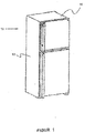
- FIG. 1 the representative view where a hinge plate (20) is assembled onto a lateral panel (12) on the body (11) of the cooling device (10) is given.
- a hinge plate (20) is assembled horizontally with respect to the lateral panel (12).
- the lateral panel (12) comprises a base tab (121); and two housings (122) provided on the base tab (121).
- the housings (122) comprise two each lateral edges (123) and one each inclined connection tab (124) provided in the middle sides thereof.
- the hinge plate (20) comprises a base (21); a lateral wall (23) having a tab (231) extending in a horizontal manner on the base (21); and an assembly wall (22) embodied so as to overlap with the lateral panel (12).
- the hinge plate (20) is cut in hypotenuse form on the side thereof corresponding to the assembly wall (22); and the hinge plate (20) has a form similar to a trapezoid.
- Two assembly latches (211) are embodied from the base (21) towards the assembly wall (22) such that there is a certain distance in between, and there are channels (213) on the lateral sides of the assembly latches (211).
- each housing passage opening (212) is embodied at the continuation of the assembly latches (211).
- the housing passage openings (212) are extending on the assembly wall (22) at a height where the housings (122) will enter.
- a vertical lateral bent part (125) of the lateral panel (12) and a vertical opening (126) is illustrated formed on the lateral bent part (125).
- a gap (not illustrated in the figure) is formed wherein the hinge plate (20) can be placed at the point where the base tab (121) of the lateral panel (12) and the vertical lateral bent part (125) will join.
- FIG 3a and Figure 3b the assembled form of the hinge plate (20) on the lateral panel (12) is illustrated.
- the housing (122) is passing through the housing passage opening (212) such that the assembly wall (22) of the hinge plate (20) is coinciding with the lateral panel (12), and the lateral edges (123) of the housing (122) are placed into the channels (213).
- the connection tab (124) of the housing (122) is placed into the assembly gap (214).
- the hinge plate (20) is locked with the lateral panel (12).
- the lateral tab (231) provided on the lateral wall (23), is placed to the gap at the bottom part of the lateral bent part (125) of the lateral panel (12).
- the connection between the hinge plate (20) and the lateral panel (12) is in snap-fit form.
Landscapes
- Engineering & Computer Science (AREA)
- Mechanical Engineering (AREA)
- Chemical & Material Sciences (AREA)
- Combustion & Propulsion (AREA)
- Physics & Mathematics (AREA)
- Thermal Sciences (AREA)
- General Engineering & Computer Science (AREA)
- Casings For Electric Apparatus (AREA)
- Pivots And Pivotal Connections (AREA)
- Refrigerator Housings (AREA)
Description
- The present invention relates to a home appliance having a body in cabinet form; a lateral panel of the body; a one-piece base tab at the bottom part of the lateral panel; and a hinge plate connected to the base tab.
- In home appliances like cooling device and oven embodied in cabinet form, hinges are utilized connected to the cabinet body from the bottom and top of the door. The hinge plates provide the connection between the lateral panels of the home appliances and the hinges. The connection between the hinge plates and the lateral panel is provided by means of methods like welding, using connection member and riveting.
- In the utility model
CN202048744 , a home appliance connection structure is illustrated. Said home appliance connection structure comprises a lower border strip, a hinge plate fixedly connected with the lower border strip, a side plate which is fixed with the hinge plate, and a lower hinge which is fixed to the lower border strip, the hinge plate and the side plate. In the home appliance connecting structure and the home appliance provided by the utility model, the hinge plate and the side plate are riveted and assembled through rivets, and the lower border strip, the hinge plate and the side plate are fixed with the lower hinge through the rivets so that the assembling process is simple, and the cost is relatively low. - In the patent application
US5408725 , a hinge assembly for the door of a home appliance; comprises a hinge plate that is secured to a cabinet by passing a plurality of fasteners through the hinge plate. The hinge plate includes a load bearing surface supporting a pivot pin defining a pivot axis for the door. -
US 2009/179539 A1 discloses a refrigerator according to the preamble of claim 1, having a hinge plate which is coupled to a refrigerator cabinet by way of a coupling plate, whereas the coupling plate includes holes for use with fasteners. D1 also discloses that the coupling may be made in various other manners such as for example by adhesives, welding, snap fit or interference fit. -
US 2011/030410 A1 discloses a household appliance having a door to which a decorative plate is attached. - The present invention relates to a novel hinge plate, in order to eliminate the abovementioned problems and to bring new advantages to the related technical field.
- The main object of the present invention is to provide a hinge plate where the production cost and the assembly duration are decreased and where the fixation and centering performance is improved during the assembly of the door to the body of the home appliance.
- In order to realize said object and the objects which are to be deducted from the detailed description below, the present invention is a home appliance having a body in cabinet form; a lateral panel of the body; a one-piece base tab at the bottom part of the lateral panel; and a hinge plate connected to the base tab. Accordingly, said home appliance is characterized by comprising at least one assembly gap configured so as to connect the hinge plate and the base tab horizontally by means of the snap-fit method, said assembly gap provided in the region where the base tab and the hinge plate are connected; said home appliance also comprising at least one connection tab disposed within the assembly gap.
- According to the present invention, the assembly gap is provided on the hinge plate, and the connection tab is provided on the base tab so as to correspond to the assembly gap. Thus, the connection of the hinge plate to the lateral panel is provided. According to the present invention, the base tab comprises a housing whereon the connection tab is embodied and the hinge plate comprises a housing passage opening through which the housing passes. Thus, the strength of the region where the connection tab is provided is improved, and assembly is facilitated.
- In another preferred embodiment of the present invention, the hinge plate comprises an assembly latch whereon the assembly gap is provided. Thus, a resilience is obtained while the assembly latch, is passing to the assembly gap of the connection tab.
- In another preferred embodiment of the present invention, two channels are provided on both sides of the assembly latch, and two lateral edges are provided such that the housing is disposed to the channels. Thus, a rigid structure of the housing is provided.
- In another preferred embodiment of the present invention, the hinge plate comprises a base and an assembly wall coinciding with the lateral panel at the continuation of the base. Thus, the strength of the hinge plate is improved.
- In another preferred embodiment of the present invention, the housing Passage opening is embodied at the region where the base of the hinge plate and the assembly wall are intersecting. Thus, the housing and the assembly latch is aligned with ease.
- In another preferred embodiment of the present invention, the hinge plate comprises a base and an assembly wall coinciding with the lateral panel at the continuation of the base. Thus, the strength of the hinge plate is improved.
- In another preferred embodiment of the present invention, the housing passage opening is embodied at the region where the base of the hinge plate and the assembly wall are intersecting. Thus, the housing and the assembly latch is aligned with ease.
- In another preferred embodiment of the present invention, the body is a heat-insulated body and the home appliance is a cooling device.
-
- In
Figure 1 , the perspective view of a cooling device with the subject matter hinge plate is given. - In
Figure 2a , a cross sectional view of the lateral panel the hinge plate is connected thereto is given. - In
Figure 2b , a general view of the dismantled form of the subject matter hinge plate is given. - In
Figure 3a , a general view of the subject matter hinge plate is given, where the subject matter hinge plate is assembled to the lateral panel. - In
Figure 3b , a cross sectional view of the subject matter hinge plate is given, where the subject matter hinge plate is assembled to the lateral panel. -
- 10 Cooling device
- 11 Body
- 12 Lateral panel
- 121 Base tab
- 122 Housing
- 123 Lateral edge
- 124 Connection tab
- 125 Lateral bent part
- 126 Opening
- 20 Hinge plate
- 21 Base
- 211 Assembly latch
- 212 Housing passage opening
- 213 Channel
- 214 Assembly gap
- 22 Assembly wall
- 23 Lateral wall
- 231 Tab
- In this detailed description, the subject matter of the invention is explained with references to examples without forming any restrictive effect in order to make the subject more understandable.
- In the detailed description below, the subject matter of the invention is described to be applied on a body (11) of a cooling device (10).
- In
Figure 1 , the representative view where a hinge plate (20) is assembled onto a lateral panel (12) on the body (11) of the cooling device (10) is given. A hinge plate (20) is assembled horizontally with respect to the lateral panel (12). - In
Figure 2a , the lateral panel (12) comprises a base tab (121); and two housings (122) provided on the base tab (121). The housings (122) comprise two each lateral edges (123) and one each inclined connection tab (124) provided in the middle sides thereof. - In
Figure 2b , the dismantled view of the hinge plate (20) on the lateral panel (12) is given. The hinge plate (20) comprises a base (21); a lateral wall (23) having a tab (231) extending in a horizontal manner on the base (21); and an assembly wall (22) embodied so as to overlap with the lateral panel (12). The hinge plate (20) is cut in hypotenuse form on the side thereof corresponding to the assembly wall (22); and the hinge plate (20) has a form similar to a trapezoid. Two assembly latches (211) are embodied from the base (21) towards the assembly wall (22) such that there is a certain distance in between, and there are channels (213) on the lateral sides of the assembly latches (211). There is an assembly gap (214) in the middle of the assembly latches (211). In the place where the assembly wall (22) and the base (21) are joining, one each housing passage opening (212) is embodied at the continuation of the assembly latches (211). The housing passage openings (212) are extending on the assembly wall (22) at a height where the housings (122) will enter. - In
Figure 3a , a vertical lateral bent part (125) of the lateral panel (12) and a vertical opening (126) is illustrated formed on the lateral bent part (125). A gap (not illustrated in the figure) is formed wherein the hinge plate (20) can be placed at the point where the base tab (121) of the lateral panel (12) and the vertical lateral bent part (125) will join. - In
Figure 3a and Figure 3b , the assembled form of the hinge plate (20) on the lateral panel (12) is illustrated. The housing (122) is passing through the housing passage opening (212) such that the assembly wall (22) of the hinge plate (20) is coinciding with the lateral panel (12), and the lateral edges (123) of the housing (122) are placed into the channels (213). The connection tab (124) of the housing (122) is placed into the assembly gap (214). Thus, the hinge plate (20) is locked with the lateral panel (12). While the hinge plate (20) is in assembled state, the lateral tab (231), provided on the lateral wall (23), is placed to the gap at the bottom part of the lateral bent part (125) of the lateral panel (12). The connection between the hinge plate (20) and the lateral panel (12) is in snap-fit form. - The protection scope of the present invention is set forth in the annexed claims and can not be restricted to the illustrative disclosures given above, under the detailed description. It is because a person skilled in the relevant art can obviously produce similar embodiments under the light of the foregoing disclosures, without departing from the scope of the present invention, defined in the claims.
Claims (10)
- A home appliance particularly a cooling device (10), having a body (11) in cabinet form; a lateral panel (12) of the body (11) comprising a one-piece base tab (121) at the bottom part of the said lateral panel (12), and a hinge plate (20) connected to the base tab (121); an assembly gap (214) provided on the hinge plate (20) the home appliance being characterised by at least one connection tab (124) disposed within the assembly gap (214), wherein the connection tab (124) is provided on the base tab (121) in a manner to correspond to the assembly gap (214); and wherein the base tab (121) comprises a housing (122) whereon the connection tab (124) is embodied and the hinge plate (20) comprises a housing passage opening (212) through which the housing (122) passes, the assembly gap (214) being configured in a manner to connect the hinge plate (20) and the base tab (121) horizontally by means of the snap-fit method.
- A home appliance according to Claim 1, wherein the hinge plate (20) comprises an assembly latch (211) whereon the assembly gap (214) is provided.
- A home appliance according to any of the preceding claims , wherein two channels (213) are provided on both sides of the assembly latch (211) and two lateral edges (123) are provided such that the housing (122) is disposed to the channels (213).
- A home appliance according to any one of the preceding claims, wherein the hinge plate (20) comprises a base (21) and an assembly wall (22) coinciding with the lateral panel (12) at the continuation of the base (21).
- A home appliance according to claim 4, wherein the housing passage opening (212) is embodied at the region where the base (21) of the hinge plate (20) and the assembly wall (22) are intersecting.
- A home appliance according to any one of the preceding claims, wherein the housing (122) is passing through the housing passage opening (212) such that an assembly wall (22) of the hinge plate (20) is coinciding with the lateral panel (12), and lateral edges (123) of the housing (122) are placed into channels (213) of the assembly latch (211).
- A home appliance according to any one of the preceding claims, wherein the connection tab (124) of the housing (122) is placed into the assembly gap (214).
- A home appliance according to any one of the preceding claims, wherein the hinge plate (20) is locked with the lateral panel (12).
- A home appliance according to any one of the preceding claims, wherein a lateral tap (231), provided on a lateral wall (23) of the hinge plate (20), is placed to a gap at the bottom part of a lateral bent part (125) of the lateral panel (12), while the hinge plate (20) is in assembled state.
- A home appliance according to any one of the preceding claims, wherein the body (11) is a heat-insulated body and the home appliance is a cooler (10).
Priority Applications (1)
| Application Number | Priority Date | Filing Date | Title |
|---|---|---|---|
| PL13168641T PL2667129T3 (en) | 2012-05-25 | 2013-05-22 | A home appliance with a hinge plate |
Applications Claiming Priority (1)
| Application Number | Priority Date | Filing Date | Title |
|---|---|---|---|
| TR201206152 | 2012-05-25 |
Publications (3)
| Publication Number | Publication Date |
|---|---|
| EP2667129A2 EP2667129A2 (en) | 2013-11-27 |
| EP2667129A3 EP2667129A3 (en) | 2016-02-17 |
| EP2667129B1 true EP2667129B1 (en) | 2018-01-31 |
Family
ID=48444265
Family Applications (1)
| Application Number | Title | Priority Date | Filing Date |
|---|---|---|---|
| EP13168641.2A Active EP2667129B1 (en) | 2012-05-25 | 2013-05-22 | A home appliance with a hinge plate |
Country Status (2)
| Country | Link |
|---|---|
| EP (1) | EP2667129B1 (en) |
| PL (1) | PL2667129T3 (en) |
Citations (5)
| Publication number | Priority date | Publication date | Assignee | Title |
|---|---|---|---|---|
| US3728758A (en) * | 1969-12-16 | 1973-04-24 | Grorud Jernvarefab As | Hinge |
| US3965532A (en) * | 1974-08-01 | 1976-06-29 | Crompton, Nettlefold Stenman Limited | Hinges |
| EP0462195A1 (en) * | 1989-03-06 | 1991-12-27 | Swedoor Ab | Hinge device. |
| US5193308A (en) * | 1992-07-22 | 1993-03-16 | The Stanley Works | Snap-in hinge for doors with hollow metal frames |
| WO1998045560A1 (en) * | 1997-04-09 | 1998-10-15 | Ja-Jo Industri A/S | Door hinge device of snap-in type |
Family Cites Families (9)
| Publication number | Priority date | Publication date | Assignee | Title |
|---|---|---|---|---|
| US4330310A (en) * | 1980-08-22 | 1982-05-18 | Whirlpool Corporation | Plastic mullion rail assembly for refrigerator |
| JPS60105878A (en) * | 1983-11-15 | 1985-06-11 | 株式会社東芝 | Manufacture of heat-insulating box body |
| US5322366A (en) * | 1993-02-04 | 1994-06-21 | Whirlpool Corporation | Interior door shelf support system for refrigerator |
| US5408725A (en) | 1993-04-20 | 1995-04-25 | Maytag Corporation | Hinge assembly |
| KR0169462B1 (en) * | 1996-10-08 | 1999-10-01 | 삼성전자주식회사 | Refrigerator |
| US20090179539A1 (en) * | 2008-01-14 | 2009-07-16 | Dometic Ab | Refrigerator door stop |
| DE202008005332U1 (en) * | 2008-04-17 | 2008-09-18 | BSH Bosch und Siemens Hausgeräte GmbH | Household appliance with clamp protection |
| DE102010039741A1 (en) * | 2010-08-25 | 2012-03-01 | BSH Bosch und Siemens Hausgeräte GmbH | Refrigerating appliance, in particular household refrigerating appliance |
| CN202048744U (en) | 2011-04-26 | 2011-11-23 | 湖南华良电器实业有限公司 | Refrigerator connecting structure and refrigerator |
-
2013
- 2013-05-22 PL PL13168641T patent/PL2667129T3/en unknown
- 2013-05-22 EP EP13168641.2A patent/EP2667129B1/en active Active
Patent Citations (5)
| Publication number | Priority date | Publication date | Assignee | Title |
|---|---|---|---|---|
| US3728758A (en) * | 1969-12-16 | 1973-04-24 | Grorud Jernvarefab As | Hinge |
| US3965532A (en) * | 1974-08-01 | 1976-06-29 | Crompton, Nettlefold Stenman Limited | Hinges |
| EP0462195A1 (en) * | 1989-03-06 | 1991-12-27 | Swedoor Ab | Hinge device. |
| US5193308A (en) * | 1992-07-22 | 1993-03-16 | The Stanley Works | Snap-in hinge for doors with hollow metal frames |
| WO1998045560A1 (en) * | 1997-04-09 | 1998-10-15 | Ja-Jo Industri A/S | Door hinge device of snap-in type |
Also Published As
| Publication number | Publication date |
|---|---|
| EP2667129A2 (en) | 2013-11-27 |
| EP2667129A3 (en) | 2016-02-17 |
| PL2667129T3 (en) | 2018-11-30 |
Similar Documents
| Publication | Publication Date | Title |
|---|---|---|
| US10435940B2 (en) | Welded steel door | |
| CA2414692C (en) | Oven door assembly | |
| US5735261A (en) | Oven door of a kitchen stove | |
| CN203657341U (en) | Refrigerator door and refrigerator | |
| CA2735555C (en) | Constructive embodiments introduced in stove components | |
| RU2012148069A (en) | HOUSEHOLD KITCHEN PLATE | |
| EP2667129A2 (en) | A home appliance with a hinge plate | |
| CN211484159U (en) | Cooking device and door structure | |
| CN210177196U (en) | Washing machine | |
| CN208877911U (en) | A kind of assembly cabin | |
| EP2370739A2 (en) | An oven having a mounting member | |
| CN205299663U (en) | Cooking stove | |
| CN213721492U (en) | oven | |
| CN209482985U (en) | Door leaf hinge mounting structure | |
| CN213746942U (en) | Oil net structure in integrated kitchen | |
| CN211598323U (en) | Rollback screen window or three-sliding screen window and window frame connecting piece | |
| CN203968519U (en) | Master control borad mounting box assembly and the refrigerator with it | |
| US11703231B2 (en) | Hemmed shelf for appliance-module assembly | |
| CN224149433U (en) | Door structure and cooking utensil | |
| CN203088805U (en) | Oven and drawer panel thereof | |
| CN222955109U (en) | Fixing piece for household appliance, positioning piece and household appliance | |
| JP2010163844A (en) | Louver for floor | |
| CN223695296U (en) | Installation component, household electrical appliance component and cabinet body component | |
| WO2012025402A2 (en) | Securing arrangement in a refrigeration device | |
| CN221373342U (en) | Quick door leaf assembly structure |
Legal Events
| Date | Code | Title | Description |
|---|---|---|---|
| PUAI | Public reference made under article 153(3) epc to a published international application that has entered the european phase |
Free format text: ORIGINAL CODE: 0009012 |
|
| AK | Designated contracting states |
Kind code of ref document: A2 Designated state(s): AL AT BE BG CH CY CZ DE DK EE ES FI FR GB GR HR HU IE IS IT LI LT LU LV MC MK MT NL NO PL PT RO RS SE SI SK SM TR |
|
| AX | Request for extension of the european patent |
Extension state: BA ME |
|
| RAP1 | Party data changed (applicant data changed or rights of an application transferred) |
Owner name: BSH HAUSGERAETE GMBH |
|
| PUAL | Search report despatched |
Free format text: ORIGINAL CODE: 0009013 |
|
| AK | Designated contracting states |
Kind code of ref document: A3 Designated state(s): AL AT BE BG CH CY CZ DE DK EE ES FI FR GB GR HR HU IE IS IT LI LT LU LV MC MK MT NL NO PL PT RO RS SE SI SK SM TR |
|
| AX | Request for extension of the european patent |
Extension state: BA ME |
|
| RIC1 | Information provided on ipc code assigned before grant |
Ipc: F25D 23/02 20060101AFI20160108BHEP |
|
| 17P | Request for examination filed |
Effective date: 20160817 |
|
| RBV | Designated contracting states (corrected) |
Designated state(s): AL AT BE BG CH CY CZ DE DK EE ES FI FR GB GR HR HU IE IS IT LI LT LU LV MC MK MT NL NO PL PT RO RS SE SI SK SM TR |
|
| 17Q | First examination report despatched |
Effective date: 20161129 |
|
| RIC1 | Information provided on ipc code assigned before grant |
Ipc: E05D 7/00 20060101AFI20170717BHEP |
|
| RIC1 | Information provided on ipc code assigned before grant |
Ipc: F25D 23/02 20060101AFI20170803BHEP Ipc: E05D 5/04 20060101ALI20170803BHEP |
|
| GRAP | Despatch of communication of intention to grant a patent |
Free format text: ORIGINAL CODE: EPIDOSNIGR1 |
|
| INTG | Intention to grant announced |
Effective date: 20170912 |
|
| GRAS | Grant fee paid |
Free format text: ORIGINAL CODE: EPIDOSNIGR3 |
|
| GRAA | (expected) grant |
Free format text: ORIGINAL CODE: 0009210 |
|
| AK | Designated contracting states |
Kind code of ref document: B1 Designated state(s): AL AT BE BG CH CY CZ DE DK EE ES FI FR GB GR HR HU IE IS IT LI LT LU LV MC MK MT NL NO PL PT RO RS SE SI SK SM TR |
|
| REG | Reference to a national code |
Ref country code: GB Ref legal event code: FG4D Ref country code: CH Ref legal event code: EP |
|
| REG | Reference to a national code |
Ref country code: AT Ref legal event code: REF Ref document number: 967761 Country of ref document: AT Kind code of ref document: T Effective date: 20180215 |
|
| REG | Reference to a national code |
Ref country code: IE Ref legal event code: FG4D |
|
| REG | Reference to a national code |
Ref country code: DE Ref legal event code: R096 Ref document number: 602013032497 Country of ref document: DE |
|
| REG | Reference to a national code |
Ref country code: NL Ref legal event code: MP Effective date: 20180131 |
|
| REG | Reference to a national code |
Ref country code: LT Ref legal event code: MG4D |
|
| REG | Reference to a national code |
Ref country code: AT Ref legal event code: MK05 Ref document number: 967761 Country of ref document: AT Kind code of ref document: T Effective date: 20180131 |
|
| PG25 | Lapsed in a contracting state [announced via postgrant information from national office to epo] |
Ref country code: FI Free format text: LAPSE BECAUSE OF FAILURE TO SUBMIT A TRANSLATION OF THE DESCRIPTION OR TO PAY THE FEE WITHIN THE PRESCRIBED TIME-LIMIT Effective date: 20180131 Ref country code: NL Free format text: LAPSE BECAUSE OF FAILURE TO SUBMIT A TRANSLATION OF THE DESCRIPTION OR TO PAY THE FEE WITHIN THE PRESCRIBED TIME-LIMIT Effective date: 20180131 Ref country code: HR Free format text: LAPSE BECAUSE OF FAILURE TO SUBMIT A TRANSLATION OF THE DESCRIPTION OR TO PAY THE FEE WITHIN THE PRESCRIBED TIME-LIMIT Effective date: 20180131 Ref country code: ES Free format text: LAPSE BECAUSE OF FAILURE TO SUBMIT A TRANSLATION OF THE DESCRIPTION OR TO PAY THE FEE WITHIN THE PRESCRIBED TIME-LIMIT Effective date: 20180131 Ref country code: LT Free format text: LAPSE BECAUSE OF FAILURE TO SUBMIT A TRANSLATION OF THE DESCRIPTION OR TO PAY THE FEE WITHIN THE PRESCRIBED TIME-LIMIT Effective date: 20180131 Ref country code: NO Free format text: LAPSE BECAUSE OF FAILURE TO SUBMIT A TRANSLATION OF THE DESCRIPTION OR TO PAY THE FEE WITHIN THE PRESCRIBED TIME-LIMIT Effective date: 20180430 |
|
| PG25 | Lapsed in a contracting state [announced via postgrant information from national office to epo] |
Ref country code: IS Free format text: LAPSE BECAUSE OF FAILURE TO SUBMIT A TRANSLATION OF THE DESCRIPTION OR TO PAY THE FEE WITHIN THE PRESCRIBED TIME-LIMIT Effective date: 20180531 Ref country code: GR Free format text: LAPSE BECAUSE OF FAILURE TO SUBMIT A TRANSLATION OF THE DESCRIPTION OR TO PAY THE FEE WITHIN THE PRESCRIBED TIME-LIMIT Effective date: 20180501 Ref country code: RS Free format text: LAPSE BECAUSE OF FAILURE TO SUBMIT A TRANSLATION OF THE DESCRIPTION OR TO PAY THE FEE WITHIN THE PRESCRIBED TIME-LIMIT Effective date: 20180131 Ref country code: LV Free format text: LAPSE BECAUSE OF FAILURE TO SUBMIT A TRANSLATION OF THE DESCRIPTION OR TO PAY THE FEE WITHIN THE PRESCRIBED TIME-LIMIT Effective date: 20180131 Ref country code: AT Free format text: LAPSE BECAUSE OF FAILURE TO SUBMIT A TRANSLATION OF THE DESCRIPTION OR TO PAY THE FEE WITHIN THE PRESCRIBED TIME-LIMIT Effective date: 20180131 Ref country code: SE Free format text: LAPSE BECAUSE OF FAILURE TO SUBMIT A TRANSLATION OF THE DESCRIPTION OR TO PAY THE FEE WITHIN THE PRESCRIBED TIME-LIMIT Effective date: 20180131 Ref country code: BG Free format text: LAPSE BECAUSE OF FAILURE TO SUBMIT A TRANSLATION OF THE DESCRIPTION OR TO PAY THE FEE WITHIN THE PRESCRIBED TIME-LIMIT Effective date: 20180430 |
|
| PGFP | Annual fee paid to national office [announced via postgrant information from national office to epo] |
Ref country code: IT Payment date: 20180518 Year of fee payment: 6 |
|
| PG25 | Lapsed in a contracting state [announced via postgrant information from national office to epo] |
Ref country code: EE Free format text: LAPSE BECAUSE OF FAILURE TO SUBMIT A TRANSLATION OF THE DESCRIPTION OR TO PAY THE FEE WITHIN THE PRESCRIBED TIME-LIMIT Effective date: 20180131 Ref country code: RO Free format text: LAPSE BECAUSE OF FAILURE TO SUBMIT A TRANSLATION OF THE DESCRIPTION OR TO PAY THE FEE WITHIN THE PRESCRIBED TIME-LIMIT Effective date: 20180131 Ref country code: AL Free format text: LAPSE BECAUSE OF FAILURE TO SUBMIT A TRANSLATION OF THE DESCRIPTION OR TO PAY THE FEE WITHIN THE PRESCRIBED TIME-LIMIT Effective date: 20180131 |
|
| REG | Reference to a national code |
Ref country code: DE Ref legal event code: R097 Ref document number: 602013032497 Country of ref document: DE |
|
| PG25 | Lapsed in a contracting state [announced via postgrant information from national office to epo] |
Ref country code: DK Free format text: LAPSE BECAUSE OF FAILURE TO SUBMIT A TRANSLATION OF THE DESCRIPTION OR TO PAY THE FEE WITHIN THE PRESCRIBED TIME-LIMIT Effective date: 20180131 Ref country code: SK Free format text: LAPSE BECAUSE OF FAILURE TO SUBMIT A TRANSLATION OF THE DESCRIPTION OR TO PAY THE FEE WITHIN THE PRESCRIBED TIME-LIMIT Effective date: 20180131 Ref country code: SM Free format text: LAPSE BECAUSE OF FAILURE TO SUBMIT A TRANSLATION OF THE DESCRIPTION OR TO PAY THE FEE WITHIN THE PRESCRIBED TIME-LIMIT Effective date: 20180131 Ref country code: CZ Free format text: LAPSE BECAUSE OF FAILURE TO SUBMIT A TRANSLATION OF THE DESCRIPTION OR TO PAY THE FEE WITHIN THE PRESCRIBED TIME-LIMIT Effective date: 20180131 |
|
| PLBE | No opposition filed within time limit |
Free format text: ORIGINAL CODE: 0009261 |
|
| STAA | Information on the status of an ep patent application or granted ep patent |
Free format text: STATUS: NO OPPOSITION FILED WITHIN TIME LIMIT |
|
| REG | Reference to a national code |
Ref country code: CH Ref legal event code: PL |
|
| 26N | No opposition filed |
Effective date: 20181102 |
|
| GBPC | Gb: european patent ceased through non-payment of renewal fee |
Effective date: 20180522 |
|
| REG | Reference to a national code |
Ref country code: BE Ref legal event code: MM Effective date: 20180531 |
|
| PG25 | Lapsed in a contracting state [announced via postgrant information from national office to epo] |
Ref country code: MC Free format text: LAPSE BECAUSE OF FAILURE TO SUBMIT A TRANSLATION OF THE DESCRIPTION OR TO PAY THE FEE WITHIN THE PRESCRIBED TIME-LIMIT Effective date: 20180131 |
|
| REG | Reference to a national code |
Ref country code: IE Ref legal event code: MM4A |
|
| PG25 | Lapsed in a contracting state [announced via postgrant information from national office to epo] |
Ref country code: LI Free format text: LAPSE BECAUSE OF NON-PAYMENT OF DUE FEES Effective date: 20180531 Ref country code: SI Free format text: LAPSE BECAUSE OF FAILURE TO SUBMIT A TRANSLATION OF THE DESCRIPTION OR TO PAY THE FEE WITHIN THE PRESCRIBED TIME-LIMIT Effective date: 20180131 Ref country code: CH Free format text: LAPSE BECAUSE OF NON-PAYMENT OF DUE FEES Effective date: 20180531 |
|
| PG25 | Lapsed in a contracting state [announced via postgrant information from national office to epo] |
Ref country code: LU Free format text: LAPSE BECAUSE OF NON-PAYMENT OF DUE FEES Effective date: 20180522 |
|
| PG25 | Lapsed in a contracting state [announced via postgrant information from national office to epo] |
Ref country code: IE Free format text: LAPSE BECAUSE OF NON-PAYMENT OF DUE FEES Effective date: 20180522 Ref country code: FR Free format text: LAPSE BECAUSE OF NON-PAYMENT OF DUE FEES Effective date: 20180531 Ref country code: GB Free format text: LAPSE BECAUSE OF NON-PAYMENT OF DUE FEES Effective date: 20180522 |
|
| PG25 | Lapsed in a contracting state [announced via postgrant information from national office to epo] |
Ref country code: BE Free format text: LAPSE BECAUSE OF NON-PAYMENT OF DUE FEES Effective date: 20180531 |
|
| PG25 | Lapsed in a contracting state [announced via postgrant information from national office to epo] |
Ref country code: MT Free format text: LAPSE BECAUSE OF NON-PAYMENT OF DUE FEES Effective date: 20180522 |
|
| PG25 | Lapsed in a contracting state [announced via postgrant information from national office to epo] |
Ref country code: IT Free format text: LAPSE BECAUSE OF NON-PAYMENT OF DUE FEES Effective date: 20190522 |
|
| PG25 | Lapsed in a contracting state [announced via postgrant information from national office to epo] |
Ref country code: HU Free format text: LAPSE BECAUSE OF FAILURE TO SUBMIT A TRANSLATION OF THE DESCRIPTION OR TO PAY THE FEE WITHIN THE PRESCRIBED TIME-LIMIT; INVALID AB INITIO Effective date: 20130522 Ref country code: PT Free format text: LAPSE BECAUSE OF FAILURE TO SUBMIT A TRANSLATION OF THE DESCRIPTION OR TO PAY THE FEE WITHIN THE PRESCRIBED TIME-LIMIT Effective date: 20180131 |
|
| PG25 | Lapsed in a contracting state [announced via postgrant information from national office to epo] |
Ref country code: MK Free format text: LAPSE BECAUSE OF NON-PAYMENT OF DUE FEES Effective date: 20180131 Ref country code: CY Free format text: LAPSE BECAUSE OF FAILURE TO SUBMIT A TRANSLATION OF THE DESCRIPTION OR TO PAY THE FEE WITHIN THE PRESCRIBED TIME-LIMIT Effective date: 20180131 |
|
| PGFP | Annual fee paid to national office [announced via postgrant information from national office to epo] |
Ref country code: TR Payment date: 20200520 Year of fee payment: 8 Ref country code: DE Payment date: 20200531 Year of fee payment: 8 |
|
| PGFP | Annual fee paid to national office [announced via postgrant information from national office to epo] |
Ref country code: PL Payment date: 20200526 Year of fee payment: 8 |
|
| REG | Reference to a national code |
Ref country code: DE Ref legal event code: R119 Ref document number: 602013032497 Country of ref document: DE |
|
| PG25 | Lapsed in a contracting state [announced via postgrant information from national office to epo] |
Ref country code: DE Free format text: LAPSE BECAUSE OF NON-PAYMENT OF DUE FEES Effective date: 20211201 |
|
| PG25 | Lapsed in a contracting state [announced via postgrant information from national office to epo] |
Ref country code: PL Free format text: LAPSE BECAUSE OF NON-PAYMENT OF DUE FEES Effective date: 20210522 |