EP2667027A1 - Steam rankine cycle solar plant and method for operating such plants - Google Patents
Steam rankine cycle solar plant and method for operating such plants Download PDFInfo
- Publication number
- EP2667027A1 EP2667027A1 EP12169280.0A EP12169280A EP2667027A1 EP 2667027 A1 EP2667027 A1 EP 2667027A1 EP 12169280 A EP12169280 A EP 12169280A EP 2667027 A1 EP2667027 A1 EP 2667027A1
- Authority
- EP
- European Patent Office
- Prior art keywords
- steam
- stage
- turbine
- solar
- rankine cycle
- Prior art date
- Legal status (The legal status is an assumption and is not a legal conclusion. Google has not performed a legal analysis and makes no representation as to the accuracy of the status listed.)
- Withdrawn
Links
Images

Classifications
-
- F—MECHANICAL ENGINEERING; LIGHTING; HEATING; WEAPONS; BLASTING
- F01—MACHINES OR ENGINES IN GENERAL; ENGINE PLANTS IN GENERAL; STEAM ENGINES
- F01K—STEAM ENGINE PLANTS; STEAM ACCUMULATORS; ENGINE PLANTS NOT OTHERWISE PROVIDED FOR; ENGINES USING SPECIAL WORKING FLUIDS OR CYCLES
- F01K7/00—Steam engine plants characterised by the use of specific types of engine; Plants or engines characterised by their use of special steam systems, cycles or processes; Control means specially adapted for such systems, cycles or processes; Use of withdrawn or exhaust steam for feed-water heating
- F01K7/06—Steam engine plants characterised by the use of specific types of engine; Plants or engines characterised by their use of special steam systems, cycles or processes; Control means specially adapted for such systems, cycles or processes; Use of withdrawn or exhaust steam for feed-water heating the engines being of multiple-inlet-pressure type
- F01K7/08—Control means specially adapted therefor
-
- F—MECHANICAL ENGINEERING; LIGHTING; HEATING; WEAPONS; BLASTING
- F01—MACHINES OR ENGINES IN GENERAL; ENGINE PLANTS IN GENERAL; STEAM ENGINES
- F01K—STEAM ENGINE PLANTS; STEAM ACCUMULATORS; ENGINE PLANTS NOT OTHERWISE PROVIDED FOR; ENGINES USING SPECIAL WORKING FLUIDS OR CYCLES
- F01K13/00—General layout or general methods of operation of complete plants
- F01K13/02—Controlling, e.g. stopping or starting
-
- F—MECHANICAL ENGINEERING; LIGHTING; HEATING; WEAPONS; BLASTING
- F03—MACHINES OR ENGINES FOR LIQUIDS; WIND, SPRING, OR WEIGHT MOTORS; PRODUCING MECHANICAL POWER OR A REACTIVE PROPULSIVE THRUST, NOT OTHERWISE PROVIDED FOR
- F03G—SPRING, WEIGHT, INERTIA OR LIKE MOTORS; MECHANICAL-POWER PRODUCING DEVICES OR MECHANISMS, NOT OTHERWISE PROVIDED FOR OR USING ENERGY SOURCES NOT OTHERWISE PROVIDED FOR
- F03G6/00—Devices for producing mechanical power from solar energy
- F03G6/06—Devices for producing mechanical power from solar energy with solar energy concentrating means
- F03G6/065—Devices for producing mechanical power from solar energy with solar energy concentrating means having a Rankine cycle
-
- F—MECHANICAL ENGINEERING; LIGHTING; HEATING; WEAPONS; BLASTING
- F03—MACHINES OR ENGINES FOR LIQUIDS; WIND, SPRING, OR WEIGHT MOTORS; PRODUCING MECHANICAL POWER OR A REACTIVE PROPULSIVE THRUST, NOT OTHERWISE PROVIDED FOR
- F03G—SPRING, WEIGHT, INERTIA OR LIKE MOTORS; MECHANICAL-POWER PRODUCING DEVICES OR MECHANISMS, NOT OTHERWISE PROVIDED FOR OR USING ENERGY SOURCES NOT OTHERWISE PROVIDED FOR
- F03G6/00—Devices for producing mechanical power from solar energy
- F03G6/121—Controlling or monitoring
-
- Y—GENERAL TAGGING OF NEW TECHNOLOGICAL DEVELOPMENTS; GENERAL TAGGING OF CROSS-SECTIONAL TECHNOLOGIES SPANNING OVER SEVERAL SECTIONS OF THE IPC; TECHNICAL SUBJECTS COVERED BY FORMER USPC CROSS-REFERENCE ART COLLECTIONS [XRACs] AND DIGESTS
- Y02—TECHNOLOGIES OR APPLICATIONS FOR MITIGATION OR ADAPTATION AGAINST CLIMATE CHANGE
- Y02E—REDUCTION OF GREENHOUSE GAS [GHG] EMISSIONS, RELATED TO ENERGY GENERATION, TRANSMISSION OR DISTRIBUTION
- Y02E10/00—Energy generation through renewable energy sources
- Y02E10/40—Solar thermal energy, e.g. solar towers
- Y02E10/46—Conversion of thermal power into mechanical power, e.g. Rankine, Stirling or solar thermal engines
Definitions
- the present disclosure relates generally to steam Rankine cycle solar plants and more specifically to the optimisation of the performance of the turbine within the steam cycle of such solar plants.
- a solar thermal power plant In its most basic form, a solar thermal power plant consists of solar concentrators with mirrors that concentrate the solar radiation to one or more receivers where it is converted to high temperature heat energy.
- a common configuration of solar thermal power plant is based on conventional Rankine-cycle power generation equipment.
- solar thermal applications that are based on the steam Rankine cycle typically fall into two general capture technology categories: linear focussing technology such as parabolic troughs and linear Fresnel concentrators; and point focusing concentrators, such as solar power towers.
- a parabolic trough is a type of concentrator that is constructed as a long parabolic mirror. At the focal point of the mirror is a Dewar tube through which heat transfer medium is passed and heated.
- Linear Fresnel concentrators are similar to parabolic collects in that they focus solar energy along a line. However, they differ in that the mirror comprises horizontally mounted flat mirror stripes that collectively or individually track the sun.
- a solar power tower also known as 'central tower' power plants or 'heliostat' power plants or simply power towers, is a type of solar furnace using a tower to receive the focused sunlight.
- the solar power tower typically uses an array of flat, movable mirrors (heliostats) to focus the sun's rays upon a collecting tower.
- a steam Rankine cycle solar plant steam is generated from the concentrated energy at the top of the tower either directly via a solar boiler located in the tower or else via a heat transfer medium chosen for its high heat capacity.
- the heat transfer medium may suitably be used for the secondary purpose of storing energy during periods of low solar intensity for later use in the thermal cycle. Examples of suitable heat transfer medium include liquid sodium and molten sale (40% potassium nitrate, 60% sodium nitrate).
- the steam generator which may either be a superheater or a reheater, can produce a correspondingly large variation in steam quantity as well as steam temperature.
- the steam turbine of the plant can be designed to cope with relatively rare peak conditions, but the same must be done for other auxiliary equipment include the steam generator, the live-steam lines and other live-steam path components.
- One solution is to provide a steam turbine optimised for "average conditions" and reduce the solar collection capacity during periods of peak solar activity by, for example, defocusing the heliostatic mirrors of a solar power tower or not tracking the sun with parabolic mirrors of trough plants. This leads to a lost of potential energy generation.
- Another alternative, in particularly for solar power towers that utilise heat transfer medium loops, is to divert some of the heated heat transfer medium to storage during insolation peaks for later use during low solar thermal intensity, for example, in the evening or at night. This requires a large storage system.
- a further alternative is to provide multiple steam turbines wherein the turbines are configured so that the number of steam turbines placed in service is based on the solar load. This adds both complexity and cost to the installation.
- a steam Rankine cycle solar plant is disclosed that enables a multistage turbine of the solar plant to be optimisation for efficiency at average conditions while still having peaking capacity.
- Embodiments attempt to address this problem by means of the subject matters of the independent claims.
- Advantageous embodiments are given in the dependent claims.
- a steam Rankine cycle solar plant comprising a steam generator for generating steam, a feed line connected to the steam generator and a multi-stage turbine connected to the steam generator by the feed line wherein the turbine has a first stage and an intermediate stage downstream of the first stage.
- An overload valve which is located in the feed line, is configure and arranged to limit the steam pressure of the first stage by directing at least a portion of the steam into the intermediate stage. In this way, a portion of steam can bypass the first stage, thus providing the turbine with peaking capacity.
- the plant further comprises a sensor configured and arranged to measure pressure in the feed line to the turbine.
- the plant also comprises a controller in measurement communication with the sensor and in control communication with the overload valve. The controller is configured to adjust the overload valve based on the measurement of the sensor.
- Another aspect includes a solar plant comprising both a heat transfer medium cycle and a steam Rankine cycle.
- the steam generator is configured and arranged in both cycles to transfer heat from the heat transfer medium cycle to the steam Rankine cycle.
- a solar plant in another aspect, includes a solar thermal energy storage means configured and arranged to store solar thermal energy from the heat transfer medium cycle for later use in the steam generator.
- Another aspect provides a method for controlling a steam Rankine cycle solar steam plant.
- the method includes the steps of:
- the measurement step comprises measuring steam in the steam Rankine cycle as it is fed to the turbine.
- the method comprises providing the plant with a heat transfer medium cycle and transferring solar thermal energy from the heat transfer medium cycle to the Steam Rankine cycle by means of a steam generator.
- steam generator 20 is to encompass a boiler, superheater and reheater or any combination thereof.
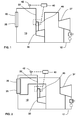
- Fig. 1 shows an exemplary steam Rankine cycle solar plant 10 that compromises a steam generator 20 for generating steam, a multi-stage turbine 30 having a first stage and an intermediate stage downstream of the first stage and a feed line 32 therebetween fluidly connecting the steam generator 29 to the turbine 30.
- a second turbine 37, downstream of the turbine 30 is feed from the exhaust of the turbine 30.
- Each stage of a multi-stage turbine 30 is defined as an adjacent pair of stationary vanes and rotating blades rows wherein the first stage is at the inlet end of the turbine, the last stage is at the outlet end of the turbine, and intermediate stages are located between the first and last stage.
- An exemplary embodiment shown in both Figs 1 includes an overload valve 45 located in the feed line 32 to the turbine 30.
- the overload valve 45 which may comprise a one or more valves, is configured and arranged to divert a portion of steam from the steam generator 20 directly into an intermediate stage of the turbine 30 downstream of the first stage into and but upstream of the last stage. In this way, at least a portion of the steam from the steam generator 20 bypasses the first stage of the turbine 30.
- An exemplary embodiment shown in both Figs 1 includes a sensor 42 located between the outlet of the solar energy concentrator 25 and the inlet of the turbine 30.
- the sensor 42 is configured to measure the pressure of the feed stream to the turbine 30, that is, the pressure in the feed line 32.
- a controller 40 in measurement communication with the sensor 42 uses an algorithm to interpret the pressure measurement from the sensor 42 and generate an output signal which is transmited to the overload valve 45.
- the algorithm is configured to open the overload valve 45 above a critical pressure thus limiting the pressure in the first stage of the turbine 30.
- the overload valve 45 and controller 40 are applied to a solar Rankine cycle 12 with a reheat turbine 37.
- the overload valve 45 and controller 40 are applied to a solar plant 10 where the steam generator 20 is a standalone boiler whose energy input is provided via a heat transfer medium cycle 14 whose thermal energy source includes at least a solar energy concentrator 25.
- the method includes the steps of providing a steam Rankine cycle 12 with a multistage turbine 30 and providing a steam generator 20 who derives at least a portion of its thermal energy from a solar energy concentrator 25. Steam generated from the solar energy concentrator 25 is fed to the turbine 30 either directly in the case where the solar plant 10 comprises only a steam Rankine cycle 12 as shown in Fig. 1 or indirectly when the solar plant 10 comprises an additional heat transfer medium cycle 14 as shown in Fig. 3 .
- the feedline 32 is provided with an overload valve 45, which is capable of splitting feed to the turbine 30 and directing it to the first stage and an intermediate stage of the turbine 30 simultaneously.
- Pressure in the feed line 32 is then measured and provided to a controller 40.
- the controller 40 then uses an algorithm to provide the overload valve 45 with a control signal.
- the controller 40 and its algorithm is such that the proportion of steam first directly to the intermediate stage, that is bypassing the first stage, is varied based on the measured pressure so by limiting the maximum steam pressure at the first stage of the turbine 30. In an exemplary embodiment this is achieved by the overload valve 45 directs all steam feed to the first stage of the turbine 30 below a predetermined pressure and at least some steam feed to the directly to the intermediate stage above a predetermined pressure.
- Another exemplary method additionally provides to a heat transfer medium cycle 14 to the solar plant 10 wherein the steam generator 20 is a heat exchanger that exchanges solar thermal energy between the heat transfer medium cycle 14 and the steam Rankine cycle 12.
Landscapes
- Engineering & Computer Science (AREA)
- Chemical & Material Sciences (AREA)
- Combustion & Propulsion (AREA)
- Mechanical Engineering (AREA)
- General Engineering & Computer Science (AREA)
- Life Sciences & Earth Sciences (AREA)
- Sustainable Development (AREA)
- Sustainable Energy (AREA)
- Engine Equipment That Uses Special Cycles (AREA)
- Control Of Turbines (AREA)
Abstract
Description
- The present disclosure relates generally to steam Rankine cycle solar plants and more specifically to the optimisation of the performance of the turbine within the steam cycle of such solar plants.
- In its most basic form, a solar thermal power plant consists of solar concentrators with mirrors that concentrate the solar radiation to one or more receivers where it is converted to high temperature heat energy. A common configuration of solar thermal power plant is based on conventional Rankine-cycle power generation equipment. Generally, solar thermal applications that are based on the steam Rankine cycle typically fall into two general capture technology categories: linear focussing technology such as parabolic troughs and linear Fresnel concentrators; and point focusing concentrators, such as solar power towers.
- A parabolic trough is a type of concentrator that is constructed as a long parabolic mirror. At the focal point of the mirror is a Dewar tube through which heat transfer medium is passed and heated.
- Linear Fresnel concentrators are similar to parabolic collects in that they focus solar energy along a line. However, they differ in that the mirror comprises horizontally mounted flat mirror stripes that collectively or individually track the sun.
- A solar power tower, also known as 'central tower' power plants or 'heliostat' power plants or simply power towers, is a type of solar furnace using a tower to receive the focused sunlight. The solar power tower typically uses an array of flat, movable mirrors (heliostats) to focus the sun's rays upon a collecting tower. In a steam Rankine cycle solar plant, steam is generated from the concentrated energy at the top of the tower either directly via a solar boiler located in the tower or else via a heat transfer medium chosen for its high heat capacity. By having a high heat capacity the heat transfer medium may suitably be used for the secondary purpose of storing energy during periods of low solar intensity for later use in the thermal cycle. Examples of suitable heat transfer medium include liquid sodium and molten sale (40% potassium nitrate, 60% sodium nitrate).
- One of the characteristic of solar supply is its variable nature. Not only do solar plants need to cope with day/night variations and seasonal variations but also other factors that block or dissipate solar radiation, such as clouds, atmospheric dust and pollution. The demands on the systems are therefore very high which means that the equipment must be able to operated across a wide range of operating conditions far greater than that experience by conventional systems.
- Accordingly, the steam generator, which may either be a superheater or a reheater, can produce a correspondingly large variation in steam quantity as well as steam temperature. Not only must the steam turbine of the plant be designed to cope with relatively rare peak conditions, but the same must be done for other auxiliary equipment include the steam generator, the live-steam lines and other live-steam path components. This means, while the design is typically optimised for the unusual "100% load case" it typically operates, due to oversizing, with lower efficiency at "average conditions".
- One solution is to provide a steam turbine optimised for "average conditions" and reduce the solar collection capacity during periods of peak solar activity by, for example, defocusing the heliostatic mirrors of a solar power tower or not tracking the sun with parabolic mirrors of trough plants. This leads to a lost of potential energy generation.
- Another alternative, in particularly for solar power towers that utilise heat transfer medium loops, is to divert some of the heated heat transfer medium to storage during insolation peaks for later use during low solar thermal intensity, for example, in the evening or at night. This requires a large storage system.
- A further alternative is to provide multiple steam turbines wherein the turbines are configured so that the number of steam turbines placed in service is based on the solar load. This adds both complexity and cost to the installation.
- A steam Rankine cycle solar plant is disclosed that enables a multistage turbine of the solar plant to be optimisation for efficiency at average conditions while still having peaking capacity.
- Embodiments attempt to address this problem by means of the subject matters of the independent claims. Advantageous embodiments are given in the dependent claims.
- According to an aspect of an exemplary embodiment, there is provided a steam Rankine cycle solar plant comprising a steam generator for generating steam, a feed line connected to the steam generator and a multi-stage turbine connected to the steam generator by the feed line wherein the turbine has a first stage and an intermediate stage downstream of the first stage. An overload valve, which is located in the feed line, is configure and arranged to limit the steam pressure of the first stage by directing at least a portion of the steam into the intermediate stage. In this way, a portion of steam can bypass the first stage, thus providing the turbine with peaking capacity.
- In another aspect, the plant further comprises a sensor configured and arranged to measure pressure in the feed line to the turbine. In addition, the plant also comprises a controller in measurement communication with the sensor and in control communication with the overload valve. The controller is configured to adjust the overload valve based on the measurement of the sensor.
- Another aspect includes a solar plant comprising both a heat transfer medium cycle and a steam Rankine cycle. The steam generator is configured and arranged in both cycles to transfer heat from the heat transfer medium cycle to the steam Rankine cycle.
- In another aspect, a solar plant includes a solar thermal energy storage means configured and arranged to store solar thermal energy from the heat transfer medium cycle for later use in the steam generator.
- Another aspect provides a method for controlling a steam Rankine cycle solar steam plant. The method includes the steps of:
- ● providing a steam Rankine cycle with a multistage turbine
- ● feeding steam to the turbine;
- ● measuring pressure in a feed line to the turbine; and
- ● varying the proportion of steam fed directly to an intermediate stage of the turbine based on the measured pressure.
- In an aspect, the measurement step comprises measuring steam in the steam Rankine cycle as it is fed to the turbine.
- In another aspect, the method comprises providing the plant with a heat transfer medium cycle and transferring solar thermal energy from the heat transfer medium cycle to the Steam Rankine cycle by means of a steam generator.
- It is a further object of the invention to overcome or at least ameliorate the disadvantages and shortcomings of the prior art or provide a useful alternative.
- Other aspects and advantages of the present disclosure will become apparent from the following description, taken in connection with the accompanying drawings, which, by way of example, illustrate exemplary embodiments of the present invention.
- By way of example, an embodiment of the present disclosure is described more fully hereinafter with reference to the accompanying drawings, in which:
-
Figure 1 is a schematic view of an exemplary steam Rankine cycle solar plant with a control system according to an exemplary embodiment of the disclosure; and -
Figure 2 is a schematic view of an exemplary steam Rankine cycle solar plant ofFig. 1 with a reheat turbine; and -
Figure 3 is a schematic view of the exemplary steam Rankine cycle solar plant ofFig. 1 with a heat transfer medium cycle. - Exemplary embodiments of the present disclosure are now described with reference to the drawings, wherein like reference numerals are used to refer to like elements throughout. In the following description, for purposes of explanation, numerous specific details are set forth to provide a thorough understanding of the disclosure. However, the present disclosure may be practiced without these specific details, and is not limited to the exemplary embodiment disclosed herein.
- Throughout this specification, in relation to various exemplary embodiments the meaning of the
term steam generator 20 is to encompass a boiler, superheater and reheater or any combination thereof. -
Fig. 1 shows an exemplary steam Rankine cyclesolar plant 10 that compromises asteam generator 20 for generating steam, amulti-stage turbine 30 having a first stage and an intermediate stage downstream of the first stage and afeed line 32 therebetween fluidly connecting the steam generator 29 to theturbine 30. Optionally, asecond turbine 37, downstream of theturbine 30 is feed from the exhaust of theturbine 30. - Each stage of a
multi-stage turbine 30 is defined as an adjacent pair of stationary vanes and rotating blades rows wherein the first stage is at the inlet end of the turbine, the last stage is at the outlet end of the turbine, and intermediate stages are located between the first and last stage. - An exemplary embodiment shown in both
Figs 1 includes anoverload valve 45 located in thefeed line 32 to theturbine 30. Theoverload valve 45, which may comprise a one or more valves, is configured and arranged to divert a portion of steam from thesteam generator 20 directly into an intermediate stage of theturbine 30 downstream of the first stage into and but upstream of the last stage. In this way, at least a portion of the steam from thesteam generator 20 bypasses the first stage of theturbine 30. - An exemplary embodiment shown in both
Figs 1 includes asensor 42 located between the outlet of thesolar energy concentrator 25 and the inlet of theturbine 30. Thesensor 42 is configured to measure the pressure of the feed stream to theturbine 30, that is, the pressure in thefeed line 32. Acontroller 40, in measurement communication with thesensor 42 uses an algorithm to interpret the pressure measurement from thesensor 42 and generate an output signal which is transmited to theoverload valve 45. The algorithm is configured to open theoverload valve 45 above a critical pressure thus limiting the pressure in the first stage of theturbine 30. - In an exemplary embodiment shown in
Fig. 2 theoverload valve 45 andcontroller 40 are applied to asolar Rankine cycle 12 with areheat turbine 37. - In an exemplary embodiment shown in
Fig. 3 , theoverload valve 45 andcontroller 40 are applied to asolar plant 10 where thesteam generator 20 is a standalone boiler whose energy input is provided via a heattransfer medium cycle 14 whose thermal energy source includes at least asolar energy concentrator 25. - Further exemplary embodiments relate to methods of controlling a steam Rankine cycle solar plant. In one exemplary embodiment, the method includes the steps of providing a
steam Rankine cycle 12 with amultistage turbine 30 and providing asteam generator 20 who derives at least a portion of its thermal energy from asolar energy concentrator 25. Steam generated from thesolar energy concentrator 25 is fed to theturbine 30 either directly in the case where thesolar plant 10 comprises only asteam Rankine cycle 12 as shown inFig. 1 or indirectly when thesolar plant 10 comprises an additional heattransfer medium cycle 14 as shown inFig. 3 . In addition, thefeedline 32 is provided with anoverload valve 45, which is capable of splitting feed to theturbine 30 and directing it to the first stage and an intermediate stage of theturbine 30 simultaneously. - Pressure in the
feed line 32 is then measured and provided to acontroller 40. Thecontroller 40 then uses an algorithm to provide theoverload valve 45 with a control signal. Thecontroller 40 and its algorithm is such that the proportion of steam first directly to the intermediate stage, that is bypassing the first stage, is varied based on the measured pressure so by limiting the maximum steam pressure at the first stage of theturbine 30. In an exemplary embodiment this is achieved by theoverload valve 45 directs all steam feed to the first stage of theturbine 30 below a predetermined pressure and at least some steam feed to the directly to the intermediate stage above a predetermined pressure. - Another exemplary method additionally provides to a heat
transfer medium cycle 14 to thesolar plant 10 wherein thesteam generator 20 is a heat exchanger that exchanges solar thermal energy between the heattransfer medium cycle 14 and thesteam Rankine cycle 12. - Although the disclosure has been herein shown and described in what is conceived to be the most practical exemplary embodiment, it will be appreciated by those skilled in the art that the present disclosure can be embodied in other specific forms. The presently disclosed embodiments are therefore considered in all respects to be illustrative and not restricted. The scope of the disclosure is indicated by the appended claims rather that the foregoing description and all changes that come within the meaning and range and equivalences thereof are intended to be embraced therein.
-
- 10
- Steam Rankine cycle solar plant
- 12
- Steam Rankine cycle
- 14
- Heat transfer medium cycle
- 20
- Steam generator
- 25
- Solar energy concentrator
- 30
- Multistage turbine
- 32
- Feed line
- 37
- Reheat turbine
- 40
- Controller
- 42
- Sensor
- 45
- Overload valve
Claims (6)
- A Steam Rankine cycle solar plant (10) comprising:a steam generator (20) for generating steam from solar thermal energy;a feed line (32) connected to the steam generator (20); anda multi-stage turbine (30), with a first stage and an intermediate stage downstream of the first stage, connected to the steam generator (20) by the feed line (32),
characterised by an overload valve (45), located in the feed line (32), configure and arranged to limit the steam pressure of the first stage by directing at least a portion of the steam into the intermediate stage. - The solar plant (10) of claim 1 further comprising:a sensor (42), in the feed line (32), configured and arranged to measure pressure; anda controller (40) in measurement communication with the sensor (42) and in control communication with the overload valve (45),
wherein the controller (40) is configured to adjust the overload valve (45) based on the measurement of the sensor (42). - The solar plant (10) of claims 1 or 2 comprising both a heat transfer medium cycle (14) and a steam Rankine cycle (12),
wherein the steam generator (20) is configured and arranged in both cycles (12,14) to transfer solar thermal energy from the heat transfer medium cycle (14) to the Steam Rankine cycle (12). - A method for controlling a Steam Rankine cycle solar plant (10) comprising the steps of:providing a steam Rankine cycle (12) with a multistage turbine (30);measuring pressure in a feed line (32) to the turbine (30); andvarying the proportion of steam fed directly to an intermediate stage of the turbine (30) based on the measured pressure.
- The method of claim 4 wherein steam is fed directly to an intermediate stage of the turbine (30) only after a predetermined measured pressure is exceeded.
- The method of claim 4 or 5 comprising:providing the plant with a heat transfer medium cycle (14); andtransferring solar thermal energy from the heat transfer medium cycle (14) to the Steam Rankine cycle (12) by means of a steam generator (20).
Priority Applications (4)
| Application Number | Priority Date | Filing Date | Title |
|---|---|---|---|
| EP12169280.0A EP2667027A1 (en) | 2012-05-24 | 2012-05-24 | Steam rankine cycle solar plant and method for operating such plants |
| US13/893,379 US20130312410A1 (en) | 2012-05-24 | 2013-05-14 | Steam rankine cycle solar plant and method for operating such plants |
| CN2013101975042A CN103423111A (en) | 2012-05-24 | 2013-05-24 | Steam Rankine cycle solar plant and method for operating such plants |
| JP2013109744A JP2013245683A (en) | 2012-05-24 | 2013-05-24 | Steam rankine cycle solar plant and method for operating the plant |
Applications Claiming Priority (1)
| Application Number | Priority Date | Filing Date | Title |
|---|---|---|---|
| EP12169280.0A EP2667027A1 (en) | 2012-05-24 | 2012-05-24 | Steam rankine cycle solar plant and method for operating such plants |
Publications (1)
| Publication Number | Publication Date |
|---|---|
| EP2667027A1 true EP2667027A1 (en) | 2013-11-27 |
Family
ID=46172700
Family Applications (1)
| Application Number | Title | Priority Date | Filing Date |
|---|---|---|---|
| EP12169280.0A Withdrawn EP2667027A1 (en) | 2012-05-24 | 2012-05-24 | Steam rankine cycle solar plant and method for operating such plants |
Country Status (4)
| Country | Link |
|---|---|
| US (1) | US20130312410A1 (en) |
| EP (1) | EP2667027A1 (en) |
| JP (1) | JP2013245683A (en) |
| CN (1) | CN103423111A (en) |
Cited By (3)
| Publication number | Priority date | Publication date | Assignee | Title |
|---|---|---|---|---|
| EP2918793A1 (en) * | 2014-03-13 | 2015-09-16 | Siemens Aktiengesellschaft | Control concept for district heating decoupling in a steam power plant |
| EP3128135A1 (en) * | 2015-08-06 | 2017-02-08 | Siemens Aktiengesellschaft | Turbine design in overload inlet area |
| EP3301267A1 (en) * | 2016-09-29 | 2018-04-04 | Siemens Aktiengesellschaft | Method and device for operating a turbo set |
Families Citing this family (5)
| Publication number | Priority date | Publication date | Assignee | Title |
|---|---|---|---|---|
| EP2930422B1 (en) * | 2014-04-08 | 2016-06-15 | Siemens Aktiengesellschaft | Method to operate a steam turbine, steam turbine and concentrated solar power plant |
| EP3128136A1 (en) * | 2015-08-07 | 2017-02-08 | Siemens Aktiengesellschaft | Overload feed into a steam turbine |
| EP3296506A1 (en) * | 2016-09-20 | 2018-03-21 | Siemens Aktiengesellschaft | Assembly for feed of an additional mass flow into a main mass flow |
| CN107989662B (en) * | 2016-10-26 | 2020-06-09 | 上海上电漕泾发电有限公司 | Overflow opening control method for steam turbine steam supplementing valve |
| JP7144334B2 (en) * | 2019-01-30 | 2022-09-29 | 三菱重工コンプレッサ株式会社 | steam turbine system |
Citations (4)
| Publication number | Priority date | Publication date | Assignee | Title |
|---|---|---|---|---|
| US4593527A (en) * | 1984-01-13 | 1986-06-10 | Kabushiki Kaisha Toshiba | Power plant |
| DE10042317A1 (en) * | 2000-08-29 | 2002-03-14 | Alstom Power Nv | Steam turbine for combined cycle power plant, has quick acting valves in combination with regulating valves, provided in both fresh steam and bypass paths |
| EP1632650A1 (en) * | 2004-09-01 | 2006-03-08 | Siemens Aktiengesellschaft | Steam turbine |
| EP2060752A1 (en) * | 2007-02-20 | 2009-05-20 | Mitsubishi Heavy Industries, Ltd. | Steam system, and its control system and control method |
Family Cites Families (3)
| Publication number | Priority date | Publication date | Assignee | Title |
|---|---|---|---|---|
| CA2750004A1 (en) * | 2009-01-19 | 2010-07-22 | Yeda Research And Development Co. Ltd. | Solar combined cycle power systems |
| ES2323355B2 (en) * | 2009-04-16 | 2011-01-04 | Universidad Politecnica De Madrid | METHOD FOR INCREASING THE NET ELECTRICAL POWER OF THERMOSOLAR POWER STATIONS. |
| CN101825072A (en) * | 2010-04-16 | 2010-09-08 | 华中科技大学 | Trough-dish combined solar thermal power generation system with fixed focus |
-
2012
- 2012-05-24 EP EP12169280.0A patent/EP2667027A1/en not_active Withdrawn
-
2013
- 2013-05-14 US US13/893,379 patent/US20130312410A1/en not_active Abandoned
- 2013-05-24 CN CN2013101975042A patent/CN103423111A/en active Pending
- 2013-05-24 JP JP2013109744A patent/JP2013245683A/en not_active Withdrawn
Patent Citations (4)
| Publication number | Priority date | Publication date | Assignee | Title |
|---|---|---|---|---|
| US4593527A (en) * | 1984-01-13 | 1986-06-10 | Kabushiki Kaisha Toshiba | Power plant |
| DE10042317A1 (en) * | 2000-08-29 | 2002-03-14 | Alstom Power Nv | Steam turbine for combined cycle power plant, has quick acting valves in combination with regulating valves, provided in both fresh steam and bypass paths |
| EP1632650A1 (en) * | 2004-09-01 | 2006-03-08 | Siemens Aktiengesellschaft | Steam turbine |
| EP2060752A1 (en) * | 2007-02-20 | 2009-05-20 | Mitsubishi Heavy Industries, Ltd. | Steam system, and its control system and control method |
Cited By (8)
| Publication number | Priority date | Publication date | Assignee | Title |
|---|---|---|---|---|
| EP2918793A1 (en) * | 2014-03-13 | 2015-09-16 | Siemens Aktiengesellschaft | Control concept for district heating decoupling in a steam power plant |
| WO2015135792A1 (en) * | 2014-03-13 | 2015-09-17 | Siemens Aktiengesellschaft | Control concept for district heating extraction in a steam power plant |
| EP3128135A1 (en) * | 2015-08-06 | 2017-02-08 | Siemens Aktiengesellschaft | Turbine design in overload inlet area |
| WO2017021067A1 (en) * | 2015-08-06 | 2017-02-09 | Siemens Aktiengesellschaft | Turbine design in the overload inflow region |
| EP3301267A1 (en) * | 2016-09-29 | 2018-04-04 | Siemens Aktiengesellschaft | Method and device for operating a turbo set |
| WO2018059864A1 (en) * | 2016-09-29 | 2018-04-05 | Siemens Aktiengesellschaft | Method for operating a turbogenerator |
| CN109790761A (en) * | 2016-09-29 | 2019-05-21 | 西门子股份公司 | Method for running turbine set |
| CN109790761B (en) * | 2016-09-29 | 2020-05-19 | 西门子股份公司 | Method for operating a turbomachine |
Also Published As
| Publication number | Publication date |
|---|---|
| US20130312410A1 (en) | 2013-11-28 |
| JP2013245683A (en) | 2013-12-09 |
| CN103423111A (en) | 2013-12-04 |
Similar Documents
| Publication | Publication Date | Title |
|---|---|---|
| US20130312410A1 (en) | Steam rankine cycle solar plant and method for operating such plants | |
| US8039984B2 (en) | System for converting solar radiation into electricity | |
| US20120240577A1 (en) | Thermal generation systems | |
| US10690121B2 (en) | Integrated cascading cycle solar thermal plants | |
| US20130111902A1 (en) | Solar power system and method of operating a solar power system | |
| Antonelli et al. | Electrical production of a small size Concentrated Solar Power plant with compound parabolic collectors | |
| Reyes-Belmonte et al. | Annual performance of subcritical Rankine cycle coupled to an innovative particle receiver solar power plant | |
| Ait Lahoussine Ouali et al. | Performance of parabolic through solar power plant under weather conditions of the Oujda city in Morocco | |
| de Araújo Coutinho et al. | Thermoeconomic analysis and optimization of a hybrid solar-thermal power plant using a genetic algorithm | |
| Wang et al. | Thermoeconomic assessment of a spectral-splitting hybrid PVT system in dairy farms for combined heat and power | |
| Pitz-Paal | Concentrating solar power systems | |
| EP2667028A1 (en) | A steam Rankine cycle solar plant and method for operating such plants | |
| WO2013065492A1 (en) | Solar heat turbine electricity generation device and control method therefor | |
| Romero et al. | Terrestrial solar thermal power plants: on the verge of commercialization | |
| AU2016349191B2 (en) | Solar heat collection system and operation method thereof | |
| Poullikkas et al. | Optimum sizing of steam turbines for concentrated solar power plants | |
| Schenk et al. | Energetic comparison of linear Fresnel and parabolic trough collector systems | |
| Pitz-Paal | Concept and status of Concentrating Solar Power systems | |
| JP2017101578A (en) | Composite turbine system and power generation method thereof | |
| Suyanto et al. | A review of linear Fresnel reflector technology for heating sulphur liquid in nickel processing industry | |
| Bockamp et al. | Solar thermal power generation | |
| Sanz-Bermejo et al. | Performance analysis of direct steam generation-central receiver systems | |
| Pitz‐Paal | How the sun gets into the power plant | |
| Zhang et al. | Start-Up Operation Strategy Optimization of the Solar Field for a Parabolic Trough Concentrated Solar Power Plant | |
| Alshahrani et al. | Development and Investigation of a Solar-Biogas Hybrid Brayton Cycle for 100 kW Power Generation |
Legal Events
| Date | Code | Title | Description |
|---|---|---|---|
| PUAI | Public reference made under article 153(3) epc to a published international application that has entered the european phase |
Free format text: ORIGINAL CODE: 0009012 |
|
| AK | Designated contracting states |
Kind code of ref document: A1 Designated state(s): AL AT BE BG CH CY CZ DE DK EE ES FI FR GB GR HR HU IE IS IT LI LT LU LV MC MK MT NL NO PL PT RO RS SE SI SK SM TR |
|
| AX | Request for extension of the european patent |
Extension state: BA ME |
|
| 17P | Request for examination filed |
Effective date: 20131105 |
|
| RBV | Designated contracting states (corrected) |
Designated state(s): AL AT BE BG CH CY CZ DE DK EE ES FI FR GB GR HR HU IE IS IT LI LT LU LV MC MK MT NL NO PL PT RO RS SE SI SK SM TR |
|
| STAA | Information on the status of an ep patent application or granted ep patent |
Free format text: STATUS: THE APPLICATION IS DEEMED TO BE WITHDRAWN |
|
| 18D | Application deemed to be withdrawn |
Effective date: 20140528 |