EP2666980A1 - Variable valve timing control apparatus - Google Patents
Variable valve timing control apparatus Download PDFInfo
- Publication number
- EP2666980A1 EP2666980A1 EP13168991.1A EP13168991A EP2666980A1 EP 2666980 A1 EP2666980 A1 EP 2666980A1 EP 13168991 A EP13168991 A EP 13168991A EP 2666980 A1 EP2666980 A1 EP 2666980A1
- Authority
- EP
- European Patent Office
- Prior art keywords
- oil passage
- outside space
- seal ring
- retarded angle
- groove
- Prior art date
- Legal status (The legal status is an assumption and is not a legal conclusion. Google has not performed a legal analysis and makes no representation as to the accuracy of the status listed.)
- Granted
Links
- 239000012530 fluid Substances 0.000 claims abstract description 75
- 241000239290 Araneae Species 0.000 claims abstract description 32
- 230000007246 mechanism Effects 0.000 claims abstract description 30
- 238000000638 solvent extraction Methods 0.000 claims abstract description 5
- 238000004891 communication Methods 0.000 claims description 38
- 238000002485 combustion reaction Methods 0.000 claims description 28
- 238000009825 accumulation Methods 0.000 description 5
- 230000005540 biological transmission Effects 0.000 description 3
- 230000006835 compression Effects 0.000 description 3
- 238000007906 compression Methods 0.000 description 3
- 238000003780 insertion Methods 0.000 description 3
- 230000037431 insertion Effects 0.000 description 3
- 239000007858 starting material Substances 0.000 description 3
- YCKRFDGAMUMZLT-UHFFFAOYSA-N Fluorine atom Chemical compound [F] YCKRFDGAMUMZLT-UHFFFAOYSA-N 0.000 description 2
- 230000008859 change Effects 0.000 description 2
- 230000007423 decrease Effects 0.000 description 2
- 229910052731 fluorine Inorganic materials 0.000 description 2
- 239000011737 fluorine Substances 0.000 description 2
- 239000000446 fuel Substances 0.000 description 2
- 239000000463 material Substances 0.000 description 2
- 238000000034 method Methods 0.000 description 2
- 230000007935 neutral effect Effects 0.000 description 2
- 238000005192 partition Methods 0.000 description 2
- 238000005086 pumping Methods 0.000 description 2
- 230000001133 acceleration Effects 0.000 description 1
- 230000004913 activation Effects 0.000 description 1
- 230000000903 blocking effect Effects 0.000 description 1
- 239000002826 coolant Substances 0.000 description 1
- 239000011347 resin Substances 0.000 description 1
- 229920005989 resin Polymers 0.000 description 1
- 230000004044 response Effects 0.000 description 1
- 230000004043 responsiveness Effects 0.000 description 1
- 230000000452 restraining effect Effects 0.000 description 1
- 230000007704 transition Effects 0.000 description 1
- XLYOFNOQVPJJNP-UHFFFAOYSA-N water Substances O XLYOFNOQVPJJNP-UHFFFAOYSA-N 0.000 description 1
Images


Classifications
-
- F—MECHANICAL ENGINEERING; LIGHTING; HEATING; WEAPONS; BLASTING
- F02—COMBUSTION ENGINES; HOT-GAS OR COMBUSTION-PRODUCT ENGINE PLANTS
- F02D—CONTROLLING COMBUSTION ENGINES
- F02D13/00—Controlling the engine output power by varying inlet or exhaust valve operating characteristics, e.g. timing
-
- F—MECHANICAL ENGINEERING; LIGHTING; HEATING; WEAPONS; BLASTING
- F01—MACHINES OR ENGINES IN GENERAL; ENGINE PLANTS IN GENERAL; STEAM ENGINES
- F01L—CYCLICALLY OPERATING VALVES FOR MACHINES OR ENGINES
- F01L1/00—Valve-gear or valve arrangements, e.g. lift-valve gear
- F01L1/34—Valve-gear or valve arrangements, e.g. lift-valve gear characterised by the provision of means for changing the timing of the valves without changing the duration of opening and without affecting the magnitude of the valve lift
- F01L1/344—Valve-gear or valve arrangements, e.g. lift-valve gear characterised by the provision of means for changing the timing of the valves without changing the duration of opening and without affecting the magnitude of the valve lift changing the angular relationship between crankshaft and camshaft, e.g. using helicoidal gear
- F01L1/3442—Valve-gear or valve arrangements, e.g. lift-valve gear characterised by the provision of means for changing the timing of the valves without changing the duration of opening and without affecting the magnitude of the valve lift changing the angular relationship between crankshaft and camshaft, e.g. using helicoidal gear using hydraulic chambers with variable volume to transmit the rotating force
-
- F—MECHANICAL ENGINEERING; LIGHTING; HEATING; WEAPONS; BLASTING
- F01—MACHINES OR ENGINES IN GENERAL; ENGINE PLANTS IN GENERAL; STEAM ENGINES
- F01L—CYCLICALLY OPERATING VALVES FOR MACHINES OR ENGINES
- F01L1/00—Valve-gear or valve arrangements, e.g. lift-valve gear
- F01L1/34—Valve-gear or valve arrangements, e.g. lift-valve gear characterised by the provision of means for changing the timing of the valves without changing the duration of opening and without affecting the magnitude of the valve lift
- F01L1/344—Valve-gear or valve arrangements, e.g. lift-valve gear characterised by the provision of means for changing the timing of the valves without changing the duration of opening and without affecting the magnitude of the valve lift changing the angular relationship between crankshaft and camshaft, e.g. using helicoidal gear
- F01L1/3442—Valve-gear or valve arrangements, e.g. lift-valve gear characterised by the provision of means for changing the timing of the valves without changing the duration of opening and without affecting the magnitude of the valve lift changing the angular relationship between crankshaft and camshaft, e.g. using helicoidal gear using hydraulic chambers with variable volume to transmit the rotating force
- F01L2001/3445—Details relating to the hydraulic means for changing the angular relationship
- F01L2001/34479—Sealing of phaser devices
Definitions
- This disclosure generally relates to a variable valve timing control apparatus.
- a known variable valve timing control apparatus where a relative rotational phase of a driven-side rotating member rotating integrally with a cam shaft of an internal combustion engine relative to a driving-side rotating member rotating synchronously with a crank shaft of the internal combustion engine is controlled, includes a fluid pressure chamber formed between the driving-side rotating member and the driven-side rotating member, and a partition provided for partitioning or separating the fluid pressure chamber into an advanced angle chamber and a retarded angle chamber.
- switching between supply and discharge of working fluid relative to the advanced angle chamber or the retarded angle chamber is controlled, and thus the relative rotational phase of the driven-side rotating member relative to the driving-side rotating member is controlled.
- a known valve timing changing apparatus (corresponding to the above-described variable valve timing control apparatus) disclosed in Patent reference 1 includes a rotating body (corresponding to the above-described driven-side rotating member) and an outer side rotating body arranged at an outer side (corresponding to the above-described driving-side rotating member) which are arranged coaxially with each other, and two fluid pressure chambers which are supplied with working fluid via respective two fluid pressure passages.
- the valve timing changing apparatus changes a relative rotational position of the rotating body and the outer side rotating body relative to each other on the basis of fluid pressure of the two fluid pressure chambers, and thereby changing a valve timing of a intake valve or an exhaust valve of an internal combustion engine.
- the rotating body is arranged at an outer periphery of a substantially column-shaped body axis to be coaxially with the body axis.
- the two fluid pressure passages are connected via respective inner passages of the body axis to respective annular passages formed between the body axis and the rotating body.
- seal rings partitioning the respective annular passages of the two fluid pressure passages are disposed between the axis body and the rotating body, and ring grooves each of which is recessed to have a substantially rectangular cross section are formed at an outer circumferential surface of the body axis or an inner circumferential surface of the rotating body.
- the seal rings are arranged at the respective ring grooves in a manner that each of the seal rings enters the corresponding ring groove.
- variable valve timing control apparatuses before a start-up of the internal combustion engine, the relative rotational phase of the rotating body and the outer side rotating body relative to each other is fixed at an intermediate position between a most retarded angle and a most advanced angle before a start-up of the internal combustion engine, and the relative rotational phase is controlled to move to the most retarded angle-side or the most advanced angle-side after the start-up of the internal combustion engine.
- the intake valve or the exhaust valve of the internal combustion engine of which relative rotational phase is controlled by the variable valve timing control apparatus is pressed downwardly (or pressed upwardly) against a valve spring, and therefore an intake timing or an exhaust timing may possibly delay relative to a desired or intended timing.
- an operation of the internal combustion engine may deviate from a desired or intended operation.
- the relative rotational phase be controlled to move quickly from the intermediate position to the most retarded angle-side or to the most advanced angle-side.
- variable valve timing control apparatus is configured so that the supply and the discharge of the working fluid are conducted, and that a pump provided at a supply path of the working fluid of the variable valve timing control apparatus pumps up the working fluid from an oil pan. Accordingly, depending on a flow path resistance of the supply path, the working fluid may not be supplied to the variable valve timing control apparatus immediately after the pump starts.
- a discharge path of the working fluid of the variable valve timing control apparatus is configured so that the working fluid returns to the oil pan freely without intervention of, for example, the pump.
- the flow path resistance at the discharge path is set to be relatively low, and thus the working fluid is discharged easily (that is, a drainage performance is high).
- the working fluid may not be supplied smoothly to one of the advanced angle chamber and the retarded angle chamber in order to move the relative rotational phase from the intermediate position to the most retarded angle-side or to the most advanced angle-side.
- it is difficult to move the relative rotational phase of the rotating body relative to the outer side rotating body to the desired or intended relative rotational phase and therefore it may take time for transition to the desired rotational phase to take place. Consequently, the operation of the internal combustion engine may deviate from the desired or intended operation.
- variable valve timing control apparatus which is configured to operate stably even at start-up of an internal combustion engine.
- variable valve timing control apparatus includes a driving-side rotating member rotating synchronously with a crank shaft of an internal combustion engine, a driven-side rotating member rotating integrally with a cam shaft of the internal combustion engine and being rotatable relative to the driving-side rotating member, a control valve operating for switching supply and discharge of a working fluid in a selective manner relative to an advanced angle chamber and a retarded angle chamber which are provided between the driving-side rotating member and the driven-side rotating member, an advanced angle-side oil passage providing fluid communication between the control valve and the advanced angle chamber, a retarded angle-side oil passage providing fluid communication between the control valve and the retarded angle chamber, a spider arranged coaxially with the cam shaft and provided with a first oil passage and a second oil passage which is different from the first oil passage, a part of the advanced angle-side oil passage functioning as the first oil passage, a part of the retarded angle-side oil passage functioning as the second oil passage, a seal mechanism partitioning between at least one of the first
- the seal mechanism includes an annular groove provided at at least one of an outer circumferential surface of the spider and an inner circumferential surface of the driven-side rotating member, the seal mechanism includes a seal ring at least part of which is fitted in the annular groove, and the seal ring includes a radial direction groove provided at a first end surface of the seal ring and extending in a radial direction of the seal ring, the first end surface faces in an opposite direction to the outside space.
- the atmospheric air may be introduced, via the radial direction groove provided at the seal ring, to one of the first oil passage and to the second oil passage of which air pressure is lower than the air pressure of the outside space.
- the negative pressure state of the first oil passage and the second oil passage is solved or eliminated quickly. Consequently, the variable valve timing control apparatus is operated stably even at the start-up of the internal combustion engine.
- the seal mechanism includes the annular groove provided at at least one of the outer circumferential surface of the spider and the inner circumferential surface of the driven-side rotating member, the seal mechanism includes the seal ring at least part of which is fitted in the annular groove, the spider includes a wall portion facing in a direction of the outside space, and the wall portion is provided with the radial direction groove extending in a radial direction of the spider.
- the atmospheric air is introduced to one of the first oil passage and the second oil passage via the radial direction groove provided at the wall portion before the air pressure of the one of the first oil passage and the second oil passage becomes lower than the air pressure of the outside space.
- the negative pressure state of the first oil passage and the second oil passage is solved or eliminated quickly. Consequently, the variable valve timing control apparatus is operated stably even at the start-up of the internal combustion engine.
- the seal ring includes a communication hole providing fluid communication between the second end surface of the seal ring and the first end surface of the seal ring, the second end surface faces in the direction of the outside space and the first end surface faces in the opposite direction to the outside space.
- the atmospheric air is introduced to one of the first oil passage and the second oil passage of which air pressure is lower than the air pressure of the outside space via the communication hole provided at the seal ring.
- the negative pressure state of the first oil passage and the second oil passage is solved or eliminated quickly. Consequently, the variable valve timing control apparatus is operated stably even at the start-up of the internal combustion engine.
- Fig. 1 is a cross-sectional view of a variable valve timing control apparatus according to an embodiment disclosed here;
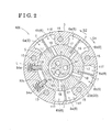
- Fig. 2 is a cross-sectional view taken along line II-II in Fig. 1 ;
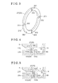
- Fig. 3 is a perspective view of a seal ring provided with a radial direction groove according to the embodiment
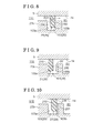
- Fig. 4 is a view illustrating an example where air pressure of a retarded angle control groove is higher than air pressure of an outside space
- Fig. 5 is a view illustrating an example where the air pressure of the retarded angle control groove is lower than the air pressure of the outside space;
- Fig. 6 is a cross-sectional view of a variable valve timing control apparatus according to another embodiment disclosed here;
- Fig. 7 is a view illustrating an example where a seal ring according to the another embodiment is applied.
- Fig. 8 is a view illustrating the example where the seal ring according to the another embodiment is applied.
- Fig. 9 is a view illustrating a radial direction groove according to the another embodiment.
- Fig. 10 is a view illustrating the radial direction groove according to the another embodiment.
- variable valve timing control apparatus 100 is configured to improve responsiveness immediately after an internal combustion engine starts.
- the variable valve timing control apparatus 100 will be explained with reference to the drawings.
- the variable valve timing control apparatus 100 includes an outer rotor 3 (i.e., a driving-side rotating member) and a front plate 4 both of which rotate synchronously with a crank shaft 71 of an engine E (i.e., an internal combustion engine), and a inner rotor 5 (i.e., a driven-side rotating member) which rotates coaxially and integrally with a cam shaft 8 for opening/closing an intake valve 72 of a combustion chamber 73 of the engine E.
- the variable valve timing control apparatus 100 is configured by a combination of the above-described members so that the inner rotor 5 is rotatable about an axis X of the cam shaft 8 relative to the outer rotor 3 and to the front plate 4.
- variable valve timing control apparatus 100 controls an open/close timing of the intake valve 72 by means of a setting of a relative rotational phase (a relative rotation angle) of rotation of the inner rotor 5 and the outer rotor 3 about the axis X relative to each other.
- the inner rotor 5 is integrally mounted on a distal end of the cam shaft 8 that constitutes the rotational shaft of a cam 8a controlling opening/closing of the intake valve 72 of the engine E.
- the inner rotor 5 includes a recessed portion 14 at an inner side in a radial direction of the inner rotor 5.
- a fixing hole 12 is provided at the distal end of the cam shaft 8.
- a bolt 13 is inserted in the fixing hole 12, thereby fixedly fastening the inner rotor 5 to the cam shaft 8.
- the cam shaft 8 is rotatably assembled on a cylinder head of the engine E.
- the engine E is an Atkinson cycle engine and is mounted on a hybrid-type vehicle including a hybrid-type drive mechanism.
- the hybrid-type drive mechanisms include a series type and/or a series-parallel type.
- the intake valve 72 is biased by a valve spring 72a in a closing direction.
- the intake valve 72 is switched by the cam 8a between an open position where the intake valve 72 moves in a press-down direction to be opened, and a close position where the intake valve 72 is closed by a biasing force of the valve spring 72a.
- An electric motor M is connected via a main clutch 74 to the crank shaft 71.
- the engine E including the electric motor M, is managed by an engine management unit 90 configured as an ECU.
- the engine management unit 90 manages, for example, an intake system, a fuel supply system, an ignition spark timing of an ignition plug 75, start-up of the engine by the electric motor M and stop of the engine E.
- the engine management unit 90 includes an engine control portion 91 configured by software and a timing control portion 92 constituted by software.
- the engine control portion 91 performs an automatic start and an automatic stop of the engine E.
- the timing control portion 92 controls an amount of intake air of the engine E by controlling the variable valve timing control apparatus 100.
- the electric motor M functions as a starter motor and as a generator.
- the electric motor M as the starter motor, drives the crank shaft 71 to rotate by means of electric power from a battery in response to an operation of an ignition switch 95, so that the engine E starts.
- the electric motor M as the generator, generates electric power by means of a driving force from the crank shaft 71.
- the electric power generated by the electric motor M is charged in the battery.
- variable valve timing control apparatus 100 At the vehicle provided with the hybrid-type drive mechanism, the automatic start-up and the automatic stop of the engine E take place frequently.
- the variable valve timing control apparatus 100 illustrated in Fig. 1 controls the relative rotation angle to be set at a most retarded angle so that the automatic start-up at the next time is performed with a small load imposed on the electric motor M. Further, at a system stop, the variable valve timing control apparatus 100 controls the relative rotation angle to be set at a lock angle in order to achieve a stable start-up of the engine E at the next time.
- the outer rotor 3 and the inner rotor 5 are arranged to be coaxial with the axis X.
- the inner rotor 5 is fitted inside the outer rotor 3, and the inner rotor 5 and the outer rotor 3 are configured to be sandwiched between the front plate 4 and a rear plate 11.
- the front plate 4 and the rear plate 11 are connected to the outer rotor 3 by means of a connecting bolt 15, for example, by plural connecting bolts 15.
- a timing sprocket 16 is provided at an outer circumference of the rear plate 11.
- the inner rotor 5 and the rear plate 11 are arranged coaxially with each other, and the inner rotor 5 and the cam shaft 8 are securely connected to each other with the bolt 13.
- the crank shaft 71 is driven to rotate, the rotative power is transmitted via the power transmission member 77 to the timing sprocket 16, and therefore the outer rotor 3 is driven to rotate.
- the inner rotor 5 is driven to rotate and the cam shaft 8 rotates.
- the cam 8a provided at the cam shaft 8 presses down the intake valve 72 of the engine E so that the intake valve 72 opens.
- the outer rotor 3 is provided with plural protruding portions 11T each protruding toward the inner side in the radial direction so that a fluid pressure chamber 6 is formed or defined between the adjacent protruding portions 11T in a rotational direction.
- the inner rotor 5 is formed in a cylindrical shape having an outer periphery that is closely in contact with the plural protruding portions 11T.
- the inner rotor 5 includes plural vanes 7 each of which is fitted in the corresponding fluid pressure chamber 6 and each of which partitions the corresponding fluid pressure chamber 6 into two spaces in the rotational direction.
- Each of the fluid pressure chambers 6 is partitioned or divided by the corresponding vane 7 into an advanced angle chamber 6a and a retarded angle chamber 6b in a relative rotational direction (a direction of an arrow S1 and a direction of an arrow S2 in Fig. 2 ).
- the advanced angle chamber 6a and the retarded angle chamber 6b are formed between the inner rotor 5 and the outer rotor 3. Further, the inner rotor 5 is provided with an advanced angle chamber communication hole 17 and a retarded angle chamber communication hole 18.
- the advanced angle chamber communication hole 17 provides fluid communication between the recessed portion 14 formed in a cylindrical configuration and the advanced angle chamber 6a.
- the retarded angle chamber communication hole 18 provides fluid communication between the recessed portion 14 and the retarded angle chamber 6b.
- the advanced angle direction S1 refers to a direction in which the vane 7 is displaced relative to the outer rotor 3, that is, the clockwise direction in Fig. 2
- the retarded angle direction S2 refers to a direction in which the vane 7 is displaced relative to the outer rotor 3, that is, the counterclockwise direction in Fig. 2
- a relationship between the crank shaft 71 and the cam shaft 8 is set so that an intake air compression ratio increases as an amount of change of the relative phase increases when the relative rotational phase changes in the advanced angle direction S1, and so that the intake air compression ratio decreases as the amount of change of the relative phase increases when the relative rotational phase changes in the retarded angle direction S2.
- the relative rotation angle in a state where the vane 7 reaches a movable end (that is, an end in the rotation of the vane 7 about the axis X) in the advanced angle direction S1 is referred to as a most advanced angle
- the relative rotation angle in a state where the vane 7 reaches a movable end (that is, an end in the rotation of the vane 7 about the axis X) at a retarded angle-side is referred to as a most retarded angle.
- the variable valve timing control apparatus 100 is configured so that the relative rotation angle may be set in a control area between the most advanced angle and the most retarded angle.
- the most advanced angle refers to not only the movable end of the vane 7 in the advanced angle direction S1 but also a vicinity thereof.
- the most retarded angle refers to not only the movable end of the vane 7 in the retarded angle direction S2 but also a vicinity thereof.
- the variable valve timing control apparatus 100 includes an intermediate lock mechanism L for restraining or locking the relative rotation angle of the outer rotor 3 and the inner rotor 5 relative to each other at the lock angle between the most advanced angle and the most retarded angle (in the control area).
- the intermediate lock mechanism L includes a pair of lock members 92a, lock springs 94a and a lock groove portion 12L.
- Each of the pair of lock members 92a is configured to protrude and recess relative to the outer rotor 3 in a posture in which each of the lock members 92a is orthogonal to the axis X, so that a protruding end of the lock member 92a comes closer to and away from the axis X.
- Each of the lock springs 94a biases the corresponding lock member 92a in a protruding direction thereof.
- the lock groove portion 12L is provided at the outer periphery of the inner rotor 5 so that the lock members 92a are inserted into and come out of the lock groove portion 12L.
- the relative rotation angle of the outer rotor 3 and the inner rotor 5 relative to each other is locked at the lock angle in a manner that the pair of lock members 92a are engaged in the lock groove portion 12L by insertion at the same time with each other.
- the engine starts up appropriately even when an engine temperature is low.
- the intake air compression ratio that allows the engine E to operate efficiently at a low fuel consumption is set.
- the configuration of the intermediate lock mechanism L is not limited thereto, and the lock member slidably moving in a posture in which the lock member is parallel to the axis X may be provided at the inner rotor 5, and a recessed portion which the lock member engages with and disengages from may be provided at the front plate 4 or the rear plate 11, for example.
- the advanced angle chamber communication hole 17 having the fluid communication with the advanced angle chamber 6a, the retarded angle chamber communication hole 18 having the fluid communication with the retarded angle chamber 6b and an unlocking oil passage 19 having fluid communication with the lock groove portion 12L are provided at the inner rotor 5.
- An advanced angle control groove 82 i.e., a first oil passage
- a retarded angle control groove 83 i.e., a second oil passage
- a lock control groove 84 is provided so as to have fluid communication with the unlocking oil passage 19.
- Each of the advanced angle control groove 82, the retarded angle control groove 83 and the lock control groove 84 is formed in an annular configuration.
- the engine E is provided with the pump P for pumping up oil in an oil pan 80 and for pumping out or transmitting the oil as the working fluid, by means of the driving force of the engine E.
- the variable valve timing control apparatus 100 is provided with a relative rotation angle control valve 124 (i.e., a control valve) which is a solenoid-operated type valve, a lock control valve 125 which is a solenoid-operated type valve, an pressure accumulation control valve 126 which is a solenoid-operated type valve, an accumulator 127 and the engine management unit 90 controlling or managing these three valves (mainly, the control of the timing control portion 92).
- a check valve 128 allowing a flow of the working fluid pumped out from the pump P and blocking a flow of the working oil in a direction of the pump P.
- An oil passage system is established, where the working fluid transmitted from the check valve 128 is branched into and pumped out to a rotation angle control oil passage 129, a lock control oil passage 130 and an oil connection passage 131.
- the rotation angle control oil passage 129 is connected to the relative rotation angle control valve 124
- the lock control oil passage 130 is connected to the lock control valve 125
- the oil connection passage 131 is connected to the pressure accumulation control valve 126.
- the relative rotation angle control valve 124 is connected to the advanced angle control groove 82 and to the retarded angle control groove 83
- the lock control valve 125 is connected to the lock control groove 84.
- the relative rotation angle control valve 124 is configured to be operable at an advanced angle position, a retarded angle position and a neutral position.
- the relative rotation angle control valve 124 supplies the working fluid of the pump P to the advanced angle chamber 6a through an advanced angle-side oil passage 42 and discharges the working fluid in the retarded angle chamber 6b through a retarded angle-side oil passage 43.
- the relative rotation angle control valve 124 supplies the working fluid of the pump P to the retarded angle chamber 6b through the retarded angle-side oil passage 43 and discharges the working fluid in the advanced angle chamber 6a through the advanced angle-side oil passage 42.
- the relative rotation angle control valve 124 does not supply the working fluid either to the advanced angle chamber 6a or to the retarded angle chamber 6b.
- the lock control valve 125 is configured to be operable at an unlock position and a lock position. At the unlock position, the lock control valve 125 supplies the working fluid of the pump P to the lock groove portion 12L via the unlocking oil passage 19, thereby releasing the lock. At the lock position, the lock control valve 125 discharges the working fluid out of the lock groove portion 12L, thereby allowing the lock.
- the pressure accumulation control valve 126 is configured to be operable at an open position at which the working fluid of the pump P is supplied to the accumulator 127 (that is, the supply/discharge is allowed) and a close position at which supply of the working fluid from the pump P to the accumulator 127 is blocked (that is, the supply/discharge is disabled).
- a signal system includes the ignition switch 95 for starting the engine E, a crank shaft sensor 76 configured to measure a rotation angle and a rotation speed of the crank shaft 71 of the engine E and an engine temperature sensor 79 for measuring the temperature of the engine E on the basis of temperature of coolant water of the engine E.
- signals from the ignition switch 95, the crank shaft sensor 76 and the engine temperature sensor 79 are inputted to the engine management unit 90. Further another signal system is established, where control signals are outputted from the engine management unit 90 to the electric motor M, to an ignition circuit for actuating the ignition plug 75 and to a throttle control circuit.
- control signals are outputted to the relative rotation angle control valve 124, to the lock control valve 125 and to the pressure accumulation control valve 126.
- Signals from, for example, an acceleration sensor measuring an operation amount of an accelerator pedal and/or from a running speed sensor are inputted to the engine management unit 90.
- the ignition switch 95 is configured as a switch for starting up a system, that is, an electric system of the vehicle.
- a system activation state is established where electric power is supplied to the electric system and the automatic start and the automatic stop of the engine E are allowed.
- the ignition switch 95 is operated to be OFF, the system stops.
- the ignition switch 95 is operated to be OFF in a case where the engine E is in an operation state, the engine E stops.
- a signal obtained when the ignition switch 95 is turned ON is referred to as a system start-up trigger.
- the ignition switch 95 As the ignition switch 95, a switch that is actuated by a pressing operation is assumed, that is, a first pressing operation functions as an ON operation and the next pressing operation functions as an OFF operation, however, the ignition switch 95 may be a switch that is operated by rotating by use of a key. Alternatively, the ignition switch 95 may be configured so that the ON operation and the OFF operation are performed with switches that are provided separately from each other.
- the electric motor M functions as the starter motor and as the generator as described above, in a case where the battery voltage decreases when the engine E is stopped (that is, in a case where a start condition is fulfilled), an automatic start-up trigger is generated and the engine management unit 90 causes the engine E to be started by a driving of the electric motor M, and causes the battery to be charged. In a case where the battery is charged and thus the battery voltage increases up to a predetermined voltage (that is, in a case where a stop condition is fulfilled), an automatic stop trigger is generated and the engine management unit 90 controls the engine E to stop.
- the relative rotation angle control valve 124 serves as the control valve, and operates for switching supply and discharge of the working fluid in a selective manner relative to the advanced angle chamber 6a and the retarded angle chamber 6b. That is, the relative rotation angle control valve 124 discharges the working fluid from the retarded angle chamber 6b when supplying the working fluid to the advanced angle chamber 6a, and the relative rotation angle control valve 124 discharges the working fluid from the advanced angle chamber 6a when supplying the working fluid to the retarded angle chamber 6b.
- a housing 23 is arranged at a front end of the variable valve timing control apparatus 100 and includes a spider 23b formed in a protruding shape.
- the spider 23b includes a cylindrical configuration that corresponds to a configuration of the recessed portion 14 of the inner rotor 5 and is arranged coaxially with the cam shaft 8.
- the spider 23b is arranged so that a predetermined clearance is provided between an inner circumferential surface of the recessed portion 14 and an outer circumferential surface of the spider 23b.
- fluid communication is provided between the relative rotation angle control valve 124 and the advanced angle chamber 6a by means of the advanced angle-side oil passage 42.
- fluid communication is provided between the relative rotation angle control valve 124 and the retarded angle chamber 6b by means of the retarded angle-side oil passage 43.
- the spider 23b is arranged inside the recessed portion 14 of the inner rotor 5 by insertion so as to be rotatable relative to the inner rotor 5 and the housing 23 is fixed at, for example, a front cover of the engine E.
- the inner rotor 5 is supported by the spider 23b so as to be rotatable relative to the spider 23b.
- the spider 23b is provided with the advanced angle control groove 82 and the retarded angle control groove 83.
- annular grooves 102, 103 and 104 are provided at the outer circumferential surface of the spider 23b.
- the annular grooves 102, 103 and 104 are arranged to be coaxial with the cam shaft 8 in a similar manner to that the spider 23b is coaxially arranged with the cam shaft 8.
- the annular grooves 102, 103 and 104 are arranged on the outer circumferential surface of the spider 23b to be offset from one another in a protruding direction.
- a seal ring 27 is provided at each of the annular grooves 102, 103 and 104.
- the advanced angle control groove 82 is defined by an enclosed space enclosed by the inner circumferential surface of the recessed portion 14, the outer circumferential surface of the spider 23b and the seal ring 27 provided at the annular groove 102, and the advanced angle control groove 82 constitutes a part of the advanced angle-side oil passage 42.
- the retarded angle control groove 83 is defined by an enclosed space enclosed by the inner circumferential surface of the recessed portion 14, the outer circumferential surface of the spider 23b, the seal ring 27 provided at the annular groove 103 and the seal ring 27 provided at the annular groove 104, and the retarded angle control groove 83 constitutes a part of the retarded angle-side oil passage 43.
- the part of the advanced angle-side oil passage 42 functions as the advanced angle control groove 82 and the part of the retarded angle-side oil passage 43 functions as the retarded angle control groove 83.
- the seal ring 27, which is for preventing the working fluid from leaking, is provided at each of the annular grooves 102, 103 and 104 in a manner that at least a part of each of the seal rings 27, for example, a radially inner end portion of the seal ring 27, fits in (that is, accommodated in) the corresponding annular groove 102, 103 or 104, and in a manner that a radially outer end portion of each of the seal ring 27 is in contact with the inner circumferential surface of the recessed portion 14 according to this embodiment.
- the annular groove 103 and the seal ring 27 arranged at the annular groove 103 constitute a seal mechanism 29.
- the retarded angle control groove 83 is partitioned or separated from an outside space 110 by the seal mechanism 29.
- the outside space 110 refers to the space which is at an outer side relative to the outer rotor 3 and the front plate 4, and is under an environment of an atmospheric pressure.
- a lock-side oil passage 47 is provided inside the spider 23b to extend in an extending direction of the spider 23b, that is, in an extending direction of the cam shaft 8.
- One end of the advanced angle-side oil passage 42 is in fluid communication with the relative rotation angle control valve 124 and the other one end thereof opens to the advanced angle control groove 82.
- One end of the retarded angle-side oil passage 43 is in fluid communication with the relative rotation angle control valve 124 and the other one end thereof opens to the retarded angle control groove 83.
- One end of the lock-side oil passage 47 is in fluid communication with the lock control valve 125 and the other one end thereof opens to the lock control groove 84.
- the relative rotational angle of the outer rotor 3 and the inner rotor 5 relative to each other is locked at the lock angle in a manner that the pair of lock members 92a are engaged in the lock groove portion 12L by insertion at the same time with each other as described above.
- the lock control valve 125 and the pressure accumulation control valve 126 are controlled by the timing control portion 92, and the working fluid that is accumulated in the accumulator 127 in a pressurized state is supplied to the lock-side oil passage 47.
- the lock members 92a are pushed out of the lock groove portion 12L against the biasing force of the lock springs 94a.
- the relative rotational phase of the outer rotor 3 and the inner rotor 5 relative to each other is arranged at a most retarded angle-side. Accordingly, the working fluid is supplied from the pump P via the relative rotation angle control valve 124 to the retarded angle-side oil passage 43. As a result, the working fluid is supplied to the retarded angle chamber 6b, and therefore the inner rotor 5 rotates relative to the outer rotor 3 in the retarded angle direction S2.
- the rotative power of the crank shaft 71 which is transmitted via the power transmission member 77, is rotated relative to the cam shaft 8 in the retarded angle direction S2 and is transmitted to the cam shaft 8.
- the cam shaft 8 presses down the intake valve 72 against the valve spring 72a attached to the intake valve 72.
- the relative rotational phase that is arranged by the variable valve timing control apparatus 100 may possibly be deviated from a desired or intended phase due to a cam torque depending on a positional relationship between the intake valve 72 and the cam 8a.
- the seal mechanism 29 is configured so that the relative rotational phase moves to the most retarded angle quickly.
- the seal mechanism 29 allows air to come into the retarded angle control groove 83 in a case where pressure of the retarded angle control groove 83, that is, the pressure inside the retarded angle control groove 83, is lower than air pressure of the outside space 110.
- the seal ring 27 constituting the seal mechanism 29 is provided with a radial direction groove 201 that is formed at an axial direction end surface 200 of the seal ring 27 which faces in an opposite direction to the outside space 110.
- the radial direction groove 201 is formed so as to extend from an inner circumferential surface through an outer circumferential surface of the seal ring 27 in the radial direction thereof. Further, the radial direction groove 201 is configured to include at least a bottom portion 202.
- an axial direction end surface 210 of the seal ring 27 which faces in a direction of the outside space 110 is not provided with the radial direction groove 201 and is formed in a substantially flat configuration.
- the axial direction end surface 210 faces the outside space 110 and the axial direction end surface 200 is positioned at an opposite side of the seal ring 27 in the axial direction thereof relative to the axial direction end surface 210.
- the axial direction end surface 200 serves as a first end surface and the axial direction end surface 210 serves as a second end surface.
- the seal ring 27 is made of, for example, a fluorine-based material (including, for example, a fluorine-based resin material).
- the axial direction end surface 210 of the seal ring 27 which is at a side of the outside space 110 is in contact with a wall portion 103a of the annular groove 103 which faces in the opposite direction to the outside space 110 as illustrated in Fig. 4 .
- the retarded angle control groove 83 and the outside space 110 may be partitioned from each other.
- the pressure of the retarded angle control groove 83 is higher than the pressure of the outside space 110
- the axial direction end surface 200 of the seal ring 27 which is at an opposite side to the outside space 110 is in contact with a wall portion 103b of the annular groove 103 which faces in the direction of the outside space 110 as illustrated in Fig. 5 .
- the retarded angle control groove 83 and the outside space 110 are allowed to be partitioned from each other.
- air is introduced from the outside space 110 via the radial direction groove 201 to the retarded angle control groove 83 as indicated with the dotted lines in Fig. 5 .
- each of the wall portion 103a and the wall portion 103b extends in a direction that is orthogonal to the axis X.
- the annular groove 103 is defined by the wall portions 103a and 103b, and the outer circumferential surface of the spider 23b.
- variable valve timing control apparatus 100 of this embodiment atmospheric air is introduced via the radial direction groove 201 of the seal ring 27 to the retarded angle control groove 83 in a case where the working fluid is not supplied smoothly to the retarded angle chamber 6b and the pressure of the retarded angle control groove 83 is lower than air pressure of the outside space 110.
- the variable valve timing control apparatus 100 is operated stably, and as a result, a desired or intended operation may be performed relative to the engine E.
- the retarded angle control groove 83 is partitioned from the outside space 110 by means of the seal mechanism 29.
- a scope of application of this disclosure is not limited thereto.
- a configuration where the advanced angle control groove 82 is partitioned from the outside space 110 by means of the seal mechanism 29 may be applied.
- the variable valve timing control apparatus 100 including such configuration is illustrated in Fig. 6 .
- the seal mechanism 29 corresponds to the annular groove 102 and the seal ring 27 arranged at the annular groove 102.
- variable valve timing control apparatus 100 is operated stably.
- annular grooves 102, 103 and 104 are provided at the outer circumferential surface of the spider 23b.
- the annular grooves 102, 103 and 104 may be provided at the inner circumferential surface of the recessed portion 14.
- the annular grooves 102, 103 and 104 may be provided at both the inner circumferential surface of the recessed portion 14 and the outer circumferential surface of the spider 23b.
- the radial direction groove 201 is provided at the axial direction end surface 200 of the seal ring 27 which faces in the opposite direction to the outside space 110.
- a scope of application of this disclosure is not limited thereto.
- a configuration, where a communication hole 203 is provided so that the axial direction end surface 210 of the seal ring 27 which is at a side of the outside space 110 and the axial direction end surface 200 of the seal ring 27 which faces in the opposite direction to the outside space 110 are in fluid communication with each other, may be applied.
- the seal ring 27 including such configuration is illustrated in Figs. 7 and 8 .
- an opening of the communication hole 203, the opening which is formed at the axial direction end surface 210, is provided in a manner that a distance from the inner circumferential surface of the recessed portion 14 to the opening at the axial direction end surface 210 is longer than a distance between the inner circumferential surface of the recessed portion 14 and the outer circumferential surface of the spider 23b.
- An opening of the communication hole 203 is provided in a manner that a distance from the inner circumferential surface of the recessed portion 14 to the opening at the axial direction end surface 200 is shorter than the distance between the inner circumferential surface of the recessed portion 14 and the outer circumferential surface of the spider 23b. Because of this configuration, the axial direction end surface 210 of the seal ring 27 which is at the side of the outside space 110 is in contact with the wall portion 103a of the annular groove 103 which faces in the opposite direction to the outside space 110 as illustrated in Fig. 7 in a case where the pressure of the retarded angle control groove 83 is higher than the air pressure of the outside space 110.
- the opening of the communication hole 203 is closed, and thus the retarded angle control groove 83 is partitioned from the outside space 110.
- the axial direction end surface 200 of the seal ring 27 which is at the opposite side to the outside space 110 is in contact with the wall portion 103b of the annular groove 103 which faces in the direction of the outside space 110 as illustrated in Fig. 8 in a case where the pressure of the retarded angle control groove 83 is lower than the air pressure of the outside space 110. Accordingly, also in this case, the retarded angle control groove 83 is partitioned from the outside space 110.
- the opening of the communication hole 203 is opened and thus the air is introduced from the outside space 110 via the communication hole 203 to the retarded angle control groove 83 as indicated with the dotted lines in Fig. 8 . Consequently, the negative pressure state of the retarded angle control groove 83 is solved or eliminated quickly, and thus the relative rotational phase is moved to the most retarded angle-side. As a result, the variable valve timing control apparatus 100 is operated stably.
- the radial direction groove 201 is provided at the axial direction end surface 200 of the seal ring 27 which faces in the opposite direction to the outside space 110.
- a scope of application of this disclosure is not limited thereto.
- a configuration where the radial direction groove 201 is provided at the wall portion 103b of the annular groove 103 which faces in the direction of the outside space 110 may be applied.
- variable valve timing control apparatus 100 including such configuration is illustrated in Figs. 9 and 10 .
- the axial direction end surface 210 of the seal ring 27 which is at the side of the outside space 110 is in contact with the wall portion 103a of the annular groove 103 which faces in the opposite direction to the outside space 110 as illustrated in Fig. 9 in a case where the pressure of the retarded angle control groove 83 is higher than the air pressure of the outside space 110.
- the retarded angle control groove 83 and the outside space 110 may be partitioned from each other.
- the axial direction end surface 200 of the seal ring 27 which is at the opposite side to the outside space 110 is in contact with the wall portion 103b of the annular groove 103 which faces the outside space 110 as illustrated in Fig. 10 in a case where the pressure of the retarded angle control groove 83 is lower than the air pressure of the outside space 110.
- the retarded angle control groove 83 and the outside space 110 may be partitioned or separated from each other.
- the air is introduced from the outside space 110 via the radial direction groove 201 to the retarded angle control groove 83 as indicated with the dotted lines in Fig. 10 . Consequently, the state where the retarded angle control groove 83 is in negative pressure is solved or eliminated quickly, and thus the relative rotational phase is moved to the most retarded angle-side.
- the variable valve timing control apparatus 100 is operated stably.
- the annular grooves 102, 103 and 104 may be provided at the inner circumferential surface of the recessed portion 14.
- the annular grooves 102, 103 and 104 may be provided at both the inner circumferential surface of the recessed portion 14 and the outer circumferential surface of the spider 23b.
- the radial direction groove 201 is provided at the axial direction end surface 200 of the seal ring 27 which faces in the opposite direction to the outside space 110.
- the radial direction groove 201 may be provided at the axial direction end surface 200 of the seal ring 27 which faces in the opposite direction to the outside space 110 and also at the wall portion 103b of the annular groove 103 which faces in the direction of the outside space 110. Accordingly, the number of the radial direction grooves 201 increases, and thus the state where the retarded angle control groove 83 is in the negative pressure is solved or eliminated even more quickly.
- a scope of application of this disclosure is not limited thereto. That is, less than four of the radial direction grooves 201 may be provided or five or more of the radial direction grooves 201 may be provided.
- variable valve timing control apparatus 100 controls the timing of the intake valve 72 of the combustion chamber 73.
- the variable valve timing control apparatus 100 may be configured to control a timing of an exhaust valve of the combustion chamber 73 or to control the timings of both the intake valve and the exhaust valve of the combustion chamber 73.
- variable valve timing control apparatus for controlling a relative rotational phase of a driven-side rotating member rotating integrally with a cam shaft of an internal combustion engine relative to a driving-side rotating member rotating synchronously with a crank shaft of an internal combustion engine.
Landscapes
- Engineering & Computer Science (AREA)
- Mechanical Engineering (AREA)
- General Engineering & Computer Science (AREA)
- Chemical & Material Sciences (AREA)
- Combustion & Propulsion (AREA)
- Valve Device For Special Equipments (AREA)
- Output Control And Ontrol Of Special Type Engine (AREA)
Abstract
Description
- This disclosure generally relates to a variable valve timing control apparatus.
- A known variable valve timing control apparatus, where a relative rotational phase of a driven-side rotating member rotating integrally with a cam shaft of an internal combustion engine relative to a driving-side rotating member rotating synchronously with a crank shaft of the internal combustion engine is controlled, includes a fluid pressure chamber formed between the driving-side rotating member and the driven-side rotating member, and a partition provided for partitioning or separating the fluid pressure chamber into an advanced angle chamber and a retarded angle chamber. According to the known variable valve timing control apparatus, switching between supply and discharge of working fluid relative to the advanced angle chamber or the retarded angle chamber is controlled, and thus the relative rotational phase of the driven-side rotating member relative to the driving-side rotating member is controlled. The above-described technique is disclosed in, for example,
JP2008-275093A - A known valve timing changing apparatus (corresponding to the above-described variable valve timing control apparatus) disclosed in
Patent reference 1 includes a rotating body (corresponding to the above-described driven-side rotating member) and an outer side rotating body arranged at an outer side (corresponding to the above-described driving-side rotating member) which are arranged coaxially with each other, and two fluid pressure chambers which are supplied with working fluid via respective two fluid pressure passages. The valve timing changing apparatus changes a relative rotational position of the rotating body and the outer side rotating body relative to each other on the basis of fluid pressure of the two fluid pressure chambers, and thereby changing a valve timing of a intake valve or an exhaust valve of an internal combustion engine. According to the known valve timing changing apparatus disclosed inPatent reference 1, the rotating body is arranged at an outer periphery of a substantially column-shaped body axis to be coaxially with the body axis. The two fluid pressure passages are connected via respective inner passages of the body axis to respective annular passages formed between the body axis and the rotating body. Further, seal rings partitioning the respective annular passages of the two fluid pressure passages are disposed between the axis body and the rotating body, and ring grooves each of which is recessed to have a substantially rectangular cross section are formed at an outer circumferential surface of the body axis or an inner circumferential surface of the rotating body. The seal rings are arranged at the respective ring grooves in a manner that each of the seal rings enters the corresponding ring groove. - According to some of the variable valve timing control apparatuses, before a start-up of the internal combustion engine, the relative rotational phase of the rotating body and the outer side rotating body relative to each other is fixed at an intermediate position between a most retarded angle and a most advanced angle before a start-up of the internal combustion engine, and the relative rotational phase is controlled to move to the most retarded angle-side or the most advanced angle-side after the start-up of the internal combustion engine. However, the intake valve or the exhaust valve of the internal combustion engine of which relative rotational phase is controlled by the variable valve timing control apparatus is pressed downwardly (or pressed upwardly) against a valve spring, and therefore an intake timing or an exhaust timing may possibly delay relative to a desired or intended timing. In this case, an operation of the internal combustion engine may deviate from a desired or intended operation. Thus, after the start-up of the internal combustion engine, it is required that the relative rotational phase be controlled to move quickly from the intermediate position to the most retarded angle-side or to the most advanced angle-side.
- For example, the technique described in
Patent reference 1 may be applied to the above-described variable valve timing control apparatus. The variable valve timing control apparatus is configured so that the supply and the discharge of the working fluid are conducted, and that a pump provided at a supply path of the working fluid of the variable valve timing control apparatus pumps up the working fluid from an oil pan. Accordingly, depending on a flow path resistance of the supply path, the working fluid may not be supplied to the variable valve timing control apparatus immediately after the pump starts. On the other hand, a discharge path of the working fluid of the variable valve timing control apparatus is configured so that the working fluid returns to the oil pan freely without intervention of, for example, the pump. Thus, according to the configuration of the variable valve timing control apparatus, the flow path resistance at the discharge path is set to be relatively low, and thus the working fluid is discharged easily (that is, a drainage performance is high). Because of the above-described configuration where imbalance exists between the flow path resistance at the supply path and the flow path resistance at the discharge path, the working fluid may not be supplied smoothly to one of the advanced angle chamber and the retarded angle chamber in order to move the relative rotational phase from the intermediate position to the most retarded angle-side or to the most advanced angle-side. In this case, it is difficult to move the relative rotational phase of the rotating body relative to the outer side rotating body to the desired or intended relative rotational phase, and therefore it may take time for transition to the desired rotational phase to take place. Consequently, the operation of the internal combustion engine may deviate from the desired or intended operation. - A need thus exists for a variable valve timing control apparatus which is configured to operate stably even at start-up of an internal combustion engine.
- According to an aspect of this disclosure, the variable valve timing control apparatus includes a driving-side rotating member rotating synchronously with a crank shaft of an internal combustion engine, a driven-side rotating member rotating integrally with a cam shaft of the internal combustion engine and being rotatable relative to the driving-side rotating member, a control valve operating for switching supply and discharge of a working fluid in a selective manner relative to an advanced angle chamber and a retarded angle chamber which are provided between the driving-side rotating member and the driven-side rotating member, an advanced angle-side oil passage providing fluid communication between the control valve and the advanced angle chamber, a retarded angle-side oil passage providing fluid communication between the control valve and the retarded angle chamber, a spider arranged coaxially with the cam shaft and provided with a first oil passage and a second oil passage which is different from the first oil passage, a part of the advanced angle-side oil passage functioning as the first oil passage, a part of the retarded angle-side oil passage functioning as the second oil passage, a seal mechanism partitioning between at least one of the first oil passage and the second oil passage, and an outside space, and the seal mechanism allowing air to come in the at least one of the first oil passage and the second oil passage in a case where pressure inside the at least the one of the first oil passage and the second oil passage is lower than air pressure of the outside space.
- According to the above-described configuration, in a case where it is difficult to supply the working fluid smoothly to one of the advanced angle chamber and the retarded angle chamber, and where the pressure of the one of the first oil passage and the second oil passage is lower than the air pressure of the outside space, atmospheric air may be introduced via the seal mechanism to the oil passage in which the air pressure is low. Thus, even in a configuration where an imbalance exists between a flow path resistance at a supply path and a flow path resistance at a discharge path, a negative pressure state of the first oil passage and the second oil passage is restricted from continuing for a long time, and therefore a relative rotational phase of the driving-side rotating member and the driven-side rotating member relative to each other is likely to be moved quickly to a desired or intended relative phase. Consequently, even at start-up of the internal combustion engine, the variable valve timing control apparatus is operated stably, and as a result, a desired or intended operation may be performed relative to the internal combustion engine.
- According to another aspect of this disclosure, the seal mechanism includes an annular groove provided at at least one of an outer circumferential surface of the spider and an inner circumferential surface of the driven-side rotating member, the seal mechanism includes a seal ring at least part of which is fitted in the annular groove, and the seal ring includes a radial direction groove provided at a first end surface of the seal ring and extending in a radial direction of the seal ring, the first end surface faces in an opposite direction to the outside space.
- According to the above-described configuration, the atmospheric air may be introduced, via the radial direction groove provided at the seal ring, to one of the first oil passage and to the second oil passage of which air pressure is lower than the air pressure of the outside space. Thus, the negative pressure state of the first oil passage and the second oil passage is solved or eliminated quickly. Consequently, the variable valve timing control apparatus is operated stably even at the start-up of the internal combustion engine.
- According to another aspect of this disclosure, the seal mechanism includes the annular groove provided at at least one of the outer circumferential surface of the spider and the inner circumferential surface of the driven-side rotating member, the seal mechanism includes the seal ring at least part of which is fitted in the annular groove, the spider includes a wall portion facing in a direction of the outside space, and the wall portion is provided with the radial direction groove extending in a radial direction of the spider.
- According to the above-described configuration, the atmospheric air is introduced to one of the first oil passage and the second oil passage via the radial direction groove provided at the wall portion before the air pressure of the one of the first oil passage and the second oil passage becomes lower than the air pressure of the outside space. Thus, the negative pressure state of the first oil passage and the second oil passage is solved or eliminated quickly. Consequently, the variable valve timing control apparatus is operated stably even at the start-up of the internal combustion engine.
- According to another aspect of this disclosure, the seal ring includes a communication hole providing fluid communication between the second end surface of the seal ring and the first end surface of the seal ring, the second end surface faces in the direction of the outside space and the first end surface faces in the opposite direction to the outside space.
- According to the above-described configuration, the atmospheric air is introduced to one of the first oil passage and the second oil passage of which air pressure is lower than the air pressure of the outside space via the communication hole provided at the seal ring. Thus, the negative pressure state of the first oil passage and the second oil passage is solved or eliminated quickly. Consequently, the variable valve timing control apparatus is operated stably even at the start-up of the internal combustion engine.
- The foregoing and additional features and characteristics of this disclosure will become more apparent from the following detailed description considered with the reference to the accompanying drawings, wherein:
-
Fig. 1 is a cross-sectional view of a variable valve timing control apparatus according to an embodiment disclosed here; -
Fig. 2 is a cross-sectional view taken along line II-II inFig. 1 ; -
Fig. 3 is a perspective view of a seal ring provided with a radial direction groove according to the embodiment; -
Fig. 4 is a view illustrating an example where air pressure of a retarded angle control groove is higher than air pressure of an outside space; -
Fig. 5 is a view illustrating an example where the air pressure of the retarded angle control groove is lower than the air pressure of the outside space; -
Fig. 6 is a cross-sectional view of a variable valve timing control apparatus according to another embodiment disclosed here; -
Fig. 7 is a view illustrating an example where a seal ring according to the another embodiment is applied; -
Fig. 8 is a view illustrating the example where the seal ring according to the another embodiment is applied; -
Fig. 9 is a view illustrating a radial direction groove according to the another embodiment; and -
Fig. 10 is a view illustrating the radial direction groove according to the another embodiment. - An embodiment of this disclosure will be explained in detail. A variable valve
timing control apparatus 100 according to this embodiment is configured to improve responsiveness immediately after an internal combustion engine starts. The variable valvetiming control apparatus 100 will be explained with reference to the drawings. - As illustrated in
Fig. 1 , the variable valvetiming control apparatus 100 includes an outer rotor 3 (i.e., a driving-side rotating member) and afront plate 4 both of which rotate synchronously with acrank shaft 71 of an engine E (i.e., an internal combustion engine), and a inner rotor 5 (i.e., a driven-side rotating member) which rotates coaxially and integrally with acam shaft 8 for opening/closing anintake valve 72 of acombustion chamber 73 of the engine E. The variable valvetiming control apparatus 100 is configured by a combination of the above-described members so that theinner rotor 5 is rotatable about an axis X of thecam shaft 8 relative to theouter rotor 3 and to thefront plate 4. According to this embodiment, the variable valvetiming control apparatus 100 controls an open/close timing of theintake valve 72 by means of a setting of a relative rotational phase (a relative rotation angle) of rotation of theinner rotor 5 and theouter rotor 3 about the axis X relative to each other. - The
inner rotor 5 is integrally mounted on a distal end of thecam shaft 8 that constitutes the rotational shaft of acam 8a controlling opening/closing of theintake valve 72 of the engine E. Theinner rotor 5 includes arecessed portion 14 at an inner side in a radial direction of theinner rotor 5. At the distal end of thecam shaft 8, afixing hole 12 is provided so as to face or oppose therecessed portion 14. Abolt 13 is inserted in thefixing hole 12, thereby fixedly fastening theinner rotor 5 to thecam shaft 8. Thecam shaft 8 is rotatably assembled on a cylinder head of the engine E. - The engine E is an Atkinson cycle engine and is mounted on a hybrid-type vehicle including a hybrid-type drive mechanism. The hybrid-type drive mechanisms include a series type and/or a series-parallel type. The
intake valve 72 is biased by avalve spring 72a in a closing direction. Theintake valve 72 is switched by thecam 8a between an open position where theintake valve 72 moves in a press-down direction to be opened, and a close position where theintake valve 72 is closed by a biasing force of thevalve spring 72a. - An electric motor M is connected via a main clutch 74 to the
crank shaft 71. The engine E, including the electric motor M, is managed by anengine management unit 90 configured as an ECU. Theengine management unit 90 manages, for example, an intake system, a fuel supply system, an ignition spark timing of anignition plug 75, start-up of the engine by the electric motor M and stop of the engine E. - The
engine management unit 90 includes anengine control portion 91 configured by software and atiming control portion 92 constituted by software. Theengine control portion 91 performs an automatic start and an automatic stop of the engine E. Thetiming control portion 92 controls an amount of intake air of the engine E by controlling the variable valvetiming control apparatus 100. - The electric motor M functions as a starter motor and as a generator. The electric motor M, as the starter motor, drives the
crank shaft 71 to rotate by means of electric power from a battery in response to an operation of anignition switch 95, so that the engine E starts. The electric motor M, as the generator, generates electric power by means of a driving force from thecrank shaft 71. The electric power generated by the electric motor M is charged in the battery. - At the vehicle provided with the hybrid-type drive mechanism, the automatic start-up and the automatic stop of the engine E take place frequently. When the automatic stop is performed by the
engine management unit 90, the variable valvetiming control apparatus 100 illustrated inFig. 1 controls the relative rotation angle to be set at a most retarded angle so that the automatic start-up at the next time is performed with a small load imposed on the electric motor M. Further, at a system stop, the variable valvetiming control apparatus 100 controls the relative rotation angle to be set at a lock angle in order to achieve a stable start-up of the engine E at the next time. - The
outer rotor 3 and theinner rotor 5 are arranged to be coaxial with the axis X. Theinner rotor 5 is fitted inside theouter rotor 3, and theinner rotor 5 and theouter rotor 3 are configured to be sandwiched between thefront plate 4 and arear plate 11. Thefront plate 4 and therear plate 11 are connected to theouter rotor 3 by means of a connectingbolt 15, for example, by plural connectingbolts 15. Atiming sprocket 16 is provided at an outer circumference of therear plate 11. Theinner rotor 5 and therear plate 11 are arranged coaxially with each other, and theinner rotor 5 and thecam shaft 8 are securely connected to each other with thebolt 13. - A
power transmission member 77 including, for example, a timing chain and/or a timing belt, is provided so as to extend between anoutput sprocket 46 provided at thecrank shaft 71 of the engine E and thetiming sprocket 16. Thus, when thecrank shaft 71 is driven to rotate, the rotative power is transmitted via thepower transmission member 77 to thetiming sprocket 16, and therefore theouter rotor 3 is driven to rotate. As theouter rotor 3 is driven to rotate, theinner rotor 5 is driven to rotate and thecam shaft 8 rotates. Further, thecam 8a provided at thecam shaft 8 presses down theintake valve 72 of the engine E so that theintake valve 72 opens. - As illustrated in
Fig. 2 , theouter rotor 3 is provided with plural protrudingportions 11T each protruding toward the inner side in the radial direction so that afluid pressure chamber 6 is formed or defined between the adjacent protrudingportions 11T in a rotational direction. In this embodiment, four of thefluid pressure chambers 6 are provided. Theinner rotor 5 is formed in a cylindrical shape having an outer periphery that is closely in contact with the plural protrudingportions 11T. Theinner rotor 5 includesplural vanes 7 each of which is fitted in the correspondingfluid pressure chamber 6 and each of which partitions the correspondingfluid pressure chamber 6 into two spaces in the rotational direction. Each of thefluid pressure chambers 6 is partitioned or divided by the correspondingvane 7 into anadvanced angle chamber 6a and aretarded angle chamber 6b in a relative rotational direction (a direction of an arrow S1 and a direction of an arrow S2 inFig. 2 ). - As illustrated in
Fig. 2 , theadvanced angle chamber 6a and theretarded angle chamber 6b are formed between theinner rotor 5 and theouter rotor 3. Further, theinner rotor 5 is provided with an advanced anglechamber communication hole 17 and a retarded anglechamber communication hole 18. The advanced anglechamber communication hole 17 provides fluid communication between the recessedportion 14 formed in a cylindrical configuration and theadvanced angle chamber 6a. The retarded anglechamber communication hole 18 provides fluid communication between the recessedportion 14 and theretarded angle chamber 6b. - As illustrated in
Fig. 2 , when working fluid from a pump P (refer toFig. 1 ) is supplied to theadvanced angle chamber 6a and working fluid in theretarded angle chamber 6b is discharged, the relative rotational phase of theinner rotor 5 and theouter rotor 3 relative to each other is displaced in an advanced angle direction S1. On the other hand, when working fluid in theadvanced angle chamber 6a is discharged and the working fluid from the pump P is supplied to theretarded angle chamber 6b, the relative rotational phase of theinner rotor 5 and theouter rotor 3 relative to each other is displaced in a retarded angle direction S2. The advanced angle direction S1 refers to a direction in which thevane 7 is displaced relative to theouter rotor 3, that is, the clockwise direction inFig. 2 , and the retarded angle direction S2 refers to a direction in which thevane 7 is displaced relative to theouter rotor 3, that is, the counterclockwise direction inFig. 2 . A relationship between thecrank shaft 71 and thecam shaft 8 is set so that an intake air compression ratio increases as an amount of change of the relative phase increases when the relative rotational phase changes in the advanced angle direction S1, and so that the intake air compression ratio decreases as the amount of change of the relative phase increases when the relative rotational phase changes in the retarded angle direction S2. - The relative rotation angle in a state where the
vane 7 reaches a movable end (that is, an end in the rotation of thevane 7 about the axis X) in the advanced angle direction S1 is referred to as a most advanced angle, and the relative rotation angle in a state where thevane 7 reaches a movable end (that is, an end in the rotation of thevane 7 about the axis X) at a retarded angle-side is referred to as a most retarded angle. The variable valvetiming control apparatus 100 is configured so that the relative rotation angle may be set in a control area between the most advanced angle and the most retarded angle. In concept, the most advanced angle refers to not only the movable end of thevane 7 in the advanced angle direction S1 but also a vicinity thereof. Similarly, in concept, the most retarded angle refers to not only the movable end of thevane 7 in the retarded angle direction S2 but also a vicinity thereof. - The variable valve
timing control apparatus 100 according to this embodiment includes an intermediate lock mechanism L for restraining or locking the relative rotation angle of theouter rotor 3 and theinner rotor 5 relative to each other at the lock angle between the most advanced angle and the most retarded angle (in the control area). The intermediate lock mechanism L includes a pair oflock members 92a, lock springs 94a and alock groove portion 12L. Each of the pair oflock members 92a is configured to protrude and recess relative to theouter rotor 3 in a posture in which each of thelock members 92a is orthogonal to the axis X, so that a protruding end of thelock member 92a comes closer to and away from the axis X. Each of the lock springs 94a biases thecorresponding lock member 92a in a protruding direction thereof. Thelock groove portion 12L is provided at the outer periphery of theinner rotor 5 so that thelock members 92a are inserted into and come out of thelock groove portion 12L. - According to the intermediate lock mechanism L, the relative rotation angle of the
outer rotor 3 and theinner rotor 5 relative to each other is locked at the lock angle in a manner that the pair oflock members 92a are engaged in thelock groove portion 12L by insertion at the same time with each other. Thus, the engine starts up appropriately even when an engine temperature is low. Further, the intake air compression ratio that allows the engine E to operate efficiently at a low fuel consumption is set. The configuration of the intermediate lock mechanism L is not limited thereto, and the lock member slidably moving in a posture in which the lock member is parallel to the axis X may be provided at theinner rotor 5, and a recessed portion which the lock member engages with and disengages from may be provided at thefront plate 4 or therear plate 11, for example. - The advanced angle
chamber communication hole 17 having the fluid communication with theadvanced angle chamber 6a, the retarded anglechamber communication hole 18 having the fluid communication with theretarded angle chamber 6b and an unlockingoil passage 19 having fluid communication with thelock groove portion 12L are provided at theinner rotor 5. An advanced angle control groove 82 (i.e., a first oil passage) is provided so as to have fluid communication with the advanced anglechamber communication hole 17, a retarded angle control groove 83 (i.e., a second oil passage) is provided so as to have fluid communication with the retarded anglechamber communication hole 18 and alock control groove 84 is provided so as to have fluid communication with the unlockingoil passage 19. Each of the advancedangle control groove 82, the retardedangle control groove 83 and thelock control groove 84 is formed in an annular configuration. - As illustrated in
Fig. 1 , the engine E is provided with the pump P for pumping up oil in anoil pan 80 and for pumping out or transmitting the oil as the working fluid, by means of the driving force of the engine E. The variable valvetiming control apparatus 100 is provided with a relative rotation angle control valve 124 (i.e., a control valve) which is a solenoid-operated type valve, alock control valve 125 which is a solenoid-operated type valve, an pressureaccumulation control valve 126 which is a solenoid-operated type valve, anaccumulator 127 and theengine management unit 90 controlling or managing these three valves (mainly, the control of the timing control portion 92). - At an oil supply passage of the pump P, a
check valve 128 allowing a flow of the working fluid pumped out from the pump P and blocking a flow of the working oil in a direction of the pump P. An oil passage system is established, where the working fluid transmitted from thecheck valve 128 is branched into and pumped out to a rotation anglecontrol oil passage 129, a lockcontrol oil passage 130 and anoil connection passage 131. The rotation anglecontrol oil passage 129 is connected to the relative rotationangle control valve 124, the lockcontrol oil passage 130 is connected to thelock control valve 125 and theoil connection passage 131 is connected to the pressureaccumulation control valve 126. Further, the relative rotationangle control valve 124 is connected to the advancedangle control groove 82 and to the retardedangle control groove 83, and thelock control valve 125 is connected to thelock control groove 84. - The relative rotation
angle control valve 124 is configured to be operable at an advanced angle position, a retarded angle position and a neutral position. At the advanced angle position, the relative rotationangle control valve 124 supplies the working fluid of the pump P to theadvanced angle chamber 6a through an advanced angle-side oil passage 42 and discharges the working fluid in theretarded angle chamber 6b through a retarded angle-side oil passage 43. At the retarded angle position, the relative rotationangle control valve 124 supplies the working fluid of the pump P to theretarded angle chamber 6b through the retarded angle-side oil passage 43 and discharges the working fluid in theadvanced angle chamber 6a through the advanced angle-side oil passage 42. At the neutral position, the relative rotationangle control valve 124 does not supply the working fluid either to theadvanced angle chamber 6a or to theretarded angle chamber 6b. - The
lock control valve 125 is configured to be operable at an unlock position and a lock position. At the unlock position, thelock control valve 125 supplies the working fluid of the pump P to thelock groove portion 12L via the unlockingoil passage 19, thereby releasing the lock. At the lock position, thelock control valve 125 discharges the working fluid out of thelock groove portion 12L, thereby allowing the lock. The pressureaccumulation control valve 126 is configured to be operable at an open position at which the working fluid of the pump P is supplied to the accumulator 127 (that is, the supply/discharge is allowed) and a close position at which supply of the working fluid from the pump P to theaccumulator 127 is blocked (that is, the supply/discharge is disabled). - A signal system includes the
ignition switch 95 for starting the engine E, acrank shaft sensor 76 configured to measure a rotation angle and a rotation speed of thecrank shaft 71 of the engine E and anengine temperature sensor 79 for measuring the temperature of the engine E on the basis of temperature of coolant water of the engine E. At the signal system, signals from theignition switch 95, thecrank shaft sensor 76 and theengine temperature sensor 79 are inputted to theengine management unit 90. Further another signal system is established, where control signals are outputted from theengine management unit 90 to the electric motor M, to an ignition circuit for actuating theignition plug 75 and to a throttle control circuit. Further, another signal system is established, where control signals are outputted to the relative rotationangle control valve 124, to thelock control valve 125 and to the pressureaccumulation control valve 126. Signals from, for example, an acceleration sensor measuring an operation amount of an accelerator pedal and/or from a running speed sensor are inputted to theengine management unit 90. - The
ignition switch 95 is configured as a switch for starting up a system, that is, an electric system of the vehicle. When theignition switch 95 is operated to be ON, the system is activated and a system activation state is established where electric power is supplied to the electric system and the automatic start and the automatic stop of the engine E are allowed. When theignition switch 95 is operated to be OFF, the system stops. When theignition switch 95 is operated to be OFF in a case where the engine E is in an operation state, the engine E stops. Specifically, a signal obtained when theignition switch 95 is turned ON is referred to as a system start-up trigger. As theignition switch 95, a switch that is actuated by a pressing operation is assumed, that is, a first pressing operation functions as an ON operation and the next pressing operation functions as an OFF operation, however, theignition switch 95 may be a switch that is operated by rotating by use of a key. Alternatively, theignition switch 95 may be configured so that the ON operation and the OFF operation are performed with switches that are provided separately from each other. - Because the electric motor M functions as the starter motor and as the generator as described above, in a case where the battery voltage decreases when the engine E is stopped (that is, in a case where a start condition is fulfilled), an automatic start-up trigger is generated and the
engine management unit 90 causes the engine E to be started by a driving of the electric motor M, and causes the battery to be charged. In a case where the battery is charged and thus the battery voltage increases up to a predetermined voltage (that is, in a case where a stop condition is fulfilled), an automatic stop trigger is generated and theengine management unit 90 controls the engine E to stop. - The relative rotation
angle control valve 124 serves as the control valve, and operates for switching supply and discharge of the working fluid in a selective manner relative to theadvanced angle chamber 6a and theretarded angle chamber 6b. That is, the relative rotationangle control valve 124 discharges the working fluid from theretarded angle chamber 6b when supplying the working fluid to theadvanced angle chamber 6a, and the relative rotationangle control valve 124 discharges the working fluid from theadvanced angle chamber 6a when supplying the working fluid to theretarded angle chamber 6b. - A
housing 23 is arranged at a front end of the variable valvetiming control apparatus 100 and includes aspider 23b formed in a protruding shape. Thespider 23b includes a cylindrical configuration that corresponds to a configuration of the recessedportion 14 of theinner rotor 5 and is arranged coaxially with thecam shaft 8. Thespider 23b is arranged so that a predetermined clearance is provided between an inner circumferential surface of the recessedportion 14 and an outer circumferential surface of thespider 23b. According to the example illustrated inFig. 1 , fluid communication is provided between the relative rotationangle control valve 124 and theadvanced angle chamber 6a by means of the advanced angle-side oil passage 42. On the other hand, fluid communication is provided between the relative rotationangle control valve 124 and theretarded angle chamber 6b by means of the retarded angle-side oil passage 43. - The
spider 23b is arranged inside the recessedportion 14 of theinner rotor 5 by insertion so as to be rotatable relative to theinner rotor 5 and thehousing 23 is fixed at, for example, a front cover of the engine E. Thus, theinner rotor 5 is supported by thespider 23b so as to be rotatable relative to thespider 23b. Thespider 23b is provided with the advancedangle control groove 82 and the retardedangle control groove 83. In this embodiment,annular grooves spider 23b. Theannular grooves cam shaft 8 in a similar manner to that thespider 23b is coaxially arranged with thecam shaft 8. Theannular grooves spider 23b to be offset from one another in a protruding direction. Aseal ring 27 is provided at each of theannular grooves angle control groove 82 is defined by an enclosed space enclosed by the inner circumferential surface of the recessedportion 14, the outer circumferential surface of thespider 23b and theseal ring 27 provided at theannular groove 102, and the advancedangle control groove 82 constitutes a part of the advanced angle-side oil passage 42. On the other hand, the retardedangle control groove 83 is defined by an enclosed space enclosed by the inner circumferential surface of the recessedportion 14, the outer circumferential surface of thespider 23b, theseal ring 27 provided at theannular groove 103 and theseal ring 27 provided at theannular groove 104, and the retardedangle control groove 83 constitutes a part of the retarded angle-side oil passage 43. The part of the advanced angle-side oil passage 42 functions as the advancedangle control groove 82 and the part of the retarded angle-side oil passage 43 functions as the retardedangle control groove 83. - The
seal ring 27, which is for preventing the working fluid from leaking, is provided at each of theannular grooves seal ring 27, fits in (that is, accommodated in) the correspondingannular groove seal ring 27 is in contact with the inner circumferential surface of the recessedportion 14 according to this embodiment. In this embodiment, theannular groove 103 and theseal ring 27 arranged at theannular groove 103 constitute aseal mechanism 29. Accordingly, the retardedangle control groove 83 is partitioned or separated from anoutside space 110 by theseal mechanism 29. Theoutside space 110 refers to the space which is at an outer side relative to theouter rotor 3 and thefront plate 4, and is under an environment of an atmospheric pressure. - As illustrated in
Fig. 1 , a lock-side oil passage 47, as well as the advanced angle-side oil passage 42 and the retarded angle-side oil passage 43, is provided inside thespider 23b to extend in an extending direction of thespider 23b, that is, in an extending direction of thecam shaft 8. One end of the advanced angle-side oil passage 42 is in fluid communication with the relative rotationangle control valve 124 and the other one end thereof opens to the advancedangle control groove 82. One end of the retarded angle-side oil passage 43 is in fluid communication with the relative rotationangle control valve 124 and the other one end thereof opens to the retardedangle control groove 83. One end of the lock-side oil passage 47 is in fluid communication with thelock control valve 125 and the other one end thereof opens to thelock control groove 84. - At the start-up of the engine E, the relative rotational angle of the
outer rotor 3 and theinner rotor 5 relative to each other is locked at the lock angle in a manner that the pair oflock members 92a are engaged in thelock groove portion 12L by insertion at the same time with each other as described above. After this, thelock control valve 125 and the pressureaccumulation control valve 126, each of which is the solenoid-operated type valve, are controlled by thetiming control portion 92, and the working fluid that is accumulated in theaccumulator 127 in a pressurized state is supplied to the lock-side oil passage 47. Thus, thelock members 92a are pushed out of thelock groove portion 12L against the biasing force of the lock springs 94a. - Immediately after the engine E starts, the relative rotational phase of the
outer rotor 3 and theinner rotor 5 relative to each other is arranged at a most retarded angle-side. Accordingly, the working fluid is supplied from the pump P via the relative rotationangle control valve 124 to the retarded angle-side oil passage 43. As a result, the working fluid is supplied to theretarded angle chamber 6b, and therefore theinner rotor 5 rotates relative to theouter rotor 3 in the retarded angle direction S2. - Accordingly, the rotative power of the
crank shaft 71, which is transmitted via thepower transmission member 77, is rotated relative to thecam shaft 8 in the retarded angle direction S2 and is transmitted to thecam shaft 8. In accordance with the relative rotational phase that is arranged as described above, thecam shaft 8 presses down theintake valve 72 against thevalve spring 72a attached to theintake valve 72. At this time, the relative rotational phase that is arranged by the variable valvetiming control apparatus 100 may possibly be deviated from a desired or intended phase due to a cam torque depending on a positional relationship between theintake valve 72 and thecam 8a. Thus, according to the variable valvetiming control apparatus 100 of this embodiment, theseal mechanism 29 is configured so that the relative rotational phase moves to the most retarded angle quickly. - The
seal mechanism 29 allows air to come into the retardedangle control groove 83 in a case where pressure of the retardedangle control groove 83, that is, the pressure inside the retardedangle control groove 83, is lower than air pressure of theoutside space 110. In this embodiment, as illustrated inFig. 3 , theseal ring 27 constituting theseal mechanism 29 is provided with a radial direction groove 201 that is formed at an axialdirection end surface 200 of theseal ring 27 which faces in an opposite direction to theoutside space 110. Theradial direction groove 201 is formed so as to extend from an inner circumferential surface through an outer circumferential surface of theseal ring 27 in the radial direction thereof. Further, theradial direction groove 201 is configured to include at least abottom portion 202. On the other hand, an axialdirection end surface 210 of theseal ring 27 which faces in a direction of theoutside space 110 is not provided with theradial direction groove 201 and is formed in a substantially flat configuration. Thus, the axialdirection end surface 210 faces theoutside space 110 and the axialdirection end surface 200 is positioned at an opposite side of theseal ring 27 in the axial direction thereof relative to the axialdirection end surface 210. The axialdirection end surface 200 serves as a first end surface and the axialdirection end surface 210 serves as a second end surface. Theseal ring 27 is made of, for example, a fluorine-based material (including, for example, a fluorine-based resin material). - Accordingly, in a case where the pressure of the retarded
angle control groove 83 is lower than the air pressure of theoutside space 110, the axialdirection end surface 210 of theseal ring 27 which is at a side of theoutside space 110 is in contact with awall portion 103a of theannular groove 103 which faces in the opposite direction to theoutside space 110 as illustrated inFig. 4 . Thus, the retardedangle control groove 83 and theoutside space 110 may be partitioned from each other. On the other hand, in a case where the pressure of the retardedangle control groove 83 is higher than the pressure of theoutside space 110, the axialdirection end surface 200 of theseal ring 27 which is at an opposite side to theoutside space 110 is in contact with awall portion 103b of theannular groove 103 which faces in the direction of theoutside space 110 as illustrated inFig. 5 . Thus, also in this case, the retardedangle control groove 83 and theoutside space 110 are allowed to be partitioned from each other. In addition, in this case, air is introduced from theoutside space 110 via theradial direction groove 201 to the retardedangle control groove 83 as indicated with the dotted lines inFig. 5 . Consequently, a state where the retardedangle control groove 83 is in negative pressure is solved or eliminated quickly, and thus the relative rotational phase is moved to the most retarded angle-side. As a result, the variable valvetiming control apparatus 100 is operated stably. Each of thewall portion 103a and thewall portion 103b extends in a direction that is orthogonal to the axis X. Theannular groove 103 is defined by thewall portions spider 23b. - As described above, according to the variable valve
timing control apparatus 100 of this embodiment, atmospheric air is introduced via the radial direction groove 201 of theseal ring 27 to the retardedangle control groove 83 in a case where the working fluid is not supplied smoothly to theretarded angle chamber 6b and the pressure of the retardedangle control groove 83 is lower than air pressure of theoutside space 110. Thus, even in a configuration where imbalance exists between a flow path resistance of the advancedangle control groove 82 and a flow path resistance of the retardedangle control groove 83, the negative pressure state of the retardedangle control groove 83 is restricted from continuing for a long time, and therefore the relative rotational phase of theouter rotor 3 and theinner rotor 5 relative to each other may be moved easily and quickly to the desired or intended relative phase. Consequently, even at the start-up of the engine E, the variable valvetiming control apparatus 100 is operated stably, and as a result, a desired or intended operation may be performed relative to the engine E. - Another embodiment of this disclosure will be explained hereunder. In the aforementioned embodiment, it is described that the retarded
angle control groove 83 is partitioned from theoutside space 110 by means of theseal mechanism 29. However, a scope of application of this disclosure is not limited thereto. A configuration where the advancedangle control groove 82 is partitioned from theoutside space 110 by means of theseal mechanism 29 may be applied. The variable valvetiming control apparatus 100 including such configuration is illustrated inFig. 6 . In this case, theseal mechanism 29 corresponds to theannular groove 102 and theseal ring 27 arranged at theannular groove 102. Even in this case, the working fluid is supplied to theadvanced angle chamber 6a having the fluid communication with the advancedangle control groove 82, and the relative rotational phase is moved quickly to a most advanced angle-side. As a result, the variable valvetiming control apparatus 100 is operated stably. - In the aforementioned embodiment, it is described that the
annular grooves spider 23b. However, a scope of application of this disclosure is not limited thereto. Theannular grooves portion 14. Theannular grooves portion 14 and the outer circumferential surface of thespider 23b. - In the aforementioned embodiment, it is described that the
radial direction groove 201 is provided at the axialdirection end surface 200 of theseal ring 27 which faces in the opposite direction to theoutside space 110. However, a scope of application of this disclosure is not limited thereto. A configuration, where acommunication hole 203 is provided so that the axialdirection end surface 210 of theseal ring 27 which is at a side of theoutside space 110 and the axialdirection end surface 200 of theseal ring 27 which faces in the opposite direction to theoutside space 110 are in fluid communication with each other, may be applied. - The
seal ring 27 including such configuration is illustrated inFigs. 7 and8 . As illustrated inFigs. 7 and8 , an opening of thecommunication hole 203, the opening which is formed at the axialdirection end surface 210, is provided in a manner that a distance from the inner circumferential surface of the recessedportion 14 to the opening at the axialdirection end surface 210 is longer than a distance between the inner circumferential surface of the recessedportion 14 and the outer circumferential surface of thespider 23b. An opening of thecommunication hole 203, the opening which is formed at the axialdirection end surface 200, is provided in a manner that a distance from the inner circumferential surface of the recessedportion 14 to the opening at the axialdirection end surface 200 is shorter than the distance between the inner circumferential surface of the recessedportion 14 and the outer circumferential surface of thespider 23b. Because of this configuration, the axialdirection end surface 210 of theseal ring 27 which is at the side of theoutside space 110 is in contact with thewall portion 103a of theannular groove 103 which faces in the opposite direction to theoutside space 110 as illustrated inFig. 7 in a case where the pressure of the retardedangle control groove 83 is higher than the air pressure of theoutside space 110. Accordingly, the opening of thecommunication hole 203, the opening which is formed at the axialdirection end surface 210, is closed, and thus the retardedangle control groove 83 is partitioned from theoutside space 110. On the other hand, the axialdirection end surface 200 of theseal ring 27 which is at the opposite side to theoutside space 110 is in contact with thewall portion 103b of theannular groove 103 which faces in the direction of theoutside space 110 as illustrated inFig. 8 in a case where the pressure of the retardedangle control groove 83 is lower than the air pressure of theoutside space 110. Accordingly, also in this case, the retardedangle control groove 83 is partitioned from theoutside space 110. In addition, in this case, the opening of thecommunication hole 203, the opening which is formed at the axialdirection end surface 200, is opened and thus the air is introduced from theoutside space 110 via thecommunication hole 203 to the retardedangle control groove 83 as indicated with the dotted lines inFig. 8 . Consequently, the negative pressure state of the retardedangle control groove 83 is solved or eliminated quickly, and thus the relative rotational phase is moved to the most retarded angle-side. As a result, the variable valvetiming control apparatus 100 is operated stably. - In the aforementioned embodiment, it is described that the
radial direction groove 201 is provided at the axialdirection end surface 200 of theseal ring 27 which faces in the opposite direction to theoutside space 110. However, a scope of application of this disclosure is not limited thereto. A configuration where theradial direction groove 201 is provided at thewall portion 103b of theannular groove 103 which faces in the direction of theoutside space 110 may be applied. - The variable valve
timing control apparatus 100 including such configuration is illustrated inFigs. 9 and 10 . In this case, the axialdirection end surface 210 of theseal ring 27 which is at the side of theoutside space 110 is in contact with thewall portion 103a of theannular groove 103 which faces in the opposite direction to theoutside space 110 as illustrated inFig. 9 in a case where the pressure of the retardedangle control groove 83 is higher than the air pressure of theoutside space 110. Thus, the retardedangle control groove 83 and theoutside space 110 may be partitioned from each other. On the other hand, the axialdirection end surface 200 of theseal ring 27 which is at the opposite side to theoutside space 110 is in contact with thewall portion 103b of theannular groove 103 which faces theoutside space 110 as illustrated inFig. 10 in a case where the pressure of the retardedangle control groove 83 is lower than the air pressure of theoutside space 110. Thus, also in this case, the retardedangle control groove 83 and theoutside space 110 may be partitioned or separated from each other. Further, in this case, the air is introduced from theoutside space 110 via theradial direction groove 201 to the retardedangle control groove 83 as indicated with the dotted lines inFig. 10 . Consequently, the state where the retardedangle control groove 83 is in negative pressure is solved or eliminated quickly, and thus the relative rotational phase is moved to the most retarded angle-side. As a result, the variable valvetiming control apparatus 100 is operated stably. - Also in this configuration, the
annular grooves portion 14. Alternatively, theannular grooves portion 14 and the outer circumferential surface of thespider 23b. - In the aforementioned embodiment, it is described that the
radial direction groove 201 is provided at the axialdirection end surface 200 of theseal ring 27 which faces in the opposite direction to theoutside space 110. However, a scope of application of this disclosure is not limited thereto. Theradial direction groove 201 may be provided at the axialdirection end surface 200 of theseal ring 27 which faces in the opposite direction to theoutside space 110 and also at thewall portion 103b of theannular groove 103 which faces in the direction of theoutside space 110. Accordingly, the number of theradial direction grooves 201 increases, and thus the state where the retardedangle control groove 83 is in the negative pressure is solved or eliminated even more quickly. - In the aforementioned embodiment, it is illustrated that four of the
radial direction grooves 201 are arranged in a circumferential direction of theseal ring 27. However, a scope of application of this disclosure is not limited thereto. That is, less than four of theradial direction grooves 201 may be provided or five or more of theradial direction grooves 201 may be provided. - In the aforementioned embodiment, the example is explained where the variable valve
timing control apparatus 100 controls the timing of theintake valve 72 of thecombustion chamber 73. However, a scope of application of this disclosure is not limited thereto. The variable valvetiming control apparatus 100 may be configured to control a timing of an exhaust valve of thecombustion chamber 73 or to control the timings of both the intake valve and the exhaust valve of thecombustion chamber 73. - The aforementioned embodiments may be applied to a variable valve timing control apparatus for controlling a relative rotational phase of a driven-side rotating member rotating integrally with a cam shaft of an internal combustion engine relative to a driving-side rotating member rotating synchronously with a crank shaft of an internal combustion engine.
- It is explicitly stated that all features disclosed in the description and/or the claims are intended to be disclosed separately and independently from each other for the purpose of original disclosure as well as for the purpose of restricting the claimed invention independent of the composition of the features in the embodiments and/or the claims. It is explicitly stated that all value ranges or indications of groups of entities disclose every possible intermediate value or intermediate entity for the purpose of original disclosure as well as for the purpose of restricting the claimed invention, in particular as limits of value ranges.
Claims (4)
- A variable valve timing control apparatus (100), comprising:a driving-side rotating member (3) rotating synchronously with a crank shaft (71) of an internal combustion engine (E);a driven-side rotating member (5) rotating integrally with a cam shaft (8) of the internal combustion engine (E) and being rotatable relative to the driving-side rotating member (3);a control valve (124) operating for switching supply and discharge of a working fluid in a selective manner relative to an advanced angle chamber (6a) and a retarded angle chamber (6b) which are provided between the driving-side rotating member (3) and the driven-side rotating member (5);an advanced angle-side oil passage (42) providing fluid communication between the control valve (124) and the advanced angle chamber (6a);a retarded angle-side oil passage (43) providing fluid communication between the control valve (124) and the retarded angle chamber (6b);a spider (23b) arranged coaxially with the cam shaft (8) and provided with a first oil passage (82) and a second oil passage (83) which is different from the first oil passage (82), a part of the advanced angle-side oil passage (42) functioning as the first oil passage (82), a part of the retarded angle-side oil passage (43) functioning as the second oil passage (83);a seal mechanism (29) partitioning between at least one of the first oil passage (82) and the second oil passage (83), and an outside space (110); andthe seal mechanism (29) allowing air to come in said at least one of the first oil passage (82) and the second oil passage (83) in a case where pressure inside said at least the one of the first oil passage (82) and the second oil passage (83) is lower than air pressure of the outside space (110).
- The variable valve timing control apparatus (100) according to claim 1, wherein
the seal mechanism (29) includes an annular groove (102, 103) provided at at least one of an outer circumferential surface of the spider (23b) and an inner circumferential surface of the driven-side rotating member (5),
the seal mechanism (29) includes a seal ring (27) at least part of which is fitted in the annular groove (102, 103), and
the seal ring (27) includes a radial direction groove (201) provided at a first end surface (200) of the seal ring (27) and extending in a radial direction of the seal ring (27), the first end surface (200) faces in an opposite direction to the outside space (110). - The variable valve timing control apparatus (100) according to claim 1, wherein
the seal mechanism (29) includes an annular groove (102, 103) provided at at least one of an outer circumferential surface of the spider (23b) and an inner circumferential surface of the driven-side rotating member (5),
the seal mechanism (29) includes a seal ring (27) at least part of which is fitted in the annular groove (102, 103),
the spider (23b) includes a wall portion (103b) facing in a direction of the outside space (110), and
the wall portion (103b) is provided with a radial direction groove (201) extending in a radial direction of the spider (23b). - The variable valve timing control apparatus (100) according to either claim 2 or 3, wherein the seal ring (27) includes a communication hole (203) providing fluid communication between a second end surface (210) of the seal ring (27) and the first end surface (200) of the seal ring (27), the second end surface (210) faces in the direction of the outside space (110) and the first end surface (200) faces in the opposite direction to the outside space (110).
Applications Claiming Priority (1)
| Application Number | Priority Date | Filing Date | Title |
|---|---|---|---|
| JP2012119957A JP2013245612A (en) | 2012-05-25 | 2012-05-25 | Valve opening and closing timing control apparatus |
Publications (2)
| Publication Number | Publication Date |
|---|---|
| EP2666980A1 true EP2666980A1 (en) | 2013-11-27 |
| EP2666980B1 EP2666980B1 (en) | 2014-11-12 |
Family
ID=48482951
Family Applications (1)
| Application Number | Title | Priority Date | Filing Date |
|---|---|---|---|
| EP13168991.1A Not-in-force EP2666980B1 (en) | 2012-05-25 | 2013-05-23 | Variable valve timing control apparatus |
Country Status (3)
| Country | Link |
|---|---|
| US (1) | US8857394B2 (en) |
| EP (1) | EP2666980B1 (en) |
| JP (1) | JP2013245612A (en) |
Cited By (1)
| Publication number | Priority date | Publication date | Assignee | Title |
|---|---|---|---|---|
| DE102022112905B3 (en) | 2022-05-23 | 2023-03-09 | Voith Patent Gmbh | sealing system |
Families Citing this family (1)
| Publication number | Priority date | Publication date | Assignee | Title |
|---|---|---|---|---|
| KR101935287B1 (en) * | 2014-10-30 | 2019-01-04 | 현대중공업 주식회사 | System for controlling variable valve timing apparatus and system for managing engine thereof |
Citations (4)
| Publication number | Priority date | Publication date | Assignee | Title |
|---|---|---|---|---|
| DE4221199A1 (en) * | 1991-07-09 | 1993-02-04 | Otto Dipl Ing Kraic | Seal for rotary piston engine - uses sealing ring assembly with side surfaces having sealing gaps |
| US20040107930A1 (en) * | 2002-10-22 | 2004-06-10 | Yasutaka Miura | Valve timing control device |
| JP2008275093A (en) | 2007-05-01 | 2008-11-13 | Nissan Motor Co Ltd | Seal structure |
| US20090243222A1 (en) * | 2008-02-19 | 2009-10-01 | Arnaud Pisseloup | Sealing arrangement for a gas turbine |
Family Cites Families (4)
| Publication number | Priority date | Publication date | Assignee | Title |
|---|---|---|---|---|
| JPH0720457U (en) * | 1993-09-17 | 1995-04-11 | ジャトコ株式会社 | Seal structure with air suction means |
| JP2007278470A (en) * | 2006-04-11 | 2007-10-25 | Aisin Aw Co Ltd | Seal ring, seal device and automatic transmission |
| DE102009049217A1 (en) * | 2009-10-13 | 2011-04-28 | Mahle International Gmbh | Internal combustion engine with at least one camshaft |
| JP5928158B2 (en) * | 2012-05-25 | 2016-06-01 | アイシン精機株式会社 | Valve timing control device |
-
2012
- 2012-05-25 JP JP2012119957A patent/JP2013245612A/en active Pending
-
2013
- 2013-05-23 EP EP13168991.1A patent/EP2666980B1/en not_active Not-in-force
- 2013-05-24 US US13/902,094 patent/US8857394B2/en active Active
Patent Citations (4)
| Publication number | Priority date | Publication date | Assignee | Title |
|---|---|---|---|---|
| DE4221199A1 (en) * | 1991-07-09 | 1993-02-04 | Otto Dipl Ing Kraic | Seal for rotary piston engine - uses sealing ring assembly with side surfaces having sealing gaps |
| US20040107930A1 (en) * | 2002-10-22 | 2004-06-10 | Yasutaka Miura | Valve timing control device |
| JP2008275093A (en) | 2007-05-01 | 2008-11-13 | Nissan Motor Co Ltd | Seal structure |
| US20090243222A1 (en) * | 2008-02-19 | 2009-10-01 | Arnaud Pisseloup | Sealing arrangement for a gas turbine |
Cited By (2)
| Publication number | Priority date | Publication date | Assignee | Title |
|---|---|---|---|---|
| DE102022112905B3 (en) | 2022-05-23 | 2023-03-09 | Voith Patent Gmbh | sealing system |
| WO2023227281A1 (en) | 2022-05-23 | 2023-11-30 | Voith Patent Gmbh | Sealing system |
Also Published As
| Publication number | Publication date |
|---|---|
| JP2013245612A (en) | 2013-12-09 |
| US20130312679A1 (en) | 2013-11-28 |
| EP2666980B1 (en) | 2014-11-12 |
| US8857394B2 (en) | 2014-10-14 |
Similar Documents
| Publication | Publication Date | Title |
|---|---|---|
| US8156906B2 (en) | Valve timing controller | |
| US8418664B2 (en) | Variable valve timing control apparatus | |
| JP6043463B2 (en) | Valve timing adjustment device for internal combustion engine | |
| US9121312B2 (en) | Valve timing control apparatus | |
| WO2011055589A1 (en) | Valve opening/closing timing control apparatus | |
| US8336510B2 (en) | Valve timing control apparatus | |
| CN103670566B (en) | Valve opening and closing time control device | |
| EP2666980B1 (en) | Variable valve timing control apparatus | |
| JP6036600B2 (en) | Valve timing control device | |
| JP5979093B2 (en) | Valve timing control device | |
| JP5817784B2 (en) | Hydraulic valve timing adjustment device | |
| JP5928158B2 (en) | Valve timing control device | |
| JP5152312B2 (en) | Valve timing adjustment device | |
| JP5288043B2 (en) | Variable valve operating device for internal combustion engine | |
| JP5288044B2 (en) | Variable valve operating device for internal combustion engine | |
| EP2778356B1 (en) | Valve timing control apparatus | |
| US9151189B2 (en) | Internal combustion engine | |
| JP2014051919A (en) | Valve opening-closing timing control apparatus | |
| JP4524942B2 (en) | Valve timing control device | |
| CN113167141B (en) | Valve timing control device for internal combustion engine | |
| EP2891773A1 (en) | Variable valve timing control apparatus | |
| JP2010121635A (en) | Valve opening-closing timing control device |
Legal Events
| Date | Code | Title | Description |
|---|---|---|---|
| PUAI | Public reference made under article 153(3) epc to a published international application that has entered the european phase |
Free format text: ORIGINAL CODE: 0009012 |
|
| AK | Designated contracting states |
Kind code of ref document: A1 Designated state(s): AL AT BE BG CH CY CZ DE DK EE ES FI FR GB GR HR HU IE IS IT LI LT LU LV MC MK MT NL NO PL PT RO RS SE SI SK SM TR |
|
| AX | Request for extension of the european patent |
Extension state: BA ME |
|
| 17P | Request for examination filed |
Effective date: 20131031 |
|
| RBV | Designated contracting states (corrected) |
Designated state(s): AL AT BE BG CH CY CZ DE DK EE ES FI FR GB GR HR HU IE IS IT LI LT LU LV MC MK MT NL NO PL PT RO RS SE SI SK SM TR |
|
| RIC1 | Information provided on ipc code assigned before grant |
Ipc: F01L 1/344 20060101AFI20140402BHEP |
|
| GRAP | Despatch of communication of intention to grant a patent |
Free format text: ORIGINAL CODE: EPIDOSNIGR1 |
|
| INTG | Intention to grant announced |
Effective date: 20140620 |
|
| GRAS | Grant fee paid |
Free format text: ORIGINAL CODE: EPIDOSNIGR3 |
|
| GRAA | (expected) grant |
Free format text: ORIGINAL CODE: 0009210 |
|
| AK | Designated contracting states |
Kind code of ref document: B1 Designated state(s): AL AT BE BG CH CY CZ DE DK EE ES FI FR GB GR HR HU IE IS IT LI LT LU LV MC MK MT NL NO PL PT RO RS SE SI SK SM TR |
|
| REG | Reference to a national code |
Ref country code: GB Ref legal event code: FG4D |
|
| RIN1 | Information on inventor provided before grant (corrected) |
Inventor name: SUZUKI, SHIGEMITSU Inventor name: MUKAIDE, HIROKI Inventor name: TOMA, NAOTO |
|
| REG | Reference to a national code |
Ref country code: CH Ref legal event code: EP |
|
| REG | Reference to a national code |
Ref country code: AT Ref legal event code: REF Ref document number: 695913 Country of ref document: AT Kind code of ref document: T Effective date: 20141115 |
|
| REG | Reference to a national code |
Ref country code: IE Ref legal event code: FG4D |
|
| REG | Reference to a national code |
Ref country code: DE Ref legal event code: R096 Ref document number: 602013000452 Country of ref document: DE Effective date: 20141224 |
|
| REG | Reference to a national code |
Ref country code: NL Ref legal event code: VDEP Effective date: 20141112 |
|
| REG | Reference to a national code |
Ref country code: AT Ref legal event code: MK05 Ref document number: 695913 Country of ref document: AT Kind code of ref document: T Effective date: 20141112 |
|
| PG25 | Lapsed in a contracting state [announced via postgrant information from national office to epo] |
Ref country code: LT Free format text: LAPSE BECAUSE OF FAILURE TO SUBMIT A TRANSLATION OF THE DESCRIPTION OR TO PAY THE FEE WITHIN THE PRESCRIBED TIME-LIMIT Effective date: 20141112 Ref country code: FI Free format text: LAPSE BECAUSE OF FAILURE TO SUBMIT A TRANSLATION OF THE DESCRIPTION OR TO PAY THE FEE WITHIN THE PRESCRIBED TIME-LIMIT Effective date: 20141112 Ref country code: ES Free format text: LAPSE BECAUSE OF FAILURE TO SUBMIT A TRANSLATION OF THE DESCRIPTION OR TO PAY THE FEE WITHIN THE PRESCRIBED TIME-LIMIT Effective date: 20141112 Ref country code: IS Free format text: LAPSE BECAUSE OF FAILURE TO SUBMIT A TRANSLATION OF THE DESCRIPTION OR TO PAY THE FEE WITHIN THE PRESCRIBED TIME-LIMIT Effective date: 20150312 Ref country code: NL Free format text: LAPSE BECAUSE OF FAILURE TO SUBMIT A TRANSLATION OF THE DESCRIPTION OR TO PAY THE FEE WITHIN THE PRESCRIBED TIME-LIMIT Effective date: 20141112 Ref country code: PT Free format text: LAPSE BECAUSE OF FAILURE TO SUBMIT A TRANSLATION OF THE DESCRIPTION OR TO PAY THE FEE WITHIN THE PRESCRIBED TIME-LIMIT Effective date: 20150312 Ref country code: NO Free format text: LAPSE BECAUSE OF FAILURE TO SUBMIT A TRANSLATION OF THE DESCRIPTION OR TO PAY THE FEE WITHIN THE PRESCRIBED TIME-LIMIT Effective date: 20150212 |
|
| PG25 | Lapsed in a contracting state [announced via postgrant information from national office to epo] |
Ref country code: HR Free format text: LAPSE BECAUSE OF FAILURE TO SUBMIT A TRANSLATION OF THE DESCRIPTION OR TO PAY THE FEE WITHIN THE PRESCRIBED TIME-LIMIT Effective date: 20141112 Ref country code: RS Free format text: LAPSE BECAUSE OF FAILURE TO SUBMIT A TRANSLATION OF THE DESCRIPTION OR TO PAY THE FEE WITHIN THE PRESCRIBED TIME-LIMIT Effective date: 20141112 Ref country code: SE Free format text: LAPSE BECAUSE OF FAILURE TO SUBMIT A TRANSLATION OF THE DESCRIPTION OR TO PAY THE FEE WITHIN THE PRESCRIBED TIME-LIMIT Effective date: 20141112 Ref country code: AT Free format text: LAPSE BECAUSE OF FAILURE TO SUBMIT A TRANSLATION OF THE DESCRIPTION OR TO PAY THE FEE WITHIN THE PRESCRIBED TIME-LIMIT Effective date: 20141112 Ref country code: LV Free format text: LAPSE BECAUSE OF FAILURE TO SUBMIT A TRANSLATION OF THE DESCRIPTION OR TO PAY THE FEE WITHIN THE PRESCRIBED TIME-LIMIT Effective date: 20141112 Ref country code: GR Free format text: LAPSE BECAUSE OF FAILURE TO SUBMIT A TRANSLATION OF THE DESCRIPTION OR TO PAY THE FEE WITHIN THE PRESCRIBED TIME-LIMIT Effective date: 20150213 Ref country code: PL Free format text: LAPSE BECAUSE OF FAILURE TO SUBMIT A TRANSLATION OF THE DESCRIPTION OR TO PAY THE FEE WITHIN THE PRESCRIBED TIME-LIMIT Effective date: 20141112 Ref country code: CY Free format text: LAPSE BECAUSE OF FAILURE TO SUBMIT A TRANSLATION OF THE DESCRIPTION OR TO PAY THE FEE WITHIN THE PRESCRIBED TIME-LIMIT Effective date: 20141112 |
|
| PG25 | Lapsed in a contracting state [announced via postgrant information from national office to epo] |
Ref country code: EE Free format text: LAPSE BECAUSE OF FAILURE TO SUBMIT A TRANSLATION OF THE DESCRIPTION OR TO PAY THE FEE WITHIN THE PRESCRIBED TIME-LIMIT Effective date: 20141112 Ref country code: SK Free format text: LAPSE BECAUSE OF FAILURE TO SUBMIT A TRANSLATION OF THE DESCRIPTION OR TO PAY THE FEE WITHIN THE PRESCRIBED TIME-LIMIT Effective date: 20141112 Ref country code: RO Free format text: LAPSE BECAUSE OF FAILURE TO SUBMIT A TRANSLATION OF THE DESCRIPTION OR TO PAY THE FEE WITHIN THE PRESCRIBED TIME-LIMIT Effective date: 20141112 Ref country code: DK Free format text: LAPSE BECAUSE OF FAILURE TO SUBMIT A TRANSLATION OF THE DESCRIPTION OR TO PAY THE FEE WITHIN THE PRESCRIBED TIME-LIMIT Effective date: 20141112 Ref country code: CZ Free format text: LAPSE BECAUSE OF FAILURE TO SUBMIT A TRANSLATION OF THE DESCRIPTION OR TO PAY THE FEE WITHIN THE PRESCRIBED TIME-LIMIT Effective date: 20141112 |
|
| REG | Reference to a national code |
Ref country code: DE Ref legal event code: R097 Ref document number: 602013000452 Country of ref document: DE |
|
| PLBE | No opposition filed within time limit |
Free format text: ORIGINAL CODE: 0009261 |
|
| STAA | Information on the status of an ep patent application or granted ep patent |
Free format text: STATUS: NO OPPOSITION FILED WITHIN TIME LIMIT |
|
| 26N | No opposition filed |
Effective date: 20150813 |
|
| PG25 | Lapsed in a contracting state [announced via postgrant information from national office to epo] |
Ref country code: IT Free format text: LAPSE BECAUSE OF FAILURE TO SUBMIT A TRANSLATION OF THE DESCRIPTION OR TO PAY THE FEE WITHIN THE PRESCRIBED TIME-LIMIT Effective date: 20141112 |
|
| PG25 | Lapsed in a contracting state [announced via postgrant information from national office to epo] |
Ref country code: MC Free format text: LAPSE BECAUSE OF FAILURE TO SUBMIT A TRANSLATION OF THE DESCRIPTION OR TO PAY THE FEE WITHIN THE PRESCRIBED TIME-LIMIT Effective date: 20141112 Ref country code: LU Free format text: LAPSE BECAUSE OF FAILURE TO SUBMIT A TRANSLATION OF THE DESCRIPTION OR TO PAY THE FEE WITHIN THE PRESCRIBED TIME-LIMIT Effective date: 20150523 |
|
| REG | Reference to a national code |
Ref country code: IE Ref legal event code: MM4A |
|
| PG25 | Lapsed in a contracting state [announced via postgrant information from national office to epo] |
Ref country code: SI Free format text: LAPSE BECAUSE OF FAILURE TO SUBMIT A TRANSLATION OF THE DESCRIPTION OR TO PAY THE FEE WITHIN THE PRESCRIBED TIME-LIMIT Effective date: 20141112 |
|
| REG | Reference to a national code |
Ref country code: FR Ref legal event code: PLFP Year of fee payment: 4 |
|
| PG25 | Lapsed in a contracting state [announced via postgrant information from national office to epo] |
Ref country code: IE Free format text: LAPSE BECAUSE OF NON-PAYMENT OF DUE FEES Effective date: 20150523 |
|
| PG25 | Lapsed in a contracting state [announced via postgrant information from national office to epo] |
Ref country code: MT Free format text: LAPSE BECAUSE OF FAILURE TO SUBMIT A TRANSLATION OF THE DESCRIPTION OR TO PAY THE FEE WITHIN THE PRESCRIBED TIME-LIMIT Effective date: 20141112 |
|
| REG | Reference to a national code |
Ref country code: CH Ref legal event code: PL |
|
| PG25 | Lapsed in a contracting state [announced via postgrant information from national office to epo] |
Ref country code: CH Free format text: LAPSE BECAUSE OF NON-PAYMENT OF DUE FEES Effective date: 20160531 Ref country code: LI Free format text: LAPSE BECAUSE OF NON-PAYMENT OF DUE FEES Effective date: 20160531 |
|
| REG | Reference to a national code |
Ref country code: FR Ref legal event code: PLFP Year of fee payment: 5 |
|
| PG25 | Lapsed in a contracting state [announced via postgrant information from national office to epo] |
Ref country code: HU Free format text: LAPSE BECAUSE OF FAILURE TO SUBMIT A TRANSLATION OF THE DESCRIPTION OR TO PAY THE FEE WITHIN THE PRESCRIBED TIME-LIMIT; INVALID AB INITIO Effective date: 20130523 Ref country code: BG Free format text: LAPSE BECAUSE OF FAILURE TO SUBMIT A TRANSLATION OF THE DESCRIPTION OR TO PAY THE FEE WITHIN THE PRESCRIBED TIME-LIMIT Effective date: 20141112 |
|
| PG25 | Lapsed in a contracting state [announced via postgrant information from national office to epo] |
Ref country code: TR Free format text: LAPSE BECAUSE OF FAILURE TO SUBMIT A TRANSLATION OF THE DESCRIPTION OR TO PAY THE FEE WITHIN THE PRESCRIBED TIME-LIMIT Effective date: 20141112 |
|
| PG25 | Lapsed in a contracting state [announced via postgrant information from national office to epo] |
Ref country code: BE Free format text: LAPSE BECAUSE OF FAILURE TO SUBMIT A TRANSLATION OF THE DESCRIPTION OR TO PAY THE FEE WITHIN THE PRESCRIBED TIME-LIMIT Effective date: 20141112 |
|
| GBPC | Gb: european patent ceased through non-payment of renewal fee |
Effective date: 20170523 |
|
| REG | Reference to a national code |
Ref country code: FR Ref legal event code: PLFP Year of fee payment: 6 |
|
| PG25 | Lapsed in a contracting state [announced via postgrant information from national office to epo] |
Ref country code: GB Free format text: LAPSE BECAUSE OF NON-PAYMENT OF DUE FEES Effective date: 20170523 |
|
| PG25 | Lapsed in a contracting state [announced via postgrant information from national office to epo] |
Ref country code: SM Free format text: LAPSE BECAUSE OF FAILURE TO SUBMIT A TRANSLATION OF THE DESCRIPTION OR TO PAY THE FEE WITHIN THE PRESCRIBED TIME-LIMIT Effective date: 20141112 |
|
| PG25 | Lapsed in a contracting state [announced via postgrant information from national office to epo] |
Ref country code: MK Free format text: LAPSE BECAUSE OF FAILURE TO SUBMIT A TRANSLATION OF THE DESCRIPTION OR TO PAY THE FEE WITHIN THE PRESCRIBED TIME-LIMIT Effective date: 20141112 |
|
| PG25 | Lapsed in a contracting state [announced via postgrant information from national office to epo] |
Ref country code: AL Free format text: LAPSE BECAUSE OF FAILURE TO SUBMIT A TRANSLATION OF THE DESCRIPTION OR TO PAY THE FEE WITHIN THE PRESCRIBED TIME-LIMIT Effective date: 20141112 |
|
| PGFP | Annual fee paid to national office [announced via postgrant information from national office to epo] |
Ref country code: FR Payment date: 20200414 Year of fee payment: 8 Ref country code: DE Payment date: 20200512 Year of fee payment: 8 |
|
| REG | Reference to a national code |
Ref country code: DE Ref legal event code: R119 Ref document number: 602013000452 Country of ref document: DE |
|
| PG25 | Lapsed in a contracting state [announced via postgrant information from national office to epo] |
Ref country code: DE Free format text: LAPSE BECAUSE OF NON-PAYMENT OF DUE FEES Effective date: 20211201 |
|
| PG25 | Lapsed in a contracting state [announced via postgrant information from national office to epo] |
Ref country code: FR Free format text: LAPSE BECAUSE OF NON-PAYMENT OF DUE FEES Effective date: 20210531 |