EP2666661A1 - Method for control of an infotelematic system for a road vehicle for choosing from amongst a number of selectable options - Google Patents
Method for control of an infotelematic system for a road vehicle for choosing from amongst a number of selectable options Download PDFInfo
- Publication number
- EP2666661A1 EP2666661A1 EP20130180906 EP13180906A EP2666661A1 EP 2666661 A1 EP2666661 A1 EP 2666661A1 EP 20130180906 EP20130180906 EP 20130180906 EP 13180906 A EP13180906 A EP 13180906A EP 2666661 A1 EP2666661 A1 EP 2666661A1
- Authority
- EP
- European Patent Office
- Prior art keywords
- bar
- selection
- option
- selectable options
- display
- Prior art date
- Legal status (The legal status is an assumption and is not a legal conclusion. Google has not performed a legal analysis and makes no representation as to the accuracy of the status listed.)
- Granted
Links
Images





Classifications
-
- B—PERFORMING OPERATIONS; TRANSPORTING
- B60—VEHICLES IN GENERAL
- B60K—ARRANGEMENT OR MOUNTING OF PROPULSION UNITS OR OF TRANSMISSIONS IN VEHICLES; ARRANGEMENT OR MOUNTING OF PLURAL DIVERSE PRIME-MOVERS IN VEHICLES; AUXILIARY DRIVES FOR VEHICLES; INSTRUMENTATION OR DASHBOARDS FOR VEHICLES; ARRANGEMENTS IN CONNECTION WITH COOLING, AIR INTAKE, GAS EXHAUST OR FUEL SUPPLY OF PROPULSION UNITS IN VEHICLES
- B60K35/00—Instruments specially adapted for vehicles; Arrangement of instruments in or on vehicles
- B60K35/10—Input arrangements, i.e. from user to vehicle, associated with vehicle functions or specially adapted therefor
-
- B—PERFORMING OPERATIONS; TRANSPORTING
- B60—VEHICLES IN GENERAL
- B60K—ARRANGEMENT OR MOUNTING OF PROPULSION UNITS OR OF TRANSMISSIONS IN VEHICLES; ARRANGEMENT OR MOUNTING OF PLURAL DIVERSE PRIME-MOVERS IN VEHICLES; AUXILIARY DRIVES FOR VEHICLES; INSTRUMENTATION OR DASHBOARDS FOR VEHICLES; ARRANGEMENTS IN CONNECTION WITH COOLING, AIR INTAKE, GAS EXHAUST OR FUEL SUPPLY OF PROPULSION UNITS IN VEHICLES
- B60K35/00—Instruments specially adapted for vehicles; Arrangement of instruments in or on vehicles
- B60K35/20—Output arrangements, i.e. from vehicle to user, associated with vehicle functions or specially adapted therefor
- B60K35/25—Output arrangements, i.e. from vehicle to user, associated with vehicle functions or specially adapted therefor using haptic output
-
- G—PHYSICS
- G06—COMPUTING OR CALCULATING; COUNTING
- G06F—ELECTRIC DIGITAL DATA PROCESSING
- G06F3/00—Input arrangements for transferring data to be processed into a form capable of being handled by the computer; Output arrangements for transferring data from processing unit to output unit, e.g. interface arrangements
- G06F3/01—Input arrangements or combined input and output arrangements for interaction between user and computer
- G06F3/016—Input arrangements with force or tactile feedback as computer generated output to the user
-
- G—PHYSICS
- G06—COMPUTING OR CALCULATING; COUNTING
- G06F—ELECTRIC DIGITAL DATA PROCESSING
- G06F3/00—Input arrangements for transferring data to be processed into a form capable of being handled by the computer; Output arrangements for transferring data from processing unit to output unit, e.g. interface arrangements
- G06F3/01—Input arrangements or combined input and output arrangements for interaction between user and computer
- G06F3/02—Input arrangements using manually operated switches, e.g. using keyboards or dials
- G06F3/023—Arrangements for converting discrete items of information into a coded form, e.g. arrangements for interpreting keyboard generated codes as alphanumeric codes, operand codes or instruction codes
- G06F3/0233—Character input methods
- G06F3/0236—Character input methods using selection techniques to select from displayed items
-
- G—PHYSICS
- G06—COMPUTING OR CALCULATING; COUNTING
- G06F—ELECTRIC DIGITAL DATA PROCESSING
- G06F3/00—Input arrangements for transferring data to be processed into a form capable of being handled by the computer; Output arrangements for transferring data from processing unit to output unit, e.g. interface arrangements
- G06F3/01—Input arrangements or combined input and output arrangements for interaction between user and computer
- G06F3/03—Arrangements for converting the position or the displacement of a member into a coded form
- G06F3/033—Pointing devices displaced or positioned by the user, e.g. mice, trackballs, pens or joysticks; Accessories therefor
- G06F3/0338—Pointing devices displaced or positioned by the user, e.g. mice, trackballs, pens or joysticks; Accessories therefor with detection of limited linear or angular displacement of an operating part of the device from a neutral position, e.g. isotonic or isometric joysticks
-
- G—PHYSICS
- G06—COMPUTING OR CALCULATING; COUNTING
- G06F—ELECTRIC DIGITAL DATA PROCESSING
- G06F3/00—Input arrangements for transferring data to be processed into a form capable of being handled by the computer; Output arrangements for transferring data from processing unit to output unit, e.g. interface arrangements
- G06F3/01—Input arrangements or combined input and output arrangements for interaction between user and computer
- G06F3/03—Arrangements for converting the position or the displacement of a member into a coded form
- G06F3/033—Pointing devices displaced or positioned by the user, e.g. mice, trackballs, pens or joysticks; Accessories therefor
- G06F3/0354—Pointing devices displaced or positioned by the user, e.g. mice, trackballs, pens or joysticks; Accessories therefor with detection of two-dimensional [2D] relative movements between the device, or an operating part thereof, and a plane or surface, e.g. 2D mice, trackballs, pens or pucks
-
- G—PHYSICS
- G06—COMPUTING OR CALCULATING; COUNTING
- G06F—ELECTRIC DIGITAL DATA PROCESSING
- G06F3/00—Input arrangements for transferring data to be processed into a form capable of being handled by the computer; Output arrangements for transferring data from processing unit to output unit, e.g. interface arrangements
- G06F3/01—Input arrangements or combined input and output arrangements for interaction between user and computer
- G06F3/03—Arrangements for converting the position or the displacement of a member into a coded form
- G06F3/033—Pointing devices displaced or positioned by the user, e.g. mice, trackballs, pens or joysticks; Accessories therefor
- G06F3/0354—Pointing devices displaced or positioned by the user, e.g. mice, trackballs, pens or joysticks; Accessories therefor with detection of two-dimensional [2D] relative movements between the device, or an operating part thereof, and a plane or surface, e.g. 2D mice, trackballs, pens or pucks
- G06F3/03548—Sliders, in which the moving part moves in a plane
-
- G—PHYSICS
- G06—COMPUTING OR CALCULATING; COUNTING
- G06F—ELECTRIC DIGITAL DATA PROCESSING
- G06F3/00—Input arrangements for transferring data to be processed into a form capable of being handled by the computer; Output arrangements for transferring data from processing unit to output unit, e.g. interface arrangements
- G06F3/01—Input arrangements or combined input and output arrangements for interaction between user and computer
- G06F3/048—Interaction techniques based on graphical user interfaces [GUI]
- G06F3/0487—Interaction techniques based on graphical user interfaces [GUI] using specific features provided by the input device, e.g. functions controlled by the rotation of a mouse with dual sensing arrangements, or of the nature of the input device, e.g. tap gestures based on pressure sensed by a digitiser
- G06F3/0489—Interaction techniques based on graphical user interfaces [GUI] using specific features provided by the input device, e.g. functions controlled by the rotation of a mouse with dual sensing arrangements, or of the nature of the input device, e.g. tap gestures based on pressure sensed by a digitiser using dedicated keyboard keys or combinations thereof
-
- B—PERFORMING OPERATIONS; TRANSPORTING
- B60—VEHICLES IN GENERAL
- B60K—ARRANGEMENT OR MOUNTING OF PROPULSION UNITS OR OF TRANSMISSIONS IN VEHICLES; ARRANGEMENT OR MOUNTING OF PLURAL DIVERSE PRIME-MOVERS IN VEHICLES; AUXILIARY DRIVES FOR VEHICLES; INSTRUMENTATION OR DASHBOARDS FOR VEHICLES; ARRANGEMENTS IN CONNECTION WITH COOLING, AIR INTAKE, GAS EXHAUST OR FUEL SUPPLY OF PROPULSION UNITS IN VEHICLES
- B60K2360/00—Indexing scheme associated with groups B60K35/00 or B60K37/00 relating to details of instruments or dashboards
- B60K2360/133—Multidirectional input devices for instruments
- B60K2360/135—Joysticks
-
- B—PERFORMING OPERATIONS; TRANSPORTING
- B60—VEHICLES IN GENERAL
- B60K—ARRANGEMENT OR MOUNTING OF PROPULSION UNITS OR OF TRANSMISSIONS IN VEHICLES; ARRANGEMENT OR MOUNTING OF PLURAL DIVERSE PRIME-MOVERS IN VEHICLES; AUXILIARY DRIVES FOR VEHICLES; INSTRUMENTATION OR DASHBOARDS FOR VEHICLES; ARRANGEMENTS IN CONNECTION WITH COOLING, AIR INTAKE, GAS EXHAUST OR FUEL SUPPLY OF PROPULSION UNITS IN VEHICLES
- B60K2360/00—Indexing scheme associated with groups B60K35/00 or B60K37/00 relating to details of instruments or dashboards
- B60K2360/143—Touch sensitive instrument input devices
-
- G—PHYSICS
- G05—CONTROLLING; REGULATING
- G05G—CONTROL DEVICES OR SYSTEMS INSOFAR AS CHARACTERISED BY MECHANICAL FEATURES ONLY
- G05G9/00—Manually-actuated control mechanisms provided with one single controlling member co-operating with two or more controlled members, e.g. selectively, simultaneously
- G05G9/02—Manually-actuated control mechanisms provided with one single controlling member co-operating with two or more controlled members, e.g. selectively, simultaneously the controlling member being movable in different independent ways, movement in each individual way actuating one controlled member only
- G05G9/04—Manually-actuated control mechanisms provided with one single controlling member co-operating with two or more controlled members, e.g. selectively, simultaneously the controlling member being movable in different independent ways, movement in each individual way actuating one controlled member only in which movement in two or more ways can occur simultaneously
- G05G9/047—Manually-actuated control mechanisms provided with one single controlling member co-operating with two or more controlled members, e.g. selectively, simultaneously the controlling member being movable in different independent ways, movement in each individual way actuating one controlled member only in which movement in two or more ways can occur simultaneously the controlling member being movable by hand about orthogonal axes, e.g. joysticks
- G05G2009/04766—Manually-actuated control mechanisms provided with one single controlling member co-operating with two or more controlled members, e.g. selectively, simultaneously the controlling member being movable in different independent ways, movement in each individual way actuating one controlled member only in which movement in two or more ways can occur simultaneously the controlling member being movable by hand about orthogonal axes, e.g. joysticks providing feel, e.g. indexing means, means to create counterforce
-
- G—PHYSICS
- G06—COMPUTING OR CALCULATING; COUNTING
- G06F—ELECTRIC DIGITAL DATA PROCESSING
- G06F2203/00—Indexing scheme relating to G06F3/00 - G06F3/048
- G06F2203/01—Indexing scheme relating to G06F3/01
- G06F2203/015—Force feedback applied to a joystick
Definitions
- the present invention relates to a method for control of an infotelematic system for a road vehicle for choosing from amongst a number of selectable options.
- the present invention finds advantageous application in an automobile, to which the ensuing description will make explicit reference, without this implying any loss of generality.
- a modern infotelematic system for an automobile comprises a liquid-crystal display set on the dashboard of the automobile and a control device typically set in the proximity of the liquid-crystal display and designed to control the various functions available.
- control device comprises a plurality of pushbuttons, which are set around the liquid-crystal display.
- this kind of control devices is far from ergonomic in so far as it is inconvenient to use (i.e., it requires the driver to take his eyes off the road to see which pushbutton to press) and is often particularly awkward to learn (i.e., it takes some time to learn how to use all the various functions).
- EP1243997A2 discloses a vehicle-mounted device control unit provided with an electrical appliance selection switch for selecting an electrical appliance whose function is to be regulated, a manual input device for regulating various functions of the electrical appliance selected with the switch; the manual input device is provided with knobs, actuators for loading external forces on the knobs, and detecting devices for detecting the manipulated states of the knobs, and a controller drives the actuators and carries out force feedback to a user.
- WO0034067A1 discloses an automotive control panel provided with at least one multifunctional switch, for operating in at least two modes, a first mode in which the multifunctional switch controls a parameter of the audio system, and a second mode in which the multifunctional switch controls a parameter of the climate control system, the control panel also including a switch mode selector for selecting the mode of the multifunctional switch.
- EP1213165A2 discloses a rotating knob provided on a decorative panel of a controller unit in such a way as to be able to rotate around a shaft center; three guideholes are provided along the same virtual circle drawn around the shaft center, and sliding knobs are respectively provided in the guide holes in such a manner as to perform a sliding operation.
- the aim of the present invention is to provide a method for control of an infotelematic system for a road vehicle for choosing from amongst a number of selectable options, said method being convenient and inexpensive to produce and being free from the drawbacks described above.
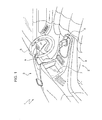
- FIG. 1 designated by the number 1 is an automobile provided with a passenger compartment 2, which can accommodate at least a driver and a front passenger seated on respective seats.
- the passenger compartment 2 is delimited at the front by a transparent windscreen and by a dashboard 3 (which is hence set in a front portion of the passenger compartment 2).
- the dashboard 3 supports an instrument panel 4 and a steering wheel 5, which is turned to control an angle of steering of the automobile 1 and is set in front of the driver in front of the instrument panel 4.
- the automobile 1 comprises an infotelematic system 6, which is designed to perform numerous functions, amongst which playing music (from a radio station or from a magnetic or else optical storage medium), using a cellphone in handsfree mode, displaying audiovisual content (for example a television programme), using satellite navigation, and using advanced functions of the on-board information system (self-diagnosis of the on-board systems, programmed maintenance, average and instantaneous fuel consumption, etc.).
- infotelematic system 6 which is designed to perform numerous functions, amongst which playing music (from a radio station or from a magnetic or else optical storage medium), using a cellphone in handsfree mode, displaying audiovisual content (for example a television programme), using satellite navigation, and using advanced functions of the on-board information system (self-diagnosis of the on-board systems, programmed maintenance, average and instantaneous fuel consumption, etc.).
- the infotelematic system 6 comprises a liquid-crystal display 7, which is normally of dimensions such that it can be integrated in a single-DIN or else double-DIN compartment and is set in a central portion of the dashboard 3 between the driver's seat and the front passenger's seat.
- the display 7 is not set in a central portion of the dashboard 3 between the driver's seat and the front passenger's seat, but is inserted in the instrument panel 4 so as to be set in front of the driver and so as to be visible to the driver through a top opening of the steering wheel 5.
- a further display is provided, which is inserted in the instrument panel 4 and normally duplicates the information appearing on the display 7 for the benefit of the driver.
- the display 7 set in a central portion of the dashboard 3 between the driver's seat and the front passenger's seat is basically used by the passengers.
- the infotelematic system 6 comprises a control device 8, which enables control of the information appearing on the display 7 and is set in a central portion of the dashboard 3 in front of the liquid-crystal display 7, and a central processing unit (not illustrated) provided with the control logic.
- the central processing unit of the infotelematic system 6 can be housed in an independent container set in a hidden position or else can be integrated together with the display 7.
- the control device 8 is of the joystick type and comprises a bar 9, which has a visible top portion 10 that is shaped so as to be guided by the user's hand (preferably it is gripped between his fingers or alternatively gripped in his hand), and a hidden bottom portion 11, which is inserted within a chamber 12 and is hinged at the bottom by means of a ball joint 13 to be able to turn freely about a central hinge point, i.e., turn freely and simultaneously about two axes coplanar and perpendicular to one another.
- the chamber 12 is closed at the top by a covering element 14, which is perforated at the centre to enable passage of the bar 9 and is made of deformable plastic material to enable movement of the bar 9 itself.
- the bar 9 normally assumes a central resting position, starting from which it can be displaced in all the directions of a plane.
- the control device 8 comprises four electromechanical or else optical sensors 15, which are arranged in the chamber 12 and are symmetrically distributed about the bottom portion 11 of the bar 9 to read the position of the bar 9 itself and in particular to detect eight significant positions: the four direct positions (forwards, backwards, right and left) and the four mixed positions (forward-right, forward-left, back-right and back-left).
- the control device 8 comprises a haptic actuator 16, which is coupled to the bottom portion 11 of the bar 9 to vary the effort necessary for displacement of the bar 9 itself.
- the haptic actuator 16 is able to supply a feedback of force to the user who grips the bar 9 for guiding displacement of the bar 9 itself.
- the haptic actuator 16 could comprise a pair of electric servo motors (one for each axis of rotation) coupled to the bar 9 by means of a gear transmission, or else the haptic actuator 16 could comprise a pair of magnetorheological or electrorheological servo motors (one for each axis of rotation) directly coupled to the bar 9.
- the haptic actuator 16 keeps the bar 9 in the central resting position.
- the bottom portion 11 of the bar 9 could be coupled to elastic elements, which are arranged in the chamber 12 and, in the absence of external forces, are designed to keep the bar 9 itself in a central resting position.
- the bar 9 carries an activation pushbutton 17, which is mounted in a horizontal top face of the bar 9.
- the user displaces the bar 9 for selecting on the display 7 the desired option from amongst the various options displayed and presses the pushbutton 17 to activate the selected option.
- the user can select the desired option (for example, by displacing a selection cursor on the desired option) and then presses the activation pushbutton 17 for activating the selected option.
- the activation pushbutton 17 is set in front of the bar 9 (hence it is not supported by the bar 9) or else it is integrated in the stem of the bar 9 (hence it is not mounted in a horizontal top face of the bar 9).
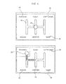
- FIG 4 two screenfuls are shown, which can be displayed on the display 7 for making the selection from among a set of selectable options 18.
- six different options 18 are displayed ("Phone", “Navi”, “Options”, “Adas”, “Media” and “Map"), which are set at the six vertices of a path 19 that has the shape of a selection scheme of a motor-vehicle gear change.
- a selection cursor 20 that is initially set in a central neutral position and is then displaced to the right and upwards with corresponding movements of the bar 9 for selecting the option 18 "Phone".
- the function of the selection cursor 20 that is displaced by the movement of the bar 9 is that of indicating a current position of selection, i.e., indicating from amongst the various options 18 the option 18 currently selected.
- appearing on the display 7 is a selection cursor 20, which is displaced by the movement of the bar 9 and indicates a current position of selection.
- the haptic actuator 16 is operated to prevent or at least render problematical (i.e., require a high force compatibly with the performance of the haptic actuator 16) displacement of the bar 9 into said position. For example, if in the screenfuls illustrated in Figure 4 , the option "Media" were not selectable (bar 9 downwards), then the haptic actuator 16 would be operated to prevent or at least render problematical displacement of the bar 9 downwards.
- the haptic actuator 16 coupled to the bar 9 is governed to allow the bar 9 itself to perform only movements that reproduce the path 19 appearing on the display 7.
- the selection cursor 20 is set in a central position of the path 19, which in this position has the possibility of performing horizontal or vertical movements, and hence the haptic actuator 16 is governed to allow the bar 9 to perform only horizontal or vertical movements (up, down, right and left) and not oblique movements.
- the selection cursor 20 is set in a lateral position of the path 19, which in this position has only the possibility of a vertical movement downwards, and hence the haptic actuator 16 is governed so as to allow the bar 9 to perform only a vertical movement downwards.
- appearing on the display 7 is a set of selectable options 18, and the position of the bar 9 of the control device 8 is detected for determining the option 18 selected by the user from amongst the selectable options 18 appearing on the display 7.
- Appearing on the display 7 is the path 19, set along which are the selectable options 18, and the haptic actuator 16 coupled to the bar 9 is governed to allow the bar 9 itself to perform only movements that reproduce the path 19 appearing on the display 7.
- haptic actuator 16 to allow the bar 9 to perform only movements that reproduce the path 19 appearing on the display 7 envisages requiring a minimum effort for displacing the bar 9 according to the path 19 appearing on the display 7 and requiring a maximum effort (i.e., the maximum possible effort enabled by the capacity of the haptic actuator 16) for displacing the bar 9 in a different way from the path 19 appearing on the display 7. It should be pointed out that the haptic actuator 16 presents physical limits, and hence a user who exerts on the bar 9 a sufficiently high force could overcome the action of the haptic actuator 16 and displace the bar 9 in a way different from what is envisaged by the path 19 appearing on the display 7.
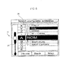
- Figure 5 illustrates a further screenful that can appear on the display 7 for making a selection from among some selectable options 18.
- seven different options 18 are displayed ("Favourite destinations”, “Recent destinations”, “Complete address”, “Atlas mode”, “Points of interest”, “Address book” and “NAVI Options") which are arranged to form a vertical list in which the options 18 themselves are set on top of one another.
- a central position corresponding, in this particular case, to the option "Atlas mode”
- the selectable options 18 are split into a top halflist (comprising "Favourite destinations", “Recent destinations” and “Complete address”), set above the central position, and a bottom halflist (comprising "Points of interest", “Address book” and “NAVI Options"), set below the central position.
- the haptic actuator 16 coupled to the bar 9 is governed to allow the bar 9 itself to perform only vertical movements downwards and upwards starting from a central position of the bar 9, and the haptic actuator 16 is governed so as to divide each arc of movement of the bar 9 downwards or upwards into a plurality of selection positions set at angular distances from one another and each of which corresponds to a respective selectable option 18 of a respective bottom or top halflist.
- the haptic actuator 16 coupled to the bar 9 is governed so as to require a peak of effort for abandoning a position of selection corresponding to a respective selectable option 18.
- each position of selection corresponding to a respective selectable option 18 constitutes a point of relative minimum of the effort necessary for displacing the bar 9.
- a further end selection position which is located in the bottom end position and corresponds to an option of return to a top menu (identified in the screenful of Figure 5 with the label "Home").
- Said feature is important in so far as it enables a user to select in a simple, fast and intuitive way the option of return to a top menu, which is one of the most widely used options.
- the selection cursor 20 is present, which is displaced by the movement of the bar 9 and indicates a current position of selection. As has been described previously, the pressure upon the activation pushbutton 17 mounted on the bar 9 is detected, and the option 18 corresponding to the position in which the selection cursor 20 is set at the moment when the activation pushbutton 17 is pressed is selected.
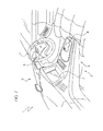
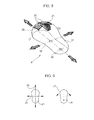
- FIG 7 illustrates the dashboard 3 provided with a different control device 8, which is of the mouse type and comprises a grippable element 21 that is shaped like the mouse of a computer.
- the grippable element 21 has in a front position a pair of pushbuttons 22 and a wheel 23 that is coupled to a haptic actuator (integrated within the grippable element 21 and not illustrated).
- the pair of pushbuttons 22 and the wheel 23 are separate from the grippable element 21 and are set in front of the grippable element 21 itself.
- the grippable element 21 presents a movement of rototranslation that envisages movements of translation in two directions 24 and 25 of translation perpendicular to one another and a rotation about an axis 26 of rotation.
- the axis 26 of rotation is set staggered with respect to the point of crossing-over of the two directions 24 and 25 of translation.
- the point of crossing-over of the two directions 24 and 25 of translation is set in a central position of the grippable element 21, whilst the axis 26 of rotation is set in a set-back position of the grippable element 21.
- the eccentricity of the axis 26 of rotation with respect to the point of crossing-over of the two directions 24 and 25 of translation enables a better control of the position of the grippable element 21 preventing a movement of translation from being erroneously imparted on the grippable element 21 instead of a movement of rotation, and vice versa.
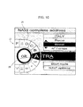
- Figures 6 and 10 illustrate two alternative screenfuls that can appear on the display 7 to provide a virtual keypad comprising an orderly succession of alphanumeric characters.
- the virtual keypad of Figures 6 and 10 comprises a path 27 closed to form a loop (i.e., in which the end of the path 27 connects up to the start of the path 27) made up of a succession of boxes 28, each of which contains a respective alphanumeric character. Appearing on the display 7 is only a part (obviously variable) of the closed path 27 presenting a limited number of boxes 28 (typically 8-12).
- the virtual keypad of Figures 6 and 10 comprises a selection window 29, which is set superimposed on the closed path 27 and highlights the box 28 of the path 27 and hence the respective alphanumeric character currently selected.
- the control device 8 the joystick control device 8 illustrated in Figures 1-3 or the mouse control device 8 illustrated in Figures 7-9 ) it is possible to scroll the closed path 27 forwards or backwards with respect to the selection window 29.
- pressure upon an activation pushbutton 17 or 22 of the control device 8 is detected in such a way as to enable selection of the alphanumeric character present within the selection window 29 at the moment of pressure upon the activation pushbutton 17 or 22.
- the movement of the bar 9 is used for scrolling the closed path 27 forwards or backwards with respect to the selection window 29.
- the haptic device 16 coupled to the bar 9 enables jumping upwards or downwards for scrolling the closed path 27 forwards or backwards with respect to the selection window 29.
- Jumping upwards or downwards envisages that, starting from a central position, the bar 9 will be displaced upwards or downwards and then return automatically in the central position (in other words, the haptic device 16 simulates the behaviour of an elastic means that tends to keep the bar 9 in the central position).
- the movements to the right and to the left of the bar 9 can be used to erase the last character selected and/or to pass to another selection menu illustrated in the right-hand part of the screenful of Figure 6 .
- the wheel 23 is used for scrolling the closed path 27 forwards or backwards with respect to the selection window 29.
- the haptic device coupled to the wheel 23 impresses a movement of jumpy rotation on the wheel 23 itself in the two directions of rotation for scrolling the closed path 27 forwards or backwards with respect to the selection window 29.
- the jumpy rotation envisages that the haptic device coupled to the wheel 23 will be governed so as to require a peak of effort for abandoning an angular position of selection.
- each angular position of selection constitutes a point of relative minimum of the effort necessary to turn the wheel 23.
- the virtual keypad of Figure 10 is not controlled by the wheel 23 (having horizontal axis of rotation) of the mouse control device 8 illustrated in Figures 7-9 , but is controlled by a turnable knob with vertical axis of rotation that constitutes a further type of control device 8 and is coupled to a haptic device for adjusting the force necessary to turn the turnable knob itself.
- scrolling of the closed path 27 with respect to the selection window 29 occurs by means of a vertical rectilinear movement of the bar 9, and hence the closed path 27 has a vertical rectilinear conformation (i.e., it extends vertically from top downwards).
- scrolling of the closed path 27 with respect to the selection window 29 occurs by means of a movement of rotation of the wheel 23, and hence the closed path 27 has a circular conformation.
- the representation on the display 7 of the closed path 27 reproduces the type of movement required for determining scrolling of the closed path 27 with respect to the selection window 29.
- the alphanumeric character is reproduced at an enlarged scale.
- each time there are determined the alphanumeric characters allowed during composition of an alphanumeric string is possible to scroll within the selection window 29 only the boxes 28 corresponding to alphanumeric characters allowed, or else it is possible to eliminate from the closed path 27 the boxes 28 corresponding to alphanumeric characters not allowed.
- the haptic device 16 is governed so as to vary its own behaviour according to what is represented on the display 7 and hence so as to adapt to what is represented on the display 7.
- the haptic device 16 is not governed always in the same way, but the way of governing the haptic device 16 is adapted each time to what is represented on the display 7.
- the control device 8 when the control device 8 has a main movement of translation, then the information (i.e., the selectable options 18) appearing on the display 7 are organized so as to be set along a path made up of rectilinear stretches, whilst, when the control device 8 has a main movement of rotation, then the information (i.e., the selectable options 18) appearing on the display 7 are organized so as to be set along a circular path.
- Figure 11 illustrates the dashboard 3 provided with a further control device 8 of the touchpad type and comprises a plane plate 30 presenting a top surface 31 in view.
- the control device 8 comprises a cross-shaped path 32, which is obtained on the top surface 31 of the plane plate 30 and is made of touch-sensitive material, four pushbuttons 33, which are obtained on the top surface 31 of the plane plate 30, are made of touch-sensitive material, and are symmetrically arranged in the four quadrants defined by the cross-shaped path 32, and a circular closed path 34, which is obtained on the top surface 31 of the plane plate 30, is made of touch-sensitive material, and surrounds the cross-shaped path 32.
- the control device 8 comprises a sensor device 35 coupled to the plane plate 30 for detecting a tactile pressure on the cross-shaped path 32, on the pushbuttons 33, and on the circular closed path 34.
- the cross-shaped path 32, the pushbuttons 33, and the circular closed path 34 are highlighted by means of a differentiation of colouring and/or a differentiation of height (i.e., said parts are set in for guiding positioning of the user's fingers) with respect to the rest of the top surface 31 of the plane plate 30.
- the cross-shaped path 32, the pushbuttons 33, and the circular closed path 34 provide the user with a visual feedback (colouring) and/or a tactile feedback (height) with respect to the rest of the top surface 31 of the plane plate 30, thus facilitating their identification.
- the plane plate 30 has at the top an aluminium plate that constitutes the top surface 31 of the plane plate 30, and the sensor device 35 comprises a piezoelectric film (or, alternatively, a capacitive film) set immediately underneath the aluminium plate and embedded within the plane plate 30.
- a piezoelectric film or, alternatively, a capacitive film
- the circular closed path 34 is not made of touch-sensitive material and constitutes the sliding path of a slider 36, which is mounted so as to slide along the circular closed path 34 under the thrust of the user's finger.
- a further sensor device 37 is provided, coupled to the plane plate 30, for detecting the position of the slider 36 along the circular closed path 34.
- the control device 8 comprises a haptic actuator 38, which is coupled to the slider 36 for varying the force necessary to displace the slider 36 itself along the circular closed path 34.
- control device 8 illustrated in Figures 12 and 13 is without the cross-shaped path 32 and comprises only the pushbuttons 33 (which can be four or else also a different number generally comprised between three and six) and the circular closed path 34.
- Figure 14 shows a screenful that can appear on the display 7 for making the selection from amongst a set of selectable options 18.
- six different options 18 are displayed ("Adas”, “Navi”, “Map”, “Media”, “Options”, “Phone") and a synoptic image 39 that reproduces the shape of the control device 8 indicating the functions associated to the four pushbuttons 33 of the control device 8 itself.
- the closed path 34 of the control device 8 it is possible to choose an option 18, whilst by pressing a pushbutton 33 of the control device 8 that carries out the function of activation it is possible to select the option 18 chosen.
- the option 18 chosen is highlighted by a selection cursor 20, which, as has already been said, is shifted according to the closed path 34 of the control device 8.
- Figure 15 illustrates a further screenful that can appear on the display 7 for making a selection from amongst some selectable options 18.
- seven different options 18 are displayed ("Favourite destinations”, “Recent destinations”, “Complete address”, “Atlas mode”, “Points of interest”, “Address book” and “NAVI Options"), which are ordered so as to form a vertical list in which the options 18 themselves are set on top of one another.
- a synoptic image 39 is displayed, which reproduces the shape of the control device 8 indicating the functions associated to the four pushbuttons 33 of the control device 8 itself.
- the closed path 34 of the control device 8 it is possible to choose an option 18, whilst by pressing a pushbutton 33 of the control device 8 that carries out the function of activation it is possible to select the option 18 chosen.
- the option 18 chosen is highlighted by a selection cursor 20, which, as has already been said, is displaced according to the closed path 34 of the control device 8.
- Figures 16 and 17 illustrate two alternative screenfuls that can appear on the display 7 for providing a virtual keypad comprising an orderly succession of alphanumeric characters.
- a synoptic image 39 is displayed, which reproduces the shape of the control device 8 indicating the functions associated to the four pushbuttons 33 of the control device 8 itself.
- the virtual keypad of Figures 16 and 17 is altogether similar to the virtual keypad of Figures 6 and 10 and comprises a closed-loop path 27 (i.e., the end of the path 27 connected up to the start of the path 27) made up of a succession of boxes 28, each of which contains a respective alphanumeric character. Appearing on the display 7 is only a part (obviously variable) of the closed path 27 presenting a limited number of boxes 28 (typically 8-12).
- the virtual keypad of Figures 16 and 17 comprises a selection window 29, which is set on top of the closed path 27 and highlights the box 28 of the path 27 and hence the respective alphanumeric character currently selected.
- the closed path 34 of the control device 8 By means of the closed path 34 of the control device 8, it is possible to scroll forwards or backwards the closed path 27 with respect to the selection window 29.
- the pressure upon an activation pushbutton 33 of the control device 8 is detected in such a way as to select the alphanumeric character present within the selection window 29 at the moment of pressure upon the activation pushbutton 33 (another key 33 of the control device 8 can be used for erasing the last selected character).
- each time there are determined the alphanumeric characters allowed during composition of an alphanumeric string is possible to scroll within the selection window 29 only the boxes 28 corresponding to alphanumeric characters allowed, or else it is possible to eliminate from the closed path 27 the boxes 28 corresponding to alphanumeric characters not allowed.
- the control device 8 illustrated in Figures 11 , 12 and 13 presents numerous advantages in so far as it has very contained dimensions (in particular, it is extremely slim) and hence is simple to place and install in a dashboard of a motor vehicle and moreover presents a high reliability, given that it does not present moving parts (embodiment of Figure 12 ) or else it has a very limited number of moving parts (embodiment of Figure 13 ).
- the infotelematic system 1 described above presents numerous advantages, in so far as it is easy and inexpensive to produce and above all enables the driver to control the infotelematic system 1 in an ergonomic way, i.e., in a way convenient to use (without requiring the driver to take his eyes off the road so as to look at the control device) and simple to learn.
- infotelematic system 1 described above can be used in any other type of road vehicle, such as, for example, a bus, a van, or a lorry.
Landscapes
- Engineering & Computer Science (AREA)
- General Engineering & Computer Science (AREA)
- Theoretical Computer Science (AREA)
- Human Computer Interaction (AREA)
- Physics & Mathematics (AREA)
- General Physics & Mathematics (AREA)
- Chemical & Material Sciences (AREA)
- Combustion & Propulsion (AREA)
- Transportation (AREA)
- Mechanical Engineering (AREA)
- User Interface Of Digital Computer (AREA)
- Fittings On The Vehicle Exterior For Carrying Loads, And Devices For Holding Or Mounting Articles (AREA)
- Vehicle Body Suspensions (AREA)
- Position Input By Displaying (AREA)
- Mechanical Control Devices (AREA)
Abstract
Description
- The present invention relates to a method for control of an infotelematic system for a road vehicle for choosing from amongst a number of selectable options.
- The present invention finds advantageous application in an automobile, to which the ensuing description will make explicit reference, without this implying any loss of generality.
- With the progress of electronic systems, in the last few years there has been a constant increase in the amount of information that is made available to the driver of an automobile. For example, alongside the traditional possibility of playing music (from a radio station or from a magnetic or else optical storage medium) there has progressively appeared the possibility of using a cellphone in handsfree mode for displaying audiovisual content (for example, a television programme), using the satellite navigation possibly with updating in real time on the traffic conditions, navigating through the Internet, using advanced functions of an on-board information system, etc.
- Consequently, there is increasingly felt both the need to organize and display the various information in such a way that the driver will be able to find rapidly all the desired information, without being excessively distracted from driving, and to enable the driver to control the infotelematic system in a way that is ergonomic, i.e., simple (so that he will not have to draw his attention away from driving) and intuitive (so as not to require a long learning process). Normally, a modern infotelematic system for an automobile comprises a liquid-crystal display set on the dashboard of the automobile and a control device typically set in the proximity of the liquid-crystal display and designed to control the various functions available. In the majority of automobiles on the market, the control device comprises a plurality of pushbuttons, which are set around the liquid-crystal display. However, this kind of control devices is far from ergonomic in so far as it is inconvenient to use (i.e., it requires the driver to take his eyes off the road to see which pushbutton to press) and is often particularly awkward to learn (i.e., it takes some time to learn how to use all the various functions).
-
EP1243997A2 discloses a vehicle-mounted device control unit provided with an electrical appliance selection switch for selecting an electrical appliance whose function is to be regulated, a manual input device for regulating various functions of the electrical appliance selected with the switch; the manual input device is provided with knobs, actuators for loading external forces on the knobs, and detecting devices for detecting the manipulated states of the knobs, and a controller drives the actuators and carries out force feedback to a user. -
WO0034067A1 -
EP1213165A2 discloses a rotating knob provided on a decorative panel of a controller unit in such a way as to be able to rotate around a shaft center; three guideholes are provided along the same virtual circle drawn around the shaft center, and sliding knobs are respectively provided in the guide holes in such a manner as to perform a sliding operation. - The aim of the present invention is to provide a method for control of an infotelematic system for a road vehicle for choosing from amongst a number of selectable options, said method being convenient and inexpensive to produce and being free from the drawbacks described above.
- In accordance with the present invention, a method for control of an infotelematic system for a road vehicle for choosing from amongst a number of selectable options is provided according to what is set forth in the annexed claims.
- The present invention will now be described with reference to the annexed drawings, which illustrate some non-limiting examples of embodiment thereof, and in which:
-
Figure 1 is a schematic and perspective view of a dashboard of an automobile provided with an infotelematic system that is controlled in accordance with the present invention; -
Figure 2 is a schematic view at an enlarged scale of a control device of the infotelematic system ofFigure 1 ; -
Figure 3 is a schematic view partially in cross section of the control device ofFigure 2 ; -
Figures 4 ,5 and6 illustrate some screenfuls that are displayed in a liquid-crystal display of the infotelematic system ofFigure 1 ; -
Figure 7 is a schematic and perspective view of a dashboard of an automobile provided with an alternative embodiment of the infotelematic system; -
Figure 8 is a schematic view at an enlarged scale of a control device of the infotelematic system ofFigure 7 ; -
Figure 9 is a schematic illustration of the possibilities of movement of the control device ofFigure 8 ; -
Figure 10 illustrates a screenful that is displayed in a liquid-crystal display of the infotelematic system ofFigure 7 ; -
Figure 11 is a schematic and perspective view of a dashboard of an automobile provided with a further embodiment of the infotelematic system; -
Figure 12 is a schematic plan view at an enlarged scale of a control device of the infotelematic system ofFigure 11 ; -
Figure 13 illustrates a variant of the control device ofFigure 12 ; and -
Figures 14-17 illustrate some screenfuls that are displayed in a liquid-crystal display of the infotelematic system ofFigure 11 . - In
Figure 1 , designated by thenumber 1 is an automobile provided with apassenger compartment 2, which can accommodate at least a driver and a front passenger seated on respective seats. Thepassenger compartment 2 is delimited at the front by a transparent windscreen and by a dashboard 3 (which is hence set in a front portion of the passenger compartment 2). In front of the driver, thedashboard 3 supports aninstrument panel 4 and asteering wheel 5, which is turned to control an angle of steering of theautomobile 1 and is set in front of the driver in front of theinstrument panel 4. - The
automobile 1 comprises aninfotelematic system 6, which is designed to perform numerous functions, amongst which playing music (from a radio station or from a magnetic or else optical storage medium), using a cellphone in handsfree mode, displaying audiovisual content (for example a television programme), using satellite navigation, and using advanced functions of the on-board information system (self-diagnosis of the on-board systems, programmed maintenance, average and instantaneous fuel consumption, etc.). - The
infotelematic system 6 comprises a liquid-crystal display 7, which is normally of dimensions such that it can be integrated in a single-DIN or else double-DIN compartment and is set in a central portion of thedashboard 3 between the driver's seat and the front passenger's seat. According to a different embodiment (not illustrated), thedisplay 7 is not set in a central portion of thedashboard 3 between the driver's seat and the front passenger's seat, but is inserted in theinstrument panel 4 so as to be set in front of the driver and so as to be visible to the driver through a top opening of thesteering wheel 5. According to a further embodiment (not illustrated), in addition to the display 7 a further display is provided, which is inserted in theinstrument panel 4 and normally duplicates the information appearing on thedisplay 7 for the benefit of the driver. In this case thedisplay 7 set in a central portion of thedashboard 3 between the driver's seat and the front passenger's seat is basically used by the passengers. - In addition, the
infotelematic system 6 comprises acontrol device 8, which enables control of the information appearing on thedisplay 7 and is set in a central portion of thedashboard 3 in front of the liquid-crystal display 7, and a central processing unit (not illustrated) provided with the control logic. The central processing unit of theinfotelematic system 6 can be housed in an independent container set in a hidden position or else can be integrated together with thedisplay 7. - According to what is illustrated in
Figures 2 and3 , thecontrol device 8 is of the joystick type and comprises a bar 9, which has avisible top portion 10 that is shaped so as to be guided by the user's hand (preferably it is gripped between his fingers or alternatively gripped in his hand), and ahidden bottom portion 11, which is inserted within achamber 12 and is hinged at the bottom by means of aball joint 13 to be able to turn freely about a central hinge point, i.e., turn freely and simultaneously about two axes coplanar and perpendicular to one another. Thechamber 12 is closed at the top by acovering element 14, which is perforated at the centre to enable passage of the bar 9 and is made of deformable plastic material to enable movement of the bar 9 itself. - The bar 9 normally assumes a central resting position, starting from which it can be displaced in all the directions of a plane. The
control device 8 comprises four electromechanical or elseoptical sensors 15, which are arranged in thechamber 12 and are symmetrically distributed about thebottom portion 11 of the bar 9 to read the position of the bar 9 itself and in particular to detect eight significant positions: the four direct positions (forwards, backwards, right and left) and the four mixed positions (forward-right, forward-left, back-right and back-left). - In addition, the
control device 8 comprises ahaptic actuator 16, which is coupled to thebottom portion 11 of the bar 9 to vary the effort necessary for displacement of the bar 9 itself. In other words, thehaptic actuator 16 is able to supply a feedback of force to the user who grips the bar 9 for guiding displacement of the bar 9 itself. By way of example, thehaptic actuator 16 could comprise a pair of electric servo motors (one for each axis of rotation) coupled to the bar 9 by means of a gear transmission, or else thehaptic actuator 16 could comprise a pair of magnetorheological or electrorheological servo motors (one for each axis of rotation) directly coupled to the bar 9. Preferably, thehaptic actuator 16 keeps the bar 9 in the central resting position. Alternatively, thebottom portion 11 of the bar 9 could be coupled to elastic elements, which are arranged in thechamber 12 and, in the absence of external forces, are designed to keep the bar 9 itself in a central resting position. - According to a preferred embodiment, the bar 9 carries an
activation pushbutton 17, which is mounted in a horizontal top face of the bar 9. Preferably, the user displaces the bar 9 for selecting on thedisplay 7 the desired option from amongst the various options displayed and presses thepushbutton 17 to activate the selected option. In other words, when on the display 7 a number of options are displayed by displacement of the bar 9, the user can select the desired option (for example, by displacing a selection cursor on the desired option) and then presses theactivation pushbutton 17 for activating the selected option. According to two different embodiments (not illustrated), theactivation pushbutton 17 is set in front of the bar 9 (hence it is not supported by the bar 9) or else it is integrated in the stem of the bar 9 (hence it is not mounted in a horizontal top face of the bar 9). - In
Figure 4 two screenfuls are shown, which can be displayed on thedisplay 7 for making the selection from among a set ofselectable options 18. In the two screenfuls illustrated inFigure 4 sixdifferent options 18 are displayed ("Phone", "Navi", "Options", "Adas", "Media" and "Map"), which are set at the six vertices of apath 19 that has the shape of a selection scheme of a motor-vehicle gear change. In the two screenfuls, it is possible to appreciate the position of aselection cursor 20 that is initially set in a central neutral position and is then displaced to the right and upwards with corresponding movements of the bar 9 for selecting theoption 18 "Phone". The function of theselection cursor 20 that is displaced by the movement of the bar 9 is that of indicating a current position of selection, i.e., indicating from amongst thevarious options 18 theoption 18 currently selected. In other words, appearing on thedisplay 7 is aselection cursor 20, which is displaced by the movement of the bar 9 and indicates a current position of selection. When theactivation pushbutton 17 mounted on the bar 9 is pressed, theoption 18 is selected corresponding to the position in which theselection cursor 20 is set at the moment when theactivation pushbutton 17 is pressed. - In the case where a certain position of the bar 9 does not correspond to any selectable option, the
haptic actuator 16 is operated to prevent or at least render problematical (i.e., require a high force compatibly with the performance of the haptic actuator 16) displacement of the bar 9 into said position. For example, if in the screenfuls illustrated inFigure 4 , the option "Media" were not selectable (bar 9 downwards), then thehaptic actuator 16 would be operated to prevent or at least render problematical displacement of the bar 9 downwards. - In addition, the
haptic actuator 16 coupled to the bar 9 is governed to allow the bar 9 itself to perform only movements that reproduce thepath 19 appearing on thedisplay 7. For example, in the top screenful ofFigure 4 theselection cursor 20 is set in a central position of thepath 19, which in this position has the possibility of performing horizontal or vertical movements, and hence thehaptic actuator 16 is governed to allow the bar 9 to perform only horizontal or vertical movements (up, down, right and left) and not oblique movements. In the bottom screenful ofFigure 4 , theselection cursor 20 is set in a lateral position of thepath 19, which in this position has only the possibility of a vertical movement downwards, and hence thehaptic actuator 16 is governed so as to allow the bar 9 to perform only a vertical movement downwards. - In other words, appearing on the
display 7 is a set ofselectable options 18, and the position of the bar 9 of thecontrol device 8 is detected for determining theoption 18 selected by the user from amongst theselectable options 18 appearing on thedisplay 7. Appearing on thedisplay 7 is thepath 19, set along which are theselectable options 18, and thehaptic actuator 16 coupled to the bar 9 is governed to allow the bar 9 itself to perform only movements that reproduce thepath 19 appearing on thedisplay 7. - Governing the
haptic actuator 16 to allow the bar 9 to perform only movements that reproduce thepath 19 appearing on thedisplay 7 envisages requiring a minimum effort for displacing the bar 9 according to thepath 19 appearing on thedisplay 7 and requiring a maximum effort (i.e., the maximum possible effort enabled by the capacity of the haptic actuator 16) for displacing the bar 9 in a different way from thepath 19 appearing on thedisplay 7. It should be pointed out that thehaptic actuator 16 presents physical limits, and hence a user who exerts on the bar 9 a sufficiently high force could overcome the action of thehaptic actuator 16 and displace the bar 9 in a way different from what is envisaged by thepath 19 appearing on thedisplay 7. -
Figure 5 illustrates a further screenful that can appear on thedisplay 7 for making a selection from among someselectable options 18. In the screenful illustrated inFigure 5 sevendifferent options 18 are displayed ("Favourite destinations", "Recent destinations", "Complete address", "Atlas mode", "Points of interest", "Address book" and "NAVI Options") which are arranged to form a vertical list in which theoptions 18 themselves are set on top of one another. In this case, identified in the list of theselectable options 18 is a central position (corresponding, in this particular case, to the option "Atlas mode"), and theselectable options 18 are split into a top halflist (comprising "Favourite destinations", "Recent destinations" and "Complete address"), set above the central position, and a bottom halflist (comprising "Points of interest", "Address book" and "NAVI Options"), set below the central position. In addition, thehaptic actuator 16 coupled to the bar 9 is governed to allow the bar 9 itself to perform only vertical movements downwards and upwards starting from a central position of the bar 9, and thehaptic actuator 16 is governed so as to divide each arc of movement of the bar 9 downwards or upwards into a plurality of selection positions set at angular distances from one another and each of which corresponds to a respectiveselectable option 18 of a respective bottom or top halflist. By way of example, if the arc of movement of the bar 9 envisages, starting from a central position, a rotation through 30° in the two directions, to a rotation through 10° downwards there corresponds "Points of interest", to a rotation through 20° downwards there corresponds "Address book", and to a rotation through 30° downwards there corresponds "NAVI Options"; likewise, to a rotation through 10° upwards there corresponds "Complete address", to a rotation through 20° upwards there corresponds "Recent destinations", and to a rotation through 30° upwards there corresponds "Favourite destinations". - It should be emphasized that the layout of the screenful illustrated in
Figure 5 and described above enables minimization of the movements made by the user's hand to complete the possible selections. - According to a preferred embodiment, the
haptic actuator 16 coupled to the bar 9 is governed so as to require a peak of effort for abandoning a position of selection corresponding to a respectiveselectable option 18. In other words, each position of selection corresponding to a respectiveselectable option 18 constitutes a point of relative minimum of the effort necessary for displacing the bar 9. In this way, for a user it is simple and intuitive to identify a position of selection corresponding to a respectiveselectable option 18. In the arc of movement of the bar 9 downwards there could be inserted a further end selection position, which is located in the bottom end position and corresponds to an option of return to a top menu (identified in the screenful ofFigure 5 with the label "Home"). Said feature is important in so far as it enables a user to select in a simple, fast and intuitive way the option of return to a top menu, which is one of the most widely used options. - Also in the screenful of
Figure 5 theselection cursor 20 is present, which is displaced by the movement of the bar 9 and indicates a current position of selection. As has been described previously, the pressure upon theactivation pushbutton 17 mounted on the bar 9 is detected, and theoption 18 corresponding to the position in which theselection cursor 20 is set at the moment when theactivation pushbutton 17 is pressed is selected. -
Figure 7 illustrates thedashboard 3 provided with adifferent control device 8, which is of the mouse type and comprises agrippable element 21 that is shaped like the mouse of a computer. According to what is illustrated inFigures 8 and 9 , thegrippable element 21 has in a front position a pair ofpushbuttons 22 and awheel 23 that is coupled to a haptic actuator (integrated within thegrippable element 21 and not illustrated). According to a different embodiment (not illustrated), the pair ofpushbuttons 22 and thewheel 23 are separate from thegrippable element 21 and are set in front of thegrippable element 21 itself. - The
grippable element 21 presents a movement of rototranslation that envisages movements of translation in twodirections axis 26 of rotation. According to a preferred embodiment, theaxis 26 of rotation is set staggered with respect to the point of crossing-over of the twodirections directions grippable element 21, whilst theaxis 26 of rotation is set in a set-back position of thegrippable element 21. The eccentricity of theaxis 26 of rotation with respect to the point of crossing-over of the twodirections grippable element 21 preventing a movement of translation from being erroneously imparted on thegrippable element 21 instead of a movement of rotation, and vice versa. -
Figures 6 and10 illustrate two alternative screenfuls that can appear on thedisplay 7 to provide a virtual keypad comprising an orderly succession of alphanumeric characters. The virtual keypad ofFigures 6 and10 comprises apath 27 closed to form a loop (i.e., in which the end of thepath 27 connects up to the start of the path 27) made up of a succession ofboxes 28, each of which contains a respective alphanumeric character. Appearing on thedisplay 7 is only a part (obviously variable) of theclosed path 27 presenting a limited number of boxes 28 (typically 8-12). - In addition, the virtual keypad of
Figures 6 and10 comprises aselection window 29, which is set superimposed on theclosed path 27 and highlights thebox 28 of thepath 27 and hence the respective alphanumeric character currently selected. By means of the control device 8 (thejoystick control device 8 illustrated inFigures 1-3 or themouse control device 8 illustrated inFigures 7-9 ) it is possible to scroll theclosed path 27 forwards or backwards with respect to theselection window 29. In addition, pressure upon anactivation pushbutton control device 8 is detected in such a way as to enable selection of the alphanumeric character present within theselection window 29 at the moment of pressure upon theactivation pushbutton - By means of the
joystick control device 8 illustrated inFigures 1-3 , the movement of the bar 9 is used for scrolling theclosed path 27 forwards or backwards with respect to theselection window 29. In this case, thehaptic device 16 coupled to the bar 9 enables jumping upwards or downwards for scrolling theclosed path 27 forwards or backwards with respect to theselection window 29. Jumping upwards or downwards envisages that, starting from a central position, the bar 9 will be displaced upwards or downwards and then return automatically in the central position (in other words, thehaptic device 16 simulates the behaviour of an elastic means that tends to keep the bar 9 in the central position). The movements to the right and to the left of the bar 9 can be used to erase the last character selected and/or to pass to another selection menu illustrated in the right-hand part of the screenful ofFigure 6 . - By means of the
mouse control device 8 illustrated inFigures 7-9 , thewheel 23 is used for scrolling theclosed path 27 forwards or backwards with respect to theselection window 29. In this case, the haptic device coupled to thewheel 23 impresses a movement of jumpy rotation on thewheel 23 itself in the two directions of rotation for scrolling theclosed path 27 forwards or backwards with respect to theselection window 29. The jumpy rotation envisages that the haptic device coupled to thewheel 23 will be governed so as to require a peak of effort for abandoning an angular position of selection. In other words, each angular position of selection constitutes a point of relative minimum of the effort necessary to turn thewheel 23. - According to a different embodiment (not illustrated), the virtual keypad of
Figure 10 is not controlled by the wheel 23 (having horizontal axis of rotation) of themouse control device 8 illustrated inFigures 7-9 , but is controlled by a turnable knob with vertical axis of rotation that constitutes a further type ofcontrol device 8 and is coupled to a haptic device for adjusting the force necessary to turn the turnable knob itself. - It should be noted that in the screenful illustrated in
Figure 6 , scrolling of theclosed path 27 with respect to theselection window 29 occurs by means of a vertical rectilinear movement of the bar 9, and hence theclosed path 27 has a vertical rectilinear conformation (i.e., it extends vertically from top downwards). Instead, in the screenful illustrated inFigure 10 , scrolling of theclosed path 27 with respect to theselection window 29 occurs by means of a movement of rotation of thewheel 23, and hence theclosed path 27 has a circular conformation. In this way, the representation on thedisplay 7 of theclosed path 27 reproduces the type of movement required for determining scrolling of theclosed path 27 with respect to theselection window 29. - Preferably, as illustrated in
Figures 6 and10 , within theselection window 29, the alphanumeric character is reproduced at an enlarged scale. - According to a preferred embodiment, each time there are determined the alphanumeric characters allowed during composition of an alphanumeric string. In this case, it is possible to scroll within the
selection window 29 only theboxes 28 corresponding to alphanumeric characters allowed, or else it is possible to eliminate from theclosed path 27 theboxes 28 corresponding to alphanumeric characters not allowed. - According to what has been described above, it is evident that the
haptic device 16 is governed so as to vary its own behaviour according to what is represented on thedisplay 7 and hence so as to adapt to what is represented on thedisplay 7. In other words, thehaptic device 16 is not governed always in the same way, but the way of governing thehaptic device 16 is adapted each time to what is represented on thedisplay 7. - In addition, according to what is described above, it is evident that what appears on the
display 7 is always adapted to the shape and above all the possible movements of thecontrol device 8 in such a way that, for the user who is looking at thedisplay 7 it will be intuitive and readily understandable which movements he has to impress upon thecontrol device 8 to navigate through the information (i.e., the selectable options 18) appearing on thedisplay 7. In other words, when thecontrol device 8 has a main movement of translation, then the information (i.e., the selectable options 18) appearing on thedisplay 7 are organized so as to be set along a path made up of rectilinear stretches, whilst, when thecontrol device 8 has a main movement of rotation, then the information (i.e., the selectable options 18) appearing on thedisplay 7 are organized so as to be set along a circular path. -
Figure 11 illustrates thedashboard 3 provided with afurther control device 8 of the touchpad type and comprises aplane plate 30 presenting atop surface 31 in view. - According to what is illustrated in
Figure 12 , thecontrol device 8 comprises across-shaped path 32, which is obtained on thetop surface 31 of theplane plate 30 and is made of touch-sensitive material, fourpushbuttons 33, which are obtained on thetop surface 31 of theplane plate 30, are made of touch-sensitive material, and are symmetrically arranged in the four quadrants defined by thecross-shaped path 32, and a circularclosed path 34, which is obtained on thetop surface 31 of theplane plate 30, is made of touch-sensitive material, and surrounds thecross-shaped path 32. In addition, thecontrol device 8 comprises asensor device 35 coupled to theplane plate 30 for detecting a tactile pressure on thecross-shaped path 32, on thepushbuttons 33, and on the circularclosed path 34. - Preferably, the
cross-shaped path 32, thepushbuttons 33, and the circularclosed path 34 are highlighted by means of a differentiation of colouring and/or a differentiation of height (i.e., said parts are set in for guiding positioning of the user's fingers) with respect to the rest of thetop surface 31 of theplane plate 30. In this way, thecross-shaped path 32, thepushbuttons 33, and the circularclosed path 34 provide the user with a visual feedback (colouring) and/or a tactile feedback (height) with respect to the rest of thetop surface 31 of theplane plate 30, thus facilitating their identification. - Preferably, the
plane plate 30 has at the top an aluminium plate that constitutes thetop surface 31 of theplane plate 30, and thesensor device 35 comprises a piezoelectric film (or, alternatively, a capacitive film) set immediately underneath the aluminium plate and embedded within theplane plate 30. - According to the variant illustrated in
Figure 13 , the circularclosed path 34 is not made of touch-sensitive material and constitutes the sliding path of aslider 36, which is mounted so as to slide along the circularclosed path 34 under the thrust of the user's finger. Afurther sensor device 37 is provided, coupled to theplane plate 30, for detecting the position of theslider 36 along the circularclosed path 34. Preferably, thecontrol device 8 comprises ahaptic actuator 38, which is coupled to theslider 36 for varying the force necessary to displace theslider 36 itself along the circularclosed path 34. - According to a different embodiment (not illustrated), the
control device 8 illustrated inFigures 12 and 13 is without thecross-shaped path 32 and comprises only the pushbuttons 33 (which can be four or else also a different number generally comprised between three and six) and the circularclosed path 34. -
Figure 14 shows a screenful that can appear on thedisplay 7 for making the selection from amongst a set ofselectable options 18. In the screenful illustrated inFigure 14 sixdifferent options 18 are displayed ("Adas", "Navi", "Map", "Media", "Options", "Phone") and asynoptic image 39 that reproduces the shape of thecontrol device 8 indicating the functions associated to the fourpushbuttons 33 of thecontrol device 8 itself. In particular, by using theclosed path 34 of thecontrol device 8 it is possible to choose anoption 18, whilst by pressing apushbutton 33 of thecontrol device 8 that carries out the function of activation it is possible to select theoption 18 chosen. In particular, theoption 18 chosen is highlighted by aselection cursor 20, which, as has already been said, is shifted according to theclosed path 34 of thecontrol device 8. -
Figure 15 illustrates a further screenful that can appear on thedisplay 7 for making a selection from amongst someselectable options 18. In the screenful illustrated inFigure 15 sevendifferent options 18 are displayed ("Favourite destinations", "Recent destinations", "Complete address", "Atlas mode", "Points of interest", "Address book" and "NAVI Options"), which are ordered so as to form a vertical list in which theoptions 18 themselves are set on top of one another. In addition, in the screenful illustrated inFigure 15 asynoptic image 39 is displayed, which reproduces the shape of thecontrol device 8 indicating the functions associated to the fourpushbuttons 33 of thecontrol device 8 itself. In particular, by using theclosed path 34 of thecontrol device 8 it is possible to choose anoption 18, whilst by pressing apushbutton 33 of thecontrol device 8 that carries out the function of activation it is possible to select theoption 18 chosen. In particular, theoption 18 chosen is highlighted by aselection cursor 20, which, as has already been said, is displaced according to theclosed path 34 of thecontrol device 8. -
Figures 16 and 17 illustrate two alternative screenfuls that can appear on thedisplay 7 for providing a virtual keypad comprising an orderly succession of alphanumeric characters. In the screenfuls illustrated inFigures 16 and 17 also asynoptic image 39 is displayed, which reproduces the shape of thecontrol device 8 indicating the functions associated to the fourpushbuttons 33 of thecontrol device 8 itself. The virtual keypad ofFigures 16 and 17 is altogether similar to the virtual keypad ofFigures 6 and10 and comprises a closed-loop path 27 (i.e., the end of thepath 27 connected up to the start of the path 27) made up of a succession ofboxes 28, each of which contains a respective alphanumeric character. Appearing on thedisplay 7 is only a part (obviously variable) of theclosed path 27 presenting a limited number of boxes 28 (typically 8-12). - In addition, the virtual keypad of
Figures 16 and 17 comprises aselection window 29, which is set on top of theclosed path 27 and highlights thebox 28 of thepath 27 and hence the respective alphanumeric character currently selected. By means of theclosed path 34 of thecontrol device 8, it is possible to scroll forwards or backwards theclosed path 27 with respect to theselection window 29. In addition, the pressure upon anactivation pushbutton 33 of thecontrol device 8 is detected in such a way as to select the alphanumeric character present within theselection window 29 at the moment of pressure upon the activation pushbutton 33 (another key 33 of thecontrol device 8 can be used for erasing the last selected character). - Preferably, as illustrated in
Figures 16 and 17 , within theselection window 29 the alphanumeric character is reproduced at an enlarged scale. - According to a preferred embodiment, each time there are determined the alphanumeric characters allowed during composition of an alphanumeric string. In this case, it is possible to scroll within the
selection window 29 only theboxes 28 corresponding to alphanumeric characters allowed, or else it is possible to eliminate from theclosed path 27 theboxes 28 corresponding to alphanumeric characters not allowed. - The
control device 8 illustrated inFigures 11 ,12 and 13 presents numerous advantages in so far as it has very contained dimensions (in particular, it is extremely slim) and hence is simple to place and install in a dashboard of a motor vehicle and moreover presents a high reliability, given that it does not present moving parts (embodiment ofFigure 12 ) or else it has a very limited number of moving parts (embodiment ofFigure 13 ). - The
infotelematic system 1 described above presents numerous advantages, in so far as it is easy and inexpensive to produce and above all enables the driver to control theinfotelematic system 1 in an ergonomic way, i.e., in a way convenient to use (without requiring the driver to take his eyes off the road so as to look at the control device) and simple to learn. - In the light of the numerous advantages presented, the
infotelematic system 1 described above can be used in any other type of road vehicle, such as, for example, a bus, a van, or a lorry.
Claims (5)
- A method for control of an infotelematic system (1) for a road vehicle for choosing from amongst a number of selectable options (18); the control method comprising the steps of:displaying on a display (7) a set of selectable options (18) ordered so as to form a vertical list in which the options (18) are set on top of one another; anddetecting the position of a bar (9) of a control device (8) of the joystick type for determining the option (18) selected by the user from amongst the selectable options (18) appearing on the display (7);the control method being characterized in that it comprises the further steps of:identifying a central position in the list of the selectable options (18);dividing the selectable options (18) into a top halflist set above the central position and a bottom halflist set below the central position; andgoverning a haptic actuator (16) coupled to the bar (9) to allow the bar (9) to perform only vertical movements downwards and upwards starting from a central position of the bar (9), and dividing each arc of movement of the bar (9) downwards or upwards into a plurality of positions of selection, which are set at an angular distance from one another and each of which corresponds to a respective selectable option (18) of a respective bottom or top halflist.
- The control method according to Claim 1, comprising the further step of governing the haptic actuator (16) coupled to the bar (9) so as to require a peak of effort for abandoning a position of selection corresponding to a respective selectable option (18).
- The control method according to Claim 1 or 2, wherein in the arc of movement of the bar (9) downwards a further end selection position is inserted, which is set in the bottom end position and corresponds to an option of return to a top menu.
- The control method according to Claim 1, 2 or 3, comprising the further step of displaying on the display (7) a selection cursor (20), which is displaced by the movement of the bar (9) and indicates a current position of selection.
- The control method according to Claim 4, comprising the further steps of:detecting the pressure upon an activation pushbutton (17) mounted on the bar (9); andselecting the option (18) corresponding to the position in which the selection cursor (20) is set at the moment when the activation pushbutton (17) is pressed.
Applications Claiming Priority (2)
| Application Number | Priority Date | Filing Date | Title |
|---|---|---|---|
| IT000656A ITBO20070656A1 (en) | 2007-09-26 | 2007-09-26 | INFOTELEMATIC SYSTEM FOR A ROAD VEHICLE |
| EP20080832999 EP2195183B1 (en) | 2007-09-26 | 2008-09-25 | Infotelematic system for a road vehicle |
Related Parent Applications (3)
| Application Number | Title | Priority Date | Filing Date |
|---|---|---|---|
| EP08832999.0 Division | 2008-09-25 | ||
| EP20080832999 Division EP2195183B1 (en) | 2007-09-26 | 2008-09-25 | Infotelematic system for a road vehicle |
| EP20080832999 Division-Into EP2195183B1 (en) | 2007-09-26 | 2008-09-25 | Infotelematic system for a road vehicle |
Publications (2)
| Publication Number | Publication Date |
|---|---|
| EP2666661A1 true EP2666661A1 (en) | 2013-11-27 |
| EP2666661B1 EP2666661B1 (en) | 2016-04-13 |
Family
ID=40316237
Family Applications (2)
| Application Number | Title | Priority Date | Filing Date |
|---|---|---|---|
| EP20080832999 Active EP2195183B1 (en) | 2007-09-26 | 2008-09-25 | Infotelematic system for a road vehicle |
| EP13180906.3A Active EP2666661B1 (en) | 2007-09-26 | 2008-09-25 | Method for control of an infotelematic system for a road vehicle for choosing from amongst a number of selectable options |
Family Applications Before (1)
| Application Number | Title | Priority Date | Filing Date |
|---|---|---|---|
| EP20080832999 Active EP2195183B1 (en) | 2007-09-26 | 2008-09-25 | Infotelematic system for a road vehicle |
Country Status (4)
| Country | Link |
|---|---|
| US (1) | US9120381B2 (en) |
| EP (2) | EP2195183B1 (en) |
| IT (1) | ITBO20070656A1 (en) |
| WO (1) | WO2009040643A2 (en) |
Families Citing this family (21)
| Publication number | Priority date | Publication date | Assignee | Title |
|---|---|---|---|---|
| DE102010012239B4 (en) * | 2010-03-22 | 2023-11-30 | Volkswagen Ag | Operating and display device for a motor vehicle |
| USD678848S1 (en) | 2010-09-01 | 2013-03-26 | Lectronix, Inc. | Center console single hand controller |
| US9645986B2 (en) | 2011-02-24 | 2017-05-09 | Google Inc. | Method, medium, and system for creating an electronic book with an umbrella policy |
| US9575946B2 (en) | 2011-05-23 | 2017-02-21 | Nuance Communications, Inc. | Text browsing, editing and correction methods for automotive applications |
| US20130069488A1 (en) * | 2011-07-01 | 2013-03-21 | Lockheed Martin Corporation | Piezoelectric pressure sensitive transducer apparatus and method |
| US9055509B2 (en) | 2011-12-21 | 2015-06-09 | Nuance Communications, Inc. | Situation-aware message presentation for automotive messaging |
| US8903714B2 (en) | 2011-12-21 | 2014-12-02 | Nuance Communications, Inc. | Concept search and semantic annotation for mobile messaging |
| US20130285735A1 (en) * | 2012-04-30 | 2013-10-31 | Delphi Technologies, Inc. | Operator control assembly |
| US20140191558A1 (en) * | 2013-01-08 | 2014-07-10 | Caterpillar Inc. | Operator panel for a machine |
| DE102013004246A1 (en) * | 2013-03-12 | 2014-09-18 | Audi Ag | A device associated with a vehicle with spelling means - completion mark |
| USD749034S1 (en) * | 2014-10-13 | 2016-02-09 | Gulfstream Aerospace Corporation | Aircraft parking brake handle |
| USD772780S1 (en) * | 2014-10-14 | 2016-11-29 | Gulfstream Aerospace Corporation | Aircraft parking brake handle |
| US9495088B2 (en) | 2014-12-26 | 2016-11-15 | Alpine Electronics, Inc | Text entry method with character input slider |
| US9862099B1 (en) * | 2015-06-22 | 2018-01-09 | X Development Llc | Haptic controller with touch-sensitive control knob |
| JP6533142B2 (en) * | 2015-10-14 | 2019-06-19 | 株式会社東海理化電機製作所 | Shift device |
| KR102437218B1 (en) * | 2017-10-16 | 2022-08-29 | 현대자동차주식회사 | Vehicle, and control method for the same |
| US11868171B2 (en) * | 2020-11-20 | 2024-01-09 | T-Mobile Usa, Inc. | External wireless device converter |
| JP7763590B2 (en) * | 2021-01-25 | 2025-11-04 | 新東工業株式会社 | Operation system, operation method and program using a 6-axis force sensor |
| DE102022110485B4 (en) * | 2022-04-29 | 2024-02-01 | Peter Bongers | Method and control system for calling up functions and operating settings of a vehicle |
| US12197654B2 (en) * | 2022-09-22 | 2025-01-14 | Apple Inc. | Input device with adaptive grip orientation |
| US12124641B1 (en) * | 2023-04-18 | 2024-10-22 | GM Global Technology Operations LLC | Translating rotary control |
Citations (5)
| Publication number | Priority date | Publication date | Assignee | Title |
|---|---|---|---|---|
| EP0893750A1 (en) * | 1997-07-26 | 1999-01-27 | Bayerische Motoren Werke Aktiengesellschaft, Patentabteilung AJ-3 | Dispositif de commande multifonction |
| WO2000034067A1 (en) | 1998-12-04 | 2000-06-15 | Ford Motor Company Limited | Automotive control panel |
| EP1213165A2 (en) | 2000-12-06 | 2002-06-12 | Kabushiki Kaisha Tokai-Rika-Denki-Seisakusho | Operation switch unit for vehicle |
| EP1243997A2 (en) | 2001-03-19 | 2002-09-25 | Alps Electric Co., Ltd. | Vehicle-mounted device control unit |
| WO2007009744A2 (en) * | 2005-07-19 | 2007-01-25 | Preh Gmbh | Operator's element featuring tilting haptics |
Family Cites Families (19)
| Publication number | Priority date | Publication date | Assignee | Title |
|---|---|---|---|---|
| US5870724A (en) * | 1989-12-08 | 1999-02-09 | Online Resources & Communications Corporation | Targeting advertising in a home retail banking delivery service |
| FR2738196B1 (en) * | 1995-08-31 | 1997-10-17 | Renault | DEVICE FOR CONTROLLING EQUIPMENT ON BOARD IN A MOTOR VEHICLE |
| DE19608869C2 (en) * | 1996-03-07 | 1998-03-26 | Daimler Benz Ag | Operating system, in particular for components in a motor vehicle |
| JP4014014B2 (en) * | 1997-08-12 | 2007-11-28 | 富士重工業株式会社 | In-vehicle central control device |
| US6011542A (en) * | 1998-02-13 | 2000-01-04 | Sony Corporation | Graphical text entry wheel |
| US7061466B1 (en) * | 1999-05-07 | 2006-06-13 | Immersion Corporation | Force feedback device including single-phase, fixed-coil actuators |
| FR2804240B1 (en) | 2000-01-26 | 2002-05-17 | Dav | DEVICE FOR CONTROLLING ELECTRICAL FUNCTIONS IN THE AUTOMOTIVE BY MAGNETIC SWITCHING |
| DE10203559B4 (en) * | 2001-02-02 | 2016-12-08 | Volkswagen Ag | Operating device for operating a plurality of electronic devices |
| DE10341471A1 (en) * | 2003-02-04 | 2004-08-19 | Johnson Controls Gmbh | Interior trim part for a vehicle and process for its manufacture |
| DE102004005954A1 (en) * | 2004-02-02 | 2005-08-18 | E.G.O. Elektro-Gerätebau GmbH | Operating device for an electrical appliance with a control panel and a sensor element underneath and method for operating the operating device |
| US20080129707A1 (en) * | 2004-07-27 | 2008-06-05 | Pryor Timothy R | Method and apparatus employing multi-functional controls and displays |
| US7764268B2 (en) * | 2004-09-24 | 2010-07-27 | Immersion Corporation | Systems and methods for providing a haptic device |
| JP2006092321A (en) * | 2004-09-24 | 2006-04-06 | Toshiba Corp | Electronic device and touchpad device |
| US7696987B2 (en) * | 2005-03-04 | 2010-04-13 | Smart Technologies Ulc | Touch panel and method of manufacturing the same |
| JP2007168639A (en) * | 2005-12-22 | 2007-07-05 | Denso Corp | In-vehicle operation device |
| US20070198141A1 (en) * | 2006-02-21 | 2007-08-23 | Cmc Electronics Inc. | Cockpit display system |
| US20080088600A1 (en) * | 2006-10-11 | 2008-04-17 | Apple Inc. | Method and apparatus for implementing multiple push buttons in a user input device |
| US20080106519A1 (en) * | 2006-11-02 | 2008-05-08 | Murray Matthew J | Electronic device with keypad assembly |
| US20090002328A1 (en) * | 2007-06-26 | 2009-01-01 | Immersion Corporation, A Delaware Corporation | Method and apparatus for multi-touch tactile touch panel actuator mechanisms |
-
2007
- 2007-09-26 IT IT000656A patent/ITBO20070656A1/en unknown
-
2008
- 2008-09-25 EP EP20080832999 patent/EP2195183B1/en active Active
- 2008-09-25 US US12/733,925 patent/US9120381B2/en active Active
- 2008-09-25 EP EP13180906.3A patent/EP2666661B1/en active Active
- 2008-09-25 WO PCT/IB2008/002499 patent/WO2009040643A2/en not_active Ceased
Patent Citations (5)
| Publication number | Priority date | Publication date | Assignee | Title |
|---|---|---|---|---|
| EP0893750A1 (en) * | 1997-07-26 | 1999-01-27 | Bayerische Motoren Werke Aktiengesellschaft, Patentabteilung AJ-3 | Dispositif de commande multifonction |
| WO2000034067A1 (en) | 1998-12-04 | 2000-06-15 | Ford Motor Company Limited | Automotive control panel |
| EP1213165A2 (en) | 2000-12-06 | 2002-06-12 | Kabushiki Kaisha Tokai-Rika-Denki-Seisakusho | Operation switch unit for vehicle |
| EP1243997A2 (en) | 2001-03-19 | 2002-09-25 | Alps Electric Co., Ltd. | Vehicle-mounted device control unit |
| WO2007009744A2 (en) * | 2005-07-19 | 2007-01-25 | Preh Gmbh | Operator's element featuring tilting haptics |
Also Published As
| Publication number | Publication date |
|---|---|
| US20110032186A1 (en) | 2011-02-10 |
| US9120381B2 (en) | 2015-09-01 |
| EP2666661B1 (en) | 2016-04-13 |
| EP2195183B1 (en) | 2014-01-22 |
| WO2009040643A2 (en) | 2009-04-02 |
| EP2195183A2 (en) | 2010-06-16 |
| ITBO20070656A1 (en) | 2009-03-27 |
| WO2009040643A3 (en) | 2009-06-11 |
Similar Documents
| Publication | Publication Date | Title |
|---|---|---|
| EP2666661B1 (en) | Method for control of an infotelematic system for a road vehicle for choosing from amongst a number of selectable options | |
| US9758150B2 (en) | Method and device for displaying information | |
| US9804764B2 (en) | Method and device for displaying information arranged in lists | |
| KR101721967B1 (en) | Input apparatus, vehicle comprising the same and control method for the input apparatus | |
| US20170001521A1 (en) | Input apparatus for vehicle and vehicle including the same | |
| US20180107320A1 (en) | Center fascia and controlling method thereof | |
| US9070209B2 (en) | Moving control console | |
| US20120023440A1 (en) | Motor vehicle | |
| JP2008535726A (en) | Human-machine interface system for vehicle application | |
| US20160209975A1 (en) | Input apparatus and vehicle including the same | |
| KR102082555B1 (en) | Method and device for selecting an object from a list | |
| WO2004053661A2 (en) | Dual haptic vehicle control and display system | |
| CN106095150B (en) | Touch input device and vehicle having the same | |
| US12077206B2 (en) | Operator control device for a vehicle, steering wheel, dashboard, center console or armrest for a vehicle with an operator control device, vehicle with an operator control device and method for operating an operator control device | |
| DE102015222326A1 (en) | Touch input device, vehicle with the same, and methods for controlling the same | |
| CN102080962B (en) | In-vehicle display system | |
| US7302322B1 (en) | Vehicular interface including armrest control assembly | |
| CN102596629A (en) | Operating device for navigating in a list and method for making it operationally ready | |
| JP5954156B2 (en) | In-vehicle information processing equipment | |
| DE102016206014A1 (en) | Touch input device and vehicle with a touch input device | |
| KR101696592B1 (en) | Vehicle and controlling method of the same | |
| US10427525B2 (en) | Method for controlling a motor vehicle comfort system | |
| KR20240019107A (en) | User interface using a dial controller, including a rotary dial that can be manipulated along or around three axes | |
| KR101804767B1 (en) | Input apparatus and vehicle comprising the same | |
| CN113811461B (en) | Method for graphically configuring a display device in a motor vehicle and motor vehicle for carrying out the method |
Legal Events
| Date | Code | Title | Description |
|---|---|---|---|
| PUAI | Public reference made under article 153(3) epc to a published international application that has entered the european phase |
Free format text: ORIGINAL CODE: 0009012 |
|
| 17P | Request for examination filed |
Effective date: 20130923 |
|
| AC | Divisional application: reference to earlier application |
Ref document number: 2195183 Country of ref document: EP Kind code of ref document: P |
|
| AK | Designated contracting states |
Kind code of ref document: A1 Designated state(s): AT BE BG CH CY CZ DE DK EE ES FI FR GB GR HR HU IE IS IT LI LT LU LV MC MT NL NO PL PT RO SE SI SK TR |
|
| 17Q | First examination report despatched |
Effective date: 20140703 |
|
| REG | Reference to a national code |
Ref country code: DE Ref legal event code: R079 Ref document number: 602008043681 Country of ref document: DE Free format text: PREVIOUS MAIN CLASS: B60K0037060000 Ipc: G06F0003048900 |
|
| GRAP | Despatch of communication of intention to grant a patent |
Free format text: ORIGINAL CODE: EPIDOSNIGR1 |
|
| RIC1 | Information provided on ipc code assigned before grant |
Ipc: G06F 3/023 20060101ALI20151009BHEP Ipc: G06F 3/01 20060101ALI20151009BHEP Ipc: G06F 3/0489 20130101AFI20151009BHEP Ipc: G05G 9/047 20060101ALI20151009BHEP Ipc: G06F 3/0354 20130101ALI20151009BHEP Ipc: G06F 3/0338 20130101ALI20151009BHEP Ipc: B60K 37/06 20060101ALI20151009BHEP |
|
| INTG | Intention to grant announced |
Effective date: 20151027 |
|
| GRAS | Grant fee paid |
Free format text: ORIGINAL CODE: EPIDOSNIGR3 |
|
| GRAA | (expected) grant |
Free format text: ORIGINAL CODE: 0009210 |
|
| AC | Divisional application: reference to earlier application |
Ref document number: 2195183 Country of ref document: EP Kind code of ref document: P |
|
| AK | Designated contracting states |
Kind code of ref document: B1 Designated state(s): AT BE BG CH CY CZ DE DK EE ES FI FR GB GR HR HU IE IS IT LI LT LU LV MC MT NL NO PL PT RO SE SI SK TR |
|
| REG | Reference to a national code |
Ref country code: GB Ref legal event code: FG4D |
|
| REG | Reference to a national code |
Ref country code: AT Ref legal event code: REF Ref document number: 790804 Country of ref document: AT Kind code of ref document: T Effective date: 20160415 Ref country code: CH Ref legal event code: EP |
|
| REG | Reference to a national code |
Ref country code: IE Ref legal event code: FG4D |
|
| REG | Reference to a national code |
Ref country code: DE Ref legal event code: R096 Ref document number: 602008043681 Country of ref document: DE |
|
| REG | Reference to a national code |
Ref country code: LT Ref legal event code: MG4D |
|
| REG | Reference to a national code |
Ref country code: AT Ref legal event code: MK05 Ref document number: 790804 Country of ref document: AT Kind code of ref document: T Effective date: 20160413 |
|
| REG | Reference to a national code |
Ref country code: NL Ref legal event code: MP Effective date: 20160413 |
|
| PG25 | Lapsed in a contracting state [announced via postgrant information from national office to epo] |
Ref country code: NL Free format text: LAPSE BECAUSE OF FAILURE TO SUBMIT A TRANSLATION OF THE DESCRIPTION OR TO PAY THE FEE WITHIN THE PRESCRIBED TIME-LIMIT Effective date: 20160413 Ref country code: NO Free format text: LAPSE BECAUSE OF FAILURE TO SUBMIT A TRANSLATION OF THE DESCRIPTION OR TO PAY THE FEE WITHIN THE PRESCRIBED TIME-LIMIT Effective date: 20160713 Ref country code: FI Free format text: LAPSE BECAUSE OF FAILURE TO SUBMIT A TRANSLATION OF THE DESCRIPTION OR TO PAY THE FEE WITHIN THE PRESCRIBED TIME-LIMIT Effective date: 20160413 Ref country code: LT Free format text: LAPSE BECAUSE OF FAILURE TO SUBMIT A TRANSLATION OF THE DESCRIPTION OR TO PAY THE FEE WITHIN THE PRESCRIBED TIME-LIMIT Effective date: 20160413 Ref country code: PL Free format text: LAPSE BECAUSE OF FAILURE TO SUBMIT A TRANSLATION OF THE DESCRIPTION OR TO PAY THE FEE WITHIN THE PRESCRIBED TIME-LIMIT Effective date: 20160413 |
|
| PG25 | Lapsed in a contracting state [announced via postgrant information from national office to epo] |
Ref country code: ES Free format text: LAPSE BECAUSE OF FAILURE TO SUBMIT A TRANSLATION OF THE DESCRIPTION OR TO PAY THE FEE WITHIN THE PRESCRIBED TIME-LIMIT Effective date: 20160413 Ref country code: AT Free format text: LAPSE BECAUSE OF FAILURE TO SUBMIT A TRANSLATION OF THE DESCRIPTION OR TO PAY THE FEE WITHIN THE PRESCRIBED TIME-LIMIT Effective date: 20160413 Ref country code: PT Free format text: LAPSE BECAUSE OF FAILURE TO SUBMIT A TRANSLATION OF THE DESCRIPTION OR TO PAY THE FEE WITHIN THE PRESCRIBED TIME-LIMIT Effective date: 20160816 Ref country code: SE Free format text: LAPSE BECAUSE OF FAILURE TO SUBMIT A TRANSLATION OF THE DESCRIPTION OR TO PAY THE FEE WITHIN THE PRESCRIBED TIME-LIMIT Effective date: 20160413 Ref country code: GR Free format text: LAPSE BECAUSE OF FAILURE TO SUBMIT A TRANSLATION OF THE DESCRIPTION OR TO PAY THE FEE WITHIN THE PRESCRIBED TIME-LIMIT Effective date: 20160714 Ref country code: LV Free format text: LAPSE BECAUSE OF FAILURE TO SUBMIT A TRANSLATION OF THE DESCRIPTION OR TO PAY THE FEE WITHIN THE PRESCRIBED TIME-LIMIT Effective date: 20160413 Ref country code: HR Free format text: LAPSE BECAUSE OF FAILURE TO SUBMIT A TRANSLATION OF THE DESCRIPTION OR TO PAY THE FEE WITHIN THE PRESCRIBED TIME-LIMIT Effective date: 20160413 |
|
| PG25 | Lapsed in a contracting state [announced via postgrant information from national office to epo] |
Ref country code: BE Free format text: LAPSE BECAUSE OF FAILURE TO SUBMIT A TRANSLATION OF THE DESCRIPTION OR TO PAY THE FEE WITHIN THE PRESCRIBED TIME-LIMIT Effective date: 20160413 |
|
| REG | Reference to a national code |
Ref country code: DE Ref legal event code: R097 Ref document number: 602008043681 Country of ref document: DE |
|
| PG25 | Lapsed in a contracting state [announced via postgrant information from national office to epo] |
Ref country code: RO Free format text: LAPSE BECAUSE OF FAILURE TO SUBMIT A TRANSLATION OF THE DESCRIPTION OR TO PAY THE FEE WITHIN THE PRESCRIBED TIME-LIMIT Effective date: 20160413 Ref country code: DK Free format text: LAPSE BECAUSE OF FAILURE TO SUBMIT A TRANSLATION OF THE DESCRIPTION OR TO PAY THE FEE WITHIN THE PRESCRIBED TIME-LIMIT Effective date: 20160413 Ref country code: CZ Free format text: LAPSE BECAUSE OF FAILURE TO SUBMIT A TRANSLATION OF THE DESCRIPTION OR TO PAY THE FEE WITHIN THE PRESCRIBED TIME-LIMIT Effective date: 20160413 Ref country code: EE Free format text: LAPSE BECAUSE OF FAILURE TO SUBMIT A TRANSLATION OF THE DESCRIPTION OR TO PAY THE FEE WITHIN THE PRESCRIBED TIME-LIMIT Effective date: 20160413 Ref country code: SK Free format text: LAPSE BECAUSE OF FAILURE TO SUBMIT A TRANSLATION OF THE DESCRIPTION OR TO PAY THE FEE WITHIN THE PRESCRIBED TIME-LIMIT Effective date: 20160413 |
|
| PLBE | No opposition filed within time limit |
Free format text: ORIGINAL CODE: 0009261 |
|
| STAA | Information on the status of an ep patent application or granted ep patent |
Free format text: STATUS: NO OPPOSITION FILED WITHIN TIME LIMIT |
|
| 26N | No opposition filed |
Effective date: 20170116 |
|
| PG25 | Lapsed in a contracting state [announced via postgrant information from national office to epo] |
Ref country code: MC Free format text: LAPSE BECAUSE OF FAILURE TO SUBMIT A TRANSLATION OF THE DESCRIPTION OR TO PAY THE FEE WITHIN THE PRESCRIBED TIME-LIMIT Effective date: 20160413 |
|
| REG | Reference to a national code |
Ref country code: CH Ref legal event code: PL |
|
| PG25 | Lapsed in a contracting state [announced via postgrant information from national office to epo] |
Ref country code: SI Free format text: LAPSE BECAUSE OF FAILURE TO SUBMIT A TRANSLATION OF THE DESCRIPTION OR TO PAY THE FEE WITHIN THE PRESCRIBED TIME-LIMIT Effective date: 20160413 |
|
| REG | Reference to a national code |
Ref country code: IE Ref legal event code: MM4A |
|
| REG | Reference to a national code |
Ref country code: FR Ref legal event code: ST Effective date: 20170531 |
|
| PG25 | Lapsed in a contracting state [announced via postgrant information from national office to epo] |
Ref country code: IE Free format text: LAPSE BECAUSE OF NON-PAYMENT OF DUE FEES Effective date: 20160925 Ref country code: CH Free format text: LAPSE BECAUSE OF NON-PAYMENT OF DUE FEES Effective date: 20160930 Ref country code: FR Free format text: LAPSE BECAUSE OF NON-PAYMENT OF DUE FEES Effective date: 20160930 Ref country code: LI Free format text: LAPSE BECAUSE OF NON-PAYMENT OF DUE FEES Effective date: 20160930 |
|
| PG25 | Lapsed in a contracting state [announced via postgrant information from national office to epo] |
Ref country code: LU Free format text: LAPSE BECAUSE OF NON-PAYMENT OF DUE FEES Effective date: 20160925 |
|
| PG25 | Lapsed in a contracting state [announced via postgrant information from national office to epo] |
Ref country code: HU Free format text: LAPSE BECAUSE OF FAILURE TO SUBMIT A TRANSLATION OF THE DESCRIPTION OR TO PAY THE FEE WITHIN THE PRESCRIBED TIME-LIMIT; INVALID AB INITIO Effective date: 20080925 Ref country code: CY Free format text: LAPSE BECAUSE OF FAILURE TO SUBMIT A TRANSLATION OF THE DESCRIPTION OR TO PAY THE FEE WITHIN THE PRESCRIBED TIME-LIMIT Effective date: 20160413 |
|
| PG25 | Lapsed in a contracting state [announced via postgrant information from national office to epo] |
Ref country code: IS Free format text: LAPSE BECAUSE OF FAILURE TO SUBMIT A TRANSLATION OF THE DESCRIPTION OR TO PAY THE FEE WITHIN THE PRESCRIBED TIME-LIMIT Effective date: 20160413 Ref country code: TR Free format text: LAPSE BECAUSE OF FAILURE TO SUBMIT A TRANSLATION OF THE DESCRIPTION OR TO PAY THE FEE WITHIN THE PRESCRIBED TIME-LIMIT Effective date: 20160413 Ref country code: MT Free format text: LAPSE BECAUSE OF NON-PAYMENT OF DUE FEES Effective date: 20160930 |
|
| PG25 | Lapsed in a contracting state [announced via postgrant information from national office to epo] |
Ref country code: BG Free format text: LAPSE BECAUSE OF FAILURE TO SUBMIT A TRANSLATION OF THE DESCRIPTION OR TO PAY THE FEE WITHIN THE PRESCRIBED TIME-LIMIT Effective date: 20160413 |
|
| P01 | Opt-out of the competence of the unified patent court (upc) registered |
Effective date: 20230525 |
|
| PGFP | Annual fee paid to national office [announced via postgrant information from national office to epo] |
Ref country code: DE Payment date: 20250926 Year of fee payment: 18 |
|
| PGFP | Annual fee paid to national office [announced via postgrant information from national office to epo] |
Ref country code: IT Payment date: 20250908 Year of fee payment: 18 |
|
| PGFP | Annual fee paid to national office [announced via postgrant information from national office to epo] |
Ref country code: GB Payment date: 20250923 Year of fee payment: 18 |