EP2666616A1 - release liner with multi-functional detection properties for manufacturing of composites - Google Patents
release liner with multi-functional detection properties for manufacturing of composites Download PDFInfo
- Publication number
- EP2666616A1 EP2666616A1 EP12174243.1A EP12174243A EP2666616A1 EP 2666616 A1 EP2666616 A1 EP 2666616A1 EP 12174243 A EP12174243 A EP 12174243A EP 2666616 A1 EP2666616 A1 EP 2666616A1
- Authority
- EP
- European Patent Office
- Prior art keywords
- liner
- layer
- detection liner
- insulative
- layers
- Prior art date
- Legal status (The legal status is an assumption and is not a legal conclusion. Google has not performed a legal analysis and makes no representation as to the accuracy of the status listed.)
- Granted
Links
- 239000002131 composite material Substances 0.000 title claims abstract description 64
- 238000001514 detection method Methods 0.000 title claims abstract description 49
- 238000004519 manufacturing process Methods 0.000 title claims abstract description 22
- 238000012360 testing method Methods 0.000 claims abstract description 35
- 238000007689 inspection Methods 0.000 claims abstract description 34
- 230000001066 destructive effect Effects 0.000 claims abstract description 25
- 238000002604 ultrasonography Methods 0.000 claims abstract description 16
- 239000000463 material Substances 0.000 claims description 78
- 238000000034 method Methods 0.000 claims description 35
- 230000008569 process Effects 0.000 claims description 13
- 238000011109 contamination Methods 0.000 claims description 9
- 239000000835 fiber Substances 0.000 claims description 7
- 229910052751 metal Inorganic materials 0.000 claims description 6
- 239000002184 metal Substances 0.000 claims description 6
- 239000011231 conductive filler Substances 0.000 claims description 3
- 238000005520 cutting process Methods 0.000 claims description 2
- 229920000914 Metallic fiber Polymers 0.000 claims 1
- 239000010410 layer Substances 0.000 description 192
- 229920001296 polysiloxane Polymers 0.000 description 18
- 239000011347 resin Substances 0.000 description 16
- 229920005989 resin Polymers 0.000 description 16
- 239000000853 adhesive Substances 0.000 description 8
- 230000001070 adhesive effect Effects 0.000 description 8
- 230000008901 benefit Effects 0.000 description 8
- 239000002657 fibrous material Substances 0.000 description 8
- 239000004020 conductor Substances 0.000 description 5
- 230000007547 defect Effects 0.000 description 4
- 239000011888 foil Substances 0.000 description 4
- 238000010438 heat treatment Methods 0.000 description 4
- 229910052782 aluminium Inorganic materials 0.000 description 3
- XAGFODPZIPBFFR-UHFFFAOYSA-N aluminium Chemical compound [Al] XAGFODPZIPBFFR-UHFFFAOYSA-N 0.000 description 3
- 239000011248 coating agent Substances 0.000 description 3
- 238000000576 coating method Methods 0.000 description 3
- 230000006378 damage Effects 0.000 description 3
- 239000004744 fabric Substances 0.000 description 3
- 229920001903 high density polyethylene Polymers 0.000 description 3
- 238000012986 modification Methods 0.000 description 3
- 230000004048 modification Effects 0.000 description 3
- 239000002759 woven fabric Substances 0.000 description 3
- 238000011161 development Methods 0.000 description 2
- 239000011521 glass Substances 0.000 description 2
- 238000005470 impregnation Methods 0.000 description 2
- 239000007769 metal material Substances 0.000 description 2
- 239000002356 single layer Substances 0.000 description 2
- 239000002904 solvent Substances 0.000 description 2
- XLYOFNOQVPJJNP-UHFFFAOYSA-N water Substances O XLYOFNOQVPJJNP-UHFFFAOYSA-N 0.000 description 2
- 229920000049 Carbon (fiber) Polymers 0.000 description 1
- 239000004593 Epoxy Substances 0.000 description 1
- 239000004820 Pressure-sensitive adhesive Substances 0.000 description 1
- 239000012790 adhesive layer Substances 0.000 description 1
- 239000004917 carbon fiber Substances 0.000 description 1
- 238000007596 consolidation process Methods 0.000 description 1
- 239000000470 constituent Substances 0.000 description 1
- 238000010276 construction Methods 0.000 description 1
- 230000008878 coupling Effects 0.000 description 1
- 238000010168 coupling process Methods 0.000 description 1
- 238000005859 coupling reaction Methods 0.000 description 1
- 238000001035 drying Methods 0.000 description 1
- 230000000694 effects Effects 0.000 description 1
- 239000003733 fiber-reinforced composite Substances 0.000 description 1
- -1 flakes Substances 0.000 description 1
- 229920006253 high performance fiber Polymers 0.000 description 1
- 238000001802 infusion Methods 0.000 description 1
- 239000012212 insulator Substances 0.000 description 1
- 238000010030 laminating Methods 0.000 description 1
- 230000014759 maintenance of location Effects 0.000 description 1
- VNWKTOKETHGBQD-UHFFFAOYSA-N methane Chemical compound C VNWKTOKETHGBQD-UHFFFAOYSA-N 0.000 description 1
- 239000000615 nonconductor Substances 0.000 description 1
- 239000002985 plastic film Substances 0.000 description 1
- 239000011148 porous material Substances 0.000 description 1
- 239000000843 powder Substances 0.000 description 1
- 238000002360 preparation method Methods 0.000 description 1
- 239000011208 reinforced composite material Substances 0.000 description 1
- 230000000717 retained effect Effects 0.000 description 1
- 238000005096 rolling process Methods 0.000 description 1
- 238000007789 sealing Methods 0.000 description 1
- 230000035945 sensitivity Effects 0.000 description 1
- 239000007787 solid Substances 0.000 description 1
- 238000003860 storage Methods 0.000 description 1
- 239000000126 substance Substances 0.000 description 1
- 229920002994 synthetic fiber Polymers 0.000 description 1
- 230000037303 wrinkles Effects 0.000 description 1
Images


Classifications
-
- B—PERFORMING OPERATIONS; TRANSPORTING
- B29—WORKING OF PLASTICS; WORKING OF SUBSTANCES IN A PLASTIC STATE IN GENERAL
- B29C—SHAPING OR JOINING OF PLASTICS; SHAPING OF MATERIAL IN A PLASTIC STATE, NOT OTHERWISE PROVIDED FOR; AFTER-TREATMENT OF THE SHAPED PRODUCTS, e.g. REPAIRING
- B29C70/00—Shaping composites, i.e. plastics material comprising reinforcements, fillers or preformed parts, e.g. inserts
- B29C70/04—Shaping composites, i.e. plastics material comprising reinforcements, fillers or preformed parts, e.g. inserts comprising reinforcements only, e.g. self-reinforcing plastics
- B29C70/28—Shaping operations therefor
- B29C70/54—Component parts, details or accessories; Auxiliary operations, e.g. feeding or storage of prepregs or SMC after impregnation or during ageing
-
- B—PERFORMING OPERATIONS; TRANSPORTING
- B29—WORKING OF PLASTICS; WORKING OF SUBSTANCES IN A PLASTIC STATE IN GENERAL
- B29C—SHAPING OR JOINING OF PLASTICS; SHAPING OF MATERIAL IN A PLASTIC STATE, NOT OTHERWISE PROVIDED FOR; AFTER-TREATMENT OF THE SHAPED PRODUCTS, e.g. REPAIRING
- B29C33/00—Moulds or cores; Details thereof or accessories therefor
- B29C33/56—Coatings, e.g. enameled or galvanised; Releasing, lubricating or separating agents
- B29C33/68—Release sheets
-
- G—PHYSICS
- G01—MEASURING; TESTING
- G01N—INVESTIGATING OR ANALYSING MATERIALS BY DETERMINING THEIR CHEMICAL OR PHYSICAL PROPERTIES
- G01N27/00—Investigating or analysing materials by the use of electric, electrochemical, or magnetic means
- G01N27/72—Investigating or analysing materials by the use of electric, electrochemical, or magnetic means by investigating magnetic variables
- G01N27/82—Investigating or analysing materials by the use of electric, electrochemical, or magnetic means by investigating magnetic variables for investigating the presence of flaws
- G01N27/90—Investigating or analysing materials by the use of electric, electrochemical, or magnetic means by investigating magnetic variables for investigating the presence of flaws using eddy currents
-
- G—PHYSICS
- G01—MEASURING; TESTING
- G01N—INVESTIGATING OR ANALYSING MATERIALS BY DETERMINING THEIR CHEMICAL OR PHYSICAL PROPERTIES
- G01N29/00—Investigating or analysing materials by the use of ultrasonic, sonic or infrasonic waves; Visualisation of the interior of objects by transmitting ultrasonic or sonic waves through the object
- G01N29/04—Analysing solids
Definitions
- the present application relates generally to the manufacturing of composite materials and composite parts and, more particularly, to a multi-function detection liner applied to the composite material.
- High performance fiber reinforced composite materials such as those used in space and aerospace applications are manufactured by impregnating dry fibrous material forms, such as unidirectional fibers or woven fabrics, with uncured resins.
- a resin impregnated fibrous material is also called a prepreg material or a prepreg.
- a composite part may be laid-up or formed using an automated fiber material placement process, but may also be laid-up by hand. The process includes layering isolated layers of prepreg material to build composite parts of assorted shapes and sizes. This process permits the construction of almost limitless different shaped and sized parts.
- a resin can be applied to a conventional paper liner and transferred to the dry fibrous material or applied directly to the dry fibrous material.
- the resin is impregnated within the dry fibrous material by applying a heating process to melt and infuse the resin.
- the heating process may include temperatures of around 200 degrees Fahrenheit or more.
- Prior to shipping, a portion of the conventional liner is removed.
- the manufacturing of a laid-up composite part generally includes the application of a conventional paper liner to one or more sides of the prepreg material capable of withstanding the resin infusion pressure at elevated temperatures.
- the conventional liner has many disadvantages.
- a paper liner is often used in prepreg manufacturing processes because paper, when properly selected or engineered, can withstand the heat and pressure exerted by resin impregnation and consolidation, and it often costs less than other material alternatives.
- conventional paper liners have disadvantages. When unintentionally left on a prepreg during layup of the part, the paper liner cannot easily be detected by typical production non-destructive inspection methods, such as Eddy-current, ultrasound, and radiograph. Retention of any portion of the liner between layers can have negative implications. If a liner is found within a composite part, the material would typically need to be reworked or scrapped, thereby resulting negatively in any delivery schedules. Additionally, the composite part could be weakened at the location of the residual liner which may lead to failure of the part while in use.
- paper liners on the prepreg are typically removed and replaced with two metalized plastic liners, one on each side of the prepreg.
- These metalized plastic liners are generally detectable by Eddy-current methods but can be difficult to be detected by ultrasound methods, and may not be detected by the radiograph method. It is possible that liners, even though detectable by one method, may not be detected for various reasons, for example, liner size, process protocol, and others. Therefore, it is important that a liner, if embedded in a cured part, can be detected by a plurality of different production non-destructive inspection methods.
- Replacing paper liners with the metalized plastic liners consists of approximately 40 percent of the total time spent in converting prepreg from an as-received good to finished cut plies ready for layup.
- Another disadvantage of conventional liners includes a relative susceptibility to tearing due to a lack of strength in the liner and an inability to withstand the heating process to infuse the resin within the dry fibrous material. A stronger and more detectable liner is needed. A liner capable of meeting the functions of the traditional liner while also being detected by typical production non-destructive inspection methods at various stages of a part manufacturing processes is desired.
- Figure 1 is an enlarged side view of a single embodiment of a multi-function liner according to the present application having multiple insulative and conductive layers;
- Figure 2 is a table illustrating features and characteristics of selected embodiments of the multi-function liner according to the present application
- Figure 3 is an isometric view of one embodiment of the multi-function paper liner as noted in Figure 2 , having a single insulative layer and a single conductive layer;
- Figure 4 is a side view of the multi-function paper liner of Figure 3 ;
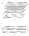
- Figure 5 is an isometric view of another embodiment of the multi-function paper liner as noted in Figure 2 with two insulative layers and a conductive layer;
- Figure 6 is a side view of the multi-function paper liner of Figure 5 ;
- Figure 7 is a side view of another embodiment of the multi-function paper liner as noted in Figure 2 , having two insulative layers and two conductive layers;
- Figure 8 is a side view of another embodiment of the multi-function paper liner as noted in Figure 2 , having an integrated layer and a single insulative layer;
- Figure 9 is a side view of another embodiment of the multi-function paper liner as noted in Figure 2 , having three insulative layers and two conductive layers;
- Figure 10 is a side view of another embodiment of the multi-function paper liner as noted in Figure 2 , having two insulative layers and an integrated layer;
- Figure 11 is an isometric view of another embodiment of the multi-function paper liner as noted in Figure 2 , having a single integrated layer and two silicone layers;
- Figure 12 is a side view of another embodiment of the multi-function paper liner as noted in Figure 2 , having a single integrated layer;
- Figure 13 is a chart of the preferred method of manufacturing a composite material according to the preferred embodiment of the present application for use in forming a composite part through a part lay-up process.
- Multi-function detection liner 501 is one embodiment of a multi-function liner according to the present application. A description of the embodiments is found below.
- a multi-function liner is configured to have one or more layers that allow it the capability of protecting and sealing a prepreg material while also being detected by a plurality of typical production non-destructive inspection methods at various stages of the composite part manufacturing processes.
- the multi-function liner includes at least one of a conductive layer 505 and an insulative layer 503, 503a.
- Liner 501 also illustrates use of a silicone layer 517.
- the multi-function liner is a combination of multiple materials mixed and consolidated by either mechanical or chemical means.
- the multi-function liner is optimized in its material constituents, in the layers laminating order, and in the binding material, so as to meet the liner functional requirements throughout the composite part manufacturing process, including but not limited to, spatial dimensions, flexibility, flatness, mechanical strength, porosity, electrical conductivity, and capacitance to name a few.
- spatial dimensions, flexibility, flatness, mechanical strength, porosity, electrical conductivity, and capacitance to name a few.
- Liner 501 is depicted in Figure 1 to illustrate multiple conductive and insulative layers 503, 505 and serves as a singular embodiment of the multi-function liner. Where multiple layers of each type are used, the layers 91 alternate between types 93: conductive and insulative, as seen with liner 501.
- Each embodiment of the multi-function liner bonds together individual insulative layers to conductive layers.
- the bonding of insulative layers and conductive layers can be done by an adhesive.
- the adhesive layer may be water based or a solvent based pressure sensitive adhesive. Water based adhesive can tend to bubble when subjected to certain levels of increased temperatures. Therefore, it is preferred that a solvent based adhesive is used with the multi-function liner.
- the multi-function liner is configured to provide a number of functions.
- the multi-function liner is configured to releasably couple to a surface of prepreg material 107 (see Figures 3 and 4 ), such as a non-cured composite material or prepreg, so as to protect material 107 from drying out and from sticking prematurely to other objects.
- the multi-function liner is also configured to be detectable to a plurality of non-destruction inspection tests.
- material 107 will be prepreg material.
- Prepreg tends to have a tacky surface which allows the multi-function liner to couple to a surface of material 107 adhesive-free, meaning without the need of additional adhesives.
- a releasable adhesive may be used to secure layer 93 to the surface of material 107 if material 107 is not prepreg. It is to be understood that some methods of forming material 107 include use of the multi-function liner in providing the resin to be infused, therefore both the multi-function liner and material 107 form a composite assembly used to build composite parts.
- Non-destructive inspection tests used to inspect for defects in composite parts during and after the lay-up process are: eddy-current tests, ultrasound tests, and radiograph tests.
- Eddy-current tests may be performed before and after curing of a composite part to isolate defects.
- Ultrasound and radiograph tests are performed after curing of the composite part to isolate defects.
- Eddy-current tests operate with conductive materials and can facilitate detection through ultrasound and radiograph tests.
- One advantage of ultrasound and radiograph testing is the ability to test the entire part more easily than with Eddy-current test which are performed by hand.
- the multi-function liner of the present application combines the attributes of conductive and insulative materials to form a single liner capable of detection through a plurality of non-destructive inspection tests. Such multi-function liner is configured to be applied to a non-cured composite material, or to help form a non-cured composite material, at the point of manufacturing to meet the liner functional requirements throughout the entire composite part manufacturing process.
- a conductive layer is formed from a predominantly conductive material.
- a conductor can be metal of any form 97 including, but not limited to, powder, flakes, solid or braided wires, strips, wire mesh, and foil to name a few.
- the conductivity of a conductive layer is selected and configured to provide adequate eddy current signals and, whenever feasible, to enhance ultrasound reflection properties for detection by a plurality of non-destructive inspection tests.
- a conductive layer is a foil sheet of material having a relatively continuous electrical conductivity.
- Conductive layers preferably contain a metallic material, such as aluminum, to assist in detection from non-destructive inspection tests, such as eddy-current inspection. Aluminum is a relatively inexpensive material.
- the electrical conductivity of the conductive layer may vary depending on the required inspection intervals during a part lay-up process.
- the thickness of the conductive layer is configured to be sized so as to allow for detection at any level in the composite part by non-destructive inspection tests. For example, an aluminum foil when embedded half an inch deep inside a glass/epoxy composite laminate may need to be greater than or equal to 0.0005 inches in thickness to be detected by an eddy current inspection method.
- a conductive layer is not so limited. Other forms or designs of material may be used.
- material 107 may be a carbon fiber reinforced composite material of which the fiber is a conductor.
- an insulative layer is used to separate material 107 from the conductive layer.
- the insulative layer is configured to act as an electrical insulator and exhibit a relatively high dielectric property.
- An insulator can be natural and synthetic materials of any form 97 including, but not limited to, random fiber such as paper; woven fabric such as cloth; and paper or plastic sheets reinforced with unidirectional fiber strands or with woven fabric. Paper is relatively inexpensive as a material which makes it a cost effective selection.
- the insulative layer also permits the multi-function liner to be detectable through ultrasound, as opposed to eddy-current inspection as seen with conductive layers.
- An ultrasound inspection test is a common method for inspecting for embedded defects such as voids and wrinkles in cured composite parts.
- Insulative layers are configured to have a contrasting density to that of the density of material 107 and conductive layers. For example, material 107 and conductive layers may have a higher density than the insulative layer. Likewise, material 107 may be more or less dense than the conductive layers.
- the insulative material, and the multi-function liner as a whole may be detected using an ultrasound test.
- Features, such as the paper weight, surface finish and coating, and porosity, of an insulative layer are tailored to achieve a desired release property and to maximize the ability of the multi-function liner 101 to reflect sound when embedded within a cured part.
- an insulative layer is not limited to paper or other forms 97 of materials. Any other insulative material that falls within the scope and intent of the present application may be used.
- the multi-function liner is also configured to maintain a maximum thermal stability so that the multi-function liner maintains a desired shape when exposed to a variety of temperature ranges. This ability can be seen with the type of adhesive used to bond layers 91, 93 as described previously. Other ways to maintain thermal stability is in the selection of the materials used in layers 93.
- the table of Figure 2 illustrates selected embodiments 95 of the multi-function liner of the present application.
- Each of the embodiments 95 of the multi-function liner are illustrated with an "x" designating the layers 91, 93 included within the embodiment 95. Although only seven layers 91 are shown, it is understood that the multi-function liner may include more than seven layers 91.
- liner 101 is illustrated as an embodiment of the multi-function liner of the present application.
- a lower surface 109 of insulative layer 103 is configured to bond to an upper surface 111 of conductive layer 105 as described above.
- the bonding of insulative layer 103 to conductive layer 105 provides strength to liner 101.
- the minimum thicknesses of conductive layer 105 that is required for detection by non-destructive inspection tests depend on the sensitivities of the equipment used to perform the test. Alone, conductive layer 105 is susceptible to tearing.
- the combination of layers 103 and 105 serve to strengthen liner 101 to prevent tearing.
- the thickness of conductive layer 105 can be optimized to a minimum thickness for detection by non-destructive inspections tests when bonded to insulative layer 103 for increased strength. This allows liner 101 to save material and reduce costs.
- Liner 101 is configured to engage and couple to one or more surfaces of material 107. Since liner 101 has a single insulative layer 103, liner 101 is oriented so as to allow an upper surface 115 of insulative layer 103 to contact material 107 in order to prevent galvanic contamination. However, due to liner 101 having a single insulative layer 103, when liner 101 is used, liner 101 1 is applied to both sides of material 107 to more easily permit transportation of the material 107 and liner 101 assembly, such as with rolled or flat sheets.
- a silicone layer 117 may be applied to surface 115 prior to contacting material 107. Furthermore, a second silicone layer 117 may be applied to a lower surface 113 of conductive layer 105.
- the use of silicone layers 117 is to provide a proper release function of liner 101 from material 107. Some embodiments may use a single silicone layer 117 to perform a proper release function and optionally apply an outer silicone layer 117. By not applying an optional outer silicone layer 117, a user can more easily identify and mark individual sheets or pieces of material 107. For example, a user can write or print on liner 101. Additionally, labels may be applied to, and removed from, liner 101 without causing damage to material 107, insulative layer 103, or conductive layer 105.
- Liner 101 includes one or more silicone layers 117.
- liner 201 is illustrated as another embodiment of the multi-function liner of the present application.
- Liner 201 is substantially similar in form and function to that of liner 101. All the features and characteristics associated with liner 101 are incorporated with respect to liner 201 except as noted herein.
- Liner 201 includes two insulative layers 203, an conductive layer 205, and an optional outer silicone layer 217.
- the term "outer" refers to the surface of the liner furthest from material 107 prior to rolling or stacking the composite assembly.
- Liner 201 further includes a second insulative layer 203 similar to that of insulative layer 103.
- Insulative layer 203 has the same features and functions of insulative layer 103.
- Insulative layers 203 are configured to be bonded to opposing surfaces of conductive layer 205.
- the adhesive used is similar to that of the adhesive used in liner 101.
- Insulative layers 203 are configured to be coupled to a surface of material 107.
- liner 201 may optionally include an outer silicone layer 217.
- liner 201 has two insulative layers 203.
- the use of liner 201 having two insulative layers 203 permits the use of a single liner to be used with material 107 when rolled or stacked.
- both outer surfaces of liner 201 may contact material 107 without concern for galvanic contamination. Therefore, liner 201 allows for use of a single liner 201 and for the material 107 and liner 201 assembly to be rolled or layered for transportation and/or storage.
- a second insulative layer 203 also serves to further strengthen liner 201. Additionally, liner 201 is able to further optimize the size, features, and characteristics of the individual layers 203 and 205 to reduce costs, optimize resources, and increase performance and detection.
- liners 301, 401, 501, 601, 701, and 801 are illustrated as other embodiments of the multi-function liner of the present application.
- the form and function of the conductive layers, insulative layers, and silicone layers are similar to that as described with respect to Figures 3-6 .
- two conductive layers 305 and two insulative layers 303 are used with a liner 301.
- the layers 303, 303a, and 305 are alternated, so that neighboring layers are not of the same type.
- the limitations of liner 101 as pertaining to needing to use two liners with material 107 apply equally here with liner 301 due to an outer most layer being a conductive layer 305.
- At least one silicone layer 317 is used.
- liner 401 uses a single insulative layer 403 and an integrated layer 406.
- Insulative layer 403 and integrated layer 406 are bonded together along a surface similar to that of layers 103 and 105 of liner 101.
- Integrated layer 406 is a combination of different materials that form a hybrid material.
- An example of such hybrid materials are metal vapor coated paper, metal vapor coated fiber strands, or fabric.
- Integrated layer 406 is configured to replace and/or be a combination of one insulative layer and two conductive layers. It is understood that other embodiments of integrated layer 406 may included more or less insulated and/or conductive layers (see Figures 10-12 ).
- liner 501 includes three insulative layers 503, 503a and two conductive layers 505 along with at least one silicone layer 517. As noted previously, the layers 503, 503a, and 505 are alternated, so that neighboring layers are not of the same type.
- the limitations of liner 201 as pertaining to the orientation of and the number of liners used with material 107 apply equally here with liner 501 due to an outer most layer being an insulative layer 505.
- liner 501 An additional benefit of liner 501 is the sandwiching effect of conductive layers 505 on opposing surfaces of insulative layer 503a.
- a resin can be applied to a multi-function liner and transferred to the dry fibrous material through a heating process. In so doing, the resin can seep into the pores of the insulative layer and alter the density of that layer thereby making it more difficult to detect through non-destructive inspection tests.
- This seepage of resin into an insulative layer applies limitations on the characteristics of the insulative layer exposed to the resin. Options concerning choices such as porosity, surface finish, and coating may be limited to avoid resin seepage.
- insulative layer 503a located between conductive layers 505, is protected from resin seepage because conductive layers 505 act as a shield. This allows for the sandwiched insulative layer 503a to have different properties from the outer most insulative layers 503 and ultimately allow liner 501 to become more detectable to non-destructive inspection tests. This same advantage is applicable to any insulative layer located between two conductive layers. Alternate embodiments may be configured to have insulative layers 503 and 503a made of different types of material. For example, insulative layer 503 may be a paper and insulative layer 503a a cloth for added porosity and increased physical rupture and tear strength. Liner 301 in Figure 7 also exhibits this characteristic as seen with layer 303a.
- liner 601 includes two insulative layers 603 bonded to opposing surfaces of an integrated layer 606. At least one silicone layer 617 is used. Integrated layer 606 is similar in form and function to that of integrated layer 406 in Figure 8 .
- liner 701 includes an integrated layer 706 and at least one silicone layer 717.
- Integrated layer 706 is similar in form and function to that of layer 406 and 606 above. However, integrated layer 706 is configured to replace and/or be a combination of three insulative layers and two conductive layers.
- liner 701 illustrates an embodiment wherein the characteristics and features of both an insulative layer and a conductive layer are integrated into a single layer. In such situations, one layer, integrated layer 706, may be used and yet still allow for detection of the multi-function liner through a plurality of non-destruction inspection methods.
- liner 801 includes an integrated layer 806.
- Integrated layer 806 is similar in form and function to that of layer 706 above.
- liner 801 differs from liner 701 in that silicone layers are not needed because the release function is provided intrinsically by the integrated layer 806.
- any of the preceding insulative layers described within Figures 3-12 can include metallic coating deposited on the layers and conductive fillers mixed within the layers.
- Conductive fillers may include metallic strings, shavings, flakes, wire mesh or metal coated organic fibers to name a few.
- an insulative layer when consisting of a sufficiently large amount of metallic content, can replace a conductive layer because it becomes conductive enough to be detected by an eddy current inspection test, for example.
- other embodiments may include both types of conductive layers within a liner.
- conductive layers may also include a plurality of continuous strings lined in a parallel pattern along an edge of an insulative layer. It is preferred that the strings be spaced relatively equally. The distance between strings may be selected to adjust the density, strength, and detectability of the liner. It is preferred that conductive layers be oriented so as to run the strings along the length of material 107, so as to be predominantly in tension if possible.
- the conductive layer may also be a wire mesh bonded to a surface of an insulative layer.
- the spacing of the grid for conductive layer may be selected to adjust the density, strength, and detectability of the liner to non-destructive inspection tests. Additionally, conductive layers described within this specification are not limited to these specific embodiments described.
- a chart 950 of the method of manufacturing a composite part is illustrated.
- a prepreg material and a multi-function liner are provided 951.
- the multi-function liner has insulative and conductive properties found within one or more layers sufficient to make the multi-function liner detectable to a plurality of non-destructive inspection tests.
- the liner is releasably coupled 952 to the prepreg material to form a multi-function composite material assembly. Combining of the multi-function liner and prepreg material occurs during manufacturing of the prepreg material.
- the thicknesses and types of the layers Prior to coupling the prepreg material and the multi- function liner together, the thicknesses and types of the layers are selectively sized and configured to permit detection of the liner at any level within the composite part through the plurality of non-destructive inspection tests.
- the layers may be configured as described previously in Figures 3-12 .
- the liner is retained 953 on the prepreg material from manufacturing, transportation, cutting, and preparation of the material until the prepreg is layered.
- the sheet of prepreg and the liner Prior to layering, are cut 954 to generate a composite cutout ply having a selectively shaped pattern.
- the cutout ply is layered 955 to build a laminated composite part formed from a plurality of composite cutouts plies.
- the liner is removed from the cutout ply prior to layering.
- a non-destructive inspection test is performed on the composite part during and after lay-up to detect any residue portions of the liner remaining between the layers.
- the current application has many advantages over the prior art including the following: (1) reduced cost of manufacturing a composite part by not having to replace the liner; (2) a liner that is releasably bonded to the composite material and is detectable through a plurality of non-destructive inspection tests; (3) prevent galvanic contamination; (4) a stronger liner that is less susceptible to tearing when handled; and (5) a liner that is applied at the point of manufacturing of the prepreg material and provides proper liner functions throughout the lay-up process.
Landscapes
- Engineering & Computer Science (AREA)
- Mechanical Engineering (AREA)
- Chemical & Material Sciences (AREA)
- Composite Materials (AREA)
- Laminated Bodies (AREA)
Abstract
Description
- The present application relates generally to the manufacturing of composite materials and composite parts and, more particularly, to a multi-function detection liner applied to the composite material.
- High performance fiber reinforced composite materials such as those used in space and aerospace applications are manufactured by impregnating dry fibrous material forms, such as unidirectional fibers or woven fabrics, with uncured resins. A resin impregnated fibrous material is also called a prepreg material or a prepreg. A composite part may be laid-up or formed using an automated fiber material placement process, but may also be laid-up by hand. The process includes layering isolated layers of prepreg material to build composite parts of assorted shapes and sizes. This process permits the construction of almost limitless different shaped and sized parts.
- Conventional prepreg manufacturing typically involves one of several different resin impregnation processes. A resin can be applied to a conventional paper liner and transferred to the dry fibrous material or applied directly to the dry fibrous material. The resin is impregnated within the dry fibrous material by applying a heating process to melt and infuse the resin. The heating process may include temperatures of around 200 degrees Fahrenheit or more. Prior to shipping, a portion of the conventional liner is removed. In either situation above, the manufacturing of a laid-up composite part generally includes the application of a conventional paper liner to one or more sides of the prepreg material capable of withstanding the resin infusion pressure at elevated temperatures.
- The conventional liner has many disadvantages. A paper liner is often used in prepreg manufacturing processes because paper, when properly selected or engineered, can withstand the heat and pressure exerted by resin impregnation and consolidation, and it often costs less than other material alternatives. However, conventional paper liners have disadvantages. When unintentionally left on a prepreg during layup of the part, the paper liner cannot easily be detected by typical production non-destructive inspection methods, such as Eddy-current, ultrasound, and radiograph. Retention of any portion of the liner between layers can have negative implications. If a liner is found within a composite part, the material would typically need to be reworked or scrapped, thereby resulting negatively in any delivery schedules. Additionally, the composite part could be weakened at the location of the residual liner which may lead to failure of the part while in use.
- Due to this disadvantage, paper liners on the prepreg, as received from the material supplier, are typically removed and replaced with two metalized plastic liners, one on each side of the prepreg. These metalized plastic liners are generally detectable by Eddy-current methods but can be difficult to be detected by ultrasound methods, and may not be detected by the radiograph method. It is possible that liners, even though detectable by one method, may not be detected for various reasons, for example, liner size, process protocol, and others. Therefore, it is important that a liner, if embedded in a cured part, can be detected by a plurality of different production non-destructive inspection methods. Replacing paper liners with the metalized plastic liners consists of approximately 40 percent of the total time spent in converting prepreg from an as-received good to finished cut plies ready for layup.
- Another disadvantage of conventional liners includes a relative susceptibility to tearing due to a lack of strength in the liner and an inability to withstand the heating process to infuse the resin within the dry fibrous material. A stronger and more detectable liner is needed. A liner capable of meeting the functions of the traditional liner while also being detected by typical production non-destructive inspection methods at various stages of a part manufacturing processes is desired.
- Although great strides have been made in liners for prepreg materials, considerable shortcomings remain.
- The novel features believed characteristic of the application are set forth in the appended claims. However, the application itself, as well as a preferred mode of use, and further objectives and advantages thereof, will best be understood by reference to the following detailed description when read in conjunction with the accompanying drawings, wherein:
-
Figure 1 is an enlarged side view of a single embodiment of a multi-function liner according to the present application having multiple insulative and conductive layers; -
Figure 2 is a table illustrating features and characteristics of selected embodiments of the multi-function liner according to the present application; -
Figure 3 is an isometric view of one embodiment of the multi-function paper liner as noted inFigure 2 , having a single insulative layer and a single conductive layer; -
Figure 4 is a side view of the multi-function paper liner ofFigure 3 ; -
Figure 5 is an isometric view of another embodiment of the multi-function paper liner as noted inFigure 2 with two insulative layers and a conductive layer; -
Figure 6 is a side view of the multi-function paper liner ofFigure 5 ; -
Figure 7 is a side view of another embodiment of the multi-function paper liner as noted inFigure 2 , having two insulative layers and two conductive layers; -
Figure 8 is a side view of another embodiment of the multi-function paper liner as noted inFigure 2 , having an integrated layer and a single insulative layer; -
Figure 9 is a side view of another embodiment of the multi-function paper liner as noted inFigure 2 , having three insulative layers and two conductive layers; -
Figure 10 is a side view of another embodiment of the multi-function paper liner as noted inFigure 2 , having two insulative layers and an integrated layer; -
Figure 11 is an isometric view of another embodiment of the multi-function paper liner as noted inFigure 2 , having a single integrated layer and two silicone layers; -
Figure 12 is a side view of another embodiment of the multi-function paper liner as noted inFigure 2 , having a single integrated layer; and -
Figure 13 is a chart of the preferred method of manufacturing a composite material according to the preferred embodiment of the present application for use in forming a composite part through a part lay-up process. - While the system and method of the present application is susceptible to various modifications and alternative forms, specific embodiments thereof have been shown by way of example in the drawings and are herein described in detail. It should be understood, however, that the description herein of specific embodiments is not intended to limit the application to the particular embodiment disclosed, but on the contrary, the intention is to cover all modifications, equivalents, and alternatives falling within the spirit and scope of the process of the present application as defined by the appended claims.
- Illustrative embodiments of the preferred embodiment are described below. In the interest of clarity, not all features of an actual implementation are described in this specification. It will of course be appreciated that in the development of any such actual embodiment, numerous implementation-specific decisions must be made to achieve the developer's specific goals, such as compliance with system-related and business-related constraints, which will vary from one implementation to another. Moreover, it will be appreciated that such a development effort might be complex and time-consuming but would nevertheless be a routine undertaking for those of ordinary skill in the art having the benefit of this disclosure.
- In the specification, reference may be made to the spatial relationships between various components and to the spatial orientation of various aspects of components as the devices are depicted in the attached drawings. However, as will be recognized by those skilled in the art after a complete reading of the present application, the devices, members, apparatuses, etc. described herein may be positioned in any desired orientation. Thus, the use of terms to describe a spatial relationship between various components or to describe the spatial orientation of aspects of such components should be understood to describe a relative relationship between the components or a spatial orientation of aspects of such components, respectively, as the device described herein may be oriented in any desired direction.
- Referring now to
Figure 1 in the drawings, amulti-function liner 501 is illustrated.Multi-function detection liner 501 is one embodiment of a multi-function liner according to the present application. A description of the embodiments is found below. A multi-function liner is configured to have one or more layers that allow it the capability of protecting and sealing a prepreg material while also being detected by a plurality of typical production non-destructive inspection methods at various stages of the composite part manufacturing processes. As such, the multi-function liner includes at least one of aconductive layer 505 and aninsulative layer silicone layer 517. The multi-function liner is a combination of multiple materials mixed and consolidated by either mechanical or chemical means. The multi-function liner is optimized in its material constituents, in the layers laminating order, and in the binding material, so as to meet the liner functional requirements throughout the composite part manufacturing process, including but not limited to, spatial dimensions, flexibility, flatness, mechanical strength, porosity, electrical conductivity, and capacitance to name a few. Although illustrated and described as having discrete and/or separate conductive and insulative layers, it is understood that some alternative embodiments combine and/or integrate the properties of conducting and insulative layers into a single layer. - Referring now also to
Figure 2 in the drawings, a table 90 is illustrated that depicts a selection of thevarious embodiments 95 of the multi-function liner.Liner 501 is depicted inFigure 1 to illustrate multiple conductive andinsulative layers layers 91 alternate between types 93: conductive and insulative, as seen withliner 501. - Each embodiment of the multi-function liner bonds together individual insulative layers to conductive layers. The bonding of insulative layers and conductive layers can be done by an adhesive. The adhesive layer may be water based or a solvent based pressure sensitive adhesive. Water based adhesive can tend to bubble when subjected to certain levels of increased temperatures. Therefore, it is preferred that a solvent based adhesive is used with the multi-function liner.
- The multi-function liner is configured to provide a number of functions. For example, the multi-function liner is configured to releasably couple to a surface of prepreg material 107 (see
Figures 3 and 4 ), such as a non-cured composite material or prepreg, so as to protect material 107 from drying out and from sticking prematurely to other objects. Furthermore, the multi-function liner is also configured to be detectable to a plurality of non-destruction inspection tests. Although the multi-function liner is being described withmaterial 107, it is understood that the multi-function liner is not so limited may be used with other materials. For purposes in this application,material 107 will be prepreg material. - Prepreg tends to have a tacky surface which allows the multi-function liner to couple to a surface of
material 107 adhesive-free, meaning without the need of additional adhesives. However, a releasable adhesive may be used to securelayer 93 to the surface ofmaterial 107 ifmaterial 107 is not prepreg. It is to be understood that some methods of formingmaterial 107 include use of the multi-function liner in providing the resin to be infused, therefore both the multi-function liner andmaterial 107 form a composite assembly used to build composite parts. - Non-destructive inspection tests used to inspect for defects in composite parts during and after the lay-up process are: eddy-current tests, ultrasound tests, and radiograph tests. Eddy-current tests may be performed before and after curing of a composite part to isolate defects. Ultrasound and radiograph tests are performed after curing of the composite part to isolate defects. Eddy-current tests operate with conductive materials and can facilitate detection through ultrasound and radiograph tests. One advantage of ultrasound and radiograph testing is the ability to test the entire part more easily than with Eddy-current test which are performed by hand. The multi-function liner of the present application combines the attributes of conductive and insulative materials to form a single liner capable of detection through a plurality of non-destructive inspection tests. Such multi-function liner is configured to be applied to a non-cured composite material, or to help form a non-cured composite material, at the point of manufacturing to meet the liner functional requirements throughout the entire composite part manufacturing process.
- A conductive layer is formed from a predominantly conductive material. A conductor can be metal of any
form 97 including, but not limited to, powder, flakes, solid or braided wires, strips, wire mesh, and foil to name a few. The conductivity of a conductive layer is selected and configured to provide adequate eddy current signals and, whenever feasible, to enhance ultrasound reflection properties for detection by a plurality of non-destructive inspection tests. A conductive layer is a foil sheet of material having a relatively continuous electrical conductivity. Conductive layers preferably contain a metallic material, such as aluminum, to assist in detection from non-destructive inspection tests, such as eddy-current inspection. Aluminum is a relatively inexpensive material. The electrical conductivity of the conductive layer may vary depending on the required inspection intervals during a part lay-up process. The thickness of the conductive layer is configured to be sized so as to allow for detection at any level in the composite part by non-destructive inspection tests. For example, an aluminum foil when embedded half an inch deep inside a glass/epoxy composite laminate may need to be greater than or equal to 0.0005 inches in thickness to be detected by an eddy current inspection method. Although described as a foil sheet, a conductive layer is not so limited. Other forms or designs of material may be used. - Metallic materials, such as those used with the conductive layer tend to be susceptible to galvanic contamination when interacting with other electrically conductive materials. For example,
material 107 may be a carbon fiber reinforced composite material of which the fiber is a conductor. In order to prevent galvanic contamination, an insulative layer is used toseparate material 107 from the conductive layer. The insulative layer is configured to act as an electrical insulator and exhibit a relatively high dielectric property. An insulator can be natural and synthetic materials of anyform 97 including, but not limited to, random fiber such as paper; woven fabric such as cloth; and paper or plastic sheets reinforced with unidirectional fiber strands or with woven fabric. Paper is relatively inexpensive as a material which makes it a cost effective selection. Although an insulative layer has been described as separating a conductive layer frommaterial 107, wherematerial 107 is composed of a material, such as glass, where galvanic contamination is not of concern, the conductive layer may contactmaterial 107. - The insulative layer also permits the multi-function liner to be detectable through ultrasound, as opposed to eddy-current inspection as seen with conductive layers. An ultrasound inspection test is a common method for inspecting for embedded defects such as voids and wrinkles in cured composite parts. Insulative layers are configured to have a contrasting density to that of the density of
material 107 and conductive layers. For example,material 107 and conductive layers may have a higher density than the insulative layer. Likewise,material 107 may be more or less dense than the conductive layers. By having a contrasting density to both the conductive layer andmaterial 107, the insulative material, and the multi-function liner as a whole, may be detected using an ultrasound test. Features, such as the paper weight, surface finish and coating, and porosity, of an insulative layer are tailored to achieve a desired release property and to maximize the ability of themulti-function liner 101 to reflect sound when embedded within a cured part. - By configuring the insulative layer to have a contrasting density to that of the conductive layer, ultrasound and radiograph tests may also be used to detect residual portions of the multi-function liner of the present application. Although described as a paper based material, an insulative layer is not limited to paper or
other forms 97 of materials. Any other insulative material that falls within the scope and intent of the present application may be used. - The multi-function liner is also configured to maintain a maximum thermal stability so that the multi-function liner maintains a desired shape when exposed to a variety of temperature ranges. This ability can be seen with the type of adhesive used to
bond layers layers 93. - The table of
Figure 2 illustrates selectedembodiments 95 of the multi-function liner of the present application. Each of theembodiments 95 of the multi-function liner are illustrated with an "x" designating thelayers embodiment 95. Although only sevenlayers 91 are shown, it is understood that the multi-function liner may include more than sevenlayers 91. - Referring now also to
Figures 3 and 4 in the drawings,liner 101 is illustrated as an embodiment of the multi-function liner of the present application. Alower surface 109 ofinsulative layer 103 is configured to bond to anupper surface 111 ofconductive layer 105 as described above. By bondinginsulative layer 103 toconductive layer 105, the strength ofliner 101 as a whole is stronger than theindividual layers insulative layer 103 toconductive layer 105 provides strength toliner 101. The minimum thicknesses ofconductive layer 105 that is required for detection by non-destructive inspection tests depend on the sensitivities of the equipment used to perform the test. Alone,conductive layer 105 is susceptible to tearing. However, the combination oflayers liner 101 to prevent tearing. Furthermore, the thickness ofconductive layer 105 can be optimized to a minimum thickness for detection by non-destructive inspections tests when bonded toinsulative layer 103 for increased strength. This allowsliner 101 to save material and reduce costs. -
Liner 101 is configured to engage and couple to one or more surfaces ofmaterial 107. Sinceliner 101 has asingle insulative layer 103,liner 101 is oriented so as to allow anupper surface 115 ofinsulative layer 103 to contactmaterial 107 in order to prevent galvanic contamination. However, due toliner 101 having asingle insulative layer 103, whenliner 101 is used,liner 101 1 is applied to both sides ofmaterial 107 to more easily permit transportation of thematerial 107 andliner 101 assembly, such as with rolled or flat sheets. - As seen in
Figure 4 , asilicone layer 117 may be applied tosurface 115 prior to contactingmaterial 107. Furthermore, asecond silicone layer 117 may be applied to alower surface 113 ofconductive layer 105. The use of silicone layers 117 is to provide a proper release function ofliner 101 frommaterial 107. Some embodiments may use asingle silicone layer 117 to perform a proper release function and optionally apply anouter silicone layer 117. By not applying an optionalouter silicone layer 117, a user can more easily identify and mark individual sheets or pieces ofmaterial 107. For example, a user can write or print onliner 101. Additionally, labels may be applied to, and removed from,liner 101 without causing damage tomaterial 107,insulative layer 103, orconductive layer 105.Liner 101 includes one or more silicone layers 117. - Referring now also to
Figures 5 and 6 in the drawings,liner 201 is illustrated as another embodiment of the multi-function liner of the present application.Liner 201 is substantially similar in form and function to that ofliner 101. All the features and characteristics associated withliner 101 are incorporated with respect toliner 201 except as noted herein.Liner 201 includes twoinsulative layers 203, anconductive layer 205, and an optionalouter silicone layer 217. The term "outer" refers to the surface of the liner furthest frommaterial 107 prior to rolling or stacking the composite assembly. -
Liner 201 further includes asecond insulative layer 203 similar to that ofinsulative layer 103.Insulative layer 203 has the same features and functions ofinsulative layer 103. Insulative layers 203 are configured to be bonded to opposing surfaces ofconductive layer 205. The adhesive used is similar to that of the adhesive used inliner 101. Insulative layers 203 are configured to be coupled to a surface ofmaterial 107. As withliner 101,liner 201 may optionally include anouter silicone layer 217. - The inclusion of two
insulative layers 203 reduces the risk of galvanic contamination. Furthermore, the use ofliner 201 having twoinsulative layers 203, permits the use of a single liner to be used withmaterial 107 when rolled or stacked. In this respect, both outer surfaces ofliner 201 may contactmaterial 107 without concern for galvanic contamination. Therefore,liner 201 allows for use of asingle liner 201 and for thematerial 107 andliner 201 assembly to be rolled or layered for transportation and/or storage. - The addition of a
second insulative layer 203 also serves to further strengthenliner 201. Additionally,liner 201 is able to further optimize the size, features, and characteristics of theindividual layers - Referring now also to
Figures 7-12 in the drawings,liners Figures 3-6 . - With respect to
Figure 7 , twoconductive layers 305 and twoinsulative layers 303 are used with aliner 301. As noted previously, thelayers liner 101 as pertaining to needing to use two liners withmaterial 107 apply equally here withliner 301 due to an outer most layer being aconductive layer 305. At least onesilicone layer 317 is used. - In particular to
Figure 8 ,liner 401 uses asingle insulative layer 403 and anintegrated layer 406.Insulative layer 403 andintegrated layer 406 are bonded together along a surface similar to that oflayers liner 101.Integrated layer 406 is a combination of different materials that form a hybrid material. An example of such hybrid materials are metal vapor coated paper, metal vapor coated fiber strands, or fabric.Integrated layer 406 is configured to replace and/or be a combination of one insulative layer and two conductive layers. It is understood that other embodiments ofintegrated layer 406 may included more or less insulated and/or conductive layers (seeFigures 10-12 ). - Depending on the conductivity characteristics of
integrated layer 406, the same limitations as seen withliner 101 concerning the orientation of the liner and the number of liners needed to be used withmaterial 107 may apply. Concerns regarding galvanic contamination may be a factor used to determine which layers 403, 406 may contactmaterial 107 and the number ofliners 401 used withmaterial 107. At least onesilicone layer 417 is used. - In particular to
Figure 9 ,liner 501 includes threeinsulative layers conductive layers 505 along with at least onesilicone layer 517. As noted previously, thelayers liner 201 as pertaining to the orientation of and the number of liners used withmaterial 107 apply equally here withliner 501 due to an outer most layer being aninsulative layer 505. - An additional benefit of
liner 501 is the sandwiching effect ofconductive layers 505 on opposing surfaces ofinsulative layer 503a. During the process of applying the multi-function liner tomaterial 107, a resin can be applied to a multi-function liner and transferred to the dry fibrous material through a heating process. In so doing, the resin can seep into the pores of the insulative layer and alter the density of that layer thereby making it more difficult to detect through non-destructive inspection tests. This seepage of resin into an insulative layer applies limitations on the characteristics of the insulative layer exposed to the resin. Options concerning choices such as porosity, surface finish, and coating may be limited to avoid resin seepage. However,insulative layer 503a, located betweenconductive layers 505, is protected from resin seepage becauseconductive layers 505 act as a shield. This allows for the sandwichedinsulative layer 503a to have different properties from the outer mostinsulative layers 503 and ultimately allowliner 501 to become more detectable to non-destructive inspection tests. This same advantage is applicable to any insulative layer located between two conductive layers. Alternate embodiments may be configured to haveinsulative layers insulative layer 503 may be a paper andinsulative layer 503a a cloth for added porosity and increased physical rupture and tear strength.Liner 301 inFigure 7 also exhibits this characteristic as seen withlayer 303a. - In particular to
Figure 10 ,liner 601 includes twoinsulative layers 603 bonded to opposing surfaces of anintegrated layer 606. At least onesilicone layer 617 is used.Integrated layer 606 is similar in form and function to that ofintegrated layer 406 inFigure 8 . - In particular to
Figure 11 ,liner 701 includes anintegrated layer 706 and at least onesilicone layer 717.Integrated layer 706 is similar in form and function to that oflayer integrated layer 706 is configured to replace and/or be a combination of three insulative layers and two conductive layers. - Although a multi-function liner has been described as having a conductive layer and an insulative layer,
liner 701 illustrates an embodiment wherein the characteristics and features of both an insulative layer and a conductive layer are integrated into a single layer. In such situations, one layer, integratedlayer 706, may be used and yet still allow for detection of the multi-function liner through a plurality of non-destruction inspection methods. - In particular to
Figure 12 ,liner 801 includes anintegrated layer 806.Integrated layer 806 is similar in form and function to that oflayer 706 above. However,liner 801 differs fromliner 701 in that silicone layers are not needed because the release function is provided intrinsically by theintegrated layer 806. - It is understood that any of the preceding insulative layers described within
Figures 3-12 can include metallic coating deposited on the layers and conductive fillers mixed within the layers. Conductive fillers may include metallic strings, shavings, flakes, wire mesh or metal coated organic fibers to name a few. In such an embodiment, an insulative layer, when consisting of a sufficiently large amount of metallic content, can replace a conductive layer because it becomes conductive enough to be detected by an eddy current inspection test, for example. However, other embodiments may include both types of conductive layers within a liner. - Furthermore, although the preceding conductive layers within
Figures 3-12 have been described as a sheet having a relatively uniform thickness, it is understood that conductive layers may also include a plurality of continuous strings lined in a parallel pattern along an edge of an insulative layer. It is preferred that the strings be spaced relatively equally. The distance between strings may be selected to adjust the density, strength, and detectability of the liner. It is preferred that conductive layers be oriented so as to run the strings along the length ofmaterial 107, so as to be predominantly in tension if possible. - The conductive layer may also be a wire mesh bonded to a surface of an insulative layer. The spacing of the grid for conductive layer may be selected to adjust the density, strength, and detectability of the liner to non-destructive inspection tests. Additionally, conductive layers described within this specification are not limited to these specific embodiments described.
- Referring now also to
Figure 13 in the drawings, achart 950 of the method of manufacturing a composite part is illustrated. A prepreg material and a multi-function liner are provided 951. The multi-function liner has insulative and conductive properties found within one or more layers sufficient to make the multi-function liner detectable to a plurality of non-destructive inspection tests. The liner is releasably coupled 952 to the prepreg material to form a multi-function composite material assembly. Combining of the multi-function liner and prepreg material occurs during manufacturing of the prepreg material. Prior to coupling the prepreg material and the multi- function liner together, the thicknesses and types of the layers are selectively sized and configured to permit detection of the liner at any level within the composite part through the plurality of non-destructive inspection tests. For example, the layers may be configured as described previously inFigures 3-12 . - The liner is retained 953 on the prepreg material from manufacturing, transportation, cutting, and preparation of the material until the prepreg is layered. Prior to layering, the sheet of prepreg and the liner are cut 954 to generate a composite cutout ply having a selectively shaped pattern. The cutout ply is layered 955 to build a laminated composite part formed from a plurality of composite cutouts plies. The liner is removed from the cutout ply prior to layering. A non-destructive inspection test is performed on the composite part during and after lay-up to detect any residue portions of the liner remaining between the layers.
- The current application has many advantages over the prior art including the following: (1) reduced cost of manufacturing a composite part by not having to replace the liner; (2) a liner that is releasably bonded to the composite material and is detectable through a plurality of non-destructive inspection tests; (3) prevent galvanic contamination; (4) a stronger liner that is less susceptible to tearing when handled; and (5) a liner that is applied at the point of manufacturing of the prepreg material and provides proper liner functions throughout the lay-up process.
- The particular embodiments disclosed above are illustrative only, as the application may be modified and practiced in different but equivalent manners apparent to those skilled in the art having the benefit of the teachings herein. It is therefore evident that the particular embodiments disclosed above may be altered or modified, and all such variations are considered within the scope and spirit of the application. Accordingly, the protection sought herein is as set forth in the description. It is apparent that an application with significant advantages has been described and illustrated. Although the present application is shown in a limited number of forms, it is not limited to just these forms, but is amenable to various changes and modifications without departing from the spirit thereof.
Claims (15)
- A multi-function detection liner for a non-cured composite material for use in the lay-up of a composite part, comprising:a first insulative layer having a density in contrast to that of the non-cured composite material, such that the first insulative layer is detectable by ultrasound within the composite part; anda first conductive layer bonded to the first insulative layer and configured to provide an eddy current signal and to enhance ultrasound attenuation of the detection liner within the composite part;wherein the detection liner is releasable from a surface of the non-cured composite material during the lay-up process.
- The multi-function detection liner of claim 1, wherein the first insulative layer and the first conductive layer are configured to be detected by a plurality non-destructive inspection methods.
- The multi-function detection liner of claim 1 or of claim 2, wherein the first insulative layer is applied to the surface of the non-cured composite material.
- The multi-function detection liner of claim 1 or of claim 2 or of claim 3, wherein the first conductive layer is at least one of a sheet, a string, and a mesh.
- The multi-function detection liner of claim 1 or of any of claims 2 to 4, further comprising:a second insulative layer bonded to a lower surface of the first conductive layer opposite the first insulative layer, the second insulative layer configured to have a density varied from that of the non-cured composite material and the composite part.
- The multi-function detection liner of claim 5, further comprising:a second conductive layer configured to provide additional strength, the second conductive layer being bonded to the first insulative layer and the first conductive layer.
- The multi-function detection liner of claim 6, wherein:-(I) the layers are alternated within the detection liner are alternated between insulative layers and conductive layers; or(II) the first conductive layer and the second conductive layer are bonded to opposing surfaces of the second insulative layer, and optionally or preferably wherein the features of the second insulative layer is different from the features of the first insulative layer, so as to increase detection through non-destructive inspection tests.
- The multi-function detection liner of claim 1, further comprising:an integrated layer having properties and features of a conductive layer and an insulative layer.
- The multi-function detection liner of claim 1, or of any of claims 2 to 8, wherein the first insulative layer includes conductive fillers such as a metallic fiber and a metal coated non-conductive fiber.
- The multi-function detection liner of claim 1, or of any of claims 2 to 9, wherein the detection liner is capable of withstanding elevated temperatures above 200 degrees Fahrenheit.
- A method of manufacturing a composite part using a lay-up process, comprising:providing a non-cured composite material;providing a first multi-function detection liner having a first outside layer and an conductive layer bonded together configured to be detected during a non-destructive inspection test;releasably bonding the first detection liner to a surface of the non-cured composite material to form a sheet;retaining the first detection liner bonded to the surface of the non-cured composite material until the non-cured composite material is layered, the first detection liner is configured to be detected by a plurality of non-destructive inspection tests;cutting the sheet to generate at least one composite cutout ply having a selectively shaped pattern; andlayering the composite cutout ply to build a laminated composite part formed from a plurality of composite cutouts plies, the laminated composite part having the detection liner removed prior to layering.
- The method of claim 11, wherein the first detection liner is configured to prevent galvanic contamination of the conductive layer with another material.
- The method of claim 12, further comprising:performing a non-destructive inspection on the laminated composite part to detect the presence of the detection liner between the plurality of layers of the composite cutouts.
- The method of claim 13, wherein the non-destructive inspection is performed by using an ultrasound method to detect changes in sound reflection due to the first detection liner, or by using an eddy-current method to detect presence of metal in the first detection liner, or
by using a radiograph method to detect changes in material density due to the first detection liner. - The method of claim 11, or of any of claims 12 to 14, further comprising:(i) releasably bonding a second multi-function detection liner to an opposing surface of the non-cured composite material from that of the first multi-function detection liner, and/or(ii) the method wherein at least one of the thickness, density, and electrical conductivity of the conductive and insulative layers are determined prior to bonding the first detection liner to the composite material, such that the first detection liner is sized to permit detection at any level within the composite part by the non-destructive inspection test.
Applications Claiming Priority (1)
| Application Number | Priority Date | Filing Date | Title |
|---|---|---|---|
| US13/455,855 US9205605B2 (en) | 2012-04-25 | 2012-04-25 | Multi-function detection liner for manufacturing of composites |
Publications (2)
| Publication Number | Publication Date |
|---|---|
| EP2666616A1 true EP2666616A1 (en) | 2013-11-27 |
| EP2666616B1 EP2666616B1 (en) | 2014-08-13 |
Family
ID=46640540
Family Applications (1)
| Application Number | Title | Priority Date | Filing Date |
|---|---|---|---|
| EP12174243.1A Active EP2666616B1 (en) | 2012-04-25 | 2012-06-28 | composite material assembly comprising a release liner with multi-functional detection properties and method for manufacturing of composites using same |
Country Status (3)
| Country | Link |
|---|---|
| US (1) | US9205605B2 (en) |
| EP (1) | EP2666616B1 (en) |
| CA (1) | CA2805949C (en) |
Cited By (1)
| Publication number | Priority date | Publication date | Assignee | Title |
|---|---|---|---|---|
| WO2016001237A1 (en) * | 2014-07-03 | 2016-01-07 | Wacker Chemie Ag | Preparation of multilayer structural composites prepared using consolidation liners of high parting force |
Families Citing this family (5)
| Publication number | Priority date | Publication date | Assignee | Title |
|---|---|---|---|---|
| FR3027839B1 (en) * | 2014-10-31 | 2017-09-08 | Plastic Omnium Cie | PLASTIC SHEET PREFORMING SYSTEM WITH SEQUENTIALLY ACTUATING PLATING MEANS |
| DE102018101453A1 (en) * | 2018-01-23 | 2019-07-25 | Borgwarner Ludwigsburg Gmbh | Heating device and method for producing a heating rod |
| EP3533592B1 (en) * | 2018-02-28 | 2022-11-16 | AIRBUS HELICOPTERS DEUTSCHLAND GmbH | Composite materials enabling non-destructive testing |
| CN113799418B (en) * | 2021-08-23 | 2022-10-21 | 厦门大学 | Preparation method of intelligent composite material bolt, composite material bolt and use method |
| CN113635817A (en) * | 2021-08-24 | 2021-11-12 | 艾福迈汽车系统(上海)有限公司 | Seat capacitive sensor based on conductive fabric and measuring method |
Citations (3)
| Publication number | Priority date | Publication date | Assignee | Title |
|---|---|---|---|---|
| US20060108056A1 (en) * | 2004-11-24 | 2006-05-25 | The Boeing Company | Method and apparatus for foreign object detection in a composite layer fabrication process |
| US20070166523A1 (en) * | 2006-01-17 | 2007-07-19 | Lintec Corporation | Release film and process for producing the film |
| US20120012382A1 (en) * | 2009-05-13 | 2012-01-19 | Laird Technologies, Inc. | Conductive Films for EMI Shielding Applications |
Family Cites Families (16)
| Publication number | Priority date | Publication date | Assignee | Title |
|---|---|---|---|---|
| US4685987A (en) * | 1983-09-02 | 1987-08-11 | The Bergquist Company | Method of preparing interfacings of heat sinks with electrical devices |
| US5073595A (en) * | 1987-12-23 | 1991-12-17 | Minnesota Mining And Manufacturing Company | Epoxide resin compositions and method |
| TW340967B (en) * | 1996-02-19 | 1998-09-21 | Toray Industries | An adhesive sheet for a semiconductor to connect with a substrate, and adhesive sticking tape for tab, an adhesive sticking tape for wire bonding connection, a substrate for connecting with a semiconductor and a semiconductor device |
| CA2332158C (en) * | 2000-03-07 | 2004-09-14 | Matsushita Electric Industrial Co., Ltd. | Ultrasonic probe |
| US20020182955A1 (en) | 2001-03-29 | 2002-12-05 | Weglewski James T. | Structural bonding tapes and articles containing the same |
| US20030037512A1 (en) | 2001-08-21 | 2003-02-27 | Arnold Finestone | Process for making a self-closing, resealable package |
| US6984427B2 (en) | 2002-01-10 | 2006-01-10 | 3M Innovative Properties Company | Microstructed release liner |
| US20040086551A1 (en) | 2002-10-30 | 2004-05-06 | Miller Kenneth J. | Fentanyl suspension-based silicone adhesive formulations and devices for transdermal delivery of fentanyl |
| US7744991B2 (en) | 2003-05-30 | 2010-06-29 | 3M Innovative Properties Company | Thermally conducting foam interface materials |
| US7468199B2 (en) * | 2004-12-23 | 2008-12-23 | 3M Innovative Properties Company | Adhesive membrane for force switches and sensors |
| JP2006215024A (en) * | 2005-01-04 | 2006-08-17 | Mitsubishi Chem Mkv Co | Composite material for detecting breakage of liner sheet |
| US20070212551A1 (en) * | 2006-03-10 | 2007-09-13 | Andrew Collins | Adhesive composition |
| DE102006035847B4 (en) * | 2006-08-01 | 2009-11-19 | Airbus Deutschland Gmbh | Structural arrangement and method for producing a component for aerospace |
| JP5101919B2 (en) * | 2007-04-09 | 2012-12-19 | 日東電工株式会社 | Double-sided adhesive tape or sheet for printed circuit board and printed circuit board with double-sided adhesive tape |
| JP5541847B2 (en) * | 2008-04-30 | 2014-07-09 | 日東電工株式会社 | Adhesive sheet with release liner |
| CN102047403A (en) * | 2008-06-02 | 2011-05-04 | Nxp股份有限公司 | Electronic device and method of manufacturing an electronic device |
-
2012
- 2012-04-25 US US13/455,855 patent/US9205605B2/en active Active
- 2012-06-28 EP EP12174243.1A patent/EP2666616B1/en active Active
-
2013
- 2013-02-12 CA CA2805949A patent/CA2805949C/en active Active
Patent Citations (3)
| Publication number | Priority date | Publication date | Assignee | Title |
|---|---|---|---|---|
| US20060108056A1 (en) * | 2004-11-24 | 2006-05-25 | The Boeing Company | Method and apparatus for foreign object detection in a composite layer fabrication process |
| US20070166523A1 (en) * | 2006-01-17 | 2007-07-19 | Lintec Corporation | Release film and process for producing the film |
| US20120012382A1 (en) * | 2009-05-13 | 2012-01-19 | Laird Technologies, Inc. | Conductive Films for EMI Shielding Applications |
Cited By (1)
| Publication number | Priority date | Publication date | Assignee | Title |
|---|---|---|---|---|
| WO2016001237A1 (en) * | 2014-07-03 | 2016-01-07 | Wacker Chemie Ag | Preparation of multilayer structural composites prepared using consolidation liners of high parting force |
Also Published As
| Publication number | Publication date |
|---|---|
| US9205605B2 (en) | 2015-12-08 |
| CA2805949A1 (en) | 2013-10-25 |
| CA2805949C (en) | 2015-09-08 |
| US20130283920A1 (en) | 2013-10-31 |
| EP2666616B1 (en) | 2014-08-13 |
Similar Documents
| Publication | Publication Date | Title |
|---|---|---|
| CA2805949C (en) | Multi-function detection liner for manufacturing of composites | |
| US8947847B2 (en) | Methods for forming a structure having a lightning strike protection | |
| CA2824976C (en) | System and method for monitoring bonding integrity | |
| US8709189B2 (en) | Method for fabrication of integrated lightning strike protection material | |
| AU2015213272B2 (en) | Filament network for a composite structure | |
| JP6448628B2 (en) | Composite panel for floor or wall covering parts and method for manufacturing such a panel | |
| EP2103416A2 (en) | Prepreg peel ply for continuously forming composite material | |
| Chilles et al. | Design of an embedded sensor, for improved structural performance | |
| EP3898227A1 (en) | Fiber-reinforced composite layup | |
| US20120298927A1 (en) | Electrically conductive adhesives comprising bucky paper and an adhesive resin | |
| US11559967B2 (en) | Multifunctional surfacing films | |
| KR20210070268A (en) | Cushioning material for hot press and manufacturing method of cushioning material for hot press | |
| CA2008894C (en) | Method for detecting protective layer on composite materials | |
| CA2883719C (en) | Composite structures having bondlines with matched electrical conductivity | |
| EP3014020B1 (en) | Dissipation of static electricity | |
| US10920994B2 (en) | Heated floor panels | |
| Adin | The investigation of effect of adherend thickness on scarf lap joints | |
| CN211178779U (en) | State monitoring integrated composite material structure | |
| JP5571499B2 (en) | Conductive fiber reinforced plastic, method for producing the same, and electromagnetic shielding material using the same | |
| CN111928971B (en) | State monitoring integrated composite material structure | |
| KR20220154253A (en) | Separator member for fuel cell and manufacturing method thereof | |
| CA3064096A1 (en) | Edge damage tolerant heated and unheated composite panels with rotated honeycomb edge pieces |
Legal Events
| Date | Code | Title | Description |
|---|---|---|---|
| PUAI | Public reference made under article 153(3) epc to a published international application that has entered the european phase |
Free format text: ORIGINAL CODE: 0009012 |
|
| 17P | Request for examination filed |
Effective date: 20120726 |
|
| AK | Designated contracting states |
Kind code of ref document: A1 Designated state(s): AL AT BE BG CH CY CZ DE DK EE ES FI FR GB GR HR HU IE IS IT LI LT LU LV MC MK MT NL NO PL PT RO RS SE SI SK SM TR |
|
| AX | Request for extension of the european patent |
Extension state: BA ME |
|
| RIC1 | Information provided on ipc code assigned before grant |
Ipc: B29C 70/54 20060101AFI20140307BHEP Ipc: B29C 33/68 20060101ALI20140307BHEP Ipc: G01N 29/11 20060101ALI20140307BHEP Ipc: G01N 19/08 20060101ALI20140307BHEP Ipc: G01N 27/90 20060101ALI20140307BHEP Ipc: G01N 29/04 20060101ALI20140307BHEP |
|
| GRAP | Despatch of communication of intention to grant a patent |
Free format text: ORIGINAL CODE: EPIDOSNIGR1 |
|
| GRAJ | Information related to disapproval of communication of intention to grant by the applicant or resumption of examination proceedings by the epo deleted |
Free format text: ORIGINAL CODE: EPIDOSDIGR1 |
|
| INTG | Intention to grant announced |
Effective date: 20140507 |
|
| GRAP | Despatch of communication of intention to grant a patent |
Free format text: ORIGINAL CODE: EPIDOSNIGR1 |
|
| GRAS | Grant fee paid |
Free format text: ORIGINAL CODE: EPIDOSNIGR3 |
|
| INTG | Intention to grant announced |
Effective date: 20140610 |
|
| GRAA | (expected) grant |
Free format text: ORIGINAL CODE: 0009210 |
|
| AK | Designated contracting states |
Kind code of ref document: B1 Designated state(s): AL AT BE BG CH CY CZ DE DK EE ES FI FR GB GR HR HU IE IS IT LI LT LU LV MC MK MT NL NO PL PT RO RS SE SI SK SM TR |
|
| REG | Reference to a national code |
Ref country code: GB Ref legal event code: FG4D |
|
| REG | Reference to a national code |
Ref country code: CH Ref legal event code: EP Ref country code: AT Ref legal event code: REF Ref document number: 681938 Country of ref document: AT Kind code of ref document: T Effective date: 20140815 |
|
| REG | Reference to a national code |
Ref country code: IE Ref legal event code: FG4D |
|
| REG | Reference to a national code |
Ref country code: DE Ref legal event code: R096 Ref document number: 602012002717 Country of ref document: DE Effective date: 20140925 |
|
| REG | Reference to a national code |
Ref country code: NL Ref legal event code: VDEP Effective date: 20140813 |
|
| REG | Reference to a national code |
Ref country code: AT Ref legal event code: MK05 Ref document number: 681938 Country of ref document: AT Kind code of ref document: T Effective date: 20140813 |
|
| REG | Reference to a national code |
Ref country code: LT Ref legal event code: MG4D |
|
| PG25 | Lapsed in a contracting state [announced via postgrant information from national office to epo] |
Ref country code: FI Free format text: LAPSE BECAUSE OF FAILURE TO SUBMIT A TRANSLATION OF THE DESCRIPTION OR TO PAY THE FEE WITHIN THE PRESCRIBED TIME-LIMIT Effective date: 20140813 Ref country code: GR Free format text: LAPSE BECAUSE OF FAILURE TO SUBMIT A TRANSLATION OF THE DESCRIPTION OR TO PAY THE FEE WITHIN THE PRESCRIBED TIME-LIMIT Effective date: 20141114 Ref country code: LT Free format text: LAPSE BECAUSE OF FAILURE TO SUBMIT A TRANSLATION OF THE DESCRIPTION OR TO PAY THE FEE WITHIN THE PRESCRIBED TIME-LIMIT Effective date: 20140813 Ref country code: SE Free format text: LAPSE BECAUSE OF FAILURE TO SUBMIT A TRANSLATION OF THE DESCRIPTION OR TO PAY THE FEE WITHIN THE PRESCRIBED TIME-LIMIT Effective date: 20140813 Ref country code: BG Free format text: LAPSE BECAUSE OF FAILURE TO SUBMIT A TRANSLATION OF THE DESCRIPTION OR TO PAY THE FEE WITHIN THE PRESCRIBED TIME-LIMIT Effective date: 20141113 Ref country code: ES Free format text: LAPSE BECAUSE OF FAILURE TO SUBMIT A TRANSLATION OF THE DESCRIPTION OR TO PAY THE FEE WITHIN THE PRESCRIBED TIME-LIMIT Effective date: 20140813 Ref country code: NO Free format text: LAPSE BECAUSE OF FAILURE TO SUBMIT A TRANSLATION OF THE DESCRIPTION OR TO PAY THE FEE WITHIN THE PRESCRIBED TIME-LIMIT Effective date: 20141113 Ref country code: PT Free format text: LAPSE BECAUSE OF FAILURE TO SUBMIT A TRANSLATION OF THE DESCRIPTION OR TO PAY THE FEE WITHIN THE PRESCRIBED TIME-LIMIT Effective date: 20141215 |
|
| PG25 | Lapsed in a contracting state [announced via postgrant information from national office to epo] |
Ref country code: CY Free format text: LAPSE BECAUSE OF FAILURE TO SUBMIT A TRANSLATION OF THE DESCRIPTION OR TO PAY THE FEE WITHIN THE PRESCRIBED TIME-LIMIT Effective date: 20140813 Ref country code: HR Free format text: LAPSE BECAUSE OF FAILURE TO SUBMIT A TRANSLATION OF THE DESCRIPTION OR TO PAY THE FEE WITHIN THE PRESCRIBED TIME-LIMIT Effective date: 20140813 Ref country code: LV Free format text: LAPSE BECAUSE OF FAILURE TO SUBMIT A TRANSLATION OF THE DESCRIPTION OR TO PAY THE FEE WITHIN THE PRESCRIBED TIME-LIMIT Effective date: 20140813 Ref country code: AT Free format text: LAPSE BECAUSE OF FAILURE TO SUBMIT A TRANSLATION OF THE DESCRIPTION OR TO PAY THE FEE WITHIN THE PRESCRIBED TIME-LIMIT Effective date: 20140813 Ref country code: RS Free format text: LAPSE BECAUSE OF FAILURE TO SUBMIT A TRANSLATION OF THE DESCRIPTION OR TO PAY THE FEE WITHIN THE PRESCRIBED TIME-LIMIT Effective date: 20140813 Ref country code: IS Free format text: LAPSE BECAUSE OF FAILURE TO SUBMIT A TRANSLATION OF THE DESCRIPTION OR TO PAY THE FEE WITHIN THE PRESCRIBED TIME-LIMIT Effective date: 20141213 |
|
| PG25 | Lapsed in a contracting state [announced via postgrant information from national office to epo] |
Ref country code: NL Free format text: LAPSE BECAUSE OF FAILURE TO SUBMIT A TRANSLATION OF THE DESCRIPTION OR TO PAY THE FEE WITHIN THE PRESCRIBED TIME-LIMIT Effective date: 20140813 |
|
| PG25 | Lapsed in a contracting state [announced via postgrant information from national office to epo] |
Ref country code: RO Free format text: LAPSE BECAUSE OF FAILURE TO SUBMIT A TRANSLATION OF THE DESCRIPTION OR TO PAY THE FEE WITHIN THE PRESCRIBED TIME-LIMIT Effective date: 20140813 Ref country code: SK Free format text: LAPSE BECAUSE OF FAILURE TO SUBMIT A TRANSLATION OF THE DESCRIPTION OR TO PAY THE FEE WITHIN THE PRESCRIBED TIME-LIMIT Effective date: 20140813 Ref country code: CZ Free format text: LAPSE BECAUSE OF FAILURE TO SUBMIT A TRANSLATION OF THE DESCRIPTION OR TO PAY THE FEE WITHIN THE PRESCRIBED TIME-LIMIT Effective date: 20140813 Ref country code: EE Free format text: LAPSE BECAUSE OF FAILURE TO SUBMIT A TRANSLATION OF THE DESCRIPTION OR TO PAY THE FEE WITHIN THE PRESCRIBED TIME-LIMIT Effective date: 20140813 Ref country code: DK Free format text: LAPSE BECAUSE OF FAILURE TO SUBMIT A TRANSLATION OF THE DESCRIPTION OR TO PAY THE FEE WITHIN THE PRESCRIBED TIME-LIMIT Effective date: 20140813 |
|
| REG | Reference to a national code |
Ref country code: DE Ref legal event code: R097 Ref document number: 602012002717 Country of ref document: DE |
|
| PG25 | Lapsed in a contracting state [announced via postgrant information from national office to epo] |
Ref country code: PL Free format text: LAPSE BECAUSE OF FAILURE TO SUBMIT A TRANSLATION OF THE DESCRIPTION OR TO PAY THE FEE WITHIN THE PRESCRIBED TIME-LIMIT Effective date: 20140813 |
|
| PLBE | No opposition filed within time limit |
Free format text: ORIGINAL CODE: 0009261 |
|
| STAA | Information on the status of an ep patent application or granted ep patent |
Free format text: STATUS: NO OPPOSITION FILED WITHIN TIME LIMIT |
|
| 26N | No opposition filed |
Effective date: 20150515 |
|
| PG25 | Lapsed in a contracting state [announced via postgrant information from national office to epo] |
Ref country code: SI Free format text: LAPSE BECAUSE OF FAILURE TO SUBMIT A TRANSLATION OF THE DESCRIPTION OR TO PAY THE FEE WITHIN THE PRESCRIBED TIME-LIMIT Effective date: 20140813 |
|
| PG25 | Lapsed in a contracting state [announced via postgrant information from national office to epo] |
Ref country code: MC Free format text: LAPSE BECAUSE OF FAILURE TO SUBMIT A TRANSLATION OF THE DESCRIPTION OR TO PAY THE FEE WITHIN THE PRESCRIBED TIME-LIMIT Effective date: 20140813 |
|
| REG | Reference to a national code |
Ref country code: CH Ref legal event code: PL |
|
| PG25 | Lapsed in a contracting state [announced via postgrant information from national office to epo] |
Ref country code: LU Free format text: LAPSE BECAUSE OF FAILURE TO SUBMIT A TRANSLATION OF THE DESCRIPTION OR TO PAY THE FEE WITHIN THE PRESCRIBED TIME-LIMIT Effective date: 20150628 |
|
| REG | Reference to a national code |
Ref country code: IE Ref legal event code: MM4A |
|
| PG25 | Lapsed in a contracting state [announced via postgrant information from national office to epo] |
Ref country code: IE Free format text: LAPSE BECAUSE OF NON-PAYMENT OF DUE FEES Effective date: 20150628 Ref country code: CH Free format text: LAPSE BECAUSE OF NON-PAYMENT OF DUE FEES Effective date: 20150630 Ref country code: LI Free format text: LAPSE BECAUSE OF NON-PAYMENT OF DUE FEES Effective date: 20150630 |
|
| REG | Reference to a national code |
Ref country code: FR Ref legal event code: PLFP Year of fee payment: 5 |
|
| PG25 | Lapsed in a contracting state [announced via postgrant information from national office to epo] |
Ref country code: BE Free format text: LAPSE BECAUSE OF FAILURE TO SUBMIT A TRANSLATION OF THE DESCRIPTION OR TO PAY THE FEE WITHIN THE PRESCRIBED TIME-LIMIT Effective date: 20140813 |
|
| PG25 | Lapsed in a contracting state [announced via postgrant information from national office to epo] |
Ref country code: MT Free format text: LAPSE BECAUSE OF FAILURE TO SUBMIT A TRANSLATION OF THE DESCRIPTION OR TO PAY THE FEE WITHIN THE PRESCRIBED TIME-LIMIT Effective date: 20140813 |
|
| PG25 | Lapsed in a contracting state [announced via postgrant information from national office to epo] |
Ref country code: HU Free format text: LAPSE BECAUSE OF FAILURE TO SUBMIT A TRANSLATION OF THE DESCRIPTION OR TO PAY THE FEE WITHIN THE PRESCRIBED TIME-LIMIT; INVALID AB INITIO Effective date: 20120628 Ref country code: SM Free format text: LAPSE BECAUSE OF FAILURE TO SUBMIT A TRANSLATION OF THE DESCRIPTION OR TO PAY THE FEE WITHIN THE PRESCRIBED TIME-LIMIT Effective date: 20140813 |
|
| REG | Reference to a national code |
Ref country code: FR Ref legal event code: PLFP Year of fee payment: 6 |
|
| PG25 | Lapsed in a contracting state [announced via postgrant information from national office to epo] |
Ref country code: TR Free format text: LAPSE BECAUSE OF FAILURE TO SUBMIT A TRANSLATION OF THE DESCRIPTION OR TO PAY THE FEE WITHIN THE PRESCRIBED TIME-LIMIT Effective date: 20140813 |
|
| REG | Reference to a national code |
Ref country code: FR Ref legal event code: PLFP Year of fee payment: 7 |
|
| PG25 | Lapsed in a contracting state [announced via postgrant information from national office to epo] |
Ref country code: MK Free format text: LAPSE BECAUSE OF FAILURE TO SUBMIT A TRANSLATION OF THE DESCRIPTION OR TO PAY THE FEE WITHIN THE PRESCRIBED TIME-LIMIT Effective date: 20140813 |
|
| PG25 | Lapsed in a contracting state [announced via postgrant information from national office to epo] |
Ref country code: AL Free format text: LAPSE BECAUSE OF FAILURE TO SUBMIT A TRANSLATION OF THE DESCRIPTION OR TO PAY THE FEE WITHIN THE PRESCRIBED TIME-LIMIT Effective date: 20140813 |
|
| P01 | Opt-out of the competence of the unified patent court (upc) registered |
Effective date: 20230602 |
|
| PGFP | Annual fee paid to national office [announced via postgrant information from national office to epo] |
Ref country code: IT Payment date: 20230620 Year of fee payment: 12 |
|
| PGFP | Annual fee paid to national office [announced via postgrant information from national office to epo] |
Ref country code: GB Payment date: 20240627 Year of fee payment: 13 |
|
| PGFP | Annual fee paid to national office [announced via postgrant information from national office to epo] |
Ref country code: DE Payment date: 20240627 Year of fee payment: 13 |
|
| PGFP | Annual fee paid to national office [announced via postgrant information from national office to epo] |
Ref country code: FR Payment date: 20240625 Year of fee payment: 13 |