EP2666537A1 - Membrane separation device - Google Patents
Membrane separation device Download PDFInfo
- Publication number
- EP2666537A1 EP2666537A1 EP12736914.8A EP12736914A EP2666537A1 EP 2666537 A1 EP2666537 A1 EP 2666537A1 EP 12736914 A EP12736914 A EP 12736914A EP 2666537 A1 EP2666537 A1 EP 2666537A1
- Authority
- EP
- European Patent Office
- Prior art keywords
- membrane
- elastic member
- membrane modules
- frame body
- liquid
- Prior art date
- Legal status (The legal status is an assumption and is not a legal conclusion. Google has not performed a legal analysis and makes no representation as to the accuracy of the status listed.)
- Granted
Links
Images



Classifications
-
- C—CHEMISTRY; METALLURGY
- C02—TREATMENT OF WATER, WASTE WATER, SEWAGE, OR SLUDGE
- C02F—TREATMENT OF WATER, WASTE WATER, SEWAGE, OR SLUDGE
- C02F1/00—Treatment of water, waste water, or sewage
- C02F1/44—Treatment of water, waste water, or sewage by dialysis, osmosis or reverse osmosis
-
- B—PERFORMING OPERATIONS; TRANSPORTING
- B01—PHYSICAL OR CHEMICAL PROCESSES OR APPARATUS IN GENERAL
- B01D—SEPARATION
- B01D63/00—Apparatus in general for separation processes using semi-permeable membranes
- B01D63/08—Flat membrane modules
- B01D63/082—Flat membrane modules comprising a stack of flat membranes
- B01D63/0822—Plate-and-frame devices
-
- B—PERFORMING OPERATIONS; TRANSPORTING
- B01—PHYSICAL OR CHEMICAL PROCESSES OR APPARATUS IN GENERAL
- B01D—SEPARATION
- B01D65/00—Accessories or auxiliary operations, in general, for separation processes or apparatus using semi-permeable membranes
- B01D65/08—Prevention of membrane fouling or of concentration polarisation
-
- B—PERFORMING OPERATIONS; TRANSPORTING
- B01—PHYSICAL OR CHEMICAL PROCESSES OR APPARATUS IN GENERAL
- B01D—SEPARATION
- B01D2313/00—Details relating to membrane modules or apparatus
- B01D2313/02—Specific tightening or locking mechanisms
-
- B—PERFORMING OPERATIONS; TRANSPORTING
- B01—PHYSICAL OR CHEMICAL PROCESSES OR APPARATUS IN GENERAL
- B01D—SEPARATION
- B01D2313/00—Details relating to membrane modules or apparatus
- B01D2313/20—Specific housing
- B01D2313/206—Specific housing characterised by the material
- B01D2313/2062—Inorganic material
-
- B—PERFORMING OPERATIONS; TRANSPORTING
- B01—PHYSICAL OR CHEMICAL PROCESSES OR APPARATUS IN GENERAL
- B01D—SEPARATION
- B01D2313/00—Details relating to membrane modules or apparatus
- B01D2313/21—Specific headers, end caps
-
- B—PERFORMING OPERATIONS; TRANSPORTING
- B01—PHYSICAL OR CHEMICAL PROCESSES OR APPARATUS IN GENERAL
- B01D—SEPARATION
- B01D2315/00—Details relating to the membrane module operation
- B01D2315/06—Submerged-type; Immersion type
-
- B—PERFORMING OPERATIONS; TRANSPORTING
- B01—PHYSICAL OR CHEMICAL PROCESSES OR APPARATUS IN GENERAL
- B01D—SEPARATION
- B01D2321/00—Details relating to membrane cleaning, regeneration, sterilization or to the prevention of fouling
- B01D2321/18—Use of gases
- B01D2321/185—Aeration
Definitions
- the present invention relates to a membrane separation device using activated sludge process suitable for water treatment, such as sewage treatment and wastewater treatment.
- Patent Document 1 discloses a pair of liquid collection unit, a plurality of membrane elements which are arranged between the pair of liquid collection units, and a membrane module having such a structure that filtered liquid which has passed through the membrane elements is collected in the liquid collection units.
- the membrane modules are stacked in multiple stages and connected to the liquid collection units which are arranged adjacent thereto in a vertical direction such that filtered liquid is flow through between the liquid collection units.
- a frame body accommodating the stacked membrane modules having multiple stages is used in order to maintain the orientation and connection state of each of the membrane modules and integrally install the membrane modules when the stacked membrane modules having the multiple stages are submerged into a biological treatment tank and the like and solid-liquid separation operations are performed.
- Patent Document 1 WO2009/118785
- the membrane modules including the liquid collection units, are made of a resin to reduce the weight, while the frame body is made of a metal in many cases so as to provide a sufficient strength so as to hold each of the membrane modules in a stable position when it is disposed and submerged in the biological treatment tank and the like, as well to allow the membrane modules accommodated in the frame body to be integrally submerged into or taken out from the biological treatment tank and the like. Accordingly, the membrane modules and the frame body are made of different materials having different thermal expansion coefficients, and thus it is necessary to set the size of the frame body considering the variations in the ambient temperature.
- the volume of the membrane modules made of resin might be increased by absorbing water in the tank, and thus it is also necessary to set the volume of the metal frame body considering the expansion of the volume of the membrane module in advance.
- the membrane separation device in which the volume of the membrane modules stacked in multiple stages in a frame body is smaller than that of the frame body is submerged and disposed in a biological treatment tank, and then a filtering operation is performed by aeration using a diffuser device provided below the membrane separation device, the membrane modules vibrate in a vertical direction within the frame body due to a upward flow caused by the aeration. The resulting wear and tear would cause problems of a considerably shortened life of the membrane modules.
- an objective of the present invention is to provide a membrane separation device which can avoid vibration of the membrane modules inside the frame body even if the volume of the membrane modules accommodated in the frame body varies.
- the first characteristic structure of the membrane separation device in accordance with the present invention is that it includes a plurality of membrane modules each including a plurality of membrane elements, a frame body accommodating the membrane modules by stacking the membrane modules in multiple stages, a closing member closing an end portion of the frame body so as to prevent the membrane modules accommodated in the frame body from being released, and an elastic member disposed in the frame body such that the elastic member is elastically deformed in a vertical direction in a state where the end portion of the frame body is closed.
- the elastic member is disposed in the frame body such that the elastic member is elastically deformed in a vertical direction when the end portion of the frame body is closed, even if the dimensions of the membrane modules of the multiple stages are made smaller in advance than the dimensions of the frame body, or the membrane modules shrink after manufacturing thereof, vibration of the membrane modules in the vertical direction within the frame body can be effectively suppressed by the elastic member, thereby making it possible to stably operate the membrane modules for a long period of time.
- the elastic member is not limited to a specific material or shape so long as the elastic member can prevent vibration of the membrane modules in the vertical direction.
- the elastic member can appropriately employ a spring made of a metal of plastic, an elastically deformable resin member or natural rubber member, and the like.
- the second characteristic structure of the present invention is that the elastic member is disposed between the membrane modules, in addition to the first characteristic structure as described above.
- the third characteristic structure of the present invention is that it is further provided with a coupling portion configured to couple and fix the adjacent membrane modules each other in the vertical direction, and a coupling margin of the coupling portion and a thickness of the elastic member are set such that a coupling state of the coupling portion is maintained regardless of an extent of elastic deformation of the elastic member, in addition to the second characteristic structure as described above.
- the stacking position of the membrane modules stacked in the multiple stages in the frame body is stably maintained by the coupling portion configured to couple and fix the adjacent membrane modules each other in the vertical direction. Since the coupling margin of the coupling portion and the thickness of the elastic member are set such that the coupling state of the coupling portion is maintained regardless of the extent of the elastic deformation of the elastic member which is disposed between the membrane modules, it is possible to reliably avoid such an undesirable situation that the coupling of the coupling portion in the frame body releases and the stacking position of the membrane modules breaks.
- the coupling margin of the coupling portion and the thickness of the elastic member are set such that the coupling state of the coupling portion is also maintained when the elastic member is in an uncompressed state without elastic deformation.
- each membrane module includes a plurality of membrane elements, each including a membrane support body in a form of a flat panel or sheet and a separation membrane arranged on a front surface and a rear surface of the support body, the plurality of membrane elements being arranged in a longitudinal position such that the separation membranes thereof face one another with a fixed distance provided therebetween; a liquid collection unit is provided in a traverse direction side portion of each of the membrane elements, where the liquid collection portion is configured to collect filtered liquid which has permeated from each of the membrane elements; the coupling portion includes an opening and an insertion portion, where the opening is in communication with the liquid collection unit of each of the adjacent membrane modules such that the filtered liquid flows therethrough, and the insertion portion is configured to engage with an inner wall of the opening and fit therein in a liquid-tight state; and a length of the insertion portion to maintain the liquid-tight state defines the coupling margin, in addition to any one of the above-mentioned first
- the stacked membrane modules are coupled to each other in the vertical direction by opposing surfaces of the liquid collection unit thereof so as to maintain the stacking position via the coupling portion, while the filtered liquid collected in each of the collection units can flow through the coupling portions which are coupled in the liquid-tight state.
- the length of the insertion portion that maintains the liquid-tight state defines the coupling margin, the vibration is appropriately suppressed and the liquid-tight state is also appropriately maintained, even if each of the membrane modules shrinks and becomes smaller than its original dimensions under certain circumstances.
- the fifth characteristic structure of the present invention is that the elastic member which is formed of a rubber sheet configured to elastically deform in a thickness direction thereof is disposed between opposing surfaces of the vertically adjacent membrane modules, where the elastic member includes convex portions having a thickness greater than the thickness of the elastic member or concave portions or holes having a thickness smaller than the thickness of the elastic member, in addition to any one of the above-mentioned second to fourth characteristic structures.
- the rubber sheet which is provided with the thicker convex portions or the thinner concave portions or hole portions elastically and partially deforms between the opposing surfaces of the vertically adjacent membrane modules so as to suppress the vibration, and thus the required pressing force onto the membrane modules to suppress the vibration can be reduced without extremely increasing the strength of the closing member which closes the frame body and the end portion thereof, as well as the material cost for the rubber sheet can be reduced.
- a membrane separation device 10 includes five rows of membrane module groups laterally arranged in a frame body 11 and submerged into liquid to be treated in a biological treatment tank, where membrane modules 20 are longitudinally arranged to form an eight-stage stack in each membrane module group.
- the frame body 11 is formed of a metal and includes a lower frame 11, a side frame 11b, an upper frame 11c, and the like, since it is necessary for the frame body 11 to have a sufficient strength such that each of the membrane modules 20 is held in a stable position when the membrane modules 20 are arranged and submerged in the biological treatment tank, as well as the membrane modules 20accommodated therein are integrally submerged into or taken out of the biological treatment tank.
- the membrane modules 20 are made of a resin and the like. Because the volume of the membrane modules 20 will increase by absorbing water in the biological treatment tank, the frame body 11 is manufactured to have dimensions that take into account the expansion of the volume of the membrane modules 20.
- a diffuser air supply pipe 12 is provided under the membrane module 20 at the bottom of the stack in the biological treatment tank, and diffusion air supplied by the diffuser air supply pipe 20 causes an upward flow of the liquid to be treated between a plurality of membrane elements 21 which are in a longitudinal position and laterally arranged in a horizontal direction in each of the membrane module 20.
- the treated liquid which has been filtered through the membrane surface of each membrane element 21 is led to the outside of the tank via a liquid collection pipe 13.
- the liquid collection pipe 13 is in communication with a treated liquid delivery pipe (not shown) which leads to a treated liquid tank which is disposed outside the biological treatment tank, and a pumping apparatus is installed in a middle of the pipeline.
- the diffuser air supply pipe 12 is in communication with an air supply source such as a blower or a compressor.
- the upper frame 11c is provided with a stopper (closing member) 14 which closes an upper end portion of the frame body 11 such that the membrane module groups accommodated therein are not released from the upper end portion of the frame body 11.
- the stopper 14 is made of a metal similar to the frame 11 and formed in a flat plate shape, and is fastened with bolts to the upper frame 11c which is disposed on the front and rear sides of each top-stage membrane module 20 of each of the membrane module groups which are laterally arranged in five rows.
- An elastic member 15 is disposed between the membrane modules 20 which are stacked in the frame body 11.
- the top-stage membrane modules 20 is pressed with a large force by the stopper 14, and the elastic body 15 arranged between the membrane modules 20 is in an elastically deformed state, that is, in this case, in a compressed state, thereby suppressing vibration in a vertical direction of the membrane modules 20 accommodated in the frame body 11 due to the upward flow caused by aeration of the diffuser device 12.
- each membrane module 20 includes a pair of front and rear liquid collection units 22, a pair of right and left cover members 23, and a plurality of membrane elements 21.
- the plurality of membrane elements 21 are arranged in a longitudinal position with a fixed distance therebetween and disposed in a space defined by the pair of front and rear liquid collection units 22 and the pair of right and left cover members 23 such that membrane surfaces are facing one another.
- each membrane element 21 is formed of a filter plate 21a in a form of a flat panel as a membrane support body, and a separation membrane 21b, where the separation membrane 21b is disposed on both sides of the filer plate 21a.
- the liquid collection unit 22 is hollowed out such that the treated liquid which has been filtered through the separation membrane 21b is guided to the inside of the liquid collection unit 22 through liquid collection passages formed in the filter plate 21a.
- a filter plate 21a is formed of ABS resin and the like, and the separation membrane 21b is formed by applying and impregnating a porous resin into a non-woven fabric as a base material.
- the filter plate 21a is not limited to a rigid material such as ABS resin, but may be formed using a flexible material such as a sheet-shaped non-woven fabric or a net.
- the collection units 22 and the cover members 23 are obtained by injection molding of ABS resin, polypropylene, or the like. It is preferable that the collection units 22 are made of a transparent or translucent material such that it may be easy to check if the sludge flows into the collection units 22 due to damages to the separation membrane 21b and the like.
- Each of the liquid collection units 22 has a coupling portion 24 provided between and connecting and fixing the membrane modules 20 which are adjacent in the vertical direction.
- the coupling portion 24 includes an opening 26 which is in communication with the respective liquid collection units 22 of the vertically adjacent membrane modules 20 such that the filtered liquid flows therethrough between the liquid collection units 22, and an insertion portion 25 which is engaged with an inner wall of the opening 26 and fitted therein in a liquid-tight state.
- the insertion portion 25 is liquid-tightly engaged with the opening 26 which is formed in the liquid collection unit 22 of the membrane module 20 stacked immediately thereabove, thereby providing communication between the adjacent liquid collection units 22 in the vertical direction. Consequently, the membrane modules 20 stacked inside the frame body 11 are coupled to one another at respective opposite surfaces of the corresponding liquid collection units 22 adjacent in the vertical direction and stably held in their position via the coupling portions 24, while the filtered liquid which is collected from the membrane element 21 of each membrane module 20 into the collection unit 22 is allowed to flow through the coupling portions 24 which are coupled in a liquid-tight state. The filtered liquid passing through the coupling portions 24 is led out to the collection pipe 13 which is disposed in the vicinity of the upper frame 11c and inside the lower frame 11a.
- the elastic member 15 is explained below. As shown in FIG. 3C , the elastic member 15 is formed of a rubber sheet which is elastically deformable in a thickness direction thereof and formed to have a size similar to that of an upper surface of the liquid collection unit 22.
- Convex portions 15a which have a thickness greater than that of the rubber sheet are formed on the surface of the rubber sheet in a dispersed manner, and a cut-out portion having a U-shape is formed in a center portion of the rubber sheet such that the insertion portion 25 is inserted therein when the rubber sheet is disposed between the opposing surfaces of the liquid collection units 22 of the membrane modules 20 adjacent in the vertical direction.
- the elastic member 15 is disposed between the opposing surfaces of the liquid collection unit 22 of the membrane modules 20 adjacent in the vertical direction.
- the coupling margin of the coupling portion 24 and the thickness of the elastic member 15 are set such that the insertion portion 25 remains inserted in the opening 26 in a liquid-tight state such that the coupling state of the coupling portion 24 is maintained regardless of the extent of the elastic deformation of the elastic member 15.
- the coupling margin of the coupling portion 24 and the thickness of the elastic member 15 are set such that the insertion portion 25 remains inserted in the opening 26 in a liquid-tight state such that the coupling state of the coupling portion 24 is maintained, whether the stopper 14 is fastened with the bolts so as to press the top-stage membrane module 20 with a large force such that the elastic member 15 is in an elastically deformed state as shown in FIG. 5A , or the elastic member 15 is in a non-compressed state without elastic deformation, as shown in FIG.
- a packing such as an O-shaped ring 27 is disposed on an outer periphery of the insertion portion 25such that the packing is in pressure contact with the inner peripheral surface of the opening 26.
- the structure to form the liquid-tight state is not limited to this specific structure.
- the coupling margin of the coupling portion 24 is defined by the length of the insertion portion 25 to maintain the liquid-tight state even when the elastic member 15 is in a non-compressed state, and the thickness of the elastic member 15 is defined by the weight of the membrane module 20, the material and dimensions of the rubber sheet, the number and size of the convex portions 15a, and the like.
- the elastic member 15 may have, instead of the convex portions 15a formed on the surface of the rubber sheet, concave portions or holes which have a thickness smaller than the thickness of the rubber sheet and formed on the rubber sheet in a distributed manner. In addition, it is possible to form convex portions, concave portions, and holes in combination.
- the elastic member 15 may be formed of, instead of a rubber sheet, a plurality of cylindrical rubber members corresponding to the convex portions 15a which are arranged in a distributed manner.
- the rubber sheet which is provided with the thicker convex portions or the thinner concave portions or holes formed thereon in a distributed manner partially and elastically deforms between the opposing surfaces of the membrane modules 20 adjacent in the vertical direction so as to suppress the vibration, and thus it is possible to reduce the required pressing force onto the membrane modules 20 to suppress the vibration without extremely increasing the strength of the stopper 14 which closes the frame body and the end portion thereof, while the material cost for the rubber sheet can also be reduced.
- the elastic member 15 is disposed, in an elastically deformed state, between the membrane modules 20 which are stacked in a state in which the upper end portion of the frame body 11 is closed by the stopper 14, even if the height of the group of the membrane modules is formed in advance to be smaller than the accommodation height from the lower frame 11a to the stopper 14 provided on the upper frame 11c, or even if the membrane modules shrink after manufacturing thereof, the vibration in the vertical direction of the membrane modules 20 within the frame body member 11 is effectively suppressed by the elastic member 15 such that the membrane modules 20 can be stably operated for a long pried of time.
- the membrane separation device when the membrane separation device is transported by loading in a bulk container and the like, more specifically, when such container transportation occurs in tropical regions right on the equator, for example, the temperature inside the container rises significantly, thereby causing such a phenomenon in which the membrane modules 20 constituting the liquid collection units of the membrane modules expand under such a high temperature, and then shrink into a size smaller than the original size when the temperature returns to a room temperature, resulting in a smaller volume than the volume of the metal frame body. Even in such a case, vibration of the membrane modules 20 is properly suppressed during operation of the membrane separation device 10 so as to reliably avoid an undesirable situation such as collapsing of the stacking position of the membrane modules 20 due to release of the coupling state of the coupling portions 24 inside the frame body 11.
- the elastic member 15 is made of a rubber sheet in a flat plate shape and disposed between the membrane modules 20.
- the shape and the location of the elastic member are not limited to these.
- an elastic member of a block shape may be disposed between the top-stage membrane module 20 and the stopper 14, or between the bottom-stage membrane module 20 and the lower frame 11a. Any structure can be used so long as it can prevent vibrations of the membrane modules 20 within the frame body 11 during the operation of the membrane separation device.
- the elastic member is not limited to a specific material or shape so long as it can prevent vibration of the membrane modules in the vertical direction, and may be a spring such as a coil spring made of a resin or metal or a leaf spring.
- the elastic member may also employ other elastically deformable materials such as synthetic rubber or natural rubber.
Landscapes
- Chemical & Material Sciences (AREA)
- Chemical Kinetics & Catalysis (AREA)
- Life Sciences & Earth Sciences (AREA)
- Hydrology & Water Resources (AREA)
- Engineering & Computer Science (AREA)
- Environmental & Geological Engineering (AREA)
- Water Supply & Treatment (AREA)
- Organic Chemistry (AREA)
- Separation Using Semi-Permeable Membranes (AREA)
Abstract
Description
- The present invention relates to a membrane separation device using activated sludge process suitable for water treatment, such as sewage treatment and wastewater treatment.
- Conventionally, in sewage treatment and wastewater treatment employing the activated sludge process, a membrane separation devices of submerge type is used for solid-liquid separation which is necessary in the treatment process.
- Patent Document 1 discloses a pair of liquid collection unit, a plurality of membrane elements which are arranged between the pair of liquid collection units, and a membrane module having such a structure that filtered liquid which has passed through the membrane elements is collected in the liquid collection units.
- The membrane modules are stacked in multiple stages and connected to the liquid collection units which are arranged adjacent thereto in a vertical direction such that filtered liquid is flow through between the liquid collection units.
- A frame body accommodating the stacked membrane modules having multiple stages is used in order to maintain the orientation and connection state of each of the membrane modules and integrally install the membrane modules when the stacked membrane modules having the multiple stages are submerged into a biological treatment tank and the like and solid-liquid separation operations are performed.
- Patent Document 1:
WO2009/118785 - It is preferable that the membrane modules, including the liquid collection units, are made of a resin to reduce the weight, while the frame body is made of a metal in many cases so as to provide a sufficient strength so as to hold each of the membrane modules in a stable position when it is disposed and submerged in the biological treatment tank and the like, as well to allow the membrane modules accommodated in the frame body to be integrally submerged into or taken out from the biological treatment tank and the like. Accordingly, the membrane modules and the frame body are made of different materials having different thermal expansion coefficients, and thus it is necessary to set the size of the frame body considering the variations in the ambient temperature.
- In addition, when such a membrane separation device is submerged into the biological treatment tank, the volume of the membrane modules made of resin might be increased by absorbing water in the tank, and thus it is also necessary to set the volume of the metal frame body considering the expansion of the volume of the membrane module in advance.
- Furthermore, when such a membrane separation device is transported by loading in a bulk container and if such a container transportation occurs under tropical regions right on the equator, for example, the temperature inside the container rises significantly, thereby causing such a phenomenon in which resin casings constituting the liquid collection units of the membrane modules expand under a high temperature and then shrink into a size smaller than the original size when the temperature returns to a room temperature, whereby the volume of the membrane modules tends to become smaller than the volume of the metal frame body.
- Therefore, it is possible to set the size of the frame body considering the shrinking effect as described above, by performing a so-called annealing such that the membrane modules are exposed to a high temperature environment in advance so as to remove the molding distortion of the resin casings and the like. However, it is not practical since the manufacturing cost would increase remarkably, if the manufacture process should include such a process for exposing all of the membrane modules to a high temperature environment.
- In such a situation, if the membrane separation device in which the volume of the membrane modules stacked in multiple stages in a frame body is smaller than that of the frame body is submerged and disposed in a biological treatment tank, and then a filtering operation is performed by aeration using a diffuser device provided below the membrane separation device, the membrane modules vibrate in a vertical direction within the frame body due to a upward flow caused by the aeration. The resulting wear and tear would cause problems of a considerably shortened life of the membrane modules.
- In the view of the problems as described above, an objective of the present invention is to provide a membrane separation device which can avoid vibration of the membrane modules inside the frame body even if the volume of the membrane modules accommodated in the frame body varies.
- In order to achieve the above-mentioned objective, the first characteristic structure of the membrane separation device in accordance with the present invention, as is described in claim 1, is that it includes a plurality of membrane modules each including a plurality of membrane elements, a frame body accommodating the membrane modules by stacking the membrane modules in multiple stages, a closing member closing an end portion of the frame body so as to prevent the membrane modules accommodated in the frame body from being released, and an elastic member disposed in the frame body such that the elastic member is elastically deformed in a vertical direction in a state where the end portion of the frame body is closed.
- Since the membrane modules stacked in multiple stages are accommodated in the frame body, and the elastic member is disposed in the frame body such that the elastic member is elastically deformed in a vertical direction when the end portion of the frame body is closed, even if the dimensions of the membrane modules of the multiple stages are made smaller in advance than the dimensions of the frame body, or the membrane modules shrink after manufacturing thereof, vibration of the membrane modules in the vertical direction within the frame body can be effectively suppressed by the elastic member, thereby making it possible to stably operate the membrane modules for a long period of time.
- It should be noted that the elastic member is not limited to a specific material or shape so long as the elastic member can prevent vibration of the membrane modules in the vertical direction. For example, the elastic member can appropriately employ a spring made of a metal of plastic, an elastically deformable resin member or natural rubber member, and the like.
- The second characteristic structure of the present invention, as is described in claim 2, is that the elastic member is disposed between the membrane modules, in addition to the first characteristic structure as described above.
- According to the above-described structure, not only the vibration of the entire membrane modules inside the frame body is suppressed, but also abrasion caused between the membrane modules is reliably prevented by the elastic member even if a slight vibration occurs, thereby making it possible to stably operate all of the membrane modules for a long period of time.
- The third characteristic structure of the present invention, as is described in claim 3, is that it is further provided with a coupling portion configured to couple and fix the adjacent membrane modules each other in the vertical direction, and a coupling margin of the coupling portion and a thickness of the elastic member are set such that a coupling state of the coupling portion is maintained regardless of an extent of elastic deformation of the elastic member, in addition to the second characteristic structure as described above.
- The stacking position of the membrane modules stacked in the multiple stages in the frame body is stably maintained by the coupling portion configured to couple and fix the adjacent membrane modules each other in the vertical direction. Since the coupling margin of the coupling portion and the thickness of the elastic member are set such that the coupling state of the coupling portion is maintained regardless of the extent of the elastic deformation of the elastic member which is disposed between the membrane modules, it is possible to reliably avoid such an undesirable situation that the coupling of the coupling portion in the frame body releases and the stacking position of the membrane modules breaks. For example, even if each of the membrane modules shrinks and becomes smaller than its original dimensions under the certain circumstances as described above, it is possible to appropriately suppress the vibration, as well as reliably avoiding such an undesirable situation in which the stacked position of the membrane modules brakes. It is further preferable if the coupling margin of the coupling portion and the thickness of the elastic member are set such that the coupling state of the coupling portion is also maintained when the elastic member is in an uncompressed state without elastic deformation.
- The fourth characteristic structure of the present invention, as is described in claim 4, is that each membrane module includes a plurality of membrane elements, each including a membrane support body in a form of a flat panel or sheet and a separation membrane arranged on a front surface and a rear surface of the support body, the plurality of membrane elements being arranged in a longitudinal position such that the separation membranes thereof face one another with a fixed distance provided therebetween; a liquid collection unit is provided in a traverse direction side portion of each of the membrane elements, where the liquid collection portion is configured to collect filtered liquid which has permeated from each of the membrane elements; the coupling portion includes an opening and an insertion portion, where the opening is in communication with the liquid collection unit of each of the adjacent membrane modules such that the filtered liquid flows therethrough, and the insertion portion is configured to engage with an inner wall of the opening and fit therein in a liquid-tight state; and a length of the insertion portion to maintain the liquid-tight state defines the coupling margin, in addition to any one of the above-mentioned first to third characteristic structures.
- According to such structures described above, the stacked membrane modules are coupled to each other in the vertical direction by opposing surfaces of the liquid collection unit thereof so as to maintain the stacking position via the coupling portion, while the filtered liquid collected in each of the collection units can flow through the coupling portions which are coupled in the liquid-tight state. In addition, since the length of the insertion portion that maintains the liquid-tight state defines the coupling margin, the vibration is appropriately suppressed and the liquid-tight state is also appropriately maintained, even if each of the membrane modules shrinks and becomes smaller than its original dimensions under certain circumstances.
- The fifth characteristic structure of the present invention, as is described in claim 5, is that the elastic member which is formed of a rubber sheet configured to elastically deform in a thickness direction thereof is disposed between opposing surfaces of the vertically adjacent membrane modules, where the elastic member includes convex portions having a thickness greater than the thickness of the elastic member or concave portions or holes having a thickness smaller than the thickness of the elastic member, in addition to any one of the above-mentioned second to fourth characteristic structures.
- In order to place the elastic member having a sheet-like shape between the adjacent membrane modules and to maintain the elastic body in a elastically deformed state, it is necessary to press the membrane modules with a rather large force, and thus it is necessary for the closing member which closes the frame body and the end portion of thereof to have a sufficient strength. This may limit the degree of freedom in designing the frame body, and a required thickness of the rubber sheet may disadvantageously increase the material cost thereof. However, by employing the structures described above, the rubber sheet which is provided with the thicker convex portions or the thinner concave portions or hole portions elastically and partially deforms between the opposing surfaces of the vertically adjacent membrane modules so as to suppress the vibration, and thus the required pressing force onto the membrane modules to suppress the vibration can be reduced without extremely increasing the strength of the closing member which closes the frame body and the end portion thereof, as well as the material cost for the rubber sheet can be reduced.
- As described above, according to the present invention, it became possible to provide a membrane separation device in which vibration of the membrane modules in the frame body can be avoided even when the volume of the membrane modules accommodated in the frame body varies.
-
-
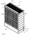
FIG. 1 is a diagram explaining a membrane separation device. -
FIG. 2 is a schematic diagram of the membrane separation device. -
FIG. 3A is a diagram explaining a membrane module;FIG. 3B is a diagram explaining a membrane element; andFIG. 3C is a schematic diagram of an elastic member. -
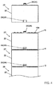
FIG. 4 is a diagram explaining a stack of the membrane modules. -
FIG. 5A is a diagram explaining an elastically deformed (compressed) state of the elastic member disposed between the membrane modules;FIG. 5B is a diagram explaining the elastic member in an uncompressed state. - Hereafter, the membrane separation device in accordance with the present invention is described. As shown in FIG. and
FIG. 2 , amembrane separation device 10 includes five rows of membrane module groups laterally arranged in aframe body 11 and submerged into liquid to be treated in a biological treatment tank, wheremembrane modules 20 are longitudinally arranged to form an eight-stage stack in each membrane module group. - The
frame body 11 is formed of a metal and includes alower frame 11, aside frame 11b, anupper frame 11c, and the like, since it is necessary for theframe body 11 to have a sufficient strength such that each of themembrane modules 20 is held in a stable position when themembrane modules 20 are arranged and submerged in the biological treatment tank, as well as the membrane modules 20accommodated therein are integrally submerged into or taken out of the biological treatment tank. - The
membrane modules 20 are made of a resin and the like. Because the volume of themembrane modules 20 will increase by absorbing water in the biological treatment tank, theframe body 11 is manufactured to have dimensions that take into account the expansion of the volume of themembrane modules 20. - A diffuser
air supply pipe 12 is provided under themembrane module 20 at the bottom of the stack in the biological treatment tank, and diffusion air supplied by the diffuserair supply pipe 20 causes an upward flow of the liquid to be treated between a plurality ofmembrane elements 21 which are in a longitudinal position and laterally arranged in a horizontal direction in each of themembrane module 20. The treated liquid which has been filtered through the membrane surface of eachmembrane element 21 is led to the outside of the tank via aliquid collection pipe 13. - The
liquid collection pipe 13 is in communication with a treated liquid delivery pipe (not shown) which leads to a treated liquid tank which is disposed outside the biological treatment tank, and a pumping apparatus is installed in a middle of the pipeline. The diffuserair supply pipe 12 is in communication with an air supply source such as a blower or a compressor. - The
upper frame 11c is provided with a stopper (closing member) 14 which closes an upper end portion of theframe body 11 such that the membrane module groups accommodated therein are not released from the upper end portion of theframe body 11. Thestopper 14 is made of a metal similar to theframe 11 and formed in a flat plate shape, and is fastened with bolts to theupper frame 11c which is disposed on the front and rear sides of each top-stage membrane module 20 of each of the membrane module groups which are laterally arranged in five rows. - An
elastic member 15 is disposed between themembrane modules 20 which are stacked in theframe body 11. The top-stage membrane modules 20 is pressed with a large force by thestopper 14, and theelastic body 15 arranged between themembrane modules 20 is in an elastically deformed state, that is, in this case, in a compressed state, thereby suppressing vibration in a vertical direction of themembrane modules 20 accommodated in theframe body 11 due to the upward flow caused by aeration of thediffuser device 12. - The
membrane modules 20 are explained below. As shown inFIG. 3A , eachmembrane module 20 includes a pair of front and rearliquid collection units 22, a pair of right andleft cover members 23, and a plurality ofmembrane elements 21. The plurality ofmembrane elements 21 are arranged in a longitudinal position with a fixed distance therebetween and disposed in a space defined by the pair of front and rearliquid collection units 22 and the pair of right andleft cover members 23 such that membrane surfaces are facing one another. - As shown in
FIG. 3B , eachmembrane element 21 is formed of afilter plate 21a in a form of a flat panel as a membrane support body, and aseparation membrane 21b, where theseparation membrane 21b is disposed on both sides of thefiler plate 21a. - The
liquid collection unit 22 is hollowed out such that the treated liquid which has been filtered through theseparation membrane 21b is guided to the inside of theliquid collection unit 22 through liquid collection passages formed in thefilter plate 21a. - A
filter plate 21a is formed of ABS resin and the like, and theseparation membrane 21b is formed by applying and impregnating a porous resin into a non-woven fabric as a base material. Thefilter plate 21a is not limited to a rigid material such as ABS resin, but may be formed using a flexible material such as a sheet-shaped non-woven fabric or a net. - The
collection units 22 and thecover members 23 are obtained by injection molding of ABS resin, polypropylene, or the like. It is preferable that thecollection units 22 are made of a transparent or translucent material such that it may be easy to check if the sludge flows into thecollection units 22 due to damages to theseparation membrane 21b and the like. - Each of the
liquid collection units 22 has acoupling portion 24 provided between and connecting and fixing themembrane modules 20 which are adjacent in the vertical direction. - The
coupling portion 24 includes anopening 26 which is in communication with the respectiveliquid collection units 22 of the verticallyadjacent membrane modules 20 such that the filtered liquid flows therethrough between theliquid collection units 22, and aninsertion portion 25 which is engaged with an inner wall of theopening 26 and fitted therein in a liquid-tight state. - As shown in
FIG. 4 , theinsertion portion 25 is liquid-tightly engaged with theopening 26 which is formed in theliquid collection unit 22 of themembrane module 20 stacked immediately thereabove, thereby providing communication between the adjacentliquid collection units 22 in the vertical direction. Consequently, themembrane modules 20 stacked inside theframe body 11 are coupled to one another at respective opposite surfaces of the correspondingliquid collection units 22 adjacent in the vertical direction and stably held in their position via thecoupling portions 24, while the filtered liquid which is collected from themembrane element 21 of eachmembrane module 20 into thecollection unit 22 is allowed to flow through thecoupling portions 24 which are coupled in a liquid-tight state. The filtered liquid passing through thecoupling portions 24 is led out to thecollection pipe 13 which is disposed in the vicinity of theupper frame 11c and inside thelower frame 11a. - The
elastic member 15 is explained below. As shown inFIG. 3C , theelastic member 15 is formed of a rubber sheet which is elastically deformable in a thickness direction thereof and formed to have a size similar to that of an upper surface of theliquid collection unit 22. -
Convex portions 15a which have a thickness greater than that of the rubber sheet are formed on the surface of the rubber sheet in a dispersed manner, and a cut-out portion having a U-shape is formed in a center portion of the rubber sheet such that theinsertion portion 25 is inserted therein when the rubber sheet is disposed between the opposing surfaces of theliquid collection units 22 of themembrane modules 20 adjacent in the vertical direction. - The
elastic member 15 is disposed between the opposing surfaces of theliquid collection unit 22 of themembrane modules 20 adjacent in the vertical direction. The coupling margin of thecoupling portion 24 and the thickness of theelastic member 15 are set such that theinsertion portion 25 remains inserted in theopening 26 in a liquid-tight state such that the coupling state of thecoupling portion 24 is maintained regardless of the extent of the elastic deformation of theelastic member 15. - For example, the coupling margin of the
coupling portion 24 and the thickness of theelastic member 15 are set such that theinsertion portion 25 remains inserted in theopening 26 in a liquid-tight state such that the coupling state of thecoupling portion 24 is maintained, whether thestopper 14 is fastened with the bolts so as to press the top-stage membrane module 20 with a large force such that theelastic member 15 is in an elastically deformed state as shown inFIG. 5A , or theelastic member 15 is in a non-compressed state without elastic deformation, as shown inFIG. 5B , as the total height of the eight stackedmembrane modules 20 becomes too smaller than the accommodation height of theframe body 11 due to the shrinking of the membrane modules such that tightening the bolts cannot make thestopper 14 press thetop membrane module 20 with a sufficiently large force. - In addition, a packing such as an O-shaped
ring 27 is disposed on an outer periphery of the insertion portion 25such that the packing is in pressure contact with the inner peripheral surface of theopening 26. However, the structure to form the liquid-tight state is not limited to this specific structure. - The coupling margin of the
coupling portion 24 is defined by the length of theinsertion portion 25 to maintain the liquid-tight state even when theelastic member 15 is in a non-compressed state, and the thickness of theelastic member 15 is defined by the weight of themembrane module 20, the material and dimensions of the rubber sheet, the number and size of theconvex portions 15a, and the like. - The
elastic member 15 may have, instead of theconvex portions 15a formed on the surface of the rubber sheet, concave portions or holes which have a thickness smaller than the thickness of the rubber sheet and formed on the rubber sheet in a distributed manner. In addition, it is possible to form convex portions, concave portions, and holes in combination. - Furthermore, the
elastic member 15 may be formed of, instead of a rubber sheet, a plurality of cylindrical rubber members corresponding to theconvex portions 15a which are arranged in a distributed manner. - In order to place the
elastic member 15 having a sheet-like shape between theadjacent membrane modules 20 and to maintain theelastic member 15 in a elastically deformed state, it is necessary to press themembrane modules 20 with a rather large force, and thus it is necessary for thestopper 14 which closes theframe body 11 and the end portion thereof to have a sufficient strength. This may limit the degree of freedom in designing theframe body 11, and the required thickness of the rubber sheet may disadvantageously increase the material cost. - However, the rubber sheet which is provided with the thicker convex portions or the thinner concave portions or holes formed thereon in a distributed manner partially and elastically deforms between the opposing surfaces of the
membrane modules 20 adjacent in the vertical direction so as to suppress the vibration, and thus it is possible to reduce the required pressing force onto themembrane modules 20 to suppress the vibration without extremely increasing the strength of thestopper 14 which closes the frame body and the end portion thereof, while the material cost for the rubber sheet can also be reduced. - As described above, since the
elastic member 15 is disposed, in an elastically deformed state, between themembrane modules 20 which are stacked in a state in which the upper end portion of theframe body 11 is closed by thestopper 14, even if the height of the group of the membrane modules is formed in advance to be smaller than the accommodation height from thelower frame 11a to thestopper 14 provided on theupper frame 11c, or even if the membrane modules shrink after manufacturing thereof, the vibration in the vertical direction of themembrane modules 20 within theframe body member 11 is effectively suppressed by theelastic member 15 such that themembrane modules 20 can be stably operated for a long pried of time. - Furthermore, not only the vibration of the
entire membrane modules 20 inside theframe body 11 is suppressed, but also, if a slight vibration occurs, abrasion caused between themembrane modules 20 is reliably prevented by providing theelastic member 15 between themembrane modules 20, and thus it possible to stably operate all of themembrane modules 20 for a long period of time. - Furthermore, when the membrane separation device is transported by loading in a bulk container and the like, more specifically, when such container transportation occurs in tropical regions right on the equator, for example, the temperature inside the container rises significantly, thereby causing such a phenomenon in which the
membrane modules 20 constituting the liquid collection units of the membrane modules expand under such a high temperature, and then shrink into a size smaller than the original size when the temperature returns to a room temperature, resulting in a smaller volume than the volume of the metal frame body. Even in such a case, vibration of themembrane modules 20 is properly suppressed during operation of themembrane separation device 10 so as to reliably avoid an undesirable situation such as collapsing of the stacking position of themembrane modules 20 due to release of the coupling state of thecoupling portions 24 inside theframe body 11. - The membrane separation device according to another embodiment of the present invention is described below. In the embodiment described above, the
elastic member 15 is made of a rubber sheet in a flat plate shape and disposed between themembrane modules 20. However, the shape and the location of the elastic member are not limited to these. For example, an elastic member of a block shape may be disposed between the top-stage membrane module 20 and thestopper 14, or between the bottom-stage membrane module 20 and thelower frame 11a. Any structure can be used so long as it can prevent vibrations of themembrane modules 20 within theframe body 11 during the operation of the membrane separation device. - In addition, the elastic member is not limited to a specific material or shape so long as it can prevent vibration of the membrane modules in the vertical direction, and may be a spring such as a coil spring made of a resin or metal or a leaf spring. The elastic member may also employ other elastically deformable materials such as synthetic rubber or natural rubber.
- Each embodiment described above is an example of the present invention, and thus the present invention is not limited by the description. A design of the specific structure of each part is appropriately changed so long as the function and effects of the present invention can be achieved.
-
- 10: Membrane separation device
- 11: Frame body
- 12: Diffuser air supply pipe
- 13: Liquid collection pipe
- 14: Stopper (Closing member)
- 15: Elastic member
- 15a: Convex portion
- 20: Membrane module
- 21: Membrane element
- 22: Liquid collection unit
- 23 : Cover member
- 24: Coupling portion
- 25: Insertion portion
- 26: Opening
- 27: O-shaped ring
Claims (5)
- A membrane separation device comprising:a plurality of membrane modules each including a plurality of membrane elements;a frame body accommodating the membrane modules by stacking the membrane modules in multiple stages;a closing member closing an end portion of the frame body so as to prevent the membrane modules accommodated in the frame body from being released; andan elastic member disposed in the frame body such that the elastic member is elastically deformed in a vertical direction in a state where the end portion of the frame body is closed.
- The membrane separation device of claim 1, wherein the elastic member is disposed between the membrane modules.
- The membrane separation device of claim 2, further comprising:a coupling portion configured to couple and fix the membrane modules adjacent in a vertical direction to each other, a coupling margin of the coupling portion and a thickness of the elastic member being set such that a coupling state of the coupling portion is maintained regardless of an extent of the elastic deformation of the elastic member.
- The membrane separation device of claim 3,
wherein each membrane module includes:a plurality of membrane elements, each including a membrane support body in a form of a flat panel or sheet and a separation membrane provided on a front surface and a rear surface of the support body, the plurality of membrane elements being arranged in a longitudinal position such that the separation membranes thereof face one another with a fixed distance provided therebetween; anda liquid collection unit provided in a traverse direction side portion of each of the membrane elements, the liquid collection portion being configured to collect filtered liquid permeated from each of the membrane elements.wherein the coupling portion includes:an opening in communication with the liquid collection unit of each of the adjacent membrane modules such that the filtered liquid flows therethrough; andan insertion portion configured to be engaged with an inner wall of the opening in a liquid-tight state,and wherein a length of the insertion portion to maintain the liquid-tight state defines the coupling margin. - The membrane separation device of any one of claims 2 to 4,
wherein the elastic member is formed of a rubber sheet configured to elastically deform in a thickness direction thereof, the elastic member being disposed between opposing surfaces of the membrane modules adjacent in the vertical direction, the elastic member including convex portions having a thickness greater than the thickness of the elastic member or concave portions or holes having a thickness smaller than the thickness of the elastic member.
Applications Claiming Priority (2)
| Application Number | Priority Date | Filing Date | Title |
|---|---|---|---|
| JP2011008131A JP5583036B2 (en) | 2011-01-18 | 2011-01-18 | Membrane separator |
| PCT/JP2012/050905 WO2012099144A1 (en) | 2011-01-18 | 2012-01-18 | Membrane separation device |
Publications (3)
| Publication Number | Publication Date |
|---|---|
| EP2666537A1 true EP2666537A1 (en) | 2013-11-27 |
| EP2666537A4 EP2666537A4 (en) | 2016-03-30 |
| EP2666537B1 EP2666537B1 (en) | 2020-04-15 |
Family
ID=46515767
Family Applications (1)
| Application Number | Title | Priority Date | Filing Date |
|---|---|---|---|
| EP12736914.8A Active EP2666537B1 (en) | 2011-01-18 | 2012-01-18 | Membrane separation device |
Country Status (5)
| Country | Link |
|---|---|
| US (1) | US10106440B2 (en) |
| EP (1) | EP2666537B1 (en) |
| JP (1) | JP5583036B2 (en) |
| CN (1) | CN103269779B (en) |
| WO (1) | WO2012099144A1 (en) |
Families Citing this family (12)
| Publication number | Priority date | Publication date | Assignee | Title |
|---|---|---|---|---|
| JP6089854B2 (en) * | 2013-03-26 | 2017-03-08 | 株式会社明電舎 | Membrane unit and membrane unit composite |
| CN105107382A (en) * | 2015-08-14 | 2015-12-02 | 上海世浦泰膜科技有限公司 | Dynamic self-balancing system for membrane module |
| JP6222284B1 (en) * | 2016-05-31 | 2017-11-01 | 株式会社明電舎 | Membrane element arrangement structure, membrane cassette and membrane unit |
| JP6222320B1 (en) * | 2016-09-21 | 2017-11-01 | 株式会社明電舎 | Membrane separator |
| SG10201911673PA (en) * | 2016-05-31 | 2020-02-27 | Meidensha Electric Mfg Co Ltd | Film separation device, structure for arranging film element, and film cassette and film unit |
| JP7421414B2 (en) | 2020-05-12 | 2024-01-24 | 株式会社クボタ | History management method and history management system for water treatment components |
| KR102418770B1 (en) * | 2020-08-18 | 2022-07-11 | 옥수금속(주) | Membrane unit for immersion type membrane separation system |
| CN113694737B (en) * | 2021-08-13 | 2024-05-03 | 万华化学集团股份有限公司 | Self-cleaning water inlet partition net and application |
| JP7844818B2 (en) * | 2021-08-26 | 2026-04-14 | 三菱ケミカル株式会社 | Membrane separation apparatus and water treatment method |
| CN114100371B (en) * | 2021-12-10 | 2024-04-09 | 雅安沃克林环保科技有限公司 | Dull and stereotyped membrane module of pottery and membrane heap |
| JP7363951B2 (en) * | 2022-03-23 | 2023-10-18 | 株式会社明電舎 | Filtration system and filtration treatment equipment |
| CN119869034B (en) * | 2025-03-17 | 2025-05-27 | 杭州科膜水处理工程有限公司 | High-efficient filtration membrane subassembly |
Family Cites Families (15)
| Publication number | Priority date | Publication date | Assignee | Title |
|---|---|---|---|---|
| JP3328149B2 (en) * | 1996-11-18 | 2002-09-24 | 株式会社クボタ | Immersion type membrane separation device |
| JP3333116B2 (en) * | 1997-08-08 | 2002-10-07 | 株式会社クボタ | Membrane separation device |
| JPH1157424A (en) * | 1997-08-08 | 1999-03-02 | Kubota Corp | Membrane separation device |
| JP2000271452A (en) * | 1999-03-24 | 2000-10-03 | Kubota Corp | Structure of the spacing case in a multi-stack immersion type membrane separator |
| JP2003019423A (en) * | 2002-06-25 | 2003-01-21 | Mitsubishi Rayon Co Ltd | Hollow fiber membrane module laminate |
| WO2005011833A2 (en) * | 2003-07-30 | 2005-02-10 | Phase Inc. | Filtration system with enhanced cleaning and dynamic fluid separation |
| AU2007242360B2 (en) * | 2006-03-27 | 2010-09-30 | Toray Industries, Inc. | Membrane element, membrane unit and multistage membrane unit |
| CN101405073A (en) * | 2006-03-27 | 2009-04-08 | 东丽株式会社 | Membrane element, membrane unit and multistage membrane unit |
| JP2008068162A (en) * | 2006-09-12 | 2008-03-27 | Kurita Water Ind Ltd | Water treatment filter and filter module |
| WO2009107559A1 (en) * | 2008-02-25 | 2009-09-03 | 日東電工株式会社 | Connection member and separation membrane module using the same |
| JP2009233571A (en) * | 2008-03-27 | 2009-10-15 | Toray Ind Inc | Element array fixing implement and membrane separation apparatus |
| EP2260926B1 (en) * | 2008-03-27 | 2018-09-05 | Kubota Corporation | Membrane module with slidable connectors |
| JP5187122B2 (en) * | 2008-10-15 | 2013-04-24 | 東レ株式会社 | Element array fixture and membrane separator |
| JP5257037B2 (en) * | 2008-12-05 | 2013-08-07 | 東レ株式会社 | Immersion membrane separation module and flat membrane element replacement method |
| US9446970B2 (en) * | 2009-02-24 | 2016-09-20 | Mitsubishi Rayon Co., Ltd. | Membrane module unit and assembly method, disassembly method, and maintenance method for same, and water-treatment apparatus |
-
2011
- 2011-01-18 JP JP2011008131A patent/JP5583036B2/en active Active
-
2012
- 2012-01-18 CN CN201280003789.5A patent/CN103269779B/en active Active
- 2012-01-18 EP EP12736914.8A patent/EP2666537B1/en active Active
- 2012-01-18 WO PCT/JP2012/050905 patent/WO2012099144A1/en not_active Ceased
-
2013
- 2013-07-17 US US13/944,540 patent/US10106440B2/en active Active
Also Published As
| Publication number | Publication date |
|---|---|
| JP2012148229A (en) | 2012-08-09 |
| JP5583036B2 (en) | 2014-09-03 |
| CN103269779A (en) | 2013-08-28 |
| WO2012099144A1 (en) | 2012-07-26 |
| EP2666537A4 (en) | 2016-03-30 |
| EP2666537B1 (en) | 2020-04-15 |
| CN103269779B (en) | 2016-03-30 |
| US10106440B2 (en) | 2018-10-23 |
| US20130299413A1 (en) | 2013-11-14 |
Similar Documents
| Publication | Publication Date | Title |
|---|---|---|
| US10106440B2 (en) | Membrane separation device | |
| US10040701B2 (en) | Membrane separation device | |
| KR102077361B1 (en) | Separation membrane module | |
| EP3075438B1 (en) | Method for lifting membrane separation apparatus | |
| WO2005042133A1 (en) | Hollow fiber membrane module, hollow fiber membrane module unit, and water treatment method | |
| CN103476475B (en) | filter | |
| TW200920471A (en) | Membrane element and membrane separating apparatus | |
| KR100988838B1 (en) | Membrane module for water treatment and filtration device to which this membrane module is applied | |
| KR101507256B1 (en) | Hollow fiber membrane module | |
| TW200706234A (en) | Filtration device | |
| JPH0999222A (en) | Hollow fiber membrane module unit and filtration device | |
| JP6156480B2 (en) | Membrane cassette and membrane unit | |
| JP6319463B2 (en) | Membrane filtration unit and water treatment method | |
| CN104703678A (en) | Stacks of membrane filter bags often sealed at their corners | |
| JP2004113882A (en) | Immersion flat membrane module | |
| JP2012030146A (en) | Immersion type membrane separator | |
| JP2012030145A (en) | Immersion type membrane separator | |
| CN207708847U (en) | Membrane element | |
| KR101262008B1 (en) | Immersion Type Membrane Separator Device And Driving Method Of The Same | |
| JP5257037B2 (en) | Immersion membrane separation module and flat membrane element replacement method | |
| JP7844818B2 (en) | Membrane separation apparatus and water treatment method | |
| CN105107245B (en) | Filtering apparatus | |
| KR101105203B1 (en) | Immersion Hollow Fiber Membrane Filtration Module | |
| JP2013121569A (en) | Cylindrical air diffusion device, and method for manufacturing the same |
Legal Events
| Date | Code | Title | Description |
|---|---|---|---|
| PUAI | Public reference made under article 153(3) epc to a published international application that has entered the european phase |
Free format text: ORIGINAL CODE: 0009012 |
|
| 17P | Request for examination filed |
Effective date: 20130718 |
|
| AK | Designated contracting states |
Kind code of ref document: A1 Designated state(s): AL AT BE BG CH CY CZ DE DK EE ES FI FR GB GR HR HU IE IS IT LI LT LU LV MC MK MT NL NO PL PT RO RS SE SI SK SM TR |
|
| DAX | Request for extension of the european patent (deleted) | ||
| RA4 | Supplementary search report drawn up and despatched (corrected) |
Effective date: 20160301 |
|
| RIC1 | Information provided on ipc code assigned before grant |
Ipc: B01D 65/08 20060101ALI20160224BHEP Ipc: B01D 63/00 20060101ALI20160224BHEP Ipc: B01D 65/00 20060101ALI20160224BHEP Ipc: C02F 1/44 20060101ALI20160224BHEP Ipc: B01D 63/08 20060101AFI20160224BHEP |
|
| STAA | Information on the status of an ep patent application or granted ep patent |
Free format text: STATUS: EXAMINATION IS IN PROGRESS |
|
| 17Q | First examination report despatched |
Effective date: 20180321 |
|
| GRAP | Despatch of communication of intention to grant a patent |
Free format text: ORIGINAL CODE: EPIDOSNIGR1 |
|
| STAA | Information on the status of an ep patent application or granted ep patent |
Free format text: STATUS: GRANT OF PATENT IS INTENDED |
|
| INTG | Intention to grant announced |
Effective date: 20191127 |
|
| GRAS | Grant fee paid |
Free format text: ORIGINAL CODE: EPIDOSNIGR3 |
|
| GRAA | (expected) grant |
Free format text: ORIGINAL CODE: 0009210 |
|
| STAA | Information on the status of an ep patent application or granted ep patent |
Free format text: STATUS: THE PATENT HAS BEEN GRANTED |
|
| AK | Designated contracting states |
Kind code of ref document: B1 Designated state(s): AL AT BE BG CH CY CZ DE DK EE ES FI FR GB GR HR HU IE IS IT LI LT LU LV MC MK MT NL NO PL PT RO RS SE SI SK SM TR |
|
| REG | Reference to a national code |
Ref country code: GB Ref legal event code: FG4D Ref country code: CH Ref legal event code: EP |
|
| REG | Reference to a national code |
Ref country code: DE Ref legal event code: R096 Ref document number: 602012069298 Country of ref document: DE |
|
| REG | Reference to a national code |
Ref country code: IE Ref legal event code: FG4D |
|
| REG | Reference to a national code |
Ref country code: AT Ref legal event code: REF Ref document number: 1256600 Country of ref document: AT Kind code of ref document: T Effective date: 20200515 |
|
| REG | Reference to a national code |
Ref country code: NL Ref legal event code: MP Effective date: 20200415 |
|
| REG | Reference to a national code |
Ref country code: LT Ref legal event code: MG4D |
|
| PG25 | Lapsed in a contracting state [announced via postgrant information from national office to epo] |
Ref country code: IS Free format text: LAPSE BECAUSE OF FAILURE TO SUBMIT A TRANSLATION OF THE DESCRIPTION OR TO PAY THE FEE WITHIN THE PRESCRIBED TIME-LIMIT Effective date: 20200815 Ref country code: SE Free format text: LAPSE BECAUSE OF FAILURE TO SUBMIT A TRANSLATION OF THE DESCRIPTION OR TO PAY THE FEE WITHIN THE PRESCRIBED TIME-LIMIT Effective date: 20200415 Ref country code: GR Free format text: LAPSE BECAUSE OF FAILURE TO SUBMIT A TRANSLATION OF THE DESCRIPTION OR TO PAY THE FEE WITHIN THE PRESCRIBED TIME-LIMIT Effective date: 20200716 Ref country code: NO Free format text: LAPSE BECAUSE OF FAILURE TO SUBMIT A TRANSLATION OF THE DESCRIPTION OR TO PAY THE FEE WITHIN THE PRESCRIBED TIME-LIMIT Effective date: 20200715 Ref country code: FI Free format text: LAPSE BECAUSE OF FAILURE TO SUBMIT A TRANSLATION OF THE DESCRIPTION OR TO PAY THE FEE WITHIN THE PRESCRIBED TIME-LIMIT Effective date: 20200415 Ref country code: NL Free format text: LAPSE BECAUSE OF FAILURE TO SUBMIT A TRANSLATION OF THE DESCRIPTION OR TO PAY THE FEE WITHIN THE PRESCRIBED TIME-LIMIT Effective date: 20200415 Ref country code: PT Free format text: LAPSE BECAUSE OF FAILURE TO SUBMIT A TRANSLATION OF THE DESCRIPTION OR TO PAY THE FEE WITHIN THE PRESCRIBED TIME-LIMIT Effective date: 20200817 Ref country code: LT Free format text: LAPSE BECAUSE OF FAILURE TO SUBMIT A TRANSLATION OF THE DESCRIPTION OR TO PAY THE FEE WITHIN THE PRESCRIBED TIME-LIMIT Effective date: 20200415 |
|
| REG | Reference to a national code |
Ref country code: AT Ref legal event code: MK05 Ref document number: 1256600 Country of ref document: AT Kind code of ref document: T Effective date: 20200415 |
|
| PG25 | Lapsed in a contracting state [announced via postgrant information from national office to epo] |
Ref country code: BG Free format text: LAPSE BECAUSE OF FAILURE TO SUBMIT A TRANSLATION OF THE DESCRIPTION OR TO PAY THE FEE WITHIN THE PRESCRIBED TIME-LIMIT Effective date: 20200715 Ref country code: HR Free format text: LAPSE BECAUSE OF FAILURE TO SUBMIT A TRANSLATION OF THE DESCRIPTION OR TO PAY THE FEE WITHIN THE PRESCRIBED TIME-LIMIT Effective date: 20200415 Ref country code: RS Free format text: LAPSE BECAUSE OF FAILURE TO SUBMIT A TRANSLATION OF THE DESCRIPTION OR TO PAY THE FEE WITHIN THE PRESCRIBED TIME-LIMIT Effective date: 20200415 Ref country code: LV Free format text: LAPSE BECAUSE OF FAILURE TO SUBMIT A TRANSLATION OF THE DESCRIPTION OR TO PAY THE FEE WITHIN THE PRESCRIBED TIME-LIMIT Effective date: 20200415 |
|
| PG25 | Lapsed in a contracting state [announced via postgrant information from national office to epo] |
Ref country code: AL Free format text: LAPSE BECAUSE OF FAILURE TO SUBMIT A TRANSLATION OF THE DESCRIPTION OR TO PAY THE FEE WITHIN THE PRESCRIBED TIME-LIMIT Effective date: 20200415 |
|
| REG | Reference to a national code |
Ref country code: DE Ref legal event code: R097 Ref document number: 602012069298 Country of ref document: DE |
|
| PG25 | Lapsed in a contracting state [announced via postgrant information from national office to epo] |
Ref country code: AT Free format text: LAPSE BECAUSE OF FAILURE TO SUBMIT A TRANSLATION OF THE DESCRIPTION OR TO PAY THE FEE WITHIN THE PRESCRIBED TIME-LIMIT Effective date: 20200415 Ref country code: EE Free format text: LAPSE BECAUSE OF FAILURE TO SUBMIT A TRANSLATION OF THE DESCRIPTION OR TO PAY THE FEE WITHIN THE PRESCRIBED TIME-LIMIT Effective date: 20200415 Ref country code: SM Free format text: LAPSE BECAUSE OF FAILURE TO SUBMIT A TRANSLATION OF THE DESCRIPTION OR TO PAY THE FEE WITHIN THE PRESCRIBED TIME-LIMIT Effective date: 20200415 Ref country code: DK Free format text: LAPSE BECAUSE OF FAILURE TO SUBMIT A TRANSLATION OF THE DESCRIPTION OR TO PAY THE FEE WITHIN THE PRESCRIBED TIME-LIMIT Effective date: 20200415 Ref country code: CZ Free format text: LAPSE BECAUSE OF FAILURE TO SUBMIT A TRANSLATION OF THE DESCRIPTION OR TO PAY THE FEE WITHIN THE PRESCRIBED TIME-LIMIT Effective date: 20200415 Ref country code: RO Free format text: LAPSE BECAUSE OF FAILURE TO SUBMIT A TRANSLATION OF THE DESCRIPTION OR TO PAY THE FEE WITHIN THE PRESCRIBED TIME-LIMIT Effective date: 20200415 Ref country code: ES Free format text: LAPSE BECAUSE OF FAILURE TO SUBMIT A TRANSLATION OF THE DESCRIPTION OR TO PAY THE FEE WITHIN THE PRESCRIBED TIME-LIMIT Effective date: 20200415 |
|
| PLBE | No opposition filed within time limit |
Free format text: ORIGINAL CODE: 0009261 |
|
| STAA | Information on the status of an ep patent application or granted ep patent |
Free format text: STATUS: NO OPPOSITION FILED WITHIN TIME LIMIT |
|
| PG25 | Lapsed in a contracting state [announced via postgrant information from national office to epo] |
Ref country code: PL Free format text: LAPSE BECAUSE OF FAILURE TO SUBMIT A TRANSLATION OF THE DESCRIPTION OR TO PAY THE FEE WITHIN THE PRESCRIBED TIME-LIMIT Effective date: 20200415 Ref country code: SK Free format text: LAPSE BECAUSE OF FAILURE TO SUBMIT A TRANSLATION OF THE DESCRIPTION OR TO PAY THE FEE WITHIN THE PRESCRIBED TIME-LIMIT Effective date: 20200415 |
|
| 26N | No opposition filed |
Effective date: 20210118 |
|
| PG25 | Lapsed in a contracting state [announced via postgrant information from national office to epo] |
Ref country code: SI Free format text: LAPSE BECAUSE OF FAILURE TO SUBMIT A TRANSLATION OF THE DESCRIPTION OR TO PAY THE FEE WITHIN THE PRESCRIBED TIME-LIMIT Effective date: 20200415 |
|
| REG | Reference to a national code |
Ref country code: DE Ref legal event code: R119 Ref document number: 602012069298 Country of ref document: DE |
|
| PG25 | Lapsed in a contracting state [announced via postgrant information from national office to epo] |
Ref country code: MC Free format text: LAPSE BECAUSE OF FAILURE TO SUBMIT A TRANSLATION OF THE DESCRIPTION OR TO PAY THE FEE WITHIN THE PRESCRIBED TIME-LIMIT Effective date: 20200415 |
|
| REG | Reference to a national code |
Ref country code: CH Ref legal event code: PL |
|
| PG25 | Lapsed in a contracting state [announced via postgrant information from national office to epo] |
Ref country code: LU Free format text: LAPSE BECAUSE OF NON-PAYMENT OF DUE FEES Effective date: 20210118 |
|
| PG25 | Lapsed in a contracting state [announced via postgrant information from national office to epo] |
Ref country code: DE Free format text: LAPSE BECAUSE OF NON-PAYMENT OF DUE FEES Effective date: 20210803 Ref country code: CH Free format text: LAPSE BECAUSE OF NON-PAYMENT OF DUE FEES Effective date: 20210131 Ref country code: LI Free format text: LAPSE BECAUSE OF NON-PAYMENT OF DUE FEES Effective date: 20210131 |
|
| PG25 | Lapsed in a contracting state [announced via postgrant information from national office to epo] |
Ref country code: IE Free format text: LAPSE BECAUSE OF NON-PAYMENT OF DUE FEES Effective date: 20210118 |
|
| PG25 | Lapsed in a contracting state [announced via postgrant information from national office to epo] |
Ref country code: HU Free format text: LAPSE BECAUSE OF FAILURE TO SUBMIT A TRANSLATION OF THE DESCRIPTION OR TO PAY THE FEE WITHIN THE PRESCRIBED TIME-LIMIT; INVALID AB INITIO Effective date: 20120118 Ref country code: CY Free format text: LAPSE BECAUSE OF FAILURE TO SUBMIT A TRANSLATION OF THE DESCRIPTION OR TO PAY THE FEE WITHIN THE PRESCRIBED TIME-LIMIT Effective date: 20200415 |
|
| PG25 | Lapsed in a contracting state [announced via postgrant information from national office to epo] |
Ref country code: MK Free format text: LAPSE BECAUSE OF FAILURE TO SUBMIT A TRANSLATION OF THE DESCRIPTION OR TO PAY THE FEE WITHIN THE PRESCRIBED TIME-LIMIT Effective date: 20200415 |
|
| PG25 | Lapsed in a contracting state [announced via postgrant information from national office to epo] |
Ref country code: TR Free format text: LAPSE BECAUSE OF FAILURE TO SUBMIT A TRANSLATION OF THE DESCRIPTION OR TO PAY THE FEE WITHIN THE PRESCRIBED TIME-LIMIT Effective date: 20200415 |
|
| PG25 | Lapsed in a contracting state [announced via postgrant information from national office to epo] |
Ref country code: MT Free format text: LAPSE BECAUSE OF FAILURE TO SUBMIT A TRANSLATION OF THE DESCRIPTION OR TO PAY THE FEE WITHIN THE PRESCRIBED TIME-LIMIT Effective date: 20200415 |
|
| PGFP | Annual fee paid to national office [announced via postgrant information from national office to epo] |
Ref country code: GB Payment date: 20251127 Year of fee payment: 15 |
|
| PGFP | Annual fee paid to national office [announced via postgrant information from national office to epo] |
Ref country code: FR Payment date: 20251128 Year of fee payment: 15 |
|
| PGFP | Annual fee paid to national office [announced via postgrant information from national office to epo] |
Ref country code: BE Payment date: 20251223 Year of fee payment: 15 |
|
| PGFP | Annual fee paid to national office [announced via postgrant information from national office to epo] |
Ref country code: IT Payment date: 20251219 Year of fee payment: 15 |