EP2666491A1 - Hämodialysegerät - Google Patents
Hämodialysegerät Download PDFInfo
- Publication number
- EP2666491A1 EP2666491A1 EP12168954.1A EP12168954A EP2666491A1 EP 2666491 A1 EP2666491 A1 EP 2666491A1 EP 12168954 A EP12168954 A EP 12168954A EP 2666491 A1 EP2666491 A1 EP 2666491A1
- Authority
- EP
- European Patent Office
- Prior art keywords
- pump
- substituate
- dialysate
- dialyzer
- hemodialysis machine
- Prior art date
- Legal status (The legal status is an assumption and is not a legal conclusion. Google has not performed a legal analysis and makes no representation as to the accuracy of the status listed.)
- Granted
Links
Images


Classifications
-
- A—HUMAN NECESSITIES
- A61—MEDICAL OR VETERINARY SCIENCE; HYGIENE
- A61M—DEVICES FOR INTRODUCING MEDIA INTO, OR ONTO, THE BODY; DEVICES FOR TRANSDUCING BODY MEDIA OR FOR TAKING MEDIA FROM THE BODY; DEVICES FOR PRODUCING OR ENDING SLEEP OR STUPOR
- A61M1/00—Suction or pumping devices for medical purposes; Devices for carrying-off, for treatment of, or for carrying-over, body-liquids; Drainage systems
- A61M1/34—Filtering material out of the blood by passing it through a membrane, i.e. hemofiltration or diafiltration
- A61M1/342—Adding solutions to the blood, e.g. substitution solutions
-
- A—HUMAN NECESSITIES
- A61—MEDICAL OR VETERINARY SCIENCE; HYGIENE
- A61M—DEVICES FOR INTRODUCING MEDIA INTO, OR ONTO, THE BODY; DEVICES FOR TRANSDUCING BODY MEDIA OR FOR TAKING MEDIA FROM THE BODY; DEVICES FOR PRODUCING OR ENDING SLEEP OR STUPOR
- A61M1/00—Suction or pumping devices for medical purposes; Devices for carrying-off, for treatment of, or for carrying-over, body-liquids; Drainage systems
- A61M1/14—Dialysis systems; Artificial kidneys; Blood oxygenators ; Reciprocating systems for treatment of body fluids, e.g. single needle systems for hemofiltration or pheresis
- A61M1/16—Dialysis systems; Artificial kidneys; Blood oxygenators ; Reciprocating systems for treatment of body fluids, e.g. single needle systems for hemofiltration or pheresis with membranes
- A61M1/1621—Constructional aspects thereof
- A61M1/1635—Constructional aspects thereof with volume chamber balancing devices between used and fresh dialysis fluid
- A61M1/1639—Constructional aspects thereof with volume chamber balancing devices between used and fresh dialysis fluid linked by membranes
-
- A—HUMAN NECESSITIES
- A61—MEDICAL OR VETERINARY SCIENCE; HYGIENE
- A61M—DEVICES FOR INTRODUCING MEDIA INTO, OR ONTO, THE BODY; DEVICES FOR TRANSDUCING BODY MEDIA OR FOR TAKING MEDIA FROM THE BODY; DEVICES FOR PRODUCING OR ENDING SLEEP OR STUPOR
- A61M1/00—Suction or pumping devices for medical purposes; Devices for carrying-off, for treatment of, or for carrying-over, body-liquids; Drainage systems
- A61M1/14—Dialysis systems; Artificial kidneys; Blood oxygenators ; Reciprocating systems for treatment of body fluids, e.g. single needle systems for hemofiltration or pheresis
- A61M1/16—Dialysis systems; Artificial kidneys; Blood oxygenators ; Reciprocating systems for treatment of body fluids, e.g. single needle systems for hemofiltration or pheresis with membranes
- A61M1/1621—Constructional aspects thereof
- A61M1/1645—Constructional aspects thereof with mechanically linked peristaltic dialysis fluid pumps one upstream, the other one downstream of the dialyser
-
- A—HUMAN NECESSITIES
- A61—MEDICAL OR VETERINARY SCIENCE; HYGIENE
- A61M—DEVICES FOR INTRODUCING MEDIA INTO, OR ONTO, THE BODY; DEVICES FOR TRANSDUCING BODY MEDIA OR FOR TAKING MEDIA FROM THE BODY; DEVICES FOR PRODUCING OR ENDING SLEEP OR STUPOR
- A61M1/00—Suction or pumping devices for medical purposes; Devices for carrying-off, for treatment of, or for carrying-over, body-liquids; Drainage systems
- A61M1/34—Filtering material out of the blood by passing it through a membrane, i.e. hemofiltration or diafiltration
- A61M1/342—Adding solutions to the blood, e.g. substitution solutions
- A61M1/3424—Substitution fluid path
- A61M1/3431—Substitution fluid path upstream of the filter
- A61M1/3434—Substitution fluid path upstream of the filter with pre-dilution and post-dilution
-
- A—HUMAN NECESSITIES
- A61—MEDICAL OR VETERINARY SCIENCE; HYGIENE
- A61M—DEVICES FOR INTRODUCING MEDIA INTO, OR ONTO, THE BODY; DEVICES FOR TRANSDUCING BODY MEDIA OR FOR TAKING MEDIA FROM THE BODY; DEVICES FOR PRODUCING OR ENDING SLEEP OR STUPOR
- A61M1/00—Suction or pumping devices for medical purposes; Devices for carrying-off, for treatment of, or for carrying-over, body-liquids; Drainage systems
- A61M1/34—Filtering material out of the blood by passing it through a membrane, i.e. hemofiltration or diafiltration
- A61M1/342—Adding solutions to the blood, e.g. substitution solutions
- A61M1/3424—Substitution fluid path
- A61M1/3437—Substitution fluid path downstream of the filter, e.g. post-dilution with filtrate
-
- A—HUMAN NECESSITIES
- A61—MEDICAL OR VETERINARY SCIENCE; HYGIENE
- A61M—DEVICES FOR INTRODUCING MEDIA INTO, OR ONTO, THE BODY; DEVICES FOR TRANSDUCING BODY MEDIA OR FOR TAKING MEDIA FROM THE BODY; DEVICES FOR PRODUCING OR ENDING SLEEP OR STUPOR
- A61M1/00—Suction or pumping devices for medical purposes; Devices for carrying-off, for treatment of, or for carrying-over, body-liquids; Drainage systems
- A61M1/34—Filtering material out of the blood by passing it through a membrane, i.e. hemofiltration or diafiltration
- A61M1/342—Adding solutions to the blood, e.g. substitution solutions
- A61M1/3441—Substitution rate control as a function of the ultrafiltration rate
- A61M1/3448—Substitution rate control as a function of the ultrafiltration rate by mechanically linked pumps in both ultra-filtrate and substitution flow line
-
- A—HUMAN NECESSITIES
- A61—MEDICAL OR VETERINARY SCIENCE; HYGIENE
- A61M—DEVICES FOR INTRODUCING MEDIA INTO, OR ONTO, THE BODY; DEVICES FOR TRANSDUCING BODY MEDIA OR FOR TAKING MEDIA FROM THE BODY; DEVICES FOR PRODUCING OR ENDING SLEEP OR STUPOR
- A61M1/00—Suction or pumping devices for medical purposes; Devices for carrying-off, for treatment of, or for carrying-over, body-liquids; Drainage systems
- A61M1/34—Filtering material out of the blood by passing it through a membrane, i.e. hemofiltration or diafiltration
- A61M1/342—Adding solutions to the blood, e.g. substitution solutions
- A61M1/3455—Substitution fluids
- A61M1/3465—Substitution fluids using dialysate as substitution fluid
Definitions
- the invention relates to a hemodialysis machine which has a permanently used and disinfectable internal fluid and disposable disposable external fluidics.
- internal fluidics include, in particular, dialysate fluidity, including a balancing pump, which is formed from a dialysate pump and a waste pump which is forcibly coupled thereto.
- the coupling may be mechanical or otherwise, for example in the form of a programmed forced coupling.
- the dialysate pump pumps dialysate from a dialysate source to the dialysate chamber of a dialyzer.
- the waste pump pumps the dialysate from the dialyzer to a waste destination, such as a waste bin.
- the entire blood side including the arterial line and the venous line, which are both connected to a blood chamber of the dialyzer, belongs to the single-use disposable external fluid designed as a tube set.
- a substituate tubing which is connected to the dialysis source via a corresponding device coupling and establishes a connection to a substituent access on one of the blood-side tubing.
- the external pumps are designed as peristaltic peristaltic pumps, wherein the pump mimic is provided externally accessible on the outside of the hemodialysis machine.
- Peristaltic pumps are inherently subject to an inaccuracy of the order of 10% with respect to the flow rate. To a simple one and ensure error-free application of the external fluid tubing set into the external pump mimic, the external tubing set in these areas is provided with elaborate pump adapters.
- the object of the invention is in contrast to provide a hemodialysis machine with an easy-to-handle external fluidics.
- the substituate pump is disposed in the internal fluid, that is, the substituate pump is not formed as an external pump whose liquid-conducting portion is exchangeable. Therefore, it does not necessarily have to be designed as a relatively inaccurate peristaltic peristaltic pump, but rather may for example be designed as a relatively accurate piston pump. Since the internal Substituatpumpe has no liquid-carrying parts that are interchangeable, the Substituatpumpe is designed to be disinfected.
- a fluidic substituate coupling is preferably provided, via which the substituate pump is fluidically connected to the substituate access via a further substituate line of the external fluidics. Since the substituate pump is arranged in the internal fluid, the application of the external fluid tubing set is considerably simplified. Furthermore, the external external fluid tubing set is considerably simpler and cheaper due to the elimination of a pump adapter.
- the supply line of the substituate pump is fluidically connected between the dialysate pump and the dialyzer within the internal fluidics.
- the dialysate for the substituate pump is therefore branched off behind the dialysate pump, as seen in the flow direction. Since the dialysate pump and the waste pump are formed together as balancing pump, the blood-side lines on the dialyzer membrane of the dialyzer is always withdrawn as much liquid as supplied to the relevant blood-side line via the Substituat ein becomes. The amount of liquid which is supplied to the blood-side lines via the substituate access is ultrafiltered through the dialyzer membrane from the blood chamber to the dialysate chamber.
- the supply line to the substituate pump can be fluidically connected between the dialysate source and the dialysate pump, wherein an ultrafiltration pump which can be operated in parallel flow is then provided fluidically parallel to the waste pump.
- another pump namely preferably the ultrafiltration pump, is provided in the dialysate-side waste branch, which can be operated parallel to the waste pump and in the same direction as the waste pump, for a volume-neutral substitution.
- the pumping rate of the ultrafiltration pump should always correspond to the pumping rate of the substituate pump if a volume-neutral substitution is desired.
- the substituate access can be arranged in this constellation in the internal fluid, so that a substituate coupling is omitted.
- the substituate pump is designed as a non-peristaltic positive displacement pump.
- the substituate pump is designed as a ceramic piston pump.
- a positive displacement pump provides single-digit volumetric accuracy. The training as a ceramic pump ensures a long life, high long-term accuracy and easy disinfectability.
- the substituate access to the blood-side conduit upstream of the dialyzer is provided, so that the substituate access opens into the arterial line.
- the substituate access may also be provided downstream of the dialyzer, ie open into the venous line behind the dialyzer.
- the substituate access on the blood side can be arranged directly on the blood chamber of the dialyzer.
- a second substituate coupling connected to the substituate pump and a valve arrangement between the substituate pump and the two substituate couplings are provided. The two substituate couplings are linked to two different externally fluid substituent accesses.
- valve arrangement it is possible alternatively to switch between the two different substituent accesses, for example between a substituent access downstream and a substituent access upstream of the dialyzer.
- the substituate pump is fluidically associated in series with a flow sensor.
- the flow sensor is in particular arranged fluidically in front of the substituate coupling, for example immediately downstream or upstream of the substituate pump.
- the substituate pump flow can be determined exactly. This is necessary in particular when the supply line of the substituate pump is connected fluidically upstream of the dialysate pump.
- the ultrafiltration pump can then be operated at a pumping rate which corresponds exactly to the flow rate measured by the flow sensor.
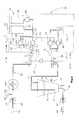
- a hemodialysis apparatus 10 is shown schematically, which can be functionally subdivided into a dialysate side 15 and a blood side 16.
- the boundary between the dialysate side 15 and the blood side 16 is formed by a dialysis membrane 56 in a dialyzer 50.
- the dialysis membrane 56 separates a dialysate chamber 52 from a blood chamber 54 in the dialyzer 50.
- the hemodialysis machine 10 is subdivided into a repeatedly usable and disinfectable internal fluid 12 within a device housing 11 on the one hand and an exchangeable disposable external fluid 14 outside the device housing 11 must not be disinfected and is replaced after each dialysis treatment.
- the dialysate side 12 has a dialysate source 20 which provides dialysate for dialysis.
- the dialysate also serves as a substituate, so that the dialysate source 20 can also be referred to as Substituatán.
- the dialysate source 20 is formed by a dialysis water tank 22 with dialysis water 24 and an additive tank 26 with a dialysate additive 28.
- the additive tank 26 is followed by an additive pump 29, the well-dosed an additive 28 when needed the Dialysis water supply power. It is also possible to provide a plurality of additive tanks, in particular electrolytes and buffer substances being provided as additives.
- the dialysis water may also be provided by a water treatment device (not shown) in which the dialysis water is produced from drinking water from the public pipeline network.
- the dialysate or the identical substituate liquid from the dialysate source 20 is pumped through a dilatation pump 32 via a dialysate 25 into the dialysate 52 of the dialyzer 50.
- a line passes to a waste pump 34, which pumps the dialysate from the dialysate chamber 52 into a waste tank 42, which is the waste target, and in which the spent dialysate is stored during the dialysis treatment.
- the dialysate pump 32 and the waste pump 34 are mechanically interconnected by a mechanical connection 36, so that the pumping rates of the dialysate pump 32 and the waste pump 34 are always absolutely identical. In this way, the dialysate pump 32 and the waste pump 34 form a so-called balancing pump 30.
- the mechanical connection 36 can be realized, for example, in that the balancing pump 30 is designed as a diaphragm pump, wherein one side of the pump diaphragm, the pumping chamber of the dialysate pump 32 and the other side the pump diaphragm limits the pumping chamber of the waste pump 34.
- the blood chamber 54 of the dialyzer. 50 On the blood side 15 of the dialyzer membrane 56 is the blood chamber 54 of the dialyzer. 50, in which an arterial line 60 and a venous line 80 open.
- a blood pump 61 which is designed as a peristaltic peristaltic pump, wherein the peristaltic pumping mimic is arranged on the device housing 11, in which the flexible tube formed as a line 60 is inserted.
- the pumping rate of the blood pump 61 is controlled by a device controller, not shown.
- an arterial pressure sensor 62 Arranged in the course of the arterial line 60 is an arterial pressure sensor 62, by means of which the static fluid pressure in the arterial line is detected. Also, the arterial pressure sensor 62 is connected to the device controller.
- an arterial tube clamp 64 which can close or open the arterial line 60, which is a flexible tube.
- an arterial cannula 66 Arranged at the end of the arterial line 60 is an arterial cannula 66, which has a needle with which the arterial line 60 can be applied to a blood vessel of a patient, from which the blood pump 61 sucks patient blood into the arterial line 60 to carry out the actual blood purification ,
- an air trap 70 is arranged, which has a dip tube 76 with a downwardly opening tube opening 77.
- the tube opening 77 is located far below a liquid level 74, the height of which is regulated to a desired level via a separate overhead gas connection (not shown) and a level control pump (not shown) connected thereto.
- the level control pump ensures that the tube opening 77 is always below the liquid level 74.
- a venous pressure sensor 72 is also arranged, which detects the fluid pressure in the venous line 80.
- the pressure sensor 72 may also be connected to the gas connection for the level control pump.
- a venous line clamp 82 is provided with the Device control is connected and represents a switchable valve that closes or opens the venous line 80.
- a venous cannula 84 is provided which has a needle so that the venous cannula 84 can be applied at the beginning of the actual blood purification to a corresponding venous blood vessel of the patient.
- a Substituatpumpe 90 is disposed within the device housing 11, which pumps dialysate or substituate to an external substituent access 98, which is arranged on the arterial line 60 upstream of the dialyzer blood chamber 54.
- a first dialysate filter 44 is arranged, which, together with a second dialysate filter 44, ensures the sterility of the exiting dialysate or substituate redundantly.
- the second dialysate filter 44 can also be arranged directly behind the dialysate pump 32 as an integrated or separate filter.
- the dialysate filter 44 can also be arranged fluidically behind the relevant substituate pump.
- the supply line 94 of the substituate pump 90 is fluidly branched off from the dialysate line 25 between the dialysate pump 32 and the dialyzer 50 within the device housing 11. Downstream of the substituate pump 90 is a flow sensor 92 which quantitatively detects the substituate flow.
- the Substituatpumpe 90, its supply line 94 and the flow sensor 92 are disposed within the device housing 11, so belong to the internal fluidics 12.
- On the operating side 13 of the hemodialysis machine 10 is a Substituat- coupling 96 is arranged, with respect to the SubstituatLeitung the interface between the Internfluidik 12 and the external fluid 14 represents.
- To the Substituatkupplung 96 is the external fluidic substituate line 97 leading to the substituate access 98.
- a dialyzate coupling 33 and a waste coupling 35 are respectively provided on the device operator side 13.
- the aforementioned line couplings 96, 33, 35 each represent the fluidic interface between the internal fluid 12 and the external fluid 14.
- the balancing pump 30 runs continuously, so that dialysate or substituate is continuously conveyed from the dialysate source 20 through the dialysate pump 32.
- the substituate pump 90 delivers substituate to the substituate access 98 at a pumping rate below the pumping rate of the dialysate pump 32.
- the dialyzer is used in the dialyzer with an ultrafiltration rate corresponding to the pumping rate of the substituate pump 90 plus the ultrafiltration rate of the patient through the dialyzer Membrane 56 is ultrafiltered through to the dialysate side 16.
- FIG. 2 another embodiment of a hemodialysis machine 10 is shown, wherein the essential difference from the hemodialysis machine 10 of the FIG. 1 in that the substituate access 100 is located downstream of the dialyzer 50 and the dialyzer blood chamber 54, respectively. Also in this embodiment, the substituate line 102 branches off the dialysate line 25 downstream of the dialyzate pump 32, and is connected via a substituate coupling 106 to the external fluoride substituate line 104 leading to the substituate access 100.
- the substituate access 116 is disposed directly on the blood chamber 54 of the dialyzer 50.
- the external fluid substituate line 114 is connected to the internally fluid substituate line 110 via a substituate coupling 112.
- a switching valve assembly 122 is provided, through which the substituate funded by the Substituatpumpe 120 Substituate via a corresponding Substituatkupplung 96,106 to a substituate 98 upstream of the dialyzer 50 and / or a substituate access 100 may be directed downstream of the dialyzer 50.
- the valve arrangement can also be connected to a substituate access to the dialyzer.
- one substituate line 124 leads to the substituate coupling 96 for the upstream substituent access 98 and another substituate line 126 to the other substituate coupling 106 to the downstream substituent access 100.
- the valve assembly 122 is connected to a device controller (not shown).
- the supply line 130 of the substituate pump 132 is fluidically connected to the substituate line 25 'between the dialysate source 20 and the dialysate pump 32, thus branches off the dialysate line 25' upstream of the dialyzate pump 32.
- the substituent access 138 unlike the embodiments according to FIGS Fig. 1-4 , provided here in the internal fluid 12, namely at the internfluidic Dialysate line 25.
- an ultrafiltration pump 40 is provided, which is operated in Substituat horr in parallel flow to the waste pump 34.
- the ultrafiltration pump 40 is optionally operated at the same pumping rate as that of the substituate pump 132, plus the ultrafiltration rate of the patient.
Landscapes
- Health & Medical Sciences (AREA)
- Heart & Thoracic Surgery (AREA)
- Vascular Medicine (AREA)
- Engineering & Computer Science (AREA)
- Anesthesiology (AREA)
- Biomedical Technology (AREA)
- Hematology (AREA)
- Life Sciences & Earth Sciences (AREA)
- Animal Behavior & Ethology (AREA)
- General Health & Medical Sciences (AREA)
- Public Health (AREA)
- Veterinary Medicine (AREA)
- Urology & Nephrology (AREA)
- Emergency Medicine (AREA)
- External Artificial Organs (AREA)
Abstract
Description
- Die Erfindung bezieht sich auf ein Hämodialysegerät, das eine dauerhaft benutzte und desinfizierbare Internfluidik und eine für den Einmalgebrauch ausgelegte Wegwerf- Externfluidik aufweist.
- Bei den bekannten Hämodialysegeräten zählt zur Internfluidik insbesondere die Dialysatfluidik einschließlich einer Bilanzierpumpe, die aus einer Dialysatpumpe und einer mit dieser zwangsweise gekoppelten Abfallpumpe gebildet ist. Die Kopplung kann mechanisch oder auf andere Weise ausgebildet sein, beispielsweise in Form einer programmierten zwangsweisen Kopplung. Die Dialysatpumpe pumpt Dialysat von einer Dialysatquelle zu der Dialysatkammer eines Dialysators. Die Abfallpumpe pumpt das Dialysat von dem Dialysator zu einem Abfallziel, beispielsweise einem Abfallbehälter. Zu der als Schlauchset ausgebildeten Wegwerf-Externfluidik für den Einmalgebrauch zählt insbesondere die gesamte Blutseite einschließlich der arteriellen Leitung und der venösen Leitung, die beide an eine Blutkammer des Dialysators angeschlossen sind.
- Ferner gehört zu dem Externfluidik- Schlauchset eine Substituatleitung, die über eine entsprechende Gerätekupplung mit der Dialysequelle verbunden ist und eine Verbindung zu einem Substituatzugang an einer der blutseitigen Leitungen herstellt. Für die Flüssigkeitsförderung in den Leitungen der Externfluidik sind externe Pumpen vorgesehen, insbesondere eine Blutpumpe und eine Substituatpumpe für die Substituatleitung. Die externen Pumpen sind als peristaltische Schlauchpumpen ausgebildet, wobei die Pumpenmimik von außen zugänglich auf der Außenseite des Hämodialysegeräts vorgesehen ist. Schlauchpumpen sind bezüglich der Flussrate prinzipbedingt mit einer Ungenauigkeit in der Größenordnung von 10 % behaftet. Um ein einfaches und fehlerfreies Applizieren des Externfluidik- Schlauchsets in die externe Pumpenmimik zu gewährleisten, ist das externe Schlauchset in diesen Bereichen mit aufwändigen Pumpenadaptern versehen.
- Aufgabe der Erfindung ist es demgegenüber, ein Hämodialysegerät mit einer einfach handhabbaren Externfluidik zu schaffen.
- Diese Aufgabe wird erfindungsgemäß mit einem Hämodialysegerät mit den Merkmalen des Anspruchs 1 gelöst.
- Bei dem erfindungsgemäßen Hämodialysegerät ist die Substituatpumpe in der Internfluidik angeordnet, d.h., die Substituatpumpe ist nicht als externe Pumpe ausgebildet, deren flüssigkeitsführender Teil austauschbar ist. Sie muss daher auch nicht zwangsläufig als relativ ungenaue peristaltische Schlauchpumpe ausgebildet sein, sondern kann beispielsweise als eine relativ genaue Kolbenpumpe ausgebildet sein. Da die interne Substituatpumpe keine flüssigkeitsführenden Teile aufweist, die austauschbar sind, ist die Substituatpumpe desinfizierbar ausgebildet.
- Es ist vorzugsweise eine fluidische Substituat- Kupplung vorgesehen, über die die Substituatpumpe über eine weiterführende Substituatleitung der Externfluidik fluidisch mit dem Substituatzugang verbunden ist. Da die Substituatpumpe in der Internfluidik angeordnet ist, ist das Applizieren des Externfluidik-Schlauchsets erheblich vereinfacht. Ferner ist das externe Externfluidik-Schlauchset durch den Wegfall eines Pumpenadapters erheblich einfacher und preiswerter.
- Vorzugsweise ist die Zuleitung der Substituatpumpe fluidisch zwischen der Dialysatpumpe und dem Dialysator innerhalb der Internfluidik angeschlossen. Das Dialysat für die Substituatpumpe wird also, in Flussrichtung gesehen, hinter der Dialysatpumpe abgezweigt. Da die Dialysatpumpe und die Abfallpumpe zusammen als Bilanzierpumpe ausgebildet sind, wird den blutseitigen Leitungen über die Dialysator-Membran des Dialysators stets so viel Flüssigkeit entzogen, wie der betreffenden blutseitigen Leitung über die Substituatleitung zugeführt wird. Die Flüssigkeitsmenge, die dem blutseitigen Leitungen über den Substituatzugang zugeführt wird, wird durch die Dialysator-Membran hindurch von der Blutkammer zur Dialysatkammer ultrafiltriert.
- Alternativ kann die Zuleitung zu der Substituatpumpe fluidisch zwischen der Dialysatquelle und der Dialysatpumpe angeschlossen sein, wobei dann fluidisch parallel zu der Abfallpumpe eine im Parallelstrom betreibbare Ultrafiltrationspumpe vorgesehen ist. Da das Substituat in diesem Fall außerhalb des Bilanzkreises abgezweigt wird, ist für eine volumenneutrale Substitution eine weitere Pumpe, nämlich bevorzugt die Ultrafiltrationspumpe, im dialysatseitigen Abfallzweig vorgesehen, die parallel zur Abfallpumpe und in derselben Richtung wie die Abfallpumpe betrieben werden kann. Die Pumprate der Ultrafiltrationspumpe sollte dabei stets der Pumprate der Substituatpumpe entsprechen, wenn eine volumenneutrale Substitution gewünscht ist. Der Substituatzugang kann bei dieser Konstellation auch in der Internfluidik angeordnet sein, so dass eine Substituat-Kupplung entfällt.
- Gemäß einer bevorzugten Ausgestaltung ist die Substituatpumpe als eine nicht-peristaltische Verdrängerpumpe ausgebildet. Besonders bevorzugt ist die Substituatpumpe als eine keramische Kolbenpumpe ausgebildet. Eine Verdrängerpumpe bietet eine volumetrische Genauigkeit im einstelligen Prozentbereich. Die Ausbildung als keramische Pumpe stellt eine lange Lebensdauer, eine hohe Langzeitgenauigkeit sowie eine problemlose Desinfizierbarkeit sicher.
- Gemäß einer bevorzugten Ausgestaltung ist der Substituatzugang zu der blutseitigen Leitung stromaufwärts des Dialysators vorgesehen, so dass der Substituatzugang in die arterielle Leitung mündet. Alternativ kann der Substituatzugang jedoch auch stromabwärts des Dialysators vorgesehen sein, also in die venöse Leitung hinter dem Dialysator münden. Gemäß einer weiteren Ausführungsform kann der Substituatzugang auf der Blutseite unmittelbar an der Blutkammer des Dialysators angeordnet sein. Gemäß einer weiteren alternativen oder ergänzenden Ausführungsform ist eine zweite und mit der Substituatpumpe verbundene Substituatkupplung sowie eine Ventilanordnung zwischen der Substituatpumpe und den beiden Substituatkupplungen vorgesehen. Die beiden Substituatkupplungen sind mit zwei verschiedenen externfluidischen Substituatzugängen verbunden.
- Mit der Ventilanordnung kann zwischen den beiden verschiedenen Substituatzugängen alternativ geschaltet werden, beispielsweise zwischen einem Substituatzugang stromabwärts und einem Substituatzugang stromaufwärts des Dialysators.
- Vorzugsweise ist der Substituatpumpe fluidisch in Reihe ein Durchfluss-Sensor zugeordnet. Der Durchfluss-Sensor ist insbesondere fluidisch vor der Substituatkupplung angeordnet, beispielsweise unmittelbar stromabwärts oder stromaufwärts der Substituatpumpe. Hierdurch kann der Substituatpumpen-Durchfluss exakt ermittelt werden. Dies ist insbesondere dann erforderlich, wenn die Zuleitung der Substituatpumpe fluidisch stromaufwärts der Dialysatpumpe angeschlossen ist. Die Ultrafiltrationspumpe kann dann mit einer Pumprate betrieben werden, die exakt der durch den Durchfluss-Sensor gemessenen Flussrate entspricht.
- Im Folgenden werden mehrere Ausführungsbeispiele der Erfindung anhand der Zeichnungen näher erläutert.
- Es zeigen:
-
Figur 1 eine schematische Darstellung eines Hämodialysegeräts in einer ersten Ausführungsform mit einer Substituatpumpen-Zuleitung stromabwärts der Dialysatpumpe und einem Substituatzugang stromaufwärts des Dialysators, -
Figur 2 eine schematische Darstellung eines Hämodialysegeräts in einer zweiten Ausführungsform mit einem Substituatzugang stromabwärts des Dialysators, -
Figur 3 eine schematische Darstellung eines Hämodialysegeräts in einer dritten Ausführungsform mit einem Substituatzugang an der Blutkammer des Dialysators, -
Figur 4 eine schematische Darstellung eines Hämodialysegeräts einer vierten Ausführungsform mit zwei verschiedenen Substituatzugängen stromaufwärts und stromabwärts des Dialysators, und -
Figur 5 eine schematische Darstellung eines Hämodialysegeräts in einer fünften Ausführungsform mit einer Substituatpumpen- Zuleitung stromaufwärts der Dialysatpumpe und einer Ultrafiltrationspumpe parallel zu der Abfallpumpe, wobei der Substituatzugang in der Internfluidik angeordnet ist. - In den
Figuren 1-5 ist schematisch jeweils ein Hämodialysegerät 10 dargestellt, das funktional in eine Dialysatseite 15 und eine Blutseite 16 unterteilt werden kann. Die Grenze zwischen der Dialysatseite 15 und der Blutseite 16 wird von einer Dialyse-Membran 56 in einem Dialysator 50 gebildet. Die Dialyse-Membran 56 trennt in dem Dialysator 50 eine Dialysatkammer 52 von einer Blutkammer 54. Strukturell ist das Hämodialysegerät 10 unterteilt in eine wiederholt einsetzbare und desinfizierbare Internfluidik 12 innerhalb eines Gerätegehäuses 11 einerseits und eine austauschbare Wegwerf- Externfluidik 14 außerhalb des Gerätegehäuse 11, die nicht desinfizierbar sein muss und nach jeder Dialyse-Behandlung ausgetauscht wird. - Die Dialysatseite 12 weist eine Dialysatquelle 20 auf, die Dialysat für die Dialyse zur Verfügung stellt. Das Dialysat dient auch als Substituat, so dass die Dialysatquelle 20 auch als Substituatquelle bezeichnet werden kann. Die Dialysatquelle 20 wird von einem Dialysewasser-Tank 22 mit Dialysewasser 24 und einem Additiv-Tank 26 mit einem Dialysat- Additiv 28 gebildet. Dem Additiv-Tank 26 ist eine Additiv-Pumpe 29 nachgeordnet, die ein Additiv 28 bei Bedarf wohldosiert dem Dialysewasser-Strom zuführt. Es können auch mehrere Additiv-Tanks vorgesehen sein, wobei als Additive insbesondere Elektrolyte und Puffersubstanzen vorgesehen sind. Das Dialysewasser kann, alternativ zu dem Dialysewasser-Tank 22, auch von einer (nicht dargestellten) Wasseraufbereitungs-Vorrichtung zur Verfügung gestellt werden, in der aus Trinkwasser aus dem öffentlichen Leitungsnetz das Dialysewasser hergestellt wird.
- Das Dialysat bzw. die identische Substituatflüssigkeit aus der Dialysatquelle 20 wird durch eine Dilysatpumpe 32 über eine Dialysatleitung 25 in die Dialysatkammer 52 des Dialysators 50 gepumpt. Von der Dialysatkammer 52 aus verläuft eine Leitung zu einer Abfallpumpe 34, die das Dialysat aus der Dialysatkammer 52 in einen Abfalltank 42 pumpt, der das Abfallziel darstellt, und in dem das verbrauchte Dialysat während der Dialysebehandlung gespeichert wird.
- Die Dialysatpumpe 32 und die Abfallpumpe 34 sind mechanisch durch eine mechanische Verbindung 36 miteinander verbunden, so dass die Pumpraten der Dialysatpumpe 32 und der Abfallpumpe 34 stets absolut identisch sind. Auf diese Weise bilden die Dialysatpumpe 32 und die Abfallpumpe 34 eine sogenannte Bilanzierpumpe 30. Die mechanische Verbindung 36 kann beispielsweise dadurch realisiert sein, dass die Bilanzierpumpe 30 als Membranpumpe ausgebildet ist, wobei die eine Seite der Pumpenmembran die Pumpkammer der Dialysatpumpe 32 und die andere Seite der Pumpenmembran die Pumpkammer der Abfallpumpe 34 begrenzt.
- Auf der Blutseite 15 der Dialysator- Membran 56 befindet sich die Blutkammer 54 des Dialysators. 50, in die eine arterielle Leitung 60 und eine venöse Leitung 80 münden. Im Verlauf der arteriellen Leitung 60 ist eine Blutpumpe 61 angeordnet, die als peristaltische Schlauchpumpe ausgebildet ist, wobei die peristaltische Pumpmimik an dem Gerätegehäuse 11 angeordnet ist, in die die als flexibler Schlauch ausgebildete Leitung 60 eingelegt ist. Die Pumprate der Blutpumpe 61 wird von einer nicht dargestellten Gerätesteuerung gesteuert. Im Verlauf der arteriellen Leitung 60 ist ein arterieller Drucksensor 62 angeordnet, durch den der statische Fluiddruck in der arteriellen Leitung detektiert wird. Auch der arterielle Drucksensor 62 ist mit der Gerätesteuerung verbunden. Stromaufwärts des arteriellen Drucksensors 62 ist eine arterielle Schlauchklemme 64 angeordnet, die die als flexibler Schlauch ausgebildete arterielle Leitung 60 schließen oder öffnen kann. Am Ende der arteriellen Leitung 60 ist eine arterielle Kanüle 66 angeordnet, die eine Nadel aufweist, mit der die arterielle Leitung 60 an ein Blutgefäß eines Patienten appliziert werden kann, aus dem die Blutpumpe 61 zur Durchführung der eigentlichen Blutreinigung Patientenblut in die arterielle Leitung 60 absaugt.
- Im Verlauf der venösen Leitung 80 ist eine Luftfalle 70 angeordnet, die ein Tauchrohr 76 mit einer nach unten öffnenden Rohröffnung 77 aufweist. Die Rohröffnung 77 liegt weit unterhalb eines Flüssigkeitspegels 74, dessen Höhe über einen separaten obenliegenden Gasanschluss (nicht dargestellt) und eine daran angeschlossene Pegelregelpumpe (nicht dargestellt) auf einen Sollpegel geregelt wird. Durch die Pegelregelpumpe wird sichergestellt, dass die Rohröffnung 77 stets unterhalb des Flüssigkeitspegels 74 liegt. An der Luftfalle 70 ist ferner ein venöser Drucksensor 72 angeordnet, der den Fluiddruck in der venösen Leitung 80 detektiert. Der Drucksensor 72 kann auch an den Gasanschluss für die Pegelregelpumpe angeschlossen sein.
- Im weiteren Verlauf der als flexibler Schlauch ausgebildeten venösen Leitung 80 ist eine venöse Leitungsklemme 82 vorgesehen, die mit der Gerätesteuerung verbunden ist und ein schaltbares Ventil darstellt, das die venöse Leitung 80 schließt oder öffnet. An dem freien Ende der venösen Leitung 80 ist eine venöse Kanüle 84 vorgesehen, die eine Nadel aufweist, so dass die venöse Kanüle 84 zu Beginn der eigentlichen Blutreinigung an ein entsprechendes venöses Blutgefäß des Patienten appliziert werden kann.
- In dem in der
Figur 1 dargestellten Ausführungsbeispiel des Hämodialysegeräts 10 ist innerhalb des Gerätegehäuses 11 eine Substituatpumpe 90 angeordnet, die Dialysat bzw. Substituat zu einem externen Substituatzugang 98 pumpt, der an der arteriellen Leitung 60 stromaufwärts der Dialysator- Blutkammer 54 angeordnet ist. Hinter der Dialysatpumpe 32 ist ein erster Dialysatfilter 44 angeordnet, der zusammen mit einem zweiten Dialysatfilter 44 die Sterilität des austretenden Dialysats bzw. Substituats redundant sicherstellt. Der zweite Dialysatfilter 44 kann, je nach Ausführungsbeispiel, als ein integrierter oder separater Filter beispielsweise ebenfalls direkt hinter der Dialysatpumpe 32 angeordnet sein. Grundsätzlich kann der oder können die Dialysatfilter 44 fluidisch auch hinter der betreffenden Substituatpumpe angeordnet sein. Die Zuleitung 94 der Substituatpumpe 90 ist fluidisch von der Dialysatleitung 25 zwischen der Dialysatpumpe 32 und dem Dialysator 50 innerhalb des Gerätegehäuses 11 abgezweigt. Stromabwärts der Substituatpumpe 90 ist ein Durchfluss-Sensor 92 angeordnet, der den Substituat- Durchfluss quantitativ erfasst. Die Substituatpumpe 90, ihre Zuleitung 94 und der Durchfluss-Sensor 92 sind innerhalb des Gerätegehäuses 11 angeordnet, gehören also zur Internfluidik 12. An der Bedienungsseite 13 des Hämodialysegeräts 10 ist eine Substituat- Kupplung 96 angeordnet, die bezüglich der SubstituatLeitung die Schnittstelle zwischen der Internfluidik 12 und der Externfluidik 14 darstellt. An die Substituatkupplung 96 ist die externfluidische Substituatleitung 97 angeschlossen, die zu dem Substituatzugang 98 führt. - Auch für die von der Dialysatpumpe 32 zu der Dialysatkammer 52 des Dialysators 50 führende Dialysatleitung 25 und die von der Dialysatkammer 52 zu der Abfallpumpe 34 führende Abfallleitung 27 sind entsprechend eine Dialysatkupplung 33 und eine Abfallkupplung 35 an der Geräte- Bedienungsseite 13 vorgesehen. Die vorgenannten Leitungskupplungen 96,33,35 stellen jeweils die fluidische Schnittstelle zwischen der Internfluidik 12 und der Externfluidik 14 dar.
- Im Substituat-Betrieb läuft die Bilanzierpumpe 30 kontinuierlich, so dass kontinuierlich Dialysat bzw. Substituat von der Dialysatquelle 20 durch die Dialysatpumpe 32 gefördert wird. Gleichzeitig fördert die Substituatpumpe 90 mit einer Pumprate, die unterhalb der Pumprate der Dialysatpumpe 32 liegt, Substituat zu dem Substituatzugang 98. Zum Bilanzausgleich wird in dem Dialysator mit einer Ultrafiltrationsrate, die der Pumprate der Substituatpumpe 90 zuzüglich der Ultrafiltrationsrate des Patienten entspricht, durch die Dialysator- Membran 56 hindurch zur Dialysatseite 16 hin ultrafiltriert.
- In der
Figur 2 ist ein anderes Ausführungsbeispiel eines Hämodialysegeräts 10 dargestellt, wobei der wesentliche Unterschied zu dem Hämodialysegerät 10 derFigur 1 darin besteht, dass der Substituatzugang 100 stromabwärts des Dialysators 50 bzw. der Dialysator- Blutkammer 54 angeordnet ist. Auch in diesem Ausführungsbeispiel zweigt die Substituatleitung 102 stromabwärts der Dialysatpumpe 32 von der Dialysatleitung 25 ab, und ist über eine Substituatkupplung 106 mit der externftuidischen Substituatleitung 104 verbunden, die zu dem Substituatzugang 100 führt. - In dem in der
Figur 3 dargestellten dritten Ausführungsbeispiel eines Hämodialysegeräts 10 ist der Substituatzugang 116 direkt an der Blutkammer 54 des Dialysators 50 angeordnet. Die externfluidische Substituatleitung 114 ist über eine Substituatkupplung 112 mit der internfluidiscllen Substituatleitung 110 verbunden. - In dem in der
Figur 4 dargestellten vierten Ausführungsbeispiel eines Hämodialysegeräts 10 ist internfluidisch und innerhalb des Gerätegehäuses 11 stromabwärts der Substituatpumpe 120 eine Umschalt- Ventilanordnung 122 vorgesehen, durch die das von der Substituatpumpe 120 geförderte Substituat über eine entsprechende Substituatkupplung 96,106 an einen Substituatzugang 98 stromaufwärts des Dialysators 50 und/oder an einen Substituatzugang 100 stromabwärts des Dialysators 50 geleitet werden kann. Alternativ oder ergänzend kann die Ventilanordnung auch an einen Substituatzugang an dem Dialysator angeschlossen sein. Von der Ventilanordnung 122 führt eine Substituatleitung 124 zu der Substituatkupplung 96 für den stromaufwärtigen Substituatzugang 98 und eine andere Substituatleitung 126 zu der anderen Substituatkupplung 106 zu dem stromabwärtigen Substituatzugang 100. Die Ventilanordnung 122 ist an eine Gerätesteuerung (nicht dargestellt) angeschlossen. - In dem in der
Figur 5 dargestellten fünften Ausführungsbeispiel eines Hämodialysegeräts 10 ist die Zuleitung 130 der Substituatpumpe 132 fluidisch an der Substituatleitung 25' zwischen der Dialysatquelle 20 und der Dialysatpumpe 32 angeschlossen, zweigt also stromaufwärts der Dialysatpumpe 32 von der Dialysatleitung 25' ab. Der Substituatzugang 138 ist, im Unterschied zu den Ausführungen gemäß denFig. 1-4 , hier in der Internfluidik 12 vorgesehen, nämlich an der internfluidischen Dialysatleitung 25. Fluidisch parallel zu der Abfallpumpe 34 ist eine Ultrafiltrationspumpe 40 vorgesehen, die im Substituatbetrieb im Parallelstrom zu der Abfallpumpe 34 betrieben wird. Hierbei wird die Ultrafiltrationspumpe 40 ggf. mit derselben Pumprate betrieben, wie die der Substituatpumpe 132, zuzüglich der Ultrafiltrationsrate des Patienten.
Claims (12)
- Hämodialysegerät (10) mit einer dauerhaften und desinfizierbaren Internfluidik (12) und einer austauschbaren Wegwerf- Externfluidik (14), wobei
die Externfluidik (14) alle blutseitigen Leitungen (60,80) und einen Dialysator (50) aufweist, und
die Internfluidik (12)
eine Bilanzierpumpe (30), die aus einer Dialysatpumpe (32) und einer mit dieser gekoppelten Abfallpumpe (34) gebildet ist, wobei die Dialysatpumpe (32) Dialysat von einer Dialysatquelle (20) zu dem Dialysator (50) und die Abfallpumpe (34) Dialysat von dem Dialysator (50) zu einem Abfallziel pumpt, und
eine separate Substituatpumpe (90; 120; 132), die Dialysat von der Dialysatquelle (20) zu der Externfluidik (14) pumpt,
aufweist. - Hämodialysegerät (10) nach Anspruch 1, wobei die Externfluidik einen separaten Substituatzugang (98;100;116) zur Blutseite (15) der Externfluidik (14) aufweist und eine Substituat Kupplung (96;106;112) vorgesehen ist, über die die Substituatpumpe (90; 120; 132) fluidisch mit dem Substituatzugang (98;100;116) verbunden ist.
- Hämodialysegerät (10) nach einem der vorangegangenen Ansprüche, wobei die Zuleitung (94; 102) der Substituatpumpe (90) fluidisch zwischen der Dialysatpumpe (32) und dem Dialysator (50) angeschlossen ist.
- Hämodialysegerät (10) nach einem der vorangegangenen Ansprüche, wobei die Zuleitung (130) der Substituatpumpe (132) fluidisch zwischen der Dialysatquelle (20) und der Dialysatpumpe (32) angeschlossen ist, und fluidisch parallel zu der Abfallpumpe (34) eine im Parallelstrom betreibbare Ultrafiltrationspumpe (40) vorgesehen ist.
- Hämodialysegerät (10) nach Anspruch 1, wobei die Substituatpumpe (90;120;132) eine nicht- peristaltische Verdrängerpumpe ist.
- Hämodialysegerät (10) nach einem der vorangegangenen Ansprüche, wobei die Substituatpumpe (90;120;132) eine Kolbenpumpe ist.
- Hämodialysegerät (10) nach einem der vorangegangenen Ansprüche, wobei die Substituatpumpe (90;120;132) eine keramische Pumpe ist.
- Hämodialysegerät (10) nach einem der Ansprüche 2-7, wobei der Substituatzugang (100) stromabwärts des Dialysators (50) angeordnet ist.
- Hämodialysegerät (10) nach einem der Ansprüche 2-8, wobei der Substituatzugang (98) stromaufwärts des Dialysators (50) angeordnet ist.
- Hämodialysegerät (10) nach einem der Ansprüche 2-9, wobei der Substituatzugang (116) an der Blutseite (15) des Dialysators (50) angeordnet ist.
- Hämodialysegerät (10) nach einem der vorangegangenen Ansprüche, wobei eine zweite mit der Substituatpumpe (120) verbundene Substituatkupplung (106) und eine Ventilanordnung (122) zwischen der Substituatpumpe (106) und den Substituatkupplungen (96; 106) angeordnet sind.
- Hämodialysegerät (10) nach einem der vorangegangenen Ansprüche, wobei der Substituatpumpe (90;120;132) ein Durchfluss-Sensor (92) fluidisch zugeordnet ist.
Priority Applications (2)
| Application Number | Priority Date | Filing Date | Title |
|---|---|---|---|
| EP12168954.1A EP2666491B2 (de) | 2012-05-22 | 2012-05-22 | Hämodialysegerät |
| ES12168954T ES2631579T5 (es) | 2012-05-22 | 2012-05-22 | Aparato de hemodiálisis |
Applications Claiming Priority (1)
| Application Number | Priority Date | Filing Date | Title |
|---|---|---|---|
| EP12168954.1A EP2666491B2 (de) | 2012-05-22 | 2012-05-22 | Hämodialysegerät |
Publications (3)
| Publication Number | Publication Date |
|---|---|
| EP2666491A1 true EP2666491A1 (de) | 2013-11-27 |
| EP2666491B1 EP2666491B1 (de) | 2017-04-26 |
| EP2666491B2 EP2666491B2 (de) | 2020-08-12 |
Family
ID=46275687
Family Applications (1)
| Application Number | Title | Priority Date | Filing Date |
|---|---|---|---|
| EP12168954.1A Active EP2666491B2 (de) | 2012-05-22 | 2012-05-22 | Hämodialysegerät |
Country Status (2)
| Country | Link |
|---|---|
| EP (1) | EP2666491B2 (de) |
| ES (1) | ES2631579T5 (de) |
Cited By (6)
| Publication number | Priority date | Publication date | Assignee | Title |
|---|---|---|---|---|
| EP2954911A2 (de) | 2014-06-12 | 2015-12-16 | B. Braun Avitum AG | Dialysemaschinen-integrierte substituatpumpe |
| CN105536085A (zh) * | 2016-01-28 | 2016-05-04 | 龚德华 | 一种连续式crrt机器容量平衡装置 |
| EP3085401A1 (de) * | 2015-04-24 | 2016-10-26 | D_MED Consulting AG | Hämodialysegerät |
| EP3100749A1 (de) | 2015-06-05 | 2016-12-07 | D_MED Consulting AG | Hämodialysegerät |
| EP3721918A1 (de) * | 2019-04-10 | 2020-10-14 | D.Med Consulting GmbH | Hämodialyseanordnung |
| EP4180067A1 (de) * | 2021-11-10 | 2023-05-17 | Kai-Uwe Ritter | Vorrichtung zur extrakorporalen blutbehandlung |
Families Citing this family (1)
| Publication number | Priority date | Publication date | Assignee | Title |
|---|---|---|---|---|
| DE102023124478A1 (de) * | 2023-09-11 | 2025-03-13 | B.Braun Avitum Ag | Kolbenpumpe für eine Vorrichtung zur extrakorporalen Blutbehandlung |
Citations (3)
| Publication number | Priority date | Publication date | Assignee | Title |
|---|---|---|---|---|
| US20040089594A1 (en) * | 2000-12-08 | 2004-05-13 | Collins Gregory R. | Valve mechanism for infusion fluid systems |
| EP2116269A1 (de) * | 2007-02-15 | 2009-11-11 | Asahi Kasei Kuraray Medical Co., Ltd. | Blutreinigungssystem |
| JP2011200407A (ja) * | 2010-03-25 | 2011-10-13 | Nikkiso Co Ltd | 血液浄化装置 |
Family Cites Families (12)
| Publication number | Priority date | Publication date | Assignee | Title |
|---|---|---|---|---|
| DE3444671A1 (de) | 1984-12-07 | 1986-06-12 | Fresenius AG, 6380 Bad Homburg | Haemodiafiltrationsgeraet |
| DE3743272C1 (de) | 1987-12-19 | 1989-06-22 | Fresenius Ag | Haemodiafiltrationsvorrichtung und Verfahren zum UEberwachen einer Haemodiafiltration |
| DE4239937C2 (de) | 1992-11-27 | 1995-08-24 | Fresenius Ag | Verfahren zur Feststellung der Funktionsfähigkeit einer Teileinrichtung eines Hämodialysegerätes und Vorrichtung zur Durchführung dieses Verfahrens |
| US6620120B2 (en) | 1997-05-22 | 2003-09-16 | Nephros, Inc. | Method for high efficiency hemofiltration |
| US6331252B1 (en) | 1998-07-31 | 2001-12-18 | Baxter International Inc. | Methods for priming a blood compartment of a hemodialyzer |
| DE10049900C1 (de) | 2000-10-10 | 2001-10-25 | Fresenius Medical Care De Gmbh | Verfahren zur Bestimmung des Intraperitonealvolumens und Vorrichtung zur Peritonealdialyse |
| DE10224750A1 (de) | 2002-06-04 | 2003-12-24 | Fresenius Medical Care De Gmbh | Vorrichtung zur Behandlung einer medizinischen Flüssigkeit |
| DE10245619B4 (de) | 2002-09-11 | 2004-08-26 | Fresenius Medical Care Deutschland Gmbh | Verfahren zur Blutrückgabe aus einer Blutbehandlungsvorrichtung und Vorrichtung zur Durchführung des Verfahrens |
| US7744553B2 (en) | 2003-12-16 | 2010-06-29 | Baxter International Inc. | Medical fluid therapy flow control systems and methods |
| EP2421581B1 (de) | 2009-04-23 | 2020-02-19 | Fresenius Medical Care Deutschland GmbH | Behandlungsvorrichtung zur extrakorporalen blutbehandlung eines patient |
| CN101564559B (zh) | 2009-05-15 | 2011-08-10 | 重庆山外山科技有限公司 | 一种血液净化用变容式平衡器 |
| US8500994B2 (en) | 2010-01-07 | 2013-08-06 | Fresenius Medical Care Holdings, Inc. | Dialysis systems and methods |
-
2012
- 2012-05-22 ES ES12168954T patent/ES2631579T5/es active Active
- 2012-05-22 EP EP12168954.1A patent/EP2666491B2/de active Active
Patent Citations (3)
| Publication number | Priority date | Publication date | Assignee | Title |
|---|---|---|---|---|
| US20040089594A1 (en) * | 2000-12-08 | 2004-05-13 | Collins Gregory R. | Valve mechanism for infusion fluid systems |
| EP2116269A1 (de) * | 2007-02-15 | 2009-11-11 | Asahi Kasei Kuraray Medical Co., Ltd. | Blutreinigungssystem |
| JP2011200407A (ja) * | 2010-03-25 | 2011-10-13 | Nikkiso Co Ltd | 血液浄化装置 |
Cited By (10)
| Publication number | Priority date | Publication date | Assignee | Title |
|---|---|---|---|---|
| EP2954911A2 (de) | 2014-06-12 | 2015-12-16 | B. Braun Avitum AG | Dialysemaschinen-integrierte substituatpumpe |
| DE102014108227A1 (de) | 2014-06-12 | 2015-12-17 | B. Braun Avitum Ag | Dialysemaschinen-integrierte Substitutionspumpe |
| EP2954911A3 (de) * | 2014-06-12 | 2016-04-13 | B. Braun Avitum AG | Dialysemaschinen-integrierte substituatpumpe |
| US10441698B2 (en) | 2014-06-12 | 2019-10-15 | B. Braun Avitum Ag | Substitution fluid pump integrated in a dialysis machine |
| EP3085401A1 (de) * | 2015-04-24 | 2016-10-26 | D_MED Consulting AG | Hämodialysegerät |
| EP3100749A1 (de) | 2015-06-05 | 2016-12-07 | D_MED Consulting AG | Hämodialysegerät |
| CN105536085A (zh) * | 2016-01-28 | 2016-05-04 | 龚德华 | 一种连续式crrt机器容量平衡装置 |
| EP3721918A1 (de) * | 2019-04-10 | 2020-10-14 | D.Med Consulting GmbH | Hämodialyseanordnung |
| EP4180067A1 (de) * | 2021-11-10 | 2023-05-17 | Kai-Uwe Ritter | Vorrichtung zur extrakorporalen blutbehandlung |
| WO2023083743A1 (en) * | 2021-11-10 | 2023-05-19 | Ritter Kai Uwe | Device for extracorporeal blood treatment |
Also Published As
| Publication number | Publication date |
|---|---|
| ES2631579T3 (es) | 2017-09-01 |
| ES2631579T5 (es) | 2021-05-07 |
| EP2666491B2 (de) | 2020-08-12 |
| EP2666491B1 (de) | 2017-04-26 |
Similar Documents
| Publication | Publication Date | Title |
|---|---|---|
| EP2666491B1 (de) | Hämodialysegerät | |
| EP2059279B1 (de) | Blutbehandlungsgerät und verfahren zum entleeren eines blutschlauchsatzes eines blutbehandlungsgerätes | |
| EP2579912B1 (de) | Vorrichtung und verfahren zum fördern von flüssigkeiten in die behandlungseinheit einer medizinischen behandlungsvorrichtung, insbesondere in den dialysator einer dialysevorrichtung | |
| DE102005001779B4 (de) | Disposable zum Betreiben einer Blutbehandlungsvorrichtung im Einnadel- oder Zweinadel-Betrieb | |
| EP2662101B1 (de) | Verfahren zur Vorfüllung eines Hämodialysegerätes | |
| EP3160538B1 (de) | Vorrichtung zum entfernen von fluid aus einem blutfilter nach beendigung einer blutbehandlungssitzung mittels flusserhöhung | |
| DE3328744A1 (de) | Haemodialysevorrichtung | |
| EP3421059B1 (de) | Dialysator mit verbesserter anordnung (dyalisatorhalter und anschlüsse) | |
| EP3655056A1 (de) | Verfahren und vorrichtungen zum leeren eines effluentbeutels nach der blutbehandlung | |
| EP2583701A1 (de) | Verfahren zum Beenden einer Hämodialyse | |
| DE102006061184A1 (de) | Verfahren zum Primen eines Blutschlauchsatzes | |
| EP3116561B1 (de) | Vorrichtung zum bilanzieren zwischen einem zufluss und einem abfluss aus einer medizinischen behandlungsvorrichtung | |
| EP2954911B1 (de) | Dialysemaschinen-integrierte substituatpumpe | |
| EP3817793B1 (de) | Verfahren zum automatisierten primen eines extrakorporalen blutleitungssystems sowie eine vorrichtung hierfür | |
| EP3820542B1 (de) | Steuerungs- und/oder regelungseinrichtung zum entfernen von fluid aus einem blutfilter | |
| EP3200847A1 (de) | Verfahren zur identifizierung eines filters | |
| DE102013001437A1 (de) | Extrakorporale Blutbehandlungsvorrichtung für den Betrieb mit einem einzigen Patientenanschluss und Verfahren zum Betreiben einer extrakorporalen Blutbehandlungsvorrichtung mit einem einzigen Patientenanschluss | |
| EP3079736B1 (de) | Vorrichtung zur extrakorporalen blutbehandlung | |
| EP3024511A1 (de) | Verfahren und vorrichtung zur überwachung eines extrakorporalen blutkreislaufs | |
| EP2583700A1 (de) | Verfahren zum Starten einer Hämodialyse | |
| DE102016001765B4 (de) | Vorrichtung zur Durchführung einer extrakorporalen Blutbehandlung | |
| EP0513672B1 (de) | Vorrichtung zur Behandlung von Blut mit volumetrischer Flüssigkeitsbilanzierung | |
| EP4076574B1 (de) | Set mit effluentbeutel und adapter | |
| WO2020188040A1 (de) | Extrakorporale blutbehandlungsmaschine mit poka yoke für druckaufnehmer |
Legal Events
| Date | Code | Title | Description |
|---|---|---|---|
| PUAI | Public reference made under article 153(3) epc to a published international application that has entered the european phase |
Free format text: ORIGINAL CODE: 0009012 |
|
| AK | Designated contracting states |
Kind code of ref document: A1 Designated state(s): AL AT BE BG CH CY CZ DE DK EE ES FI FR GB GR HR HU IE IS IT LI LT LU LV MC MK MT NL NO PL PT RO RS SE SI SK SM TR |
|
| AX | Request for extension of the european patent |
Extension state: BA ME |
|
| 17P | Request for examination filed |
Effective date: 20140526 |
|
| RBV | Designated contracting states (corrected) |
Designated state(s): AL AT BE BG CH CY CZ DE DK EE ES FI FR GB GR HR HU IE IS IT LI LT LU LV MC MK MT NL NO PL PT RO RS SE SI SK SM TR |
|
| 17Q | First examination report despatched |
Effective date: 20150714 |
|
| APBK | Appeal reference recorded |
Free format text: ORIGINAL CODE: EPIDOSNREFNE |
|
| APBN | Date of receipt of notice of appeal recorded |
Free format text: ORIGINAL CODE: EPIDOSNNOA2E |
|
| APBR | Date of receipt of statement of grounds of appeal recorded |
Free format text: ORIGINAL CODE: EPIDOSNNOA3E |
|
| APBV | Interlocutory revision of appeal recorded |
Free format text: ORIGINAL CODE: EPIDOSNIRAPE |
|
| REG | Reference to a national code |
Ref country code: DE Ref legal event code: R079 Ref document number: 502012010148 Country of ref document: DE Free format text: PREVIOUS MAIN CLASS: A61M0001340000 Ipc: A61M0001160000 |
|
| GRAP | Despatch of communication of intention to grant a patent |
Free format text: ORIGINAL CODE: EPIDOSNIGR1 |
|
| STAA | Information on the status of an ep patent application or granted ep patent |
Free format text: STATUS: GRANT OF PATENT IS INTENDED |
|
| RIC1 | Information provided on ipc code assigned before grant |
Ipc: A61M 1/16 20060101AFI20161213BHEP Ipc: A61M 1/34 20060101ALI20161213BHEP |
|
| INTG | Intention to grant announced |
Effective date: 20170116 |
|
| GRAS | Grant fee paid |
Free format text: ORIGINAL CODE: EPIDOSNIGR3 |
|
| GRAA | (expected) grant |
Free format text: ORIGINAL CODE: 0009210 |
|
| STAA | Information on the status of an ep patent application or granted ep patent |
Free format text: STATUS: THE PATENT HAS BEEN GRANTED |
|
| AK | Designated contracting states |
Kind code of ref document: B1 Designated state(s): AL AT BE BG CH CY CZ DE DK EE ES FI FR GB GR HR HU IE IS IT LI LT LU LV MC MK MT NL NO PL PT RO RS SE SI SK SM TR |
|
| REG | Reference to a national code |
Ref country code: GB Ref legal event code: FG4D Free format text: NOT ENGLISH |
|
| REG | Reference to a national code |
Ref country code: CH Ref legal event code: EP |
|
| REG | Reference to a national code |
Ref country code: AT Ref legal event code: REF Ref document number: 887325 Country of ref document: AT Kind code of ref document: T Effective date: 20170515 |
|
| REG | Reference to a national code |
Ref country code: IE Ref legal event code: FG4D Free format text: LANGUAGE OF EP DOCUMENT: GERMAN |
|
| REG | Reference to a national code |
Ref country code: DE Ref legal event code: R096 Ref document number: 502012010148 Country of ref document: DE |
|
| REG | Reference to a national code |
Ref country code: FR Ref legal event code: PLFP Year of fee payment: 6 |
|
| REG | Reference to a national code |
Ref country code: NL Ref legal event code: MP Effective date: 20170426 |
|
| REG | Reference to a national code |
Ref country code: ES Ref legal event code: FG2A Ref document number: 2631579 Country of ref document: ES Kind code of ref document: T3 Effective date: 20170901 |
|
| REG | Reference to a national code |
Ref country code: LT Ref legal event code: MG4D |
|
| PG25 | Lapsed in a contracting state [announced via postgrant information from national office to epo] |
Ref country code: NL Free format text: LAPSE BECAUSE OF FAILURE TO SUBMIT A TRANSLATION OF THE DESCRIPTION OR TO PAY THE FEE WITHIN THE PRESCRIBED TIME-LIMIT Effective date: 20170426 |
|
| PG25 | Lapsed in a contracting state [announced via postgrant information from national office to epo] |
Ref country code: HR Free format text: LAPSE BECAUSE OF FAILURE TO SUBMIT A TRANSLATION OF THE DESCRIPTION OR TO PAY THE FEE WITHIN THE PRESCRIBED TIME-LIMIT Effective date: 20170426 Ref country code: NO Free format text: LAPSE BECAUSE OF FAILURE TO SUBMIT A TRANSLATION OF THE DESCRIPTION OR TO PAY THE FEE WITHIN THE PRESCRIBED TIME-LIMIT Effective date: 20170726 Ref country code: FI Free format text: LAPSE BECAUSE OF FAILURE TO SUBMIT A TRANSLATION OF THE DESCRIPTION OR TO PAY THE FEE WITHIN THE PRESCRIBED TIME-LIMIT Effective date: 20170426 Ref country code: GR Free format text: LAPSE BECAUSE OF FAILURE TO SUBMIT A TRANSLATION OF THE DESCRIPTION OR TO PAY THE FEE WITHIN THE PRESCRIBED TIME-LIMIT Effective date: 20170727 Ref country code: LT Free format text: LAPSE BECAUSE OF FAILURE TO SUBMIT A TRANSLATION OF THE DESCRIPTION OR TO PAY THE FEE WITHIN THE PRESCRIBED TIME-LIMIT Effective date: 20170426 |
|
| PG25 | Lapsed in a contracting state [announced via postgrant information from national office to epo] |
Ref country code: PL Free format text: LAPSE BECAUSE OF FAILURE TO SUBMIT A TRANSLATION OF THE DESCRIPTION OR TO PAY THE FEE WITHIN THE PRESCRIBED TIME-LIMIT Effective date: 20170426 Ref country code: SE Free format text: LAPSE BECAUSE OF FAILURE TO SUBMIT A TRANSLATION OF THE DESCRIPTION OR TO PAY THE FEE WITHIN THE PRESCRIBED TIME-LIMIT Effective date: 20170426 Ref country code: BG Free format text: LAPSE BECAUSE OF FAILURE TO SUBMIT A TRANSLATION OF THE DESCRIPTION OR TO PAY THE FEE WITHIN THE PRESCRIBED TIME-LIMIT Effective date: 20170726 Ref country code: IS Free format text: LAPSE BECAUSE OF FAILURE TO SUBMIT A TRANSLATION OF THE DESCRIPTION OR TO PAY THE FEE WITHIN THE PRESCRIBED TIME-LIMIT Effective date: 20170826 Ref country code: RS Free format text: LAPSE BECAUSE OF FAILURE TO SUBMIT A TRANSLATION OF THE DESCRIPTION OR TO PAY THE FEE WITHIN THE PRESCRIBED TIME-LIMIT Effective date: 20170426 Ref country code: LV Free format text: LAPSE BECAUSE OF FAILURE TO SUBMIT A TRANSLATION OF THE DESCRIPTION OR TO PAY THE FEE WITHIN THE PRESCRIBED TIME-LIMIT Effective date: 20170426 |
|
| REG | Reference to a national code |
Ref country code: CH Ref legal event code: PL |
|
| REG | Reference to a national code |
Ref country code: DE Ref legal event code: R026 Ref document number: 502012010148 Country of ref document: DE |
|
| PG25 | Lapsed in a contracting state [announced via postgrant information from national office to epo] |
Ref country code: RO Free format text: LAPSE BECAUSE OF FAILURE TO SUBMIT A TRANSLATION OF THE DESCRIPTION OR TO PAY THE FEE WITHIN THE PRESCRIBED TIME-LIMIT Effective date: 20170426 Ref country code: DK Free format text: LAPSE BECAUSE OF FAILURE TO SUBMIT A TRANSLATION OF THE DESCRIPTION OR TO PAY THE FEE WITHIN THE PRESCRIBED TIME-LIMIT Effective date: 20170426 Ref country code: EE Free format text: LAPSE BECAUSE OF FAILURE TO SUBMIT A TRANSLATION OF THE DESCRIPTION OR TO PAY THE FEE WITHIN THE PRESCRIBED TIME-LIMIT Effective date: 20170426 Ref country code: MC Free format text: LAPSE BECAUSE OF FAILURE TO SUBMIT A TRANSLATION OF THE DESCRIPTION OR TO PAY THE FEE WITHIN THE PRESCRIBED TIME-LIMIT Effective date: 20170426 Ref country code: CZ Free format text: LAPSE BECAUSE OF FAILURE TO SUBMIT A TRANSLATION OF THE DESCRIPTION OR TO PAY THE FEE WITHIN THE PRESCRIBED TIME-LIMIT Effective date: 20170426 Ref country code: SK Free format text: LAPSE BECAUSE OF FAILURE TO SUBMIT A TRANSLATION OF THE DESCRIPTION OR TO PAY THE FEE WITHIN THE PRESCRIBED TIME-LIMIT Effective date: 20170426 |
|
| PLBI | Opposition filed |
Free format text: ORIGINAL CODE: 0009260 |
|
| PLAX | Notice of opposition and request to file observation + time limit sent |
Free format text: ORIGINAL CODE: EPIDOSNOBS2 |
|
| REG | Reference to a national code |
Ref country code: IE Ref legal event code: MM4A |
|
| PG25 | Lapsed in a contracting state [announced via postgrant information from national office to epo] |
Ref country code: CH Free format text: LAPSE BECAUSE OF NON-PAYMENT OF DUE FEES Effective date: 20170531 Ref country code: LI Free format text: LAPSE BECAUSE OF NON-PAYMENT OF DUE FEES Effective date: 20170531 Ref country code: SM Free format text: LAPSE BECAUSE OF FAILURE TO SUBMIT A TRANSLATION OF THE DESCRIPTION OR TO PAY THE FEE WITHIN THE PRESCRIBED TIME-LIMIT Effective date: 20170426 |
|
| 26 | Opposition filed |
Opponent name: B. BRAUN AVITUM AG Effective date: 20180125 |
|
| PG25 | Lapsed in a contracting state [announced via postgrant information from national office to epo] |
Ref country code: LU Free format text: LAPSE BECAUSE OF NON-PAYMENT OF DUE FEES Effective date: 20170522 |
|
| REG | Reference to a national code |
Ref country code: BE Ref legal event code: MM Effective date: 20170531 |
|
| PG25 | Lapsed in a contracting state [announced via postgrant information from national office to epo] |
Ref country code: IE Free format text: LAPSE BECAUSE OF NON-PAYMENT OF DUE FEES Effective date: 20170522 |
|
| REG | Reference to a national code |
Ref country code: FR Ref legal event code: PLFP Year of fee payment: 7 |
|
| PG25 | Lapsed in a contracting state [announced via postgrant information from national office to epo] |
Ref country code: SI Free format text: LAPSE BECAUSE OF FAILURE TO SUBMIT A TRANSLATION OF THE DESCRIPTION OR TO PAY THE FEE WITHIN THE PRESCRIBED TIME-LIMIT Effective date: 20170426 |
|
| REG | Reference to a national code |
Ref country code: AT Ref legal event code: MM01 Ref document number: 887325 Country of ref document: AT Kind code of ref document: T Effective date: 20170522 |
|
| PLBB | Reply of patent proprietor to notice(s) of opposition received |
Free format text: ORIGINAL CODE: EPIDOSNOBS3 |
|
| PG25 | Lapsed in a contracting state [announced via postgrant information from national office to epo] |
Ref country code: AT Free format text: LAPSE BECAUSE OF NON-PAYMENT OF DUE FEES Effective date: 20170522 Ref country code: BE Free format text: LAPSE BECAUSE OF NON-PAYMENT OF DUE FEES Effective date: 20170531 |
|
| PG25 | Lapsed in a contracting state [announced via postgrant information from national office to epo] |
Ref country code: MT Free format text: LAPSE BECAUSE OF FAILURE TO SUBMIT A TRANSLATION OF THE DESCRIPTION OR TO PAY THE FEE WITHIN THE PRESCRIBED TIME-LIMIT Effective date: 20170426 |
|
| PG25 | Lapsed in a contracting state [announced via postgrant information from national office to epo] |
Ref country code: HU Free format text: LAPSE BECAUSE OF FAILURE TO SUBMIT A TRANSLATION OF THE DESCRIPTION OR TO PAY THE FEE WITHIN THE PRESCRIBED TIME-LIMIT; INVALID AB INITIO Effective date: 20120522 |
|
| RAP2 | Party data changed (patent owner data changed or rights of a patent transferred) |
Owner name: D.MED CONSULTING GMBH |
|
| APBM | Appeal reference recorded |
Free format text: ORIGINAL CODE: EPIDOSNREFNO |
|
| APBP | Date of receipt of notice of appeal recorded |
Free format text: ORIGINAL CODE: EPIDOSNNOA2O |
|
| APAH | Appeal reference modified |
Free format text: ORIGINAL CODE: EPIDOSCREFNO |
|
| PG25 | Lapsed in a contracting state [announced via postgrant information from national office to epo] |
Ref country code: CY Free format text: LAPSE BECAUSE OF NON-PAYMENT OF DUE FEES Effective date: 20170426 |
|
| PG25 | Lapsed in a contracting state [announced via postgrant information from national office to epo] |
Ref country code: MK Free format text: LAPSE BECAUSE OF FAILURE TO SUBMIT A TRANSLATION OF THE DESCRIPTION OR TO PAY THE FEE WITHIN THE PRESCRIBED TIME-LIMIT Effective date: 20170426 |
|
| APBU | Appeal procedure closed |
Free format text: ORIGINAL CODE: EPIDOSNNOA9O |
|
| REG | Reference to a national code |
Ref country code: DE Ref legal event code: R082 Ref document number: 502012010148 Country of ref document: DE Representative=s name: TERPATENT PARTGMBB, DE Ref country code: DE Ref legal event code: R082 Ref document number: 502012010148 Country of ref document: DE Representative=s name: TERPATENT PATENTANWAELTE TER SMITTEN EBERLEIN-, DE |
|
| PG25 | Lapsed in a contracting state [announced via postgrant information from national office to epo] |
Ref country code: TR Free format text: LAPSE BECAUSE OF FAILURE TO SUBMIT A TRANSLATION OF THE DESCRIPTION OR TO PAY THE FEE WITHIN THE PRESCRIBED TIME-LIMIT Effective date: 20170426 |
|
| PG25 | Lapsed in a contracting state [announced via postgrant information from national office to epo] |
Ref country code: PT Free format text: LAPSE BECAUSE OF FAILURE TO SUBMIT A TRANSLATION OF THE DESCRIPTION OR TO PAY THE FEE WITHIN THE PRESCRIBED TIME-LIMIT Effective date: 20170426 |
|
| PUAH | Patent maintained in amended form |
Free format text: ORIGINAL CODE: 0009272 |
|
| STAA | Information on the status of an ep patent application or granted ep patent |
Free format text: STATUS: PATENT MAINTAINED AS AMENDED |
|
| PG25 | Lapsed in a contracting state [announced via postgrant information from national office to epo] |
Ref country code: AL Free format text: LAPSE BECAUSE OF FAILURE TO SUBMIT A TRANSLATION OF THE DESCRIPTION OR TO PAY THE FEE WITHIN THE PRESCRIBED TIME-LIMIT Effective date: 20170426 |
|
| 27A | Patent maintained in amended form |
Effective date: 20200812 |
|
| AK | Designated contracting states |
Kind code of ref document: B2 Designated state(s): AL AT BE BG CH CY CZ DE DK EE ES FI FR GB GR HR HU IE IS IT LI LT LU LV MC MK MT NL NO PL PT RO RS SE SI SK SM TR |
|
| REG | Reference to a national code |
Ref country code: DE Ref legal event code: R102 Ref document number: 502012010148 Country of ref document: DE |
|
| REG | Reference to a national code |
Ref country code: ES Ref legal event code: DC2A Ref document number: 2631579 Country of ref document: ES Kind code of ref document: T5 Effective date: 20210507 |
|
| REG | Reference to a national code |
Ref country code: ES Ref legal event code: PC2A Owner name: NIPRO MEDICAL EUROPE N.V. Effective date: 20211008 |
|
| REG | Reference to a national code |
Ref country code: GB Ref legal event code: 732E Free format text: REGISTERED BETWEEN 20210930 AND 20211006 |
|
| REG | Reference to a national code |
Ref country code: DE Ref legal event code: R081 Ref document number: 502012010148 Country of ref document: DE Owner name: NIPRO MEDICAL EUROPE N.V., BE Free format text: FORMER OWNER: D_MED CONSULTING AG, 47800 KREFELD, DE Ref country code: DE Ref legal event code: R081 Ref document number: 502012010148 Country of ref document: DE Owner name: D.MED CONSULTING GMBH, DE Free format text: FORMER OWNER: D_MED CONSULTING AG, 47800 KREFELD, DE |
|
| REG | Reference to a national code |
Ref country code: DE Ref legal event code: R081 Ref document number: 502012010148 Country of ref document: DE Owner name: NIPRO MEDICAL EUROPE N.V., BE Free format text: FORMER OWNER: D.MED CONSULTING GMBH, 20359 HAMBURG, DE Ref country code: DE Ref legal event code: R081 Ref document number: 502012010148 Country of ref document: DE Owner name: D.MED CONSULTING GMBH, DE Free format text: FORMER OWNER: D.MED CONSULTING GMBH, 20359 HAMBURG, DE |
|
| REG | Reference to a national code |
Ref country code: DE Ref legal event code: R081 Ref document number: 502012010148 Country of ref document: DE Owner name: NIPRO MEDICAL EUROPE N.V., BE Free format text: FORMER OWNERS: D.MED CONSULTING GMBH, 20359 HAMBURG, DE; NIPRO MEDICAL EUROPE N.V., MACHELEN, BE Ref country code: DE Ref legal event code: R081 Ref document number: 502012010148 Country of ref document: DE Owner name: D.MED CONSULTING GMBH, DE Free format text: FORMER OWNERS: D.MED CONSULTING GMBH, 20359 HAMBURG, DE; NIPRO MEDICAL EUROPE N.V., MACHELEN, BE |
|
| PGFP | Annual fee paid to national office [announced via postgrant information from national office to epo] |
Ref country code: DE Payment date: 20250519 Year of fee payment: 14 |
|
| PGFP | Annual fee paid to national office [announced via postgrant information from national office to epo] |
Ref country code: GB Payment date: 20250522 Year of fee payment: 14 Ref country code: ES Payment date: 20250616 Year of fee payment: 14 |
|
| PGFP | Annual fee paid to national office [announced via postgrant information from national office to epo] |
Ref country code: IT Payment date: 20250530 Year of fee payment: 14 |
|
| PGFP | Annual fee paid to national office [announced via postgrant information from national office to epo] |
Ref country code: FR Payment date: 20250521 Year of fee payment: 14 |