EP2666060B1 - Liquid electrophotography printing apparatus and methods thereof - Google Patents
Liquid electrophotography printing apparatus and methods thereof Download PDFInfo
- Publication number
- EP2666060B1 EP2666060B1 EP11700934.0A EP11700934A EP2666060B1 EP 2666060 B1 EP2666060 B1 EP 2666060B1 EP 11700934 A EP11700934 A EP 11700934A EP 2666060 B1 EP2666060 B1 EP 2666060B1
- Authority
- EP
- European Patent Office
- Prior art keywords
- fluid
- photoconductive member
- filtration
- filtered
- unit
- Prior art date
- Legal status (The legal status is an assumption and is not a legal conclusion. Google has not performed a legal analysis and makes no representation as to the accuracy of the status listed.)
- Active
Links
- 239000007788 liquid Substances 0.000 title claims description 47
- 238000000034 method Methods 0.000 title claims description 10
- 239000012530 fluid Substances 0.000 claims description 256
- 238000001914 filtration Methods 0.000 claims description 83
- 239000000463 material Substances 0.000 claims description 47
- 239000002245 particle Substances 0.000 claims description 24
- 238000012423 maintenance Methods 0.000 claims description 21
- 238000001816 cooling Methods 0.000 claims description 16
- 239000002699 waste material Substances 0.000 claims description 16
- 238000001179 sorption measurement Methods 0.000 claims description 12
- VYPSYNLAJGMNEJ-UHFFFAOYSA-N Silicium dioxide Chemical compound O=[Si]=O VYPSYNLAJGMNEJ-UHFFFAOYSA-N 0.000 claims description 9
- 239000000356 contaminant Substances 0.000 claims description 9
- 239000000741 silica gel Substances 0.000 claims description 9
- 229910002027 silica gel Inorganic materials 0.000 claims description 9
- 238000004140 cleaning Methods 0.000 claims description 7
- 238000004891 communication Methods 0.000 claims description 6
- 238000001514 detection method Methods 0.000 claims description 6
- OKTJSMMVPCPJKN-UHFFFAOYSA-N Carbon Chemical compound [C] OKTJSMMVPCPJKN-UHFFFAOYSA-N 0.000 claims description 4
- 230000000737 periodic effect Effects 0.000 claims description 4
- -1 charge directors Substances 0.000 claims description 3
- 238000003384 imaging method Methods 0.000 claims description 3
- 239000000758 substrate Substances 0.000 description 11
- 238000012546 transfer Methods 0.000 description 11
- 238000010586 diagram Methods 0.000 description 8
- 238000009825 accumulation Methods 0.000 description 2
- 230000015556 catabolic process Effects 0.000 description 2
- 238000006731 degradation reaction Methods 0.000 description 2
- 238000011161 development Methods 0.000 description 2
- 238000003756 stirring Methods 0.000 description 2
- 230000000153 supplemental effect Effects 0.000 description 2
- 239000003086 colorant Substances 0.000 description 1
- 150000001875 compounds Chemical class 0.000 description 1
- 238000011109 contamination Methods 0.000 description 1
- 230000000694 effects Effects 0.000 description 1
- 239000011148 porous material Substances 0.000 description 1
- 239000000843 powder Substances 0.000 description 1
- 238000010408 sweeping Methods 0.000 description 1
- 208000011580 syndromic disease Diseases 0.000 description 1
- XLYOFNOQVPJJNP-UHFFFAOYSA-N water Substances O XLYOFNOQVPJJNP-UHFFFAOYSA-N 0.000 description 1
Images



Classifications
-
- G—PHYSICS
- G03—PHOTOGRAPHY; CINEMATOGRAPHY; ANALOGOUS TECHNIQUES USING WAVES OTHER THAN OPTICAL WAVES; ELECTROGRAPHY; HOLOGRAPHY
- G03G—ELECTROGRAPHY; ELECTROPHOTOGRAPHY; MAGNETOGRAPHY
- G03G15/00—Apparatus for electrographic processes using a charge pattern
- G03G15/06—Apparatus for electrographic processes using a charge pattern for developing
- G03G15/10—Apparatus for electrographic processes using a charge pattern for developing using a liquid developer
- G03G15/104—Preparing, mixing, transporting or dispensing developer
-
- G—PHYSICS
- G03—PHOTOGRAPHY; CINEMATOGRAPHY; ANALOGOUS TECHNIQUES USING WAVES OTHER THAN OPTICAL WAVES; ELECTROGRAPHY; HOLOGRAPHY
- G03G—ELECTROGRAPHY; ELECTROPHOTOGRAPHY; MAGNETOGRAPHY
- G03G15/00—Apparatus for electrographic processes using a charge pattern
- G03G15/06—Apparatus for electrographic processes using a charge pattern for developing
- G03G15/10—Apparatus for electrographic processes using a charge pattern for developing using a liquid developer
-
- G—PHYSICS
- G03—PHOTOGRAPHY; CINEMATOGRAPHY; ANALOGOUS TECHNIQUES USING WAVES OTHER THAN OPTICAL WAVES; ELECTROGRAPHY; HOLOGRAPHY
- G03G—ELECTROGRAPHY; ELECTROPHOTOGRAPHY; MAGNETOGRAPHY
- G03G21/00—Arrangements not provided for by groups G03G13/00 - G03G19/00, e.g. cleaning, elimination of residual charge
- G03G21/0094—Arrangements not provided for by groups G03G13/00 - G03G19/00, e.g. cleaning, elimination of residual charge fatigue treatment of the photoconductor
-
- G—PHYSICS
- G03—PHOTOGRAPHY; CINEMATOGRAPHY; ANALOGOUS TECHNIQUES USING WAVES OTHER THAN OPTICAL WAVES; ELECTROGRAPHY; HOLOGRAPHY
- G03G—ELECTROGRAPHY; ELECTROPHOTOGRAPHY; MAGNETOGRAPHY
- G03G2215/00—Apparatus for electrophotographic processes
- G03G2215/06—Developing structures, details
- G03G2215/0602—Developer
- G03G2215/0626—Developer liquid type (at developing position)
Definitions
- Liquid electrophotography printing apparatus includes providing fluid such as liquid toner to fluid applicators such as binary ink developers.
- the fluid applicators provide charged liquid toner to a latent image on a photoconductive member to form fluid images.
- the photoconductive member transfers the fluid images onto an image transfer member and/or substrate.
- the liquid toner includes charge directors to electrically charge the liquid toner.
- WO-A-01/92968 discloses a device for cleaning an image support by removing the remnants of color images.
- droplets are transferred from a liquid layer to the surface of the latent image support while passing through an air gap.
- the cleaning device is arranged on the periphery of the image support and removes the remnants of the ink that remain after transferring the image, which is inked with a liquid ink, from the surface of the image support.
- An exhaust gas can be filtered and a liquid colorant residue can be isolated.
- US-A-2 991 709 discloses an electrophotographic apparatus wherein a developing liquid containing toner particles is applied to an electrophotographic photosensitive member, in a development process.
- the apparatus comprises a container for recovering the developing liquid which has been used in the development process, means for stirring the developing liquid within said container, filter means disposed at such a position that liquid flow caused by said stirring means impinges thereon.
- GB-A-1 244 901 discloses an apparatus for removing residual toner present on a recording surface after transfer of a developed image by a wiper in the form of a liquid absorbing soft body comprising internal pores or recesses sweeping the recording surface in a direction opposite to the movement of the recording surface.
- the apparatus further comprises a nozzle for supplying a liquid cleaner to the wiper, a vessel for storing the liquid cleaner discharged from the nozzle and in which an amount of the toner deposited on the wiper is dispersed, a pump for circulating the liquid cleaner to supply it to the nozzle, and a filter for removing the toner dispersed in the liquid cleaner.
- Liquid electrophotography printing apparatus provides fluid such as liquid toner including charge directors, dissolved materials, and carrier fluid to fluid applicators such as binary ink developers (BIDs).
- a fluid chamber receives the charge directors, dissolved materials, and carrier fluid forming the liquid toner.
- the liquid toner is charged and is provided to a latent image on a photoconductive member such as a photo imaging member (PIP) to form a fluid image, for example, by BIDs.
- the photoconductive member provides the image to an image transfer member such as an image transfer blanket.
- the image transfer blanket transfers the image onto a substrate such as print media.
- Degradation of the photoconductive member and image quality may occur over time, however, based on an accumulation of fluid particles and/or dissolved materials in the fluid such as charge directors, contaminants and fluid residue. That is, such accumulation may scratch and/or undesirably remain on the photoconductive member, increase old pip stickiness syndrome (OPS) due to an overabundance of charge directors, and negatively contribute to printing side effects such as electrical fatigue, or the like.
- OPS old pip stickiness syndrome
- a LEP includes a filtration assembly configured to store filtration material to remove fluid particles and dissolved materials from a fluid from the fluid chamber to form a filtered fluid. For example, such fluid particles and dissolved materials may be removed by adsorption to remove charge directors and contaminants therein which may have otherwise passed through a mesh screen while reducing its impedance on desirable soluble components of the respective fluid.
- the LEP also includes a maintenance unit configured to periodically apply the filtered fluid from the filtration assembly to the photoconductive member and to remove at least the filtered fluid from the photoconductive member. Such maintenance of the photoconductive member and use of the filtered fluid thereon, increases the lifespan of the photoconductive member and extends the period of time in which high-quality images are produced.
- the LEP also includes a detector assembly configured to detect at least one fluid parameter of the fluid and a filtration adder unit configured to automatically add a predetermined amount of the filtration material to the filtration assembly based on the detection of the at least one fluid parameter.
- the automatic addition of the predetermined amount of the filtration material based on the at least one fluid parameter enables effective removal of the unwanted fluid particles and dissolved materials from the fluid to form filtered fluid to be used to maintain the photoconductive member. That is, an appropriate amount of the filtration material inserted in small doses during operation of the LEP effectively increases the adsorption of the filtration assembly. Accordingly, degradation of the photoconductive member and image quality is reduced.
- FIG. 1 is a schematic view illustrating a liquid electrophotography printing apparatus according to an example.
- a liquid electrophotography printing apparatus (LEP) 100 includes an image forming unit 12 that receives a substrate S such as a print media from an input unit 14a and outputs the substrate S to an output unit 14b.
- the image forming unit 12 includes a photoconductive member 18 on which images can be formed.
- the photoconductive member 18 may be charged with a suitable charger (not illustrated) such as a charge roller. Portions of the outer surface of the photoconductive member 18 that correspond to features of the image can be selectively discharged by a laser writing unit 16 to form an electrostatic and/or latent image thereon.
- the LEP 100 also includes a fluid delivery system 11 to supply fluid such as liquid toner, for example, Electrolnk, trademarked by Hewlett-Packard Company, to fluid applicators such as BIDs 13 and fluid to a maintenance unit 17 to be used to maintain the photoconductive member 18.
- the BIDs 13 apply the fluid to the electrostatic and/or latent image to form a fluid image on the photoconductive member 18 to be transferred to an intermediate transfer member (ITM) 15.
- the ITM 15 is configured to receive the fluid image from the photoconductive member 18, heat the fluid image, and transfer the fluid image to the substrate S. During the transfer from the ITM 15 to the substrate S, the substrate S is pinched between the ITM 15 and an impression member 19. Once the fluid image has been transferred to the substrate S, the substrate S can be transported to the output unit 14b.
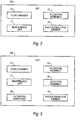
- FIG. 2 is a block diagram illustrating a liquid electrophotography printing apparatus according to an example.
- the LEP 200 includes a fluid chamber 21, a filtration assembly 22, a maintenance unit 17, and a photoconductive member 18.
- the photoconductive member 18 includes a surface configured to form a latent image thereon.
- the fluid chamber 21 is configured to store fluid having at least fluid particles, dissolved materials and a carrier liquid to be provided to the latent image of the photoconductive member 18 to form a fluid image corresponding thereto.
- the fluid chamber 21 may be a reservoir, ink tank, or the like.
- the carrier liquid in the liquid toner may include imaging oil such as Isopar, trademarked by Exxon Corporation, having a charge director compound dispersed therein.
- the fluid may be filtered to be used as a maintenance fluid on the photoconductive member 18.
- the filtered fluid may also be provided to an ink tank 59 ( FIG. 5 ) to dilute printing fluid stored therein to be supplied to the latent image of the photoconductive member 18 and subsequently to a substrate S in the form of images.
- the filtration assembly 22 is in fluid communication with the fluid chamber 21. Further, the filtration assembly 22 is configured to store filtration material to remove at least a portion of fluid particles and dissolved materials from the fluid from the fluid chamber 21 to form a filtered fluid.
- the fluid from the fluid chamber 21 is filtered outside of the fluid chamber 21. In other examples, the fluid from the fluid chamber 21 may be filtered therein.
- the filtration material may include sorption material such as silica gel, activated carbon, or the like, to remove at least a portion of the fluid particles and/or dissolved materials such as charge directors and contaminants by adsorption.
- at least one of the fluid particles and the dissolved materials may include charge directors, contaminants, and fluid residue.
- At least one of the fluid particles and the dissolved materials may include ink particles, charge directors, contaminants, and fluid residue.
- Fluid residue may include a portion of the fluid transferred to the latent image that remains on the photoconductive member 18 after the transfer of a fluid image from the photoconductive member 18 corresponding to the latent image.
- the maintenance unit 17 is configured to periodically apply the filtered fluid from the filtration assembly 22 to the photoconductive member 18 and to remove at least the filtered fluid from the photoconductive member 18.
- the maintenance unit 17 removes the filtered fluid and fluid residue from the photoconductive member 18.
- the maintenance unit 17 may be a cleaning and cooling unit. That is, the maintenance unit 17 may maintain the photoconductive member 18 by cleaning and cooling it through the periodic application of the filtered fluid thereto and removal of at least the filtered fluid therefrom.
- FIG. 3 is a block diagram illustrating a liquid electrophotography printing apparatus according to an example.
- a LEP 200 includes the fluid chamber 21, the maintenance unit 17, and the photoconductive member 18 as previously disclosed with respect to the LEP 200 illustrated in FIG. 2 .
- the LEP 300 as illustrated in FIG. 3 includes a filtration assembly 33 to automatically receive and store filtration material to remove at least a portion of fluid particles and dissolved materials by adsorption from the fluid from the fluid chamber 21 to form a filtered fluid.
- the LEP 300 also includes a detector assembly 35 and a filtration adder unit 36. The detector assembly 35 is configured to detect at least one fluid parameter of the fluid.
- the fluid parameter may include at least one of a predetermined electrical conductivity value such as low field conductivity.
- the low field conductivity may correspond to a dissolved contaminant concentration and/or an amount of charge directors (e.g., charge level) in the respective fluid.
- the filtration adder unit 36 is configured to automatically add a predetermined amount of the filtration material to the filtration assembly 33 based on the detection of the at least one parameter.
- the amount of filtration material to be added to the filtration assembly 33 corresponds to the detected parameter.
- a lookup table 56 FIG. 5
- the at least one parameter may be a low field conductivity value of 5 picosiemens and a corresponding predetermined amount of filtration material may be a dose of silica gel paste having thirty-five-forty-five wt% in Isopar.
- the silica gel may also be added in the form of a dry powder. Accordingly, in operation, small doses of the filtration material may be automatically inserted into the filtration assembly 33, for example, through an input port thereof to provide adsorption efficiency. Thus, an adjustable filtration material addition rate may be provided for different contamination rates.
- FIG. 4 is a block diagram of a liquid electrophotography printing apparatus according to an example.
- the LEP 400 includes the filtration adder unit 36 and the photoconductive member 18 as previously disclosed with respect to the LEP 300 illustrated in FIG. 3 .
- the LEP 400 includes a fluid chamber 41, a filtration assembly 43, a detector assembly 45 and a maintenance unit 48.
- the fluid chamber 41 may include a main compartment 41a and a waste compartment 41b.
- the main compartment 41a is configured to store the filtered fluid.
- the waste compartment 41b is configured to store the fluid and the fluid residue removed from the photoconductive member 18.
- the filtration assembly 43 may include a first filtration unit 43a and a second filtration unit 43b.
- the first filtration unit 43a is in fluid communication with the main compartment 41a of the fluid chamber 41.
- the first filtration unit 43a may include silica gel to filter the fluid in the main compartment 41a to form a first-filtered fluid and to provide the first-filtered fluid to the main compartment 41a.
- the silica gel of the first filtration unit 43a removes charge directors and dissolved materials from the fluid through adsorption.
- the second filtration unit 43b is in fluid communication with the waste compartment 41b and the main compartment 41a of the fluid chamber 41.
- the second filtration unit 43b may include a mesh screen to filter the fluid from the waste compartment 41b to form a second-filtered fluid and to provide the second-filtered fluid to the main compartment 41a.
- the mesh screen of the second filtration unit 43b removes contaminants and fluid residue from the respective fluid.
- the detector assembly 45 may be configured to detect at least one fluid parameter of the fluid and include a conductivity detector 45a to detect low field conductivity as previously disclosed with respect to FIG. 3 .
- the detector assembly 45 may also include a density detector 45b and a level detector 45c.
- the density of fluid may correspond to a dirtiness level of the respective fluid.
- the level detector 45c may include a level switch that switches on when a predetermined level of the respective fluid is achieved. For example, as illustrated in FIG. 5 , the density detector 45b detects and informs a user when a predetermined density value is achieved.
- the predetermined density value may correspond to a lower limit of an acceptable dirtiness level of the fluid.
- the level detector 45c detects and communicates to a fluid adder unit 59 that a predetermined fluid level has been achieved in the waste compartment 41b causing the fluid adder unit 59 to add supplemental fluid such as carrier fluid to the waste compartment 41b.
- the maintenance unit 48 includes a cooling unit 48a, an applicator unit 48b, and a removal unit 48c.
- the cooling unit 48a is configured to receive and cool the filtered fluid from the filtration assembly 43 to be applied to the photoconductive member 18.
- the cooling unit 48a provides the cooled filtered fluid, for example, received from the cooling unit 48a, to the applicator unit 48b.
- the cooling unit 48a may include a heat exchanger and/or a chamber having tubes transporting cold water, or the like, therethrough and in contact with the fluid to be cooled.
- the applicator unit 48b is configured to periodically apply the filtered fluid to the photoconductive member 18.
- the applicator unit 48b may include a pressure unit and a conduit to pressurize and direct fluid to be applied to the photoconductive member 18 therethrough.
- the pressure unit may include a pump such as a piston-based apparatus and/or a pressure-assisted can, or the like.
- the removal unit 48c is configured to subsequently remove at least the filtered fluid from the photoconductive member 18.
- the removal unit 48c may also remove fluid residue from the photoconductive member 18.
- the removal unit 48c may include a wiper, a catch basin and/or a conduit.
- the wiper may wipe the filtered fluid and fluid residue from the photoconductive member 18.
- the catch basin may catch the filtered fluid and fluid residue removed from the photoconductive member 18.
- the conduit may transport the filtered fluid and fluid residue from the photoconductive member 18 to the waste compartment 41b.
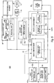
- FIG. 5 is a schematic diagram of a liquid electrophotography printing apparatus according to an example.
- the LEP 500 includes a fluid chamber 41, a detector assembly 45a, 45b and 45c, a filtration adder unit 36, a filtration assembly 43a and 43b, a maintenance unit 48, an ink tank 58, BIDs 13, a fluid adder unit 59, and a photoconductive member 18.
- the LEP 500 may also include pumps (not illustrated) to assist with fluid flow therein.
- the fluid chamber 41 includes a main compartment 41a and a waste compartment 41b.
- the detector assembly 45a, 45b and 45c includes a conductivity detector 45a to detect low field conductivity values of fluid, a density detector 45b to detect density of fluid, and a level detector 45c to detect a level of fluid as previously disclosed with respect to FIG. 4 .
- the filtration adder unit 36 may access and/or include a lookup table 56.
- the filtration assembly 43a and 43b includes a first filtration unit 43a and a second filtration unit 43b.
- the maintenance unit 48 includes a cooling unit 48a, an applicator unit 48b, and a removal unit 48c.
- the ink tank 58 supplies printing fluid to the BIDs 13 to be provided to a respective latent image on the photoconductive member 18 to form a fluid image thereon. Subsequently, the printing fluid is supplied to a substrate S in the form of images.
- filtered fluid from the main compartment 41a of the fluid chamber 41 is provided to the ink tank 58 to dilute the printing fluid.
- the filtered fluid from the main compartment 41a is also provided to the maintenance unit 48. That is, the cooling unit 48a cools the filtered fluid received from the main compartment 41a and provides the cooled filtered fluid to the applicator unit 48b.
- the applicator unit 48b periodically applies the cooled filtered fluid received from the cooling unit 48a to the photoconductive member 18.
- the removal unit 48c subsequently removes the filtered fluid and fluid residue from the photoconductive member 18 and provides it to the waste compartment 41b. Accordingly, the photoconductive member 18 is maintained through the cooling and cleaning of the photoconductive member 18 by the respective filtered fluid applied thereto.
- the waste compartment 41b stores the fluid and the fluid residue removed from the photoconductive member 18.
- the main compartment 41a stores filtered fluid filtered by the first filtration unit 43a and the second filtration unit 43b.
- the first filtration unit 43a forms a first-filtered fluid from the fluid from the main compartment 41a and provides the first-filtered fluid to the main compartment 41a. That is, silica gel in the first filtration unit 43a removes charge directors and dissolved materials from the fluid by adsorption.
- the filtration adder unit 36 periodically adds a predetermined amount of silica gel 55a to the first filtration unit 43a in response to a respective predetermined low field conductivity value of the fluid from the main compartment 41a detected and supplied by a conductivity detector 45a to the fluid adder unit 59.
- the low field conductivity of the fluid from the main compartment 41a is maintained above five picosiemens.
- the second filtration unit 43b forms a second-filtered fluid and provides the second-filtered fluid to the main compartment 41a.
- a second-filtered fluid is formed by a mesh screen 55b of the second filtration unit 43b removing fluid particles including contaminants and fluid residue from the fluid from the waste compartment 41b, for example, having a size greater than a size of the respective mesh openings of the mesh screen 55b.
- the level detector 45c detects and communicates to the fluid adder unit 59 that a predetermined fluid level has been achieved in the waste compartment 41b. In response to the predetermined fluid level being achieved, the fluid adder unit 59 adds supplemental fluid such as carrier fluid to the waste compartment 41b.
- the density detector 45b detects and informs a user when a predetermined density value is achieved.
- the predetermined density value may correspond to a lower limit of an acceptable dirtiness level of the fluid. Accordingly, the user may be alerted to change the second filtration unit 43b prior to the dirtiness level of the fluid achieving an unacceptable level.
- FIG. 6 is a flowchart illustrating a method of maintaining a photoconductive member of a liquid electrophotography printing apparatus according to an example.
- a fluid having at least fluid particles, dissolved materials and a carrier liquid is stored in a fluid chamber.
- at least a portion of the fluid particles and the dissolved materials are removed from the fluid through adsorption by filtration material disposed within a filtration assembly to form a filtered fluid.
- the photoconductive member is maintained by periodically applying the filtered fluid to the photoconductive member and removing at least the filtered fluid therefrom.
- maintaining the photoconductive member may include cooling the filtered fluid to be applied to the photoconductive member.
- Maintenance of the photoconductive member may also include cleaning and cooling the photoconductive member through the periodic application of the filtered fluid thereto and removal of the filtered fluid therefrom.
- the method may also include detecting at least one fluid parameter, and automatically adding a predetermined amount of filtration material to the filtration assembly based on the detection of the at least one fluid parameter.
Landscapes
- Physics & Mathematics (AREA)
- General Physics & Mathematics (AREA)
- Wet Developing In Electrophotography (AREA)
- Cleaning In Electrography (AREA)
Description
- Liquid electrophotography printing apparatus includes providing fluid such as liquid toner to fluid applicators such as binary ink developers. The fluid applicators provide charged liquid toner to a latent image on a photoconductive member to form fluid images. The photoconductive member transfers the fluid images onto an image transfer member and/or substrate. Generally, the liquid toner includes charge directors to electrically charge the liquid toner.
-
WO-A-01/92968 -
US-A-2 991 709 discloses an electrophotographic apparatus wherein a developing liquid containing toner particles is applied to an electrophotographic photosensitive member, in a development process. The apparatus comprises a container for recovering the developing liquid which has been used in the development process, means for stirring the developing liquid within said container, filter means disposed at such a position that liquid flow caused by said stirring means impinges thereon. -
GB-A-1 244 901
the form of a liquid absorbing soft body comprising internal pores or recesses sweeping the recording surface in a direction opposite to the movement of the recording surface. The apparatus further comprises a nozzle for supplying a liquid cleaner to the wiper, a vessel for storing the liquid cleaner discharged from the nozzle and in which an amount of the toner deposited on the wiper is dispersed, a pump for circulating the liquid cleaner to supply it to the nozzle, and a filter for removing the toner dispersed in the liquid cleaner. - Non-limiting examples of the present disclosure are described in the following description, read with reference to the figures attached hereto and do not limit the scope of the claims. In the figures, identical and similar structures, elements or parts thereof that appear in more than one figure are generally labeled with the same or similar references in the figures in which they appear. Dimensions of components and features illustrated in the figures are chosen primarily for convenience and clarity of presentation and are not necessarily to scale. Referring to the attached figures:
-
FIG. 1 is a schematic view illustrating a liquid electrophotography printing apparatus according to an example. -
FIG. 2 is a block diagram illustrating a liquid electrophotography printing apparatus according to an example. -
FIG. 3 is a block diagram illustrating a liquid electrophotography printing apparatus according to an example. -
FIG. 4 is a block diagram of a liquid electrophotography printing apparatus according to an example. -
FIG. 5 is a schematic diagram of a liquid electrophotography printing apparatus according to an example. -
FIG. 6 is a flowchart illustrating a method of maintaining a photoconductive member of a liquid electrophotography printing apparatus according to an example. - In the following detailed description, reference is made to the accompanying drawings which form a part hereof, and in which is depicted by way of illustration specific examples in which the present disclosure may be practiced. It is to be understood that other examples may be utilized and structural or logical changes may be made without departing from the scope of the present disclosure. The following detailed description, therefore, is not to be taken in a limiting sense, and the scope of the present disclosure is defined by the appended claims.
- Liquid electrophotography printing apparatus (LEP) provides fluid such as liquid toner including charge directors, dissolved materials, and carrier fluid to fluid applicators such as binary ink developers (BIDs). A fluid chamber receives the charge directors, dissolved materials, and carrier fluid forming the liquid toner. The liquid toner is charged and is provided to a latent image on a photoconductive member such as a photo imaging member (PIP) to form a fluid image, for example, by BIDs. The photoconductive member, in turn, provides the image to an image transfer member such as an image transfer blanket. The image transfer blanket transfers the image onto a substrate such as print media. Degradation of the photoconductive member and image quality may occur over time, however, based on an accumulation of fluid particles and/or dissolved materials in the fluid such as charge directors, contaminants and fluid residue. That is, such accumulation may scratch and/or undesirably remain on the photoconductive member, increase old pip stickiness syndrome (OPS) due to an overabundance of charge directors, and negatively contribute to printing side effects such as electrical fatigue, or the like.
- In examples of the present disclosure, a LEP includes a filtration assembly configured to store filtration material to remove fluid particles and dissolved materials from a fluid from the fluid chamber to form a filtered fluid. For example, such fluid particles and dissolved materials may be removed by adsorption to remove charge directors and contaminants therein which may have otherwise passed through a mesh screen while reducing its impedance on desirable soluble components of the respective fluid. The LEP also includes a maintenance unit configured to periodically apply the filtered fluid from the filtration assembly to the photoconductive member and to remove at least the filtered fluid from the photoconductive member. Such maintenance of the photoconductive member and use of the filtered fluid thereon, increases the lifespan of the photoconductive member and extends the period of time in which high-quality images are produced.
- In an example, the LEP also includes a detector assembly configured to detect at least one fluid parameter of the fluid and a filtration adder unit configured to automatically add a predetermined amount of the filtration material to the filtration assembly based on the detection of the at least one fluid parameter. The automatic addition of the predetermined amount of the filtration material based on the at least one fluid parameter enables effective removal of the unwanted fluid particles and dissolved materials from the fluid to form filtered fluid to be used to maintain the photoconductive member. That is, an appropriate amount of the filtration material inserted in small doses during operation of the LEP effectively increases the adsorption of the filtration assembly. Accordingly, degradation of the photoconductive member and image quality is reduced.
-
FIG. 1 is a schematic view illustrating a liquid electrophotography printing apparatus according to an example. Referring toFIG. 1 , a liquid electrophotography printing apparatus (LEP) 100 includes animage forming unit 12 that receives a substrate S such as a print media from aninput unit 14a and outputs the substrate S to anoutput unit 14b. Theimage forming unit 12 includes aphotoconductive member 18 on which images can be formed. Thephotoconductive member 18 may be charged with a suitable charger (not illustrated) such as a charge roller. Portions of the outer surface of thephotoconductive member 18 that correspond to features of the image can be selectively discharged by alaser writing unit 16 to form an electrostatic and/or latent image thereon. - Referring to
FIG. 1 , the LEP 100 also includes afluid delivery system 11 to supply fluid such as liquid toner, for example, Electrolnk, trademarked by Hewlett-Packard Company, to fluid applicators such asBIDs 13 and fluid to amaintenance unit 17 to be used to maintain thephotoconductive member 18. TheBIDs 13 apply the fluid to the electrostatic and/or latent image to form a fluid image on thephotoconductive member 18 to be transferred to an intermediate transfer member (ITM) 15. TheITM 15 is configured to receive the fluid image from thephotoconductive member 18, heat the fluid image, and transfer the fluid image to the substrate S. During the transfer from theITM 15 to the substrate S, the substrate S is pinched between theITM 15 and animpression member 19. Once the fluid image has been transferred to the substrate S, the substrate S can be transported to theoutput unit 14b. -
FIG. 2 is a block diagram illustrating a liquid electrophotography printing apparatus according to an example. Referring toFIG. 2 , in the present example, theLEP 200 includes afluid chamber 21, afiltration assembly 22, amaintenance unit 17, and aphotoconductive member 18. Thephotoconductive member 18 includes a surface configured to form a latent image thereon. Thefluid chamber 21 is configured to store fluid having at least fluid particles, dissolved materials and a carrier liquid to be provided to the latent image of thephotoconductive member 18 to form a fluid image corresponding thereto. In examples, thefluid chamber 21 may be a reservoir, ink tank, or the like. The carrier liquid in the liquid toner may include imaging oil such as Isopar, trademarked by Exxon Corporation, having a charge director compound dispersed therein. In the present example, the fluid may be filtered to be used as a maintenance fluid on thephotoconductive member 18. In another example, the filtered fluid may also be provided to an ink tank 59 (FIG. 5 ) to dilute printing fluid stored therein to be supplied to the latent image of thephotoconductive member 18 and subsequently to a substrate S in the form of images. - As illustrated in
FIG. 2 , thefiltration assembly 22 is in fluid communication with thefluid chamber 21. Further, thefiltration assembly 22 is configured to store filtration material to remove at least a portion of fluid particles and dissolved materials from the fluid from thefluid chamber 21 to form a filtered fluid. In the present example, the fluid from thefluid chamber 21 is filtered outside of thefluid chamber 21. In other examples, the fluid from thefluid chamber 21 may be filtered therein. In an example, the filtration material may include sorption material such as silica gel, activated carbon, or the like, to remove at least a portion of the fluid particles and/or dissolved materials such as charge directors and contaminants by adsorption. In an example, at least one of the fluid particles and the dissolved materials may include charge directors, contaminants, and fluid residue. In examples, at least one of the fluid particles and the dissolved materials may include ink particles, charge directors, contaminants, and fluid residue. Fluid residue may include a portion of the fluid transferred to the latent image that remains on thephotoconductive member 18 after the transfer of a fluid image from thephotoconductive member 18 corresponding to the latent image. - Referring to
FIG. 2 , themaintenance unit 17 is configured to periodically apply the filtered fluid from thefiltration assembly 22 to thephotoconductive member 18 and to remove at least the filtered fluid from thephotoconductive member 18. In an example, themaintenance unit 17 removes the filtered fluid and fluid residue from thephotoconductive member 18. Themaintenance unit 17 may be a cleaning and cooling unit. That is, themaintenance unit 17 may maintain thephotoconductive member 18 by cleaning and cooling it through the periodic application of the filtered fluid thereto and removal of at least the filtered fluid therefrom. -
FIG. 3 is a block diagram illustrating a liquid electrophotography printing apparatus according to an example. Referring toFIG. 3 , in the present example, aLEP 200 includes thefluid chamber 21, themaintenance unit 17, and thephotoconductive member 18 as previously disclosed with respect to theLEP 200 illustrated inFIG. 2 . In addition, in the present example, theLEP 300 as illustrated inFIG. 3 includes afiltration assembly 33 to automatically receive and store filtration material to remove at least a portion of fluid particles and dissolved materials by adsorption from the fluid from thefluid chamber 21 to form a filtered fluid. Referring toFIG. 3 , theLEP 300 also includes adetector assembly 35 and afiltration adder unit 36. Thedetector assembly 35 is configured to detect at least one fluid parameter of the fluid. In an example, the fluid parameter may include at least one of a predetermined electrical conductivity value such as low field conductivity. The low field conductivity may correspond to a dissolved contaminant concentration and/or an amount of charge directors (e.g., charge level) in the respective fluid. - Referring to
FIG. 3 , thefiltration adder unit 36 is configured to automatically add a predetermined amount of the filtration material to thefiltration assembly 33 based on the detection of the at least one parameter. The amount of filtration material to be added to thefiltration assembly 33 corresponds to the detected parameter. For example, for a respective fluid, a lookup table 56 (FIG. 5 ) may be accessed by theLEP 300 to indicate the respective predetermined amount of filtration material to be added for a corresponding parameter value. In an example, the at least one parameter may be a low field conductivity value of 5 picosiemens and a corresponding predetermined amount of filtration material may be a dose of silica gel paste having thirty-five-forty-five wt% in Isopar. In other examples, the silica gel may also be added in the form of a dry powder. Accordingly, in operation, small doses of the filtration material may be automatically inserted into thefiltration assembly 33, for example, through an input port thereof to provide adsorption efficiency. Thus, an adjustable filtration material addition rate may be provided for different contamination rates. -
FIG. 4 is a block diagram of a liquid electrophotography printing apparatus according to an example. Referring toFIG. 4 , in the present example, the LEP 400 includes thefiltration adder unit 36 and thephotoconductive member 18 as previously disclosed with respect to theLEP 300 illustrated inFIG. 3 . In addition, as illustrated inFIG. 4 , the LEP 400 includes afluid chamber 41, afiltration assembly 43, adetector assembly 45 and amaintenance unit 48. Thefluid chamber 41 may include amain compartment 41a and awaste compartment 41b. Themain compartment 41a is configured to store the filtered fluid. Thewaste compartment 41b is configured to store the fluid and the fluid residue removed from thephotoconductive member 18. - Referring to
FIG. 4 , thefiltration assembly 43 may include afirst filtration unit 43a and asecond filtration unit 43b. Thefirst filtration unit 43a is in fluid communication with themain compartment 41a of thefluid chamber 41. Thefirst filtration unit 43a may include silica gel to filter the fluid in themain compartment 41a to form a first-filtered fluid and to provide the first-filtered fluid to themain compartment 41a. In the present example, the silica gel of thefirst filtration unit 43a removes charge directors and dissolved materials from the fluid through adsorption. Thesecond filtration unit 43b is in fluid communication with thewaste compartment 41b and themain compartment 41a of thefluid chamber 41. Thesecond filtration unit 43b may include a mesh screen to filter the fluid from thewaste compartment 41b to form a second-filtered fluid and to provide the second-filtered fluid to themain compartment 41a. In the present example, the mesh screen of thesecond filtration unit 43b removes contaminants and fluid residue from the respective fluid. - Referring to
FIG. 4 , thedetector assembly 45 may be configured to detect at least one fluid parameter of the fluid and include aconductivity detector 45a to detect low field conductivity as previously disclosed with respect toFIG. 3 . Referring toFIG. 4 , thedetector assembly 45 may also include adensity detector 45b and alevel detector 45c. The density of fluid may correspond to a dirtiness level of the respective fluid. Thelevel detector 45c may include a level switch that switches on when a predetermined level of the respective fluid is achieved. For example, as illustrated inFIG. 5 , thedensity detector 45b detects and informs a user when a predetermined density value is achieved. The predetermined density value may correspond to a lower limit of an acceptable dirtiness level of the fluid. Accordingly, the user may be alerted to change thesecond filtration unit 43b prior to the dirtiness level of the fluid achieving an unacceptable level. Thelevel detector 45c detects and communicates to afluid adder unit 59 that a predetermined fluid level has been achieved in thewaste compartment 41b causing thefluid adder unit 59 to add supplemental fluid such as carrier fluid to thewaste compartment 41b. - Referring to
FIG. 4 , in the present example, themaintenance unit 48 includes acooling unit 48a, anapplicator unit 48b, and aremoval unit 48c. Thecooling unit 48a is configured to receive and cool the filtered fluid from thefiltration assembly 43 to be applied to thephotoconductive member 18. In an example, thecooling unit 48a provides the cooled filtered fluid, for example, received from thecooling unit 48a, to theapplicator unit 48b. Thecooling unit 48a may include a heat exchanger and/or a chamber having tubes transporting cold water, or the like, therethrough and in contact with the fluid to be cooled. Theapplicator unit 48b is configured to periodically apply the filtered fluid to thephotoconductive member 18. Theapplicator unit 48b may include a pressure unit and a conduit to pressurize and direct fluid to be applied to thephotoconductive member 18 therethrough. For example, the pressure unit may include a pump such as a piston-based apparatus and/or a pressure-assisted can, or the like. - Referring to
FIG. 4 , theremoval unit 48c is configured to subsequently remove at least the filtered fluid from thephotoconductive member 18. In an example, theremoval unit 48c may also remove fluid residue from thephotoconductive member 18. Theremoval unit 48c may include a wiper, a catch basin and/or a conduit. The wiper may wipe the filtered fluid and fluid residue from thephotoconductive member 18. The catch basin may catch the filtered fluid and fluid residue removed from thephotoconductive member 18. The conduit may transport the filtered fluid and fluid residue from thephotoconductive member 18 to thewaste compartment 41b. -
FIG. 5 is a schematic diagram of a liquid electrophotography printing apparatus according to an example. Referring toFIG. 5 , in the present example, theLEP 500 includes afluid chamber 41, adetector assembly filtration adder unit 36, afiltration assembly maintenance unit 48, anink tank 58,BIDs 13, afluid adder unit 59, and aphotoconductive member 18. TheLEP 500 may also include pumps (not illustrated) to assist with fluid flow therein. Thefluid chamber 41 includes amain compartment 41a and awaste compartment 41b. Thedetector assembly conductivity detector 45a to detect low field conductivity values of fluid, adensity detector 45b to detect density of fluid, and alevel detector 45c to detect a level of fluid as previously disclosed with respect toFIG. 4 . Thefiltration adder unit 36 may access and/or include a lookup table 56. Thefiltration assembly first filtration unit 43a and asecond filtration unit 43b. Themaintenance unit 48 includes acooling unit 48a, anapplicator unit 48b, and aremoval unit 48c. - Referring to
FIG. 5 , in operation, theink tank 58 supplies printing fluid to theBIDs 13 to be provided to a respective latent image on thephotoconductive member 18 to form a fluid image thereon. Subsequently, the printing fluid is supplied to a substrate S in the form of images. When necessary, filtered fluid from themain compartment 41a of thefluid chamber 41 is provided to theink tank 58 to dilute the printing fluid. The filtered fluid from themain compartment 41a is also provided to themaintenance unit 48. That is, thecooling unit 48a cools the filtered fluid received from themain compartment 41a and provides the cooled filtered fluid to theapplicator unit 48b. Theapplicator unit 48b periodically applies the cooled filtered fluid received from thecooling unit 48a to thephotoconductive member 18. Theremoval unit 48c subsequently removes the filtered fluid and fluid residue from thephotoconductive member 18 and provides it to thewaste compartment 41b. Accordingly, thephotoconductive member 18 is maintained through the cooling and cleaning of thephotoconductive member 18 by the respective filtered fluid applied thereto. - As illustrated in
FIG. 5 , thewaste compartment 41b stores the fluid and the fluid residue removed from thephotoconductive member 18. Themain compartment 41a stores filtered fluid filtered by thefirst filtration unit 43a and thesecond filtration unit 43b. Thefirst filtration unit 43a forms a first-filtered fluid from the fluid from themain compartment 41a and provides the first-filtered fluid to themain compartment 41a. That is, silica gel in thefirst filtration unit 43a removes charge directors and dissolved materials from the fluid by adsorption. Thefiltration adder unit 36 periodically adds a predetermined amount ofsilica gel 55a to thefirst filtration unit 43a in response to a respective predetermined low field conductivity value of the fluid from themain compartment 41a detected and supplied by aconductivity detector 45a to thefluid adder unit 59. In an example, the low field conductivity of the fluid from themain compartment 41a is maintained above five picosiemens. - Referring to
FIG. 5 , thesecond filtration unit 43b forms a second-filtered fluid and provides the second-filtered fluid to themain compartment 41a. A second-filtered fluid is formed by amesh screen 55b of thesecond filtration unit 43b removing fluid particles including contaminants and fluid residue from the fluid from thewaste compartment 41b, for example, having a size greater than a size of the respective mesh openings of themesh screen 55b. Thelevel detector 45c detects and communicates to thefluid adder unit 59 that a predetermined fluid level has been achieved in thewaste compartment 41b. In response to the predetermined fluid level being achieved, thefluid adder unit 59 adds supplemental fluid such as carrier fluid to thewaste compartment 41b. Thedensity detector 45b detects and informs a user when a predetermined density value is achieved. The predetermined density value may correspond to a lower limit of an acceptable dirtiness level of the fluid. Accordingly, the user may be alerted to change thesecond filtration unit 43b prior to the dirtiness level of the fluid achieving an unacceptable level. -
FIG. 6 is a flowchart illustrating a method of maintaining a photoconductive member of a liquid electrophotography printing apparatus according to an example. Referring toFIG. 6 , in block S610, a fluid having at least fluid particles, dissolved materials and a carrier liquid is stored in a fluid chamber. In block S620, at least a portion of the fluid particles and the dissolved materials are removed from the fluid through adsorption by filtration material disposed within a filtration assembly to form a filtered fluid. In block S630, the photoconductive member is maintained by periodically applying the filtered fluid to the photoconductive member and removing at least the filtered fluid therefrom. In an example, maintaining the photoconductive member may include cooling the filtered fluid to be applied to the photoconductive member. Maintenance of the photoconductive member may also include cleaning and cooling the photoconductive member through the periodic application of the filtered fluid thereto and removal of the filtered fluid therefrom. In an example, the method may also include detecting at least one fluid parameter, and automatically adding a predetermined amount of filtration material to the filtration assembly based on the detection of the at least one fluid parameter. - The present disclosure has been described using non-limiting detailed descriptions of examples thereof and is not intended to limit the scope of the present disclosure. It should be understood that features and/or operations described with respect to one example may be used with other examples and that not all examples of the present disclosure have all of the features and/or operations illustrated in a particular figure or described with respect to one of the examples. Variations of examples described will occur to persons of the art. Furthermore, the terms "comprise," "include," "have" and their conjugates, shall mean, when used in the present disclosure and/or claims, "including but not necessarily limited to."
- It is noted that some of the above described examples may include structure, acts or details of structures and acts that may not be essential to the present disclosure and are intended to be exemplary. Structure and acts described herein are replaceable by equivalents, which perform the same function, even if the structure or acts are different, as known in the art. Therefore, the scope of the present disclosure is limited only by the elements and limitations as used in the claims.
Claims (15)
- A liquid electrophotography printing apparatus (LEP) (100 - 500), comprising:a photoconductive member (18) having a surface configured to form a latent image thereon;fluid applicators (13), the fluid applicators (13) being configured to apply fluid to the latent image to form a fluid image on the photoconductive member (18);a fluid chamber (21, 41) configured to store the fluid, the fluid having at least fluid particles, dissolved materials and a carrier liquid;a filtration assembly (22, 33, 43) in fluid communication with the fluid chamber (21, 41), the filtration assembly (22, 33, 43) configured to store filtration material to remove at least a portion of the fluid particles and the dissolved materials from the fluid from the fluid chamber (21, 41) to form a filtered fluid; anda maintenance unit (17, 48) different from the fluid applicators (13), the maintenance unit (17, 48) being configured to periodically apply the filtered fluid from the filtration assembly (22, 33, 43) to the photoconductive member (18) and to remove at least the filtered fluid from the photoconductive member (18).
- The LEP according to claim 1, wherein the filtration material comprises at least one of silica gel and activated carbon to remove at least a portion of the fluid particles and the dissolved materials by adsorption.
- The LEP according to claim 1, wherein the maintenance unit (48) comprises:a cooling unit (48a) configured to receive and cool the filtered fluid from the filtration assembly (43) to be applied to the photoconductive member (18);an applicator unit (48b) configured to periodically apply the filtered fluid to the photoconductive member (18); anda removal unit (48c) configured to subsequently remove at least the filtered fluid from the photoconductive member (18).
- The LEP according to claim 3, wherein the maintenance unit (43) configured to maintain the photoconductive member (18) is configured to:
clean and cool the photoconductive member (18) through the periodic application of the filtered fluid thereto and to remove at least the filtered fluid therefrom. - The LEP according to claim 3 being configured such that fluid residue adheres to the photoconductive member (18) after a fluid image corresponding to the respective latent image is transferred therefrom.
- The LEP according to claim 5, wherein the fluid chamber (41) comprises:a waste compartment (41b) configured to store the fluid and the fluid residue removed from the photoconductive member (18); anda main compartment (41a) configured to store the filtered fluid.
- The LEP according to claim 6, wherein at least one of the fluid particles and the dissolved materials comprise ink particles, charge directors, contaminants and the fluid residue.
- The LEP according to claim 1, further comprising:a detector assembly (35, 45) configured to detect at least one fluid parameter of the fluid; anda filtration adder unit (36) configured to automatically add a predetermined amount of the filtration material to the filtration assembly (22, 33, 43) based on the detection of the at least one fluid parameter.
- The LEP according to claim 8, wherein the fluid parameter comprises a predetermined low field conductivity value.
- The LEP according to claim 3, wherein the filtration assembly (43) comprises:a first filtration unit (43a) in fluid communication with the main compartment (41a) of the fluid chamber (21, 41), the first filtration unit (43a) including the silica gel to filter the fluid from the main compartment (41a) to form a first-filtered fluid and to provide the first-filtered fluid to the main compartment (41a); anda second filtration unit (43b) in fluid communication with the waste compartment (41b) and the main compartment (41a) of the fluid chamber (21, 41), the second filtration unit (43b) including a mesh screen (55b) to filter the fluid from the waste compartment (41b) to form a second-filtered fluid and to provide the second-filtered fluid to the main compartment (41a).
- The LEP according to claim 1, wherein the photoconductive member (18) comprises a photo imaging member and the fluid comprises a liquid toner.
- The liquid electrophotography printing apparatus according to claim 1,
wherein the filtration assembly (22, 33, 43) is configured to automatically receive and store the filtration material to remove at least a portion of the fluid particles and the dissolved materials by adsorption from the fluid of the fluid chamber (21, 41) to form the filtered fluid;
wherein the LEP further comprises:a detector assembly (35, 45) configured to detect at least one fluid parameter of the fluid having at least fluid particles, dissolved materials and the carrier liquid; anda filtration adder unit (36) configured to automatically add a predetermined amount of the filtration material to the filtration assembly (22, 33, 43) based on the detection of the at least one parameter. - A method of maintaining a photoconductive member (18) of a liquid electrophotography printing apparatus (LEP), the method comprising:storing (S610) a fluid having at least fluid particles, dissolved materials and a carrier liquid in a fluid chamber (21, 41);removing (S620) at least a portion of the fluid particles and the dissolved materials from the fluid through adsorption by filtration material disposed within a filtration assembly (22, 33, 43) to form a filtered fluid; andmaintaining (S630) the photoconductive member (18) by periodically applying the filtered fluid to the photoconductive member (18) and removing the filtered fluid and fluid residue therefrom by means of a maintenance unit (17, 48) different from fluid applicators (13), the fluid applicators (13) being configured to apply fluid to a latent image to form a fluid image on the photoconductive member (18).
- The method according to claim 13, wherein the maintaining the photoconductive member (18) further comprises:cooling the filtered fluid to be applied to the photoconductive member (18); andcleaning and cooling the photoconductive member (18) through the periodic application of the filtered fluid thereto and removal of the filtered fluid therefrom.
- The method according to claim 14, further comprising:detecting at least one fluid parameter; andautomatically adding a predetermined amount of filtration material to the filtration assembly (22, 33, 43) based on the detection of the at least one fluid parameter.
Applications Claiming Priority (1)
| Application Number | Priority Date | Filing Date | Title |
|---|---|---|---|
| PCT/EP2011/050815 WO2012097877A1 (en) | 2011-01-21 | 2011-01-21 | Liquid electrophotography printing apparatus and methods thereof |
Publications (2)
| Publication Number | Publication Date |
|---|---|
| EP2666060A1 EP2666060A1 (en) | 2013-11-27 |
| EP2666060B1 true EP2666060B1 (en) | 2019-05-01 |
Family
ID=44625024
Family Applications (1)
| Application Number | Title | Priority Date | Filing Date |
|---|---|---|---|
| EP11700934.0A Active EP2666060B1 (en) | 2011-01-21 | 2011-01-21 | Liquid electrophotography printing apparatus and methods thereof |
Country Status (3)
| Country | Link |
|---|---|
| US (2) | US9037046B2 (en) |
| EP (1) | EP2666060B1 (en) |
| WO (1) | WO2012097877A1 (en) |
Families Citing this family (5)
| Publication number | Priority date | Publication date | Assignee | Title |
|---|---|---|---|---|
| WO2012097877A1 (en) * | 2011-01-21 | 2012-07-26 | Hewlett-Packard Indigo B.V. | Liquid electrophotography printing apparatus and methods thereof |
| EP3230801B1 (en) * | 2015-04-01 | 2022-03-09 | HP Indigo B.V. | Reducing contamination |
| EP3488296B1 (en) | 2016-07-20 | 2021-02-17 | HP Indigo B.V. | Operating a liquid electrophotographic printer |
| US11256196B2 (en) | 2018-08-22 | 2022-02-22 | Hewlett-Packard Development Company, L.P. | Filtering printing fluid |
| US11852996B1 (en) * | 2022-10-24 | 2023-12-26 | Hewlett-Packard Development Company, L.P. | Uncharged ink supply for electrical fatigue in liquid electrophotography printing |
Citations (1)
| Publication number | Priority date | Publication date | Assignee | Title |
|---|---|---|---|---|
| US6011943A (en) * | 1998-02-27 | 2000-01-04 | Samsung Electronics Co., Ltd. | Ink delivery system for liquid electrophotographic printer |
Family Cites Families (14)
| Publication number | Priority date | Publication date | Assignee | Title |
|---|---|---|---|---|
| US3224587A (en) * | 1957-12-04 | 1965-12-21 | Industrial Filter Pump Mfg Co | Filtration apparatus utilizing unrollable filter medium |
| GB1244901A (en) * | 1968-01-18 | 1971-09-02 | Tokyo Shibaura Electric Co | An electrostatic recording apparatus |
| US3991709A (en) | 1971-02-09 | 1976-11-16 | Canon Kabushiki Kaisha | Regenerating device for developing liquid |
| US4640605A (en) * | 1984-10-02 | 1987-02-03 | Ricoh Company, Ltd. | Apparatus for forming multicolor electrophotographic images through wet-type developing process |
| DE10027203A1 (en) * | 2000-05-31 | 2001-12-20 | Oce Printing Systems Gmbh | Device and method for cleaning and regenerating an image carrier in electrographic printing or copying using liquid colorants |
| JP2002214825A (en) | 2001-01-17 | 2002-07-31 | Fuji Xerox Co Ltd | Electrophotographic toner, electrophotographic developer and image forming method |
| JP4103556B2 (en) | 2002-11-12 | 2008-06-18 | 富士ゼロックス株式会社 | Electrostatic charge image dry toner composition, method for producing the same, developer, and image forming method |
| KR100667779B1 (en) | 2004-11-22 | 2007-01-12 | 삼성전자주식회사 | Developer for electrophotography |
| DE602005017945D1 (en) | 2005-06-06 | 2010-01-07 | Hewlett Packard Development Co | LIQUID TONER AND A METHOD FOR CHARGING TONER PARTICLES INFLUENCED |
| KR20080049062A (en) * | 2005-09-28 | 2008-06-03 | 미쓰비시 가가꾸 가부시키가이샤 | An electrophotographic photosensitive member, an image forming apparatus using the same, and a cartridge |
| US20090311614A1 (en) | 2006-05-10 | 2009-12-17 | Hewlett-Packard Development Company, L.P. | Charge Director for Liquid Toner |
| US8792796B2 (en) * | 2007-04-30 | 2014-07-29 | Hewlett-Packard Development Company, L.P. | Development monitoring method and system |
| US8041275B2 (en) * | 2008-10-30 | 2011-10-18 | Hewlett-Packard Development Company, L.P. | Release layer |
| WO2012097877A1 (en) * | 2011-01-21 | 2012-07-26 | Hewlett-Packard Indigo B.V. | Liquid electrophotography printing apparatus and methods thereof |
-
2011
- 2011-01-21 WO PCT/EP2011/050815 patent/WO2012097877A1/en not_active Ceased
- 2011-01-21 EP EP11700934.0A patent/EP2666060B1/en active Active
- 2011-01-21 US US13/978,922 patent/US9037046B2/en active Active
-
2015
- 2015-03-20 US US14/664,446 patent/US9465323B2/en not_active Expired - Fee Related
Patent Citations (1)
| Publication number | Priority date | Publication date | Assignee | Title |
|---|---|---|---|---|
| US6011943A (en) * | 1998-02-27 | 2000-01-04 | Samsung Electronics Co., Ltd. | Ink delivery system for liquid electrophotographic printer |
Also Published As
| Publication number | Publication date |
|---|---|
| WO2012097877A1 (en) | 2012-07-26 |
| US9037046B2 (en) | 2015-05-19 |
| US9465323B2 (en) | 2016-10-11 |
| EP2666060A1 (en) | 2013-11-27 |
| US20150198912A1 (en) | 2015-07-16 |
| US20140105648A1 (en) | 2014-04-17 |
Similar Documents
| Publication | Publication Date | Title |
|---|---|---|
| EP1574915B1 (en) | Apparatus and method for cleaning an image transfer device | |
| US7599653B2 (en) | Image forming apparatus | |
| JP5620591B2 (en) | Printing system using ink with high solids content | |
| US9465323B2 (en) | Liquid electrophotography printing apparatus and methods thereof | |
| US7809307B2 (en) | Image forming apparatus with cleaner having member in contact with a surface of an image carrier | |
| JPH0915981A (en) | Excess developer removing device | |
| US8224210B2 (en) | Image developer for presenting ink to a photoconductor | |
| CN101008817A (en) | Image forming apparatus | |
| US6308034B1 (en) | Wet-type electrophotography apparatus, using non-volatile, high viscosity, high concentration liquid toner | |
| US10908520B2 (en) | Method and apparatus for reducing contamination in liquid electrophotographic printing | |
| US8583021B2 (en) | Image forming apparatus including sponge applicator units to sequentially contact a photoconductive member | |
| US20050158082A1 (en) | Liquid developing device | |
| US8437679B2 (en) | System and method for recycling cleaning liquid in a printer | |
| EP2473882B1 (en) | Liquid marking agent development assemblies, hard imaging devices, and liquid marking agent hard imaging methods | |
| US8983321B2 (en) | Fluid delivery system and method thereof | |
| JP4230247B2 (en) | Image forming apparatus | |
| US7756449B2 (en) | Electrophotographic printing apparatus and methods in which carrier medium is extracted from unused ink | |
| JP2009025606A (en) | Image forming apparatus | |
| JP2009025605A (en) | Image forming apparatus | |
| JP2004212531A (en) | Image forming apparatus | |
| JP2019060977A (en) | Image forming apparatus |
Legal Events
| Date | Code | Title | Description |
|---|---|---|---|
| PUAI | Public reference made under article 153(3) epc to a published international application that has entered the european phase |
Free format text: ORIGINAL CODE: 0009012 |
|
| 17P | Request for examination filed |
Effective date: 20130718 |
|
| AK | Designated contracting states |
Kind code of ref document: A1 Designated state(s): AL AT BE BG CH CY CZ DE DK EE ES FI FR GB GR HR HU IE IS IT LI LT LU LV MC MK MT NL NO PL PT RO RS SE SI SK SM TR |
|
| DAX | Request for extension of the european patent (deleted) | ||
| STAA | Information on the status of an ep patent application or granted ep patent |
Free format text: STATUS: EXAMINATION IS IN PROGRESS |
|
| RAP1 | Party data changed (applicant data changed or rights of an application transferred) |
Owner name: HP INDIGO B.V. |
|
| 17Q | First examination report despatched |
Effective date: 20171130 |
|
| GRAP | Despatch of communication of intention to grant a patent |
Free format text: ORIGINAL CODE: EPIDOSNIGR1 |
|
| STAA | Information on the status of an ep patent application or granted ep patent |
Free format text: STATUS: GRANT OF PATENT IS INTENDED |
|
| INTG | Intention to grant announced |
Effective date: 20181123 |
|
| GRAS | Grant fee paid |
Free format text: ORIGINAL CODE: EPIDOSNIGR3 |
|
| GRAA | (expected) grant |
Free format text: ORIGINAL CODE: 0009210 |
|
| STAA | Information on the status of an ep patent application or granted ep patent |
Free format text: STATUS: THE PATENT HAS BEEN GRANTED |
|
| AK | Designated contracting states |
Kind code of ref document: B1 Designated state(s): AL AT BE BG CH CY CZ DE DK EE ES FI FR GB GR HR HU IE IS IT LI LT LU LV MC MK MT NL NO PL PT RO RS SE SI SK SM TR |
|
| REG | Reference to a national code |
Ref country code: GB Ref legal event code: FG4D |
|
| REG | Reference to a national code |
Ref country code: AT Ref legal event code: REF Ref document number: 1127744 Country of ref document: AT Kind code of ref document: T Effective date: 20190515 Ref country code: CH Ref legal event code: EP |
|
| REG | Reference to a national code |
Ref country code: DE Ref legal event code: R096 Ref document number: 602011058472 Country of ref document: DE |
|
| REG | Reference to a national code |
Ref country code: IE Ref legal event code: FG4D |
|
| REG | Reference to a national code |
Ref country code: NL Ref legal event code: MP Effective date: 20190501 |
|
| REG | Reference to a national code |
Ref country code: LT Ref legal event code: MG4D |
|
| PG25 | Lapsed in a contracting state [announced via postgrant information from national office to epo] |
Ref country code: ES Free format text: LAPSE BECAUSE OF FAILURE TO SUBMIT A TRANSLATION OF THE DESCRIPTION OR TO PAY THE FEE WITHIN THE PRESCRIBED TIME-LIMIT Effective date: 20190501 Ref country code: NL Free format text: LAPSE BECAUSE OF FAILURE TO SUBMIT A TRANSLATION OF THE DESCRIPTION OR TO PAY THE FEE WITHIN THE PRESCRIBED TIME-LIMIT Effective date: 20190501 Ref country code: AL Free format text: LAPSE BECAUSE OF FAILURE TO SUBMIT A TRANSLATION OF THE DESCRIPTION OR TO PAY THE FEE WITHIN THE PRESCRIBED TIME-LIMIT Effective date: 20190501 Ref country code: PT Free format text: LAPSE BECAUSE OF FAILURE TO SUBMIT A TRANSLATION OF THE DESCRIPTION OR TO PAY THE FEE WITHIN THE PRESCRIBED TIME-LIMIT Effective date: 20190901 Ref country code: SE Free format text: LAPSE BECAUSE OF FAILURE TO SUBMIT A TRANSLATION OF THE DESCRIPTION OR TO PAY THE FEE WITHIN THE PRESCRIBED TIME-LIMIT Effective date: 20190501 Ref country code: HR Free format text: LAPSE BECAUSE OF FAILURE TO SUBMIT A TRANSLATION OF THE DESCRIPTION OR TO PAY THE FEE WITHIN THE PRESCRIBED TIME-LIMIT Effective date: 20190501 Ref country code: LT Free format text: LAPSE BECAUSE OF FAILURE TO SUBMIT A TRANSLATION OF THE DESCRIPTION OR TO PAY THE FEE WITHIN THE PRESCRIBED TIME-LIMIT Effective date: 20190501 Ref country code: NO Free format text: LAPSE BECAUSE OF FAILURE TO SUBMIT A TRANSLATION OF THE DESCRIPTION OR TO PAY THE FEE WITHIN THE PRESCRIBED TIME-LIMIT Effective date: 20190801 Ref country code: FI Free format text: LAPSE BECAUSE OF FAILURE TO SUBMIT A TRANSLATION OF THE DESCRIPTION OR TO PAY THE FEE WITHIN THE PRESCRIBED TIME-LIMIT Effective date: 20190501 |
|
| PG25 | Lapsed in a contracting state [announced via postgrant information from national office to epo] |
Ref country code: LV Free format text: LAPSE BECAUSE OF FAILURE TO SUBMIT A TRANSLATION OF THE DESCRIPTION OR TO PAY THE FEE WITHIN THE PRESCRIBED TIME-LIMIT Effective date: 20190501 Ref country code: GR Free format text: LAPSE BECAUSE OF FAILURE TO SUBMIT A TRANSLATION OF THE DESCRIPTION OR TO PAY THE FEE WITHIN THE PRESCRIBED TIME-LIMIT Effective date: 20190802 Ref country code: RS Free format text: LAPSE BECAUSE OF FAILURE TO SUBMIT A TRANSLATION OF THE DESCRIPTION OR TO PAY THE FEE WITHIN THE PRESCRIBED TIME-LIMIT Effective date: 20190501 Ref country code: BG Free format text: LAPSE BECAUSE OF FAILURE TO SUBMIT A TRANSLATION OF THE DESCRIPTION OR TO PAY THE FEE WITHIN THE PRESCRIBED TIME-LIMIT Effective date: 20190801 |
|
| REG | Reference to a national code |
Ref country code: AT Ref legal event code: MK05 Ref document number: 1127744 Country of ref document: AT Kind code of ref document: T Effective date: 20190501 |
|
| PG25 | Lapsed in a contracting state [announced via postgrant information from national office to epo] |
Ref country code: IS Free format text: LAPSE BECAUSE OF FAILURE TO SUBMIT A TRANSLATION OF THE DESCRIPTION OR TO PAY THE FEE WITHIN THE PRESCRIBED TIME-LIMIT Effective date: 20190901 |
|
| PG25 | Lapsed in a contracting state [announced via postgrant information from national office to epo] |
Ref country code: CZ Free format text: LAPSE BECAUSE OF FAILURE TO SUBMIT A TRANSLATION OF THE DESCRIPTION OR TO PAY THE FEE WITHIN THE PRESCRIBED TIME-LIMIT Effective date: 20190501 Ref country code: EE Free format text: LAPSE BECAUSE OF FAILURE TO SUBMIT A TRANSLATION OF THE DESCRIPTION OR TO PAY THE FEE WITHIN THE PRESCRIBED TIME-LIMIT Effective date: 20190501 Ref country code: AT Free format text: LAPSE BECAUSE OF FAILURE TO SUBMIT A TRANSLATION OF THE DESCRIPTION OR TO PAY THE FEE WITHIN THE PRESCRIBED TIME-LIMIT Effective date: 20190501 Ref country code: DK Free format text: LAPSE BECAUSE OF FAILURE TO SUBMIT A TRANSLATION OF THE DESCRIPTION OR TO PAY THE FEE WITHIN THE PRESCRIBED TIME-LIMIT Effective date: 20190501 Ref country code: SK Free format text: LAPSE BECAUSE OF FAILURE TO SUBMIT A TRANSLATION OF THE DESCRIPTION OR TO PAY THE FEE WITHIN THE PRESCRIBED TIME-LIMIT Effective date: 20190501 Ref country code: RO Free format text: LAPSE BECAUSE OF FAILURE TO SUBMIT A TRANSLATION OF THE DESCRIPTION OR TO PAY THE FEE WITHIN THE PRESCRIBED TIME-LIMIT Effective date: 20190501 |
|
| REG | Reference to a national code |
Ref country code: DE Ref legal event code: R097 Ref document number: 602011058472 Country of ref document: DE |
|
| PG25 | Lapsed in a contracting state [announced via postgrant information from national office to epo] |
Ref country code: SM Free format text: LAPSE BECAUSE OF FAILURE TO SUBMIT A TRANSLATION OF THE DESCRIPTION OR TO PAY THE FEE WITHIN THE PRESCRIBED TIME-LIMIT Effective date: 20190501 Ref country code: IT Free format text: LAPSE BECAUSE OF FAILURE TO SUBMIT A TRANSLATION OF THE DESCRIPTION OR TO PAY THE FEE WITHIN THE PRESCRIBED TIME-LIMIT Effective date: 20190501 |
|
| PGFP | Annual fee paid to national office [announced via postgrant information from national office to epo] |
Ref country code: FR Payment date: 20191219 Year of fee payment: 10 |
|
| PLBE | No opposition filed within time limit |
Free format text: ORIGINAL CODE: 0009261 |
|
| STAA | Information on the status of an ep patent application or granted ep patent |
Free format text: STATUS: NO OPPOSITION FILED WITHIN TIME LIMIT |
|
| PG25 | Lapsed in a contracting state [announced via postgrant information from national office to epo] |
Ref country code: TR Free format text: LAPSE BECAUSE OF FAILURE TO SUBMIT A TRANSLATION OF THE DESCRIPTION OR TO PAY THE FEE WITHIN THE PRESCRIBED TIME-LIMIT Effective date: 20190501 |
|
| 26N | No opposition filed |
Effective date: 20200204 |
|
| PG25 | Lapsed in a contracting state [announced via postgrant information from national office to epo] |
Ref country code: PL Free format text: LAPSE BECAUSE OF FAILURE TO SUBMIT A TRANSLATION OF THE DESCRIPTION OR TO PAY THE FEE WITHIN THE PRESCRIBED TIME-LIMIT Effective date: 20190501 |
|
| PGFP | Annual fee paid to national office [announced via postgrant information from national office to epo] |
Ref country code: GB Payment date: 20191224 Year of fee payment: 10 |
|
| PG25 | Lapsed in a contracting state [announced via postgrant information from national office to epo] |
Ref country code: SI Free format text: LAPSE BECAUSE OF FAILURE TO SUBMIT A TRANSLATION OF THE DESCRIPTION OR TO PAY THE FEE WITHIN THE PRESCRIBED TIME-LIMIT Effective date: 20190501 |
|
| PG25 | Lapsed in a contracting state [announced via postgrant information from national office to epo] |
Ref country code: MC Free format text: LAPSE BECAUSE OF FAILURE TO SUBMIT A TRANSLATION OF THE DESCRIPTION OR TO PAY THE FEE WITHIN THE PRESCRIBED TIME-LIMIT Effective date: 20190501 |
|
| REG | Reference to a national code |
Ref country code: CH Ref legal event code: PL |
|
| REG | Reference to a national code |
Ref country code: BE Ref legal event code: MM Effective date: 20200131 |
|
| PG25 | Lapsed in a contracting state [announced via postgrant information from national office to epo] |
Ref country code: LU Free format text: LAPSE BECAUSE OF NON-PAYMENT OF DUE FEES Effective date: 20200121 |
|
| PG25 | Lapsed in a contracting state [announced via postgrant information from national office to epo] |
Ref country code: LI Free format text: LAPSE BECAUSE OF NON-PAYMENT OF DUE FEES Effective date: 20200131 Ref country code: CH Free format text: LAPSE BECAUSE OF NON-PAYMENT OF DUE FEES Effective date: 20200131 Ref country code: BE Free format text: LAPSE BECAUSE OF NON-PAYMENT OF DUE FEES Effective date: 20200131 |
|
| PG25 | Lapsed in a contracting state [announced via postgrant information from national office to epo] |
Ref country code: IE Free format text: LAPSE BECAUSE OF NON-PAYMENT OF DUE FEES Effective date: 20200121 |
|
| GBPC | Gb: european patent ceased through non-payment of renewal fee |
Effective date: 20210121 |
|
| PG25 | Lapsed in a contracting state [announced via postgrant information from national office to epo] |
Ref country code: FR Free format text: LAPSE BECAUSE OF NON-PAYMENT OF DUE FEES Effective date: 20210131 |
|
| PG25 | Lapsed in a contracting state [announced via postgrant information from national office to epo] |
Ref country code: GB Free format text: LAPSE BECAUSE OF NON-PAYMENT OF DUE FEES Effective date: 20210121 |
|
| PGFP | Annual fee paid to national office [announced via postgrant information from national office to epo] |
Ref country code: DE Payment date: 20210528 Year of fee payment: 12 |
|
| PG25 | Lapsed in a contracting state [announced via postgrant information from national office to epo] |
Ref country code: MT Free format text: LAPSE BECAUSE OF FAILURE TO SUBMIT A TRANSLATION OF THE DESCRIPTION OR TO PAY THE FEE WITHIN THE PRESCRIBED TIME-LIMIT Effective date: 20190501 Ref country code: CY Free format text: LAPSE BECAUSE OF FAILURE TO SUBMIT A TRANSLATION OF THE DESCRIPTION OR TO PAY THE FEE WITHIN THE PRESCRIBED TIME-LIMIT Effective date: 20190501 |
|
| PG25 | Lapsed in a contracting state [announced via postgrant information from national office to epo] |
Ref country code: MK Free format text: LAPSE BECAUSE OF FAILURE TO SUBMIT A TRANSLATION OF THE DESCRIPTION OR TO PAY THE FEE WITHIN THE PRESCRIBED TIME-LIMIT Effective date: 20190501 |
|
| REG | Reference to a national code |
Ref country code: DE Ref legal event code: R119 Ref document number: 602011058472 Country of ref document: DE |
|
| PG25 | Lapsed in a contracting state [announced via postgrant information from national office to epo] |
Ref country code: DE Free format text: LAPSE BECAUSE OF NON-PAYMENT OF DUE FEES Effective date: 20230801 |