EP2665983B1 - Apparatus for mounting accessories on the accessory rail of a weapon - Google Patents
Apparatus for mounting accessories on the accessory rail of a weapon Download PDFInfo
- Publication number
- EP2665983B1 EP2665983B1 EP11856522.5A EP11856522A EP2665983B1 EP 2665983 B1 EP2665983 B1 EP 2665983B1 EP 11856522 A EP11856522 A EP 11856522A EP 2665983 B1 EP2665983 B1 EP 2665983B1
- Authority
- EP
- European Patent Office
- Prior art keywords
- rail
- mounting apparatus
- powered
- accessory rail
- accessory
- Prior art date
- Legal status (The legal status is an assumption and is not a legal conclusion. Google has not performed a legal analysis and makes no representation as to the accuracy of the status listed.)
- Not-in-force
Links
Images





Classifications
-
- F—MECHANICAL ENGINEERING; LIGHTING; HEATING; WEAPONS; BLASTING
- F41—WEAPONS
- F41G—WEAPON SIGHTS; AIMING
- F41G11/00—Details of sighting or aiming apparatus; Accessories
- F41G11/001—Means for mounting tubular or beam shaped sighting or aiming devices on firearms
- F41G11/003—Mountings with a dove tail element, e.g. "Picatinny rail systems"
-
- F—MECHANICAL ENGINEERING; LIGHTING; HEATING; WEAPONS; BLASTING
- F16—ENGINEERING ELEMENTS AND UNITS; GENERAL MEASURES FOR PRODUCING AND MAINTAINING EFFECTIVE FUNCTIONING OF MACHINES OR INSTALLATIONS; THERMAL INSULATION IN GENERAL
- F16B—DEVICES FOR FASTENING OR SECURING CONSTRUCTIONAL ELEMENTS OR MACHINE PARTS TOGETHER, e.g. NAILS, BOLTS, CIRCLIPS, CLAMPS, CLIPS OR WEDGES; JOINTS OR JOINTING
- F16B2/00—Friction-grip releasable fastenings
- F16B2/02—Clamps, i.e. with gripping action effected by positive means other than the inherent resistance to deformation of the material of the fastening
- F16B2/18—Clamps, i.e. with gripping action effected by positive means other than the inherent resistance to deformation of the material of the fastening using cams, levers, eccentrics, or toggles
- F16B2/185—Clamps, i.e. with gripping action effected by positive means other than the inherent resistance to deformation of the material of the fastening using cams, levers, eccentrics, or toggles using levers
Definitions
- the invention relates generally to the field of accessory mounting apparatus for use with a rail of a weapon to mechanically interconnect an accessory to the rail.
- the typical adverse natural environment includes, but is not limited to, corrosion, chemical contamination, extreme temperatures, humidity, rain, dirt, ice, and abrasion.
- the usage environment can be a combat scenario, where the mechanical mounting of the accessory to the weapon must be done in a simple, rapidly implemented, and accurately positioned manner.
- the traditional approach to mounting an accessory to a weapon is to use a rail which is mounted along the length of the barrel of the weapon.
- the rail typically comprises a series of ridges with a T-shaped cross-section interspersed with flat "locking slots” (also termed “recoil groove”).
- Locking slots also termed “recoil groove”
- Accessories are mounted on the rail either by sliding them on from one end of the rail or the other end of the rail by means of a "rail-grabber", which is clamped to the rail with bolts, thumbscrews, or levers, or onto the slots between the raised sections.
- Each accessory therefore, includes two inwardly-facing surfaces of a size and shape to mate with the contours of the rail.
- a first of the two inwardly-facing surfaces is generally fixed or part of the body of the accessory mounting apparatus and engages a first side of the rail, while the second inwardly-facing surface is movable with respect to the first and is forced into engagement with a second side of the rail by the use of bolts or a thumbscrew.
- the pressure applied by the bolts or thumbscrew holds the accessory mount and its supported accessory secured against the rail in the selected position along its length.
- the two inwardly-facing surfaces must be spread apart a sufficient distance to clear the width of the rail, then closed together via numerous turns of the bolt or thumbscrew.
- the second inwardly-facing surface must be held in position against the rail with one hand while the user works the bolt or thumbscrew to pull the two inwardly-facing surfaces against the respective sides of the rail.
- Accessory Mounting Apparatus For Mounting Accessories On The Accessory Rail Of A Weapon (termed “Accessory Mounting Apparatus” herein) which is adapted for use in weapons, such as military weapons.
- a firearm used in military applications may have a plurality of accessories that can be attached to the weapon, where the mechanical mounting of the accessory to the weapon must be done in a simple, rapidly implemented, and accurately positioned manner.
- the Accessory Mounting Apparatus uses a quick release clamp for mounting and securely attaching accessories to, for example, a dove-tail shaped accessory rail. This apparatus allows for quick assembling and disassembling of accessories and tactical equipment on a weapon accessory rail system.
- a mounting apparatus for simultaneous mechanical and electrical attachment to a powered accessory rail which extends along at least a portion of a length of a barrel of a weapon and which includes a plurality of slots formed along a length thereof and two outwardly-facing surfaces along opposite sides thereof, and which also has formed thereon a first electrical contact and a second electrical contact electrically connected to a power source for providing a first and a second electrical connection to the power source
- the powered accessory rail includes a switch formed thereon juxtaposed to the first and second electrical contacts for applying power from the power source to the first electrical contact when the switch is operated, comprising: a body, comprising: first and second electrical contacts formed on the bottom surface of the body to electrically contact the first and second electrical contacts of the powered accessory rail when the mounting apparatus is attached to the powered accessory rail, a feature formed on and protruding from the bottom surface of the body for engaging the switch formed on the powered accessory rail and operating the electrical switch when the mounting apparatus is attached to the powered accessory rail, an integral inward
- a Weapon Accessory Power Distribution System provides one or more powered rails to provide a point of mechanical and electrical interconnection for the power-consuming accessories to provide quick connect mounting and dismounting of the power-consuming accessory, absent the use of connectors with their tethering cables, which are susceptible to entanglement. Therefore, the following description provides a disclosure of the Weapon Accessory Power Distribution System in sufficient detail to understand the teachings and benefits of the Accessory Mounting Apparatus as used in this environment.
- the disclosed Accessory Mounting Apparatus includes contacts for electrically connecting to an accessory rail which provides powered contacts connected to a power source.
- the Accessory Mounting Apparatus need not be used exclusively for power-consuming accessories and can be used simply to provide a mechanical interconnection to an accessory to the accessory rail of a weapon, with the basic architecture and implementation of the Accessory Mounting Apparatus being delimited by the appended claims.
- FIGS. 2A and 2B are illustrations of the system architecture of a military style weapon 2 equipped with a Weapon Accessory Power Distribution System.
- the primary components of the basic Weapon Accessory Power Distribution System are:
- the existing military-style weapon 2 includes in well-known fashion an upper receiver 101, lower receiver 102, barrel 103, muzzle 104, grip 105, and front sight 106. While a military-style weapon is described herein, the teachings of this application are equally applicable to other firearms, such as handguns, fixed mount machine guns, as well as non-Weapon based systems.
- the Weapon Accessory Power Distribution System is added to this standard military-style weapon 2 as described herein.
- the Handguard 23 performs the barrel shielding function as in the Picatinny Rail as noted below, but has been modified, as shown in Figures 2A and 2B to accommodate the Powered Rail 24 and electrical interconnection of the Powered Accessory Mounting 800 to the Powered Rail 24, as described below.
- a combination of Powered Rails 24 and Handguard sections 23 are attached together to form a structure which encircles the barrel 103.
- the Powered Rails 24 in effect forms facets around the periphery of the resultant Handguard structure.
- the term "Handguard” is used to represent the sections of handguard structure as well as the well-known combination of Handguard sections and Powered Rails which encircle the barrel 103 as shown in Figures 2A and 2B .
- the Powered Rail 24 can be attached to a Handguard 23 that encircles the barrel. Furthermore, there is no requirement to use the Handguard 23 as an integral component of the Weapon Accessory Power Distribution System, so the Handguard 23 can be optional, with the Powered Rail(s) 24 being attached to the weapon in some other manner, such as an upper receiver rail 101 in Figure 2A .
- the first of the above-listed configurations is used herein.
- the Handguard 23 was developed to shroud the barrel 103 of a rapid fire weapon 2 to enable the person firing the weapon 2 to grip the forward portion of the weapon 2 while mitigating the possibility of burning the hand of the person firing the weapon 2, yet also providing adequate cooling for the barrel 103 of the weapon.
- Handguards find application in rifles, carbines, and fixed mount Weapons, such as machine guns.
- the Weapon Accessory Control System can also be used in modified form for handguns, as an accessory mounting platform, and as an accessory power source.
- FIGS 5A - 5C are perspective exploded view, side view, and end view illustrations, respectively, of the Handguard 23 assembly, including the Powered Rail 24, of the Weapon Accessory Control System.
- This version of the Handguard 23 includes one or more power distribution Printed Circuit Boards 60-1 to 60-4, with Figure 5C showing an end view of the slots formed in the various facets F1-F4 of the Handguard 23.
- Apertures A are provided along the length dimension L of the Handguard 23 to enable the barrel 103 of the weapon 2 to be cooled by air circulation from the ambient environment.
- Other Powered Rail configurations are possible, and this architecture is provided as an illustration of the concepts of the Weapon Accessory Power Distribution System.
- One or more of the Powered Rail subassemblies (typically Printed Circuit Boards) 60-1 to 60-4 can be inserted into the respective slots formed in the Powered Rail 24 (on the corresponding facets F1-F4 of the Handguard 23) thereby to enable power-consuming accessories to be attached to the Handguard 23 of the weapon 2 via the Powered Rail 24 on any facet F1-F4 of the Handguard 23 and to be powered by the corresponding Printed Circuit Board 60-1 to 60-4 installed in the Powered Rail 24 on that facet.
- the Powered Rail subassemblies typically Printed Circuit Boards
- the Battery Pack can be implemented in a number of assemblies and mounted on various portions of the weapon (such as on the Powered Rail, or in a pistol grip, or in a remote power source, and the like).
- Figures 3A and 3B are illustrations of a typical Butt Stock 21 with Battery Pack 33 of the Weapon Accessory Control System.
- a butt stock/recoil tube battery pack assembly includes an adjustable butt stock 21, a cam latch 32, and a removable battery pack 33.
- the butt stock 21 adds a compartment to the underside of the existing lower receiver extension (also termed "buffer tube” herein) assembly 34 which allows the battery pack 33 to be installed and withdrawn for removal through the rear of the rifle.
- the battery pack 33 mounts on the buffer tube assembly 34 independent of the butt stock 21 which telescopes along the rifle.
- the butt stock 21 is adjustable and can be extended in various multiple intermediate positions to provide an adjustable length of the firearm, as is well known in the art.
- the Power Distribution System 22 is shown in Figures 2A, 2B , and 4A - 4C as a one-piece housing 201 and ruggedized power rail connector 202 where sealing integrity is maintained during exposure to adverse environmental conditions.
- the power rail connector 202 consists of a metallic shell body, contact pin receptacle 203, with a press fit multi-finger spring contact 204 assembled into the contact pin receptacle 203.
- the multi-finger spring contact 204 provides compliance to variations in the mating pin to ensure continuous current carrying capacity of the connection.
- the contact pin receptacle 203 includes a solder tail portion for soldering cable wires.
- the bottom panel insulator 205 mounts the pin receptacles 203 with the bottom part fitted over the connector contact pin receptacle 203 and is sealed with a sealing compound.
- a fastener 206 and retaining ring 207 are used to secure the connector assembly into the rail pin contacts.
- An electric wire is routed from the Battery Pack 33 in the Butt Stock 21 to the Powered Rail 24.
- the external wiring is housed inside a durable and impact resistant polymer shroud 108 that conforms to the lower receiver 102.
- the shroud is securely retained by a quick connect/disconnect pivot and takedown pin 111 as well as the bolt release roll pin 109 in the trigger/hammer pins 110.
- the shrouded power cable runs from the Battery Power Connector 107 at the Butt Stock 21 to the Power Rail Connector 202. This design provides an easy access for replacing or repairing the cable assembly, eliminates snag hazards or interferences with the rifle operation, and requires no modifications to the rifle lower receiver 102 housing.
- the Powered Rail 24 is used to electrically interconnect a power source (Battery Pack 33) with the various accessories mounted on the Powered Rail 24, such that the Powered Rail 24 of the Handguard 23 provides the mechanical support for the accessory, and the Powered Rail 24 also provides the electrical interconnection.
- the Powered Rail 24 is attached to and coextensive with the Handguard 23 sections, such that the mounting of a Power-Consuming Accessory on the Powered Rail 24 results in simultaneous mechanical and electrical interconnection.
- Figure 6A and Figure 6B are views of two versions of the Powered Rail 24, and Figure 6C is an exploded view of the Powered Rail 24; Figures 7A and 7B illustrate the details of the Powered Rail 24 electrical interconnection; and Figures 8A - 8C are illustrations of the typical mechanical interconnection and electrical interconnection of a Power-Consuming Accessory to the Handguard 23 and Powered Rail 24.
- the Powered Rail 24 comprises one or more Printed Circuit Board Assemblies (60-1 to 60-4) which are mounted in the apertures formed in a successive plurality of locking slots on the Powered Rail 24 to carry power to power-consuming accessories which are mounted on the Powered Rail 24 at various locations.
- the Printed Circuit Boards (60-1 to 60-4) are soldered to electrically conductive busses 72, 74.
- a conductive pin connector includes a terminal portion at one end which is pressed into the mating hole (not shown) in the interconnect electrical bus 72.
- Retaining clips 71 are manufactured from resilient metallic spring material, which are anchored on the upper rail connector 75; and a clamp hook feature 71 of the retaining clip is used to securely hold the lower rail connector 76 by engaging features formed on the lower rail connector 76.
- Figure 7B illustrates the retaining clips 71 and electrically conductive busses 72 typically encapsulated in an insulative protective coating. The connector is removable and can be mounted easily through the retaining clips 71 which provide positive retention and a means of securing the connector halves. Mated connector pairs have tab features which captivate the clips.
- FIGs 6A and 6B illustrate the architecture of the Printed Circuit Board where remote power is applied via the positive connector contact 61P and the negative connector contact 61N.
- the power is routed by the electrical traces on the Printed Circuit Board 66.
- the positive current from positive connector contact 61P is routed to the center of the Printed Circuit Board switch (for example, 63-5) where it is switched via operation of the switch 68 (shown in Figure 6C ) to contact 63P-5, while the negative current from the negative connector contact 61N is routed to the negative bus 62N or negative bus contact pads (for example, 62N-3).
- the example shown in these figures provided thirteen positions where a power-consuming accessory can be attached and contact the power contacts of the Powered Rail 24.
- the positive 62P-3, 62P-10, 62P-13 (for example), and negative 62N-3, 62M-10, 62N-13 contacts can be continuously powered, especially in the case where only one set of contacts is provided, or can be switch activated by metallic snap dome switches 63-3, 63-10, 63-13 which are placed over positive common, and are in electrical contact with, the accessory positive switched contacts 62P-3, 62P-10, 62P-13.
- the metallic snap dome switch has a pair of conductive contacts which are normally in the open mode; when the cover of the metallic snap dome switch is depressed via a projection on the exterior surface of the power-consuming accessory which is mounted on the Powered Rail 24 juxtaposed to the metallic snap dome switch, these contacts mate and provide an electrical connection between positive common and a positive switched contact 62P.
- the metallic snap dome switch is a well-known component and consists of a curved metallic dome that spans two conductors (positive common and a positive switched contact 62P) such that when the dome is depressed, it snaps downward to electrically bridge the two conductors.
- Figure 6C illustrates an exploded view of the power distribution Printed Circuit Board assembly where a non-conductive layer 65 prevents the metal weapon Rail from electrically shorting the power distribution Printed Circuit Board 62.
- Spacer layer 63 is a non-conductive element which holds the snap dome switches in place so they do not move laterally during assembly.
- Metallic snap dome switches 68 provide the electrical switching action to mounted rail accessories.
- Top cover layer 65 provides environmental protection to the Printed Circuit Board 62 and the metallic snap dome switches 64 when the aforementioned layers are assembled.
- FIGS 1A - 1H are illustrations of the Accessory Mounting Apparatus 800 which consists of a quick release clamp for mounting and securely attaching accessories to an accessory rail, such as Powered Rail 24.
- This apparatus allows for quick assembling and disassembling of accessories and tactical equipment to a weapon accessory rail system.
- the Accessory Mounting Apparatus 800 can be applied as a "grabber” or mounting device on a MIL-STD-1913 "Picatinny Rail” or a NATO 4694 "Accessory Rail” or other configured accessory rails, where the accessory rails can be powered or not.
- the Accessory Mounting Apparatus 800 can be adapted as a drop-in replacement for legacy rail mounts and "grabbers" being used with firearm accessories. For larger accessories, more than one of the Accessory Mounting Apparatus 800 can be linearly paired together to accommodate the larger size accessory.
- the Accessory Mounting Apparatus 800 uses a quick release clamp for mounting and securely attaching accessories to, for example, a dove-tail shaped Powered Rail 24.
- the Accessory Mounting Apparatus 800 allows for quick assembling and disassembling of accessories and tactical equipment on a weapon accessory rail system.
- the Accessory Mounting Apparatus 800 consists of a base plate 809, a body 801, latching arm 803, and over-centered lever 802 to apply clamping force, where the body 801 of the Accessory Mounting Apparatus 800 is keyed to align with, for example, dove-tail shaped Powered Rail 24 and fix its location in the direction of the barrel 4 of the weapon 2.
- the latching arm 803 also is keyed to align with dove-tail shaped Powered Rail 24 and, to secure the accessory to the Powered Rail 24, it is slid over the dovetail in the Powered Rail 24 and the over-centered lever 802 is closed to clamp the Accessory Mounting Apparatus 800 securely around the Powered Rail 24, fixing it in all directions.
- the base plate 809 provides a mounting surface to which an accessory is secured.
- a plurality of screws 810 are used to secure the base plate 809 to the body 801 of the Accessory Mounting Apparatus 800, and these screws 810 also can be used to secure the accessory to the base plate 809.
- There are numerous ways to secure the accessory to the base plate 809 including masking the base plate 809 an integral part of the frame or housing of the accessory, or providing additional hardware to attach the accessory to the base plate 809 as is known in this field.
- a seating rim 808 is formed in body 801 to receive and align the base plate 809, and corners 806 are shaped to match the contours of the inside of the seating rim 808 of body 801.
- the accessory rail such as Powered Rail 24, includes two outwardly-facing surfaces, one on each opposite side of the Powered Rail 24, having a predefined profile to enable Accessory Mounting Apparatus 800 to attach to and align with Powered Rail 24.
- Accessory Mounting Apparatus 800 therefore, includes two inwardly-facing surfaces of a size and shape to mate with the two outwardly-facing surfaces of the Powered Rail 24.
- Figure 1G illustrates a first G1 of the two inwardly-facing surfaces which is formed in the body 801 of the Accessory Mounting Apparatus 800 to engage a first outwardly-facing surface of the Powered Rail 24.
- the second G2 inwardly-facing surface of the Accessory Mounting Apparatus 800 is formed on latching arm 803 and is movable with respect to the first G1 inwardly-facing surface of the Accessory Mounting Apparatus 800.
- Latching arm 803 is pivotally connected to the body 801 of the Accessory Mounting Apparatus 800 via pivot pins 804, 805 and is keyed to align with, for example, dove-tail shaped Powered Rail 24 and fix its location in the direction of the barrel 4 of the weapon 2.
- the over-centered lever 802 is pivotally connected to the body 801 via pivot pin 805 and, when closed, it clamps the Accessory Mounting Apparatus 800 securely around the Powered Rail 24, fixing it in all directions.
- Accessory Mounting Apparatus 800 being in horizontal alignment and forced against their respective sides of the Powered Rail 24 as illustrated in Figures 1B , 1C , and 1E .
- the Accessory Mounting Apparatus 800 thereby provides faster securement and detachment compared to traditional screw-based or lever-based rail mounts and "grabbers."
- the Accessory Mounting Apparatus 800 requires no tooling for rail securement or detachment.
- this Accessory Mounting Apparatus 800 When this Accessory Mounting Apparatus 800 is used with an electrified or Powered Rail 24, it supplies power to accessories such as a flashlight, target designator, or various powered sights. As illustrated in Figures 1D and 1F , a set of electrical contacts 822, 824-826 and switch activation pins 821, 823 (also noted as 807 on Figure 1D ) are provided to electrically interconnect with corresponding electrical contacts and switches, respectively, on the Powered Rail 24. Accessory Mounting Apparatus 800 can be mounted anywhere along the length of the Powered Rail 24 in any direction when not used to power accessories. The Accessory Mounting Apparatus 800 also can be used as a communication interface between rail communications and an attached accessory. The Accessory Mounting Apparatus 800 can be scaled for various dove-tail profiles that require quick securement or replacement such as mounting on vehicles (with integrated rails) or securing items temporarily on platforms.
Landscapes
- Engineering & Computer Science (AREA)
- General Engineering & Computer Science (AREA)
- Aiming, Guidance, Guns With A Light Source, Armor, Camouflage, And Targets (AREA)
- Clamps And Clips (AREA)
- Charge And Discharge Circuits For Batteries Or The Like (AREA)
Description
- The invention relates generally to the field of accessory mounting apparatus for use with a rail of a weapon to mechanically interconnect an accessory to the rail.
- It is a problem to simply attach accessories to a weapon in an environmentally hostile environment. The typical adverse natural environment includes, but is not limited to, corrosion, chemical contamination, extreme temperatures, humidity, rain, dirt, ice, and abrasion. In addition, the usage environment can be a combat scenario, where the mechanical mounting of the accessory to the weapon must be done in a simple, rapidly implemented, and accurately positioned manner.
- As shown in published patent application no
US2010/279544A1 , the traditional approach to mounting an accessory to a weapon is to use a rail which is mounted along the length of the barrel of the weapon. The rail typically comprises a series of ridges with a T-shaped cross-section interspersed with flat "locking slots" (also termed "recoil groove"). Accessories are mounted on the rail either by sliding them on from one end of the rail or the other end of the rail by means of a "rail-grabber", which is clamped to the rail with bolts, thumbscrews, or levers, or onto the slots between the raised sections. - Each accessory, therefore, includes two inwardly-facing surfaces of a size and shape to mate with the contours of the rail. A first of the two inwardly-facing surfaces is generally fixed or part of the body of the accessory mounting apparatus and engages a first side of the rail, while the second inwardly-facing surface is movable with respect to the first and is forced into engagement with a second side of the rail by the use of bolts or a thumbscrew. The pressure applied by the bolts or thumbscrew holds the accessory mount and its supported accessory secured against the rail in the selected position along its length.
- The use of a manually operated bolt or thumbscrew creates a problem in cold weather situations, where the user is wearing heavy gloves and may have a difficult time turning the bolt or thumbscrew.
- In addition, the two inwardly-facing surfaces must be spread apart a sufficient distance to clear the width of the rail, then closed together via numerous turns of the bolt or thumbscrew. The second inwardly-facing surface must be held in position against the rail with one hand while the user works the bolt or thumbscrew to pull the two inwardly-facing surfaces against the respective sides of the rail.
- Thus, this method of mounting accessories on the weapon is cumbersome at best.
- The above-described problems are solved and a technical advance achieved by the present Apparatus For Mounting Accessories On The Accessory Rail Of A Weapon (termed "Accessory Mounting Apparatus" herein) which is adapted for use in weapons, such as military weapons. A firearm used in military applications may have a plurality of accessories that can be attached to the weapon, where the mechanical mounting of the accessory to the weapon must be done in a simple, rapidly implemented, and accurately positioned manner. The Accessory Mounting Apparatus uses a quick release clamp for mounting and securely attaching accessories to, for example, a dove-tail shaped accessory rail. This apparatus allows for quick assembling and disassembling of accessories and tactical equipment on a weapon accessory rail system. According to the invention there is provided a mounting apparatus for simultaneous mechanical and electrical attachment to a powered accessory rail, which extends along at least a portion of a length of a barrel of a weapon and which includes a plurality of slots formed along a length thereof and two outwardly-facing surfaces along opposite sides thereof, and which also has formed thereon a first electrical contact and a second electrical contact electrically connected to a power source for providing a first and a second electrical connection to the power source , wherein the powered accessory rail includes a switch formed thereon juxtaposed to the first and second electrical contacts for applying power from the power source to the first electrical contact when the switch is operated, comprising: a body, comprising: first and second electrical contacts formed on the bottom surface of the body to electrically contact the first and second electrical contacts of the powered accessory rail when the mounting apparatus is attached to the powered accessory rail, a feature formed on and protruding from the bottom surface of the body for engaging the switch formed on the powered accessory rail and operating the electrical switch when the mounting apparatus is attached to the powered accessory rail, an integral inwardly-facing surface to mate with a first of the outwardly-facing surfaces of the powered accessory rail, and at least one keying feature to align with a corresponding one of the slots in the accessory rail; characterized by: a lever; a latching arm, pivotally connected to the lever and having an inwardly-facing surface to mate with a second of the outwardly-facing surfaces of the powered accessory rail; and said lever being pivotally connected to the body and operable to force the inwardly-facing surface of the body and the latching arm into mechanical contact with respective outwardly-facing surfaces of the accessory rail.
- The accessories used with weapons are frequently power-consuming accessories which need electric power. In order to reduce the weight of these power-consuming accessories, as well as the proliferation of batteries used to power these power-consuming accessories, a common power source is used to power whatever power-consuming accessory is attached to the weapon. A Weapon Accessory Power Distribution System provides one or more powered rails to provide a point of mechanical and electrical interconnection for the power-consuming accessories to provide quick connect mounting and dismounting of the power-consuming accessory, absent the use of connectors with their tethering cables, which are susceptible to entanglement. Therefore, the following description provides a disclosure of the Weapon Accessory Power Distribution System in sufficient detail to understand the teachings and benefits of the Accessory Mounting Apparatus as used in this environment. The disclosed Accessory Mounting Apparatus includes contacts for electrically connecting to an accessory rail which provides powered contacts connected to a power source. However, the Accessory Mounting Apparatus need not be used exclusively for power-consuming accessories and can be used simply to provide a mechanical interconnection to an accessory to the accessory rail of a weapon, with the basic architecture and implementation of the Accessory Mounting Apparatus being delimited by the appended claims.
-
-
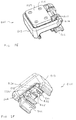
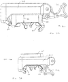
Figures 1A - 1H are illustrations of various views of the Accessory Mounting Apparatus which provides mechanical interconnection and electrical interconnection of a Power-Consuming Accessory to the Powered Rail of a weapon; -
Figures 2A and 2B are illustrations of the system architecture of a military style weapon equipped with a Weapon Accessory Power Distribution System; -
Figures 3A and 3B are illustrations of a typical butt stock battery pack of the Weapon Accessory Power Distribution System; -
Figures 4A - 4C are illustrations of the Power Distribution System which interconnects the Battery Pack to the Powered Rail in the Weapon Accessory Power Distribution System; -
Figures 5A - 5C are illustrations of the Handguard assembly, including the Powered Rail, of the Weapon Accessory Power Distribution System; -
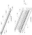
Figures 6A and6B are plan and perspective views, respectively, of two implementations of the Powered Rail, whileFigure 6C is an exploded perspective view of the Powered Rail; and -
Figures 7A - 7B illustrate the details of the Powered Rail electrical interconnection. -
Figures 2A and 2B are illustrations of the system architecture of amilitary style weapon 2 equipped with a Weapon Accessory Power Distribution System. The primary components of the basic Weapon Accessory Power Distribution System are: -
Butt Stock 21 with Battery Pack 33 (shown inFigure 3A ); -
Power Distribution System 22; - Handguard 23 (optional);
- Powered Rail 24; and
- Powered Accessory Mounting 800 (shown in
Figures 1A - 1H ). - The existing military-
style weapon 2 includes in well-known fashion anupper receiver 101,lower receiver 102,barrel 103,muzzle 104,grip 105, andfront sight 106. While a military-style weapon is described herein, the teachings of this application are equally applicable to other firearms, such as handguns, fixed mount machine guns, as well as non-Weapon based systems. The Weapon Accessory Power Distribution System is added to this standard military-style weapon 2 as described herein. - The Handguard 23 performs the barrel shielding function as in the Picatinny Rail as noted below, but has been modified, as shown in
Figures 2A and 2B to accommodate the PoweredRail 24 and electrical interconnection of the PoweredAccessory Mounting 800 to the Powered Rail 24, as described below. In particular, a combination of PoweredRails 24 and Handguardsections 23 are attached together to form a structure which encircles thebarrel 103. The Powered Rails 24 in effect forms facets around the periphery of the resultant Handguard structure. Thus, herein the term "Handguard" is used to represent the sections of handguard structure as well as the well-known combination of Handguard sections and Powered Rails which encircle thebarrel 103 as shown inFigures 2A and 2B . As alternative structures, the Powered Rail 24 can be attached to a Handguard 23 that encircles the barrel. Furthermore, there is no requirement to use the Handguard 23 as an integral component of the Weapon Accessory Power Distribution System, so the Handguard 23 can be optional, with the Powered Rail(s) 24 being attached to the weapon in some other manner, such as anupper receiver rail 101 inFigure 2A . For the purpose of illustrating the Weapon Accessory Power Distribution System, the first of the above-listed configurations is used herein. - As noted above, the Handguard 23 was developed to shroud the
barrel 103 of arapid fire weapon 2 to enable the person firing theweapon 2 to grip the forward portion of theweapon 2 while mitigating the possibility of burning the hand of the person firing theweapon 2, yet also providing adequate cooling for thebarrel 103 of the weapon. Handguards find application in rifles, carbines, and fixed mount Weapons, such as machine guns. However, the Weapon Accessory Control System can also be used in modified form for handguns, as an accessory mounting platform, and as an accessory power source. -
Figures 5A - 5C are perspective exploded view, side view, and end view illustrations, respectively, of the Handguard 23 assembly, including the Powered Rail 24, of the Weapon Accessory Control System. The Powered Rail 24, as shown as an example, includes a series of ridges with a T-shaped cross-section interspersed with flat "spacing slots". This version of the Handguard 23 includes one or more power distribution Printed Circuit Boards 60-1 to 60-4, withFigure 5C showing an end view of the slots formed in the various facets F1-F4 of the Handguard 23. Apertures A are provided along the length dimension L of the Handguard 23 to enable thebarrel 103 of theweapon 2 to be cooled by air circulation from the ambient environment. Other Powered Rail configurations are possible, and this architecture is provided as an illustration of the concepts of the Weapon Accessory Power Distribution System. - One or more of the Powered Rail subassemblies (typically Printed Circuit Boards) 60-1 to 60-4 can be inserted into the respective slots formed in the Powered Rail 24 (on the corresponding facets F1-F4 of the Handguard 23) thereby to enable power-consuming accessories to be attached to the
Handguard 23 of theweapon 2 via the PoweredRail 24 on any facet F1-F4 of the Handguard 23 and to be powered by the corresponding Printed Circuit Board 60-1 to 60-4 installed in the Powered Rail 24 on that facet. - The Battery Pack can be implemented in a number of assemblies and mounted on various portions of the weapon (such as on the Powered Rail, or in a pistol grip, or in a remote power source, and the like). For the purpose of this description,
Figures 3A and 3B are illustrations of atypical Butt Stock 21 withBattery Pack 33 of the Weapon Accessory Control System. For example, a butt stock/recoil tube battery pack assembly includes anadjustable butt stock 21, acam latch 32, and aremovable battery pack 33. Thebutt stock 21 adds a compartment to the underside of the existing lower receiver extension (also termed "buffer tube" herein)assembly 34 which allows thebattery pack 33 to be installed and withdrawn for removal through the rear of the rifle. Thebattery pack 33 mounts on thebuffer tube assembly 34 independent of thebutt stock 21 which telescopes along the rifle. Thebutt stock 21 is adjustable and can be extended in various multiple intermediate positions to provide an adjustable length of the firearm, as is well known in the art. By moving the mass of the battery rearward on the weapon, the time required to bring the weapon to point is reduced, as well as the time needed to "stop" the muzzle when the target is acquired. - The
Power Distribution System 22 is shown inFigures 2A, 2B , and4A - 4C as a one-piece housing 201 and ruggedizedpower rail connector 202 where sealing integrity is maintained during exposure to adverse environmental conditions. Thepower rail connector 202 consists of a metallic shell body,contact pin receptacle 203, with a press fitmulti-finger spring contact 204 assembled into thecontact pin receptacle 203. Themulti-finger spring contact 204 provides compliance to variations in the mating pin to ensure continuous current carrying capacity of the connection. Thecontact pin receptacle 203 includes a solder tail portion for soldering cable wires. Thebottom panel insulator 205 mounts thepin receptacles 203 with the bottom part fitted over the connectorcontact pin receptacle 203 and is sealed with a sealing compound. Afastener 206 and retainingring 207 are used to secure the connector assembly into the rail pin contacts. - An electric wire is routed from the
Battery Pack 33 in theButt Stock 21 to thePowered Rail 24. The external wiring is housed inside a durable and impactresistant polymer shroud 108 that conforms to thelower receiver 102. The shroud is securely retained by a quick connect/disconnect pivot andtakedown pin 111 as well as the boltrelease roll pin 109 in the trigger/hammer pins 110. The shrouded power cable runs from theBattery Power Connector 107 at theButt Stock 21 to thePower Rail Connector 202. This design provides an easy access for replacing or repairing the cable assembly, eliminates snag hazards or interferences with the rifle operation, and requires no modifications to the riflelower receiver 102 housing. - The
Powered Rail 24 is used to electrically interconnect a power source (Battery Pack 33) with the various accessories mounted on thePowered Rail 24, such that thePowered Rail 24 of theHandguard 23 provides the mechanical support for the accessory, and thePowered Rail 24 also provides the electrical interconnection. In this example, thePowered Rail 24 is attached to and coextensive with theHandguard 23 sections, such that the mounting of a Power-Consuming Accessory on thePowered Rail 24 results in simultaneous mechanical and electrical interconnection. -
Figure 6A andFigure 6B are views of two versions of thePowered Rail 24, andFigure 6C is an exploded view of thePowered Rail 24;Figures 7A and 7B illustrate the details of thePowered Rail 24 electrical interconnection; and Figures 8A - 8C are illustrations of the typical mechanical interconnection and electrical interconnection of a Power-Consuming Accessory to theHandguard 23 andPowered Rail 24. - As noted above, the
Powered Rail 24 comprises one or more Printed Circuit Board Assemblies (60-1 to 60-4) which are mounted in the apertures formed in a successive plurality of locking slots on thePowered Rail 24 to carry power to power-consuming accessories which are mounted on thePowered Rail 24 at various locations. The Printed Circuit Boards (60-1 to 60-4) are soldered to electricallyconductive busses electrical bus 72. Retaining clips 71 are manufactured from resilient metallic spring material, which are anchored on theupper rail connector 75; and aclamp hook feature 71 of the retaining clip is used to securely hold thelower rail connector 76 by engaging features formed on thelower rail connector 76.Figure 7B illustrates the retaining clips 71 and electricallyconductive busses 72 typically encapsulated in an insulative protective coating. The connector is removable and can be mounted easily through the retaining clips 71 which provide positive retention and a means of securing the connector halves. Mated connector pairs have tab features which captivate the clips. -
Figures 6A and6B illustrate the architecture of the Printed Circuit Board where remote power is applied via thepositive connector contact 61P and thenegative connector contact 61N. As shown inFigure 6A , the power is routed by the electrical traces on the PrintedCircuit Board 66. The positive current frompositive connector contact 61P is routed to the center of the Printed Circuit Board switch (for example, 63-5) where it is switched via operation of the switch 68 (shown inFigure 6C ) to contact 63P-5, while the negative current from thenegative connector contact 61N is routed to thenegative bus 62N or negative bus contact pads (for example, 62N-3). The example shown in these figures provided thirteen positions where a power-consuming accessory can be attached and contact the power contacts of thePowered Rail 24. In particular, on bothFigures 6A and6B , there are thirteenpositive contacts 62P-1 to 62P-13 (only several of which are numbered on the figures to avoid clutter). InFigure 6A , a continuousnegative buss 62N is provided as the other power source connection. InFigure 6B , the negative power source connections are provided by thirteen individual negativebus contact pads 62N-1 to 62N-13 (only several of which are numbered on the figures to avoid clutter). On the printedcircuit board 60A, there are points of attachment, typically comprisingnotches Powered Rail 24 via a pin clip arrangement. - The positive 62P-3, 62P-10, 62P-13 (for example), and negative 62N-3, 62M-10, 62N-13 contacts (on
Figure 6B ) can be continuously powered, especially in the case where only one set of contacts is provided, or can be switch activated by metallic snap dome switches 63-3, 63-10, 63-13 which are placed over positive common, and are in electrical contact with, the accessory positive switchedcontacts 62P-3, 62P-10, 62P-13. The metallic snap dome switch has a pair of conductive contacts which are normally in the open mode; when the cover of the metallic snap dome switch is depressed via a projection on the exterior surface of the power-consuming accessory which is mounted on thePowered Rail 24 juxtaposed to the metallic snap dome switch, these contacts mate and provide an electrical connection between positive common and a positive switchedcontact 62P. The metallic snap dome switch is a well-known component and consists of a curved metallic dome that spans two conductors (positive common and a positive switchedcontact 62P) such that when the dome is depressed, it snaps downward to electrically bridge the two conductors. -
Figure 6C illustrates an exploded view of the power distribution Printed Circuit Board assembly where anon-conductive layer 65 prevents the metal weapon Rail from electrically shorting the power distribution PrintedCircuit Board 62.Spacer layer 63 is a non-conductive element which holds the snap dome switches in place so they do not move laterally during assembly. Metallic snap dome switches 68 provide the electrical switching action to mounted rail accessories.Top cover layer 65 provides environmental protection to the PrintedCircuit Board 62 and the metallic snap dome switches 64 when the aforementioned layers are assembled. -
Figures 1A - 1H are illustrations of theAccessory Mounting Apparatus 800 which consists of a quick release clamp for mounting and securely attaching accessories to an accessory rail, such asPowered Rail 24. This apparatus allows for quick assembling and disassembling of accessories and tactical equipment to a weapon accessory rail system. TheAccessory Mounting Apparatus 800 can be applied as a "grabber" or mounting device on a MIL-STD-1913 "Picatinny Rail" or a NATO 4694 "Accessory Rail" or other configured accessory rails, where the accessory rails can be powered or not. TheAccessory Mounting Apparatus 800 can be adapted as a drop-in replacement for legacy rail mounts and "grabbers" being used with firearm accessories. For larger accessories, more than one of theAccessory Mounting Apparatus 800 can be linearly paired together to accommodate the larger size accessory. - The
Accessory Mounting Apparatus 800 uses a quick release clamp for mounting and securely attaching accessories to, for example, a dove-tail shaped PoweredRail 24. TheAccessory Mounting Apparatus 800 allows for quick assembling and disassembling of accessories and tactical equipment on a weapon accessory rail system. As shown inFigure 1D , theAccessory Mounting Apparatus 800 consists of abase plate 809, abody 801, latchingarm 803, andover-centered lever 802 to apply clamping force, where thebody 801 of theAccessory Mounting Apparatus 800 is keyed to align with, for example, dove-tail shaped PoweredRail 24 and fix its location in the direction of thebarrel 4 of theweapon 2. The latchingarm 803 also is keyed to align with dove-tail shaped PoweredRail 24 and, to secure the accessory to thePowered Rail 24, it is slid over the dovetail in thePowered Rail 24 and theover-centered lever 802 is closed to clamp theAccessory Mounting Apparatus 800 securely around thePowered Rail 24, fixing it in all directions. - As shown in the exploded view of the
Accessory Mounting Apparatus 800 illustrated inFigure 1D , thebase plate 809 provides a mounting surface to which an accessory is secured. A plurality ofscrews 810 are used to secure thebase plate 809 to thebody 801 of theAccessory Mounting Apparatus 800, and thesescrews 810 also can be used to secure the accessory to thebase plate 809. There are numerous ways to secure the accessory to thebase plate 809, including masking thebase plate 809 an integral part of the frame or housing of the accessory, or providing additional hardware to attach the accessory to thebase plate 809 as is known in this field. Aseating rim 808 is formed inbody 801 to receive and align thebase plate 809, andcorners 806 are shaped to match the contours of the inside of theseating rim 808 ofbody 801. - The accessory rail, such as
Powered Rail 24, includes two outwardly-facing surfaces, one on each opposite side of thePowered Rail 24, having a predefined profile to enableAccessory Mounting Apparatus 800 to attach to and align withPowered Rail 24.Accessory Mounting Apparatus 800, therefore, includes two inwardly-facing surfaces of a size and shape to mate with the two outwardly-facing surfaces of thePowered Rail 24.Figure 1G illustrates a first G1 of the two inwardly-facing surfaces which is formed in thebody 801 of theAccessory Mounting Apparatus 800 to engage a first outwardly-facing surface of thePowered Rail 24. The second G2 inwardly-facing surface of theAccessory Mounting Apparatus 800 is formed on latchingarm 803 and is movable with respect to the first G1 inwardly-facing surface of theAccessory Mounting Apparatus 800. Latchingarm 803 is pivotally connected to thebody 801 of theAccessory Mounting Apparatus 800 via pivot pins 804, 805 and is keyed to align with, for example, dove-tail shaped PoweredRail 24 and fix its location in the direction of thebarrel 4 of theweapon 2. Theover-centered lever 802 is pivotally connected to thebody 801 viapivot pin 805 and, when closed, it clamps theAccessory Mounting Apparatus 800 securely around thePowered Rail 24, fixing it in all directions. - In particular, as shown in
Figure 1G , prior to attachment to thePowered Rail 24, the two inwardly-facing surfaces G1 and G2 ofAccessory Mounting Apparatus 800 are not in horizontal alignment and the bottom side of latchingarm 803 is positioned above the bottom of body 801 a distance indicated by the arrow OS. To attachAccessory Mounting Apparatus 800 to PoweredRail 24, a user first places inwardly-facing surface G1 against a first side of thePowered Rail 24 and rotates latchingarm 803 in the direction illustrated by arrow M inFigure 1A thereby to position inwardly-facing surface G2 of latchingarm 803 against a second side of thePowered Rail 24.Over-centered lever 802 then is moved from the open position illustrated inFigure 1G to the closed position shown inFigure 1H which results in the two inwardly-facing surfaces G1 - and G2 of
Accessory Mounting Apparatus 800 being in horizontal alignment and forced against their respective sides of thePowered Rail 24 as illustrated inFigures 1B ,1C , and1E . - The
Accessory Mounting Apparatus 800 thereby provides faster securement and detachment compared to traditional screw-based or lever-based rail mounts and "grabbers." TheAccessory Mounting Apparatus 800 requires no tooling for rail securement or detachment. - When this
Accessory Mounting Apparatus 800 is used with an electrified or PoweredRail 24, it supplies power to accessories such as a flashlight, target designator, or various powered sights. As illustrated inFigures 1D and1F , a set ofelectrical contacts 822, 824-826 and switch activation pins 821, 823 (also noted as 807 onFigure 1D ) are provided to electrically interconnect with corresponding electrical contacts and switches, respectively, on thePowered Rail 24.Accessory Mounting Apparatus 800 can be mounted anywhere along the length of thePowered Rail 24 in any direction when not used to power accessories. TheAccessory Mounting Apparatus 800 also can be used as a communication interface between rail communications and an attached accessory. TheAccessory Mounting Apparatus 800 can be scaled for various dove-tail profiles that require quick securement or replacement such as mounting on vehicles (with integrated rails) or securing items temporarily on platforms. - There has been described an Accessory Mounting Apparatus. It should be understood that the particular embodiments shown in the drawings and described within this specification are for purposes of example and should not be construed to limit the invention, which is described in the claims below.
Claims (6)
- A mounting apparatus (800) for simultaneous mechanical and electrical attachment to a powered accessory rail (24), which extends along at least a portion of a length of a barrel (103) of a weapon (2) and which includes a plurality of slots formed along a length thereof and two outwardly-facing surfaces (23R, 23L) along opposite sides thereof, and which also has formed thereon a first electrical contact (62P) and a second electrical contact (62N) electrically connected to a power source (33) for providing a first and a second electrical connection to the power source (33), wherein the powered accessory rail (24) includes a switch (63) formed thereon juxtaposed to the first and second electrical contacts (62P, 62N) for applying power from the power source (33) to the first electrical contact (62P) when the switch (63) is operated, comprising:a body (801), comprising:first and second electrical contacts (822, 824-826) formed on the bottom surface of the body (801) to electrically contact the first and second electrical contacts (62P, 62N) of the powered accessory rail (24) when the mounting apparatus (800) is attached to the powered accessory rail (24),a feature (821, 823) formed on and protruding from the bottom surface of the body (801) for engaging the switch (63) formed on the powered accessory rail (24) and operating the electrical switch (63) when the mounting apparatus (800) is attached to the powered accessory rail (24),an integral inwardly-facing surface (G1) to mate with a first of the outwardly-facing surfaces (23R) of the powered accessory rail (24), andat least one keying feature to align with a corresponding one of the slots in the accessory rail (24);characterized by:a lever (802);a latching arm (803), pivotally connected to the lever (802) via a first pivot pin (804) and having an inwardly-facing surface (G2) to mate with a second (23L) of the outwardly-facing surfaces of the powered accessory rail (24); andsaid lever (802) being pivotally connected to the body (801) via a second pivot pin (805) and operable to force the inwardly-facing surface of the body (801) and the latching arm (803) into mechanical contact with respective outwardly-facing surfaces of the accessory rail (24), and, when closed, it clamps the mounting apparatus (800) securely around the powered accessory rail (24), fixing it in all directions.
- The mounting apparatus of claim 1 wherein said integral inwardly-facing surface (G1) of said body (801) has a profile that mates with said first of said outwardly-facing surfaces of the powered accessory rail (24),
and said inwardly-facing surface (G2) of said latching arm (802) has a profile that mates with said second of the outwardly-facing surfaces of the powered accessory rail (24). - The mounting apparatus of claim 1 or claim 2 wherein the latching arm (803) is pivotally connected to the lever (802) at a site above the integral inwardly-facing surface (G1) and overlays the top surface of the body (801).
- The mounting apparatus of claim 3, further comprising:a base plate (809) attached to the top surface of the body (801) for attachment to a power consuming accessory.
- The mounting apparatus of claim 1 or claim 2 wherein rotation of the lever (802) about its pivotal connection to the body (801) forces the latching arm (803) and the integral inwardly-facing surface (G1) or profile of the body (801) in a direction toward each other.
- The mounting apparatus of claim 1 or claim 2 wherein the first and second electrical contacts (62P, 62N) of the powered accessory rail (24) are formed in a slot and wherein attachment of the mounting apparatus (800) on the powered rail simultaneously mechanically secures the mounting apparatus (800) to the powered rail (24) and electrically interconnects two electrical contacts (822, 824-826) on the mounting apparatus (800) to the first and the second electrical contacts (62P, 62N) of the powered accessory rail (24).
Priority Applications (1)
| Application Number | Priority Date | Filing Date | Title |
|---|---|---|---|
| EP17199745.5A EP3296683A1 (en) | 2011-01-18 | 2011-12-30 | Apparatus for mounting accessories on the accessory rail of a weapon |
Applications Claiming Priority (2)
| Application Number | Priority Date | Filing Date | Title |
|---|---|---|---|
| US13/008,333 US8490313B2 (en) | 2011-01-18 | 2011-01-18 | Apparatus for mounting accessories on the accessory rail of a weapon |
| PCT/US2011/068106 WO2012099696A1 (en) | 2011-01-18 | 2011-12-30 | Apparatus for mounting accessories on the accessory rail of a weapon |
Related Child Applications (2)
| Application Number | Title | Priority Date | Filing Date |
|---|---|---|---|
| EP17199745.5A Division-Into EP3296683A1 (en) | 2011-01-18 | 2011-12-30 | Apparatus for mounting accessories on the accessory rail of a weapon |
| EP17199745.5A Division EP3296683A1 (en) | 2011-01-18 | 2011-12-30 | Apparatus for mounting accessories on the accessory rail of a weapon |
Publications (3)
| Publication Number | Publication Date |
|---|---|
| EP2665983A1 EP2665983A1 (en) | 2013-11-27 |
| EP2665983A4 EP2665983A4 (en) | 2014-05-21 |
| EP2665983B1 true EP2665983B1 (en) | 2017-12-13 |
Family
ID=46489639
Family Applications (2)
| Application Number | Title | Priority Date | Filing Date |
|---|---|---|---|
| EP17199745.5A Withdrawn EP3296683A1 (en) | 2011-01-18 | 2011-12-30 | Apparatus for mounting accessories on the accessory rail of a weapon |
| EP11856522.5A Not-in-force EP2665983B1 (en) | 2011-01-18 | 2011-12-30 | Apparatus for mounting accessories on the accessory rail of a weapon |
Family Applications Before (1)
| Application Number | Title | Priority Date | Filing Date |
|---|---|---|---|
| EP17199745.5A Withdrawn EP3296683A1 (en) | 2011-01-18 | 2011-12-30 | Apparatus for mounting accessories on the accessory rail of a weapon |
Country Status (7)
| Country | Link |
|---|---|
| US (1) | US8490313B2 (en) |
| EP (2) | EP3296683A1 (en) |
| AU (1) | AU2011355640B2 (en) |
| CA (1) | CA2825129C (en) |
| ES (1) | ES2663011T3 (en) |
| SG (1) | SG192043A1 (en) |
| WO (1) | WO2012099696A1 (en) |
Families Citing this family (52)
| Publication number | Priority date | Publication date | Assignee | Title |
|---|---|---|---|---|
| US8656622B2 (en) * | 2007-10-11 | 2014-02-25 | Ashbury International Group, Inc. | Tactical firearm systems and methods of manufacturing same |
| US10215529B2 (en) * | 2009-01-16 | 2019-02-26 | Prototype Productions Incorporated Ventures Two, Llc | Accessory mount for rifle accessory rail, communication, and power transfer system—accessory attachment |
| US10337834B2 (en) | 2010-01-15 | 2019-07-02 | Colt Canada Ip Holding Partnership | Networked battle system or firearm |
| US10470010B2 (en) | 2010-01-15 | 2019-11-05 | Colt Canada Ip Holding Partnership | Networked battle system or firearm |
| US9823043B2 (en) | 2010-01-15 | 2017-11-21 | Colt Canada Ip Holding Partnership | Rail for inductively powering firearm accessories |
| US10477618B2 (en) | 2010-01-15 | 2019-11-12 | Colt Canada Ip Holding Partnership | Networked battle system or firearm |
| US10477619B2 (en) | 2010-01-15 | 2019-11-12 | Colt Canada Ip Holding Partnership | Networked battle system or firearm |
| US9921028B2 (en) | 2010-01-15 | 2018-03-20 | Colt Canada Ip Holding Partnership | Apparatus and method for powering and networking a rail of a firearm |
| AU2012218790B2 (en) | 2011-02-15 | 2016-11-03 | Colt Canada Ip Holding Partnership | Apparatus and method for inductively powering and networking a rail of a firearm |
| US20120285067A1 (en) * | 2011-04-04 | 2012-11-15 | Kitzen Jonathan R | Universal rail mounting system |
| CA2881982C (en) | 2012-08-16 | 2020-10-13 | Colt Canada Corporation | Apparatus and method for powering and networking a rail of a firearm |
| US8850735B2 (en) * | 2012-10-26 | 2014-10-07 | Ra Brands, L.L.C. | Upper receiver and hand guard with cable routing guide |
| US9046320B2 (en) * | 2012-12-05 | 2015-06-02 | Keng's Firearms Specialty, Inc. | Systems, methods, and apparatus for providing a firearm sight |
| WO2014151394A1 (en) | 2013-03-15 | 2014-09-25 | Keng's Firearms Specialty, Inc. | Systems and methods for a scope mount assembly |
| EP2781875A3 (en) | 2013-03-21 | 2014-10-29 | KMS Consulting, LLC | Precision aiming system for a weapon |
| US20140360077A1 (en) * | 2013-03-27 | 2014-12-11 | Craig M. Miller | Powered tactical rail (aka picatinny rail) system and method of using the same |
| USD728722S1 (en) | 2013-04-29 | 2015-05-05 | Ashbury International Group, Inc. | Forend for modular tactical firearms |
| USD728723S1 (en) | 2013-04-29 | 2015-05-05 | Ashbury International Group, Inc. | Forend for modular tactical firearms |
| USD747780S1 (en) * | 2013-07-25 | 2016-01-19 | S & S Precision, Llc | Rail clamp with cam fastener |
| USD756763S1 (en) * | 2013-07-26 | 2016-05-24 | S & S Precision, Llc | Rail clamp with plastic snap |
| US9395158B2 (en) | 2013-09-11 | 2016-07-19 | OptiFlow, Inc. | Mounting device for weapon |
| US9200867B1 (en) * | 2014-01-08 | 2015-12-01 | Richard E. Swan | Modular integrated powered handguard and accessory mount system for combat weapons |
| US9696111B2 (en) * | 2014-08-26 | 2017-07-04 | Fxd, Llc | Auxiliary device mounting system for firearms |
| DK3292368T3 (en) * | 2015-05-04 | 2020-03-09 | Wilcox Ind Corp | POWER SUPPLY ACCESSORIES PLATE FOR THE WEAPON |
| USD826363S1 (en) | 2015-07-28 | 2018-08-21 | Crosman Corporation | Rail mounted light source |
| US10030939B2 (en) * | 2015-07-28 | 2018-07-24 | Crosman Corporation | Adjustable rail mounting system |
| US9777985B2 (en) | 2015-11-13 | 2017-10-03 | Magpul Industries Corp. | Firearm accessory attachment system |
| ITUB20160173A1 (en) * | 2016-01-27 | 2017-07-27 | Fabbrica Darmi Pietro Beretta S P A | GUIDE FOR FIRE WEAPONS |
| US10415932B1 (en) | 2016-07-22 | 2019-09-17 | Knight Vision LLLP | Adjustable weapon-based mount for a monocular night-vision goggle |
| US10047941B2 (en) | 2016-09-29 | 2018-08-14 | Crosman Corporation | Electronic device for use with deterrent device |
| USD830491S1 (en) | 2016-09-29 | 2018-10-09 | Crosman Corporation | Electronic device for use with deterrent device |
| US10466011B2 (en) * | 2017-01-01 | 2019-11-05 | S&S Precision, Llc | Weapon and accessory link |
| EP3625513B1 (en) * | 2017-05-15 | 2022-08-10 | T-Worx Holdings, LLC | Power system for a firearm |
| USD835748S1 (en) * | 2017-11-15 | 2018-12-11 | David A. Stewart | Gun rail mount |
| US11262167B2 (en) * | 2018-02-02 | 2022-03-01 | Leapers, Inc. | Quick mount for a rail |
| KR102844664B1 (en) | 2018-06-06 | 2025-08-08 | 윌콕스 인더스트리즈 코퍼레이션 | Weapon system with operator identification |
| US11320244B2 (en) | 2018-07-02 | 2022-05-03 | Alex Verjovsky | Rifle with laser and illuminator system integrated into rail |
| US10782101B2 (en) * | 2018-07-25 | 2020-09-22 | Trijicon, Inc. | Powered mount for firearm |
| US12215956B2 (en) * | 2018-12-21 | 2025-02-04 | Bravo Company Mfg, Inc. | Firearm accessory mount with angled hardware |
| US10935348B2 (en) | 2019-02-25 | 2021-03-02 | Haoqian Liu | Locking mechanism to secure a firearm accessory mount to a picatinny rail |
| USD947979S1 (en) * | 2019-10-10 | 2022-04-05 | T-Worx Holdings, LLC | Electrical contact strip for a powered rail |
| EP3835709A1 (en) * | 2019-12-11 | 2021-06-16 | FN Herstal S.A. | Mounting rail for a firearm |
| RU2720504C1 (en) * | 2019-12-20 | 2020-04-30 | Акционерное общество "Концерн "Калашников" | Attachment assembly of additional equipment on small arms |
| USD1025273S1 (en) | 2019-12-20 | 2024-04-30 | Bravo Company Mfg, Inc. | Firearm accessory mount |
| USD973826S1 (en) | 2019-12-20 | 2022-12-27 | Bravo Company Mfg, Inc. | Firearm accessory mount |
| US11473872B2 (en) | 2020-02-13 | 2022-10-18 | Sellmark Corporation | Firearm accessory mount |
| US10969201B1 (en) | 2020-02-13 | 2021-04-06 | Sellmark Corporation | Firearm accessory mount |
| WO2021203032A1 (en) | 2020-04-02 | 2021-10-07 | T-Worx Holdings, LLC | High-throughput data communication for rail-mounted devices |
| US20220341697A1 (en) * | 2021-04-21 | 2022-10-27 | T-Worx Holdings, LLC | Electrical power source for a firearm |
| US11716807B2 (en) * | 2021-12-09 | 2023-08-01 | Fieldpiece Instruments, Inc. | Power and communication handguard |
| US20250085080A1 (en) * | 2023-09-13 | 2025-03-13 | Wilcox Industries Corp. | Power and data retrofit for weapon accessory rail |
| US20250231009A1 (en) * | 2024-01-17 | 2025-07-17 | Wilcox Industries Corp. | Weapon accessory riser and integral keypad for weapon handguard |
Citations (1)
| Publication number | Priority date | Publication date | Assignee | Title |
|---|---|---|---|---|
| FR2778237A1 (en) * | 1998-04-29 | 1999-11-05 | Patrick Arachequesne | Red dot sight mounting for rifle |
Family Cites Families (32)
| Publication number | Priority date | Publication date | Assignee | Title |
|---|---|---|---|---|
| US4934085A (en) * | 1989-12-20 | 1990-06-19 | The United States Of America As Represented By The Secretary Of The Army | Night sight mounting bracket for rocket launcher |
| EP0444300A3 (en) * | 1990-02-24 | 1992-08-12 | Otto Repa | Telescopic sight mounting |
| US5430967A (en) * | 1993-12-16 | 1995-07-11 | Insight Technology, Inc. | Aiming assistance device for a weapon |
| DE19918635C1 (en) * | 1999-04-23 | 2000-07-20 | Heckler & Koch Gmbh | Mounting for a telescopic sight at a hunting weapon has a longitudinal profile rail to take the mounting pedestal which has sprung side components to lock into place with easy release against the spring |
| US6438888B1 (en) * | 2001-02-07 | 2002-08-27 | Quarton, Inc. | Fixture for quickly clipping accessory on pistol |
| US6705038B2 (en) * | 2001-10-24 | 2004-03-16 | Insight Technology Inc. | Mounting assembly for a weapon accessory |
| US6606813B1 (en) | 2002-03-08 | 2003-08-19 | Exponent, Inc. | Weapon accessory mounting apparatus |
| WO2004040149A1 (en) * | 2002-10-30 | 2004-05-13 | Lars Eriksson | A retainer for an over-centre fastener |
| US7454858B2 (en) * | 2003-08-05 | 2008-11-25 | R/M Equipment, Inc. | Weapon grip assembly |
| SE0400519D0 (en) | 2004-03-03 | 2004-03-03 | Gs Dev Ab | Sight Mount for Fire Arms |
| US6922934B1 (en) * | 2004-05-24 | 2005-08-02 | Taiwan Ministry Of Defence Plant 402, Bureau Of Armaments Acquisition | Mounting bracket for scope of a gun |
| US7308772B1 (en) * | 2005-12-02 | 2007-12-18 | Millett Industries, Inc. | Articulated sight mount |
| US7886476B1 (en) * | 2006-07-28 | 2011-02-15 | Swan Richard E | Buffered mounting assembly with magnetic foot |
| US7685759B2 (en) * | 2006-11-01 | 2010-03-30 | Wilcox Industries Corp. | Three-point clamp for firearm mounting rail |
| US7905045B1 (en) * | 2006-11-02 | 2011-03-15 | Swan Richard E | Mounting assembly with adjustable spring tension |
| US8112933B1 (en) * | 2006-11-02 | 2012-02-14 | Swan Richard E | Mounting assembly with adjustable spring tension and pivoting lock lever |
| US8132355B1 (en) * | 2006-11-16 | 2012-03-13 | Alliant Techsystems Inc. | Offset accessory mount and mounting system |
| US7954971B1 (en) * | 2006-11-16 | 2011-06-07 | Blackhawk Industries Product Group Unlimited Llc | Offset mountable light accessory |
| US7802395B1 (en) * | 2006-12-11 | 2010-09-28 | Swan Richard E | Mounting assembly with positive stop for actuator arm |
| US7712242B2 (en) | 2006-12-27 | 2010-05-11 | Surefire, Llc | Rail clamp mount |
| US8091265B1 (en) * | 2007-01-10 | 2012-01-10 | Wilcox Industries Corp. | Floating rail system for firearm |
| US7845267B2 (en) * | 2007-09-11 | 2010-12-07 | Battenfield Technologies, Inc. | Attachment mechanisms for coupling firearms to supporting structures |
| US7908782B1 (en) * | 2008-04-12 | 2011-03-22 | Larue Mark C | Pivot mount for firearm sighting devices |
| US20100107467A1 (en) * | 2008-10-30 | 2010-05-06 | Machining Technologies, Inc. | Self adjusting throw lever and rail clamp system |
| US20100229450A1 (en) | 2009-01-12 | 2010-09-16 | Novatac, Inc. | Quick release weapon mount and accessories for use therewith |
| US8397418B2 (en) * | 2009-01-16 | 2013-03-19 | Prototype Productions Incorporated Ventures Two, Llc | System for providing electrical power to accessories mounted on the powered |
| US8141288B2 (en) * | 2009-01-16 | 2012-03-27 | Prototype Productions, Inc. | Rugged low light reflectivity electrical contact |
| US8104211B2 (en) * | 2009-02-05 | 2012-01-31 | Rubik Darian | Battery powered mounting rail |
| US7975419B2 (en) * | 2009-02-05 | 2011-07-12 | Rubik Darian | Mounting rail |
| DE102009023520B4 (en) * | 2009-05-30 | 2012-10-04 | Thomas Spohr | Holder for attachment for mounting on firearm with rail |
| US8006430B2 (en) * | 2009-09-15 | 2011-08-30 | Asia Optical Co., Inc. | Universal scope mount for firearm |
| US9823043B2 (en) * | 2010-01-15 | 2017-11-21 | Colt Canada Ip Holding Partnership | Rail for inductively powering firearm accessories |
-
2011
- 2011-01-18 US US13/008,333 patent/US8490313B2/en not_active Expired - Fee Related
- 2011-12-30 EP EP17199745.5A patent/EP3296683A1/en not_active Withdrawn
- 2011-12-30 SG SG2013055199A patent/SG192043A1/en unknown
- 2011-12-30 WO PCT/US2011/068106 patent/WO2012099696A1/en not_active Ceased
- 2011-12-30 AU AU2011355640A patent/AU2011355640B2/en not_active Ceased
- 2011-12-30 ES ES11856522.5T patent/ES2663011T3/en active Active
- 2011-12-30 CA CA2825129A patent/CA2825129C/en active Active
- 2011-12-30 EP EP11856522.5A patent/EP2665983B1/en not_active Not-in-force
Patent Citations (1)
| Publication number | Priority date | Publication date | Assignee | Title |
|---|---|---|---|---|
| FR2778237A1 (en) * | 1998-04-29 | 1999-11-05 | Patrick Arachequesne | Red dot sight mounting for rifle |
Non-Patent Citations (1)
| Title |
|---|
| DEPARTMENT OF DEFENSE - UNITED STATES OF AMERICA: "Design of inspection equipment for dimensional characteristics", vol. MIL-HDBK-204 Rev. A, 30 November 1990 (1990-11-30), Retrieved from the Internet <URL:https://www.google.com/url?q=http://everyspec.com/MIL-HDBK/MIL-HDBK-0200-0299/download.php%3Fspec%3DMIL_HDBK_204A.1972.pdf&sa=U&ved=0ahUKEwj8nMqC2afOAhVIjSwKHSamDWE4ChAWCAUwAA&client=internal-uds-cse&usg=AFQjCNHO7Md5WoetE8nKj6kdlBb01JScXA> [retrieved on 20160803] * |
Also Published As
| Publication number | Publication date |
|---|---|
| US20120180363A1 (en) | 2012-07-19 |
| EP2665983A1 (en) | 2013-11-27 |
| EP3296683A1 (en) | 2018-03-21 |
| EP2665983A4 (en) | 2014-05-21 |
| WO2012099696A1 (en) | 2012-07-26 |
| AU2011355640B2 (en) | 2016-11-17 |
| US8490313B2 (en) | 2013-07-23 |
| CA2825129C (en) | 2015-12-01 |
| ES2663011T3 (en) | 2018-04-10 |
| CA2825129A1 (en) | 2012-07-26 |
| SG192043A1 (en) | 2013-08-30 |
Similar Documents
| Publication | Publication Date | Title |
|---|---|---|
| CA2825129C (en) | Apparatus for mounting accessories on the accessory rail of a weapon | |
| AU2011355640A1 (en) | Apparatus for Mounting Accessories on the accessory rail of a weapon | |
| US9285185B2 (en) | System for providing electrical power to accessories mounted on the powered rail of a weapon | |
| US8146282B2 (en) | System for providing electrical power to accessories mounted on the powered rail of a weapon | |
| US8141288B2 (en) | Rugged low light reflectivity electrical contact | |
| US8443539B2 (en) | Rail contacts for accessories mounted on the powered rail of a weapon | |
| US8516731B2 (en) | Communication and control of accessories mounted on the powered rail of a weapon | |
| US20100180485A1 (en) | Rifle accessory rail, communication, and power transfer system - power distribution | |
| US8448368B2 (en) | Rifle accessory rail, communication, and power transfer system—rail contacts | |
| US10663261B2 (en) | Scope mount with electrical connectivity hub | |
| US11391538B2 (en) | Firearm with electrical power source | |
| US9448030B2 (en) | Grip/cover for key lock system | |
| US7975419B2 (en) | Mounting rail | |
| US20130061504A1 (en) | Communication and power distribution system and segmented rail adapter | |
| US20110010979A1 (en) | Mounting rail assembly for firearms | |
| AU2018270152A1 (en) | Power system for a firearm | |
| WO2022256084A2 (en) | Electrical connector for a firearm | |
| WO2021145891A1 (en) | Firearm with electrical power source |
Legal Events
| Date | Code | Title | Description |
|---|---|---|---|
| PUAI | Public reference made under article 153(3) epc to a published international application that has entered the european phase |
Free format text: ORIGINAL CODE: 0009012 |
|
| 17P | Request for examination filed |
Effective date: 20130729 |
|
| AK | Designated contracting states |
Kind code of ref document: A1 Designated state(s): AL AT BE BG CH CY CZ DE DK EE ES FI FR GB GR HR HU IE IS IT LI LT LU LV MC MK MT NL NO PL PT RO RS SE SI SK SM TR |
|
| DAX | Request for extension of the european patent (deleted) | ||
| A4 | Supplementary search report drawn up and despatched |
Effective date: 20140425 |
|
| RIC1 | Information provided on ipc code assigned before grant |
Ipc: F41C 27/00 20060101AFI20140417BHEP Ipc: F41G 11/00 20060101ALI20140417BHEP |
|
| 17Q | First examination report despatched |
Effective date: 20150619 |
|
| GRAP | Despatch of communication of intention to grant a patent |
Free format text: ORIGINAL CODE: EPIDOSNIGR1 |
|
| INTG | Intention to grant announced |
Effective date: 20170628 |
|
| RIN1 | Information on inventor provided before grant (corrected) |
Inventor name: TAPIA, HECTOR Inventor name: PAULSEN, GREG Inventor name: FELDMAN, BEN Inventor name: DODD, JAMES S. Inventor name: FRASCATI, JOSEPH |
|
| GRAS | Grant fee paid |
Free format text: ORIGINAL CODE: EPIDOSNIGR3 |
|
| GRAA | (expected) grant |
Free format text: ORIGINAL CODE: 0009210 |
|
| AK | Designated contracting states |
Kind code of ref document: B1 Designated state(s): AL AT BE BG CH CY CZ DE DK EE ES FI FR GB GR HR HU IE IS IT LI LT LU LV MC MK MT NL NO PL PT RO RS SE SI SK SM TR |
|
| REG | Reference to a national code |
Ref country code: GB Ref legal event code: FG4D |
|
| REG | Reference to a national code |
Ref country code: AT Ref legal event code: REF Ref document number: 954819 Country of ref document: AT Kind code of ref document: T Effective date: 20171215 Ref country code: CH Ref legal event code: EP |
|
| REG | Reference to a national code |
Ref country code: IE Ref legal event code: FG4D |
|
| REG | Reference to a national code |
Ref country code: DE Ref legal event code: R096 Ref document number: 602011044255 Country of ref document: DE |
|
| REG | Reference to a national code |
Ref country code: FR Ref legal event code: PLFP Year of fee payment: 7 |
|
| REG | Reference to a national code |
Ref country code: SE Ref legal event code: TRGR |
|
| REG | Reference to a national code |
Ref country code: ES Ref legal event code: FG2A Ref document number: 2663011 Country of ref document: ES Kind code of ref document: T3 Effective date: 20180410 |
|
| REG | Reference to a national code |
Ref country code: NL Ref legal event code: MP Effective date: 20171213 |
|
| REG | Reference to a national code |
Ref country code: LT Ref legal event code: MG4D |
|
| PG25 | Lapsed in a contracting state [announced via postgrant information from national office to epo] |
Ref country code: LT Free format text: LAPSE BECAUSE OF FAILURE TO SUBMIT A TRANSLATION OF THE DESCRIPTION OR TO PAY THE FEE WITHIN THE PRESCRIBED TIME-LIMIT Effective date: 20171213 Ref country code: NO Free format text: LAPSE BECAUSE OF FAILURE TO SUBMIT A TRANSLATION OF THE DESCRIPTION OR TO PAY THE FEE WITHIN THE PRESCRIBED TIME-LIMIT Effective date: 20180313 Ref country code: FI Free format text: LAPSE BECAUSE OF FAILURE TO SUBMIT A TRANSLATION OF THE DESCRIPTION OR TO PAY THE FEE WITHIN THE PRESCRIBED TIME-LIMIT Effective date: 20171213 |
|
| REG | Reference to a national code |
Ref country code: AT Ref legal event code: MK05 Ref document number: 954819 Country of ref document: AT Kind code of ref document: T Effective date: 20171213 |
|
| PG25 | Lapsed in a contracting state [announced via postgrant information from national office to epo] |
Ref country code: LV Free format text: LAPSE BECAUSE OF FAILURE TO SUBMIT A TRANSLATION OF THE DESCRIPTION OR TO PAY THE FEE WITHIN THE PRESCRIBED TIME-LIMIT Effective date: 20171213 Ref country code: BG Free format text: LAPSE BECAUSE OF FAILURE TO SUBMIT A TRANSLATION OF THE DESCRIPTION OR TO PAY THE FEE WITHIN THE PRESCRIBED TIME-LIMIT Effective date: 20180313 Ref country code: GR Free format text: LAPSE BECAUSE OF FAILURE TO SUBMIT A TRANSLATION OF THE DESCRIPTION OR TO PAY THE FEE WITHIN THE PRESCRIBED TIME-LIMIT Effective date: 20180314 Ref country code: HR Free format text: LAPSE BECAUSE OF FAILURE TO SUBMIT A TRANSLATION OF THE DESCRIPTION OR TO PAY THE FEE WITHIN THE PRESCRIBED TIME-LIMIT Effective date: 20171213 Ref country code: RS Free format text: LAPSE BECAUSE OF FAILURE TO SUBMIT A TRANSLATION OF THE DESCRIPTION OR TO PAY THE FEE WITHIN THE PRESCRIBED TIME-LIMIT Effective date: 20171213 |
|
| PG25 | Lapsed in a contracting state [announced via postgrant information from national office to epo] |
Ref country code: NL Free format text: LAPSE BECAUSE OF FAILURE TO SUBMIT A TRANSLATION OF THE DESCRIPTION OR TO PAY THE FEE WITHIN THE PRESCRIBED TIME-LIMIT Effective date: 20171213 |
|
| PG25 | Lapsed in a contracting state [announced via postgrant information from national office to epo] |
Ref country code: CZ Free format text: LAPSE BECAUSE OF FAILURE TO SUBMIT A TRANSLATION OF THE DESCRIPTION OR TO PAY THE FEE WITHIN THE PRESCRIBED TIME-LIMIT Effective date: 20171213 Ref country code: SK Free format text: LAPSE BECAUSE OF FAILURE TO SUBMIT A TRANSLATION OF THE DESCRIPTION OR TO PAY THE FEE WITHIN THE PRESCRIBED TIME-LIMIT Effective date: 20171213 Ref country code: CY Free format text: LAPSE BECAUSE OF FAILURE TO SUBMIT A TRANSLATION OF THE DESCRIPTION OR TO PAY THE FEE WITHIN THE PRESCRIBED TIME-LIMIT Effective date: 20171213 Ref country code: EE Free format text: LAPSE BECAUSE OF FAILURE TO SUBMIT A TRANSLATION OF THE DESCRIPTION OR TO PAY THE FEE WITHIN THE PRESCRIBED TIME-LIMIT Effective date: 20171213 |
|
| PGFP | Annual fee paid to national office [announced via postgrant information from national office to epo] |
Ref country code: LU Payment date: 20180611 Year of fee payment: 7 Ref country code: CH Payment date: 20180629 Year of fee payment: 7 Ref country code: MC Payment date: 20180615 Year of fee payment: 7 Ref country code: IE Payment date: 20180613 Year of fee payment: 7 |
|
| PG25 | Lapsed in a contracting state [announced via postgrant information from national office to epo] |
Ref country code: RO Free format text: LAPSE BECAUSE OF FAILURE TO SUBMIT A TRANSLATION OF THE DESCRIPTION OR TO PAY THE FEE WITHIN THE PRESCRIBED TIME-LIMIT Effective date: 20171213 Ref country code: SM Free format text: LAPSE BECAUSE OF FAILURE TO SUBMIT A TRANSLATION OF THE DESCRIPTION OR TO PAY THE FEE WITHIN THE PRESCRIBED TIME-LIMIT Effective date: 20171213 Ref country code: PL Free format text: LAPSE BECAUSE OF FAILURE TO SUBMIT A TRANSLATION OF THE DESCRIPTION OR TO PAY THE FEE WITHIN THE PRESCRIBED TIME-LIMIT Effective date: 20171213 Ref country code: IS Free format text: LAPSE BECAUSE OF FAILURE TO SUBMIT A TRANSLATION OF THE DESCRIPTION OR TO PAY THE FEE WITHIN THE PRESCRIBED TIME-LIMIT Effective date: 20180413 Ref country code: AT Free format text: LAPSE BECAUSE OF FAILURE TO SUBMIT A TRANSLATION OF THE DESCRIPTION OR TO PAY THE FEE WITHIN THE PRESCRIBED TIME-LIMIT Effective date: 20171213 |
|
| PGFP | Annual fee paid to national office [announced via postgrant information from national office to epo] |
Ref country code: BE Payment date: 20180620 Year of fee payment: 13 |
|
| REG | Reference to a national code |
Ref country code: DE Ref legal event code: R097 Ref document number: 602011044255 Country of ref document: DE |
|
| PG25 | Lapsed in a contracting state [announced via postgrant information from national office to epo] |
Ref country code: MT Free format text: LAPSE BECAUSE OF NON-PAYMENT OF DUE FEES Effective date: 20171230 |
|
| PLBE | No opposition filed within time limit |
Free format text: ORIGINAL CODE: 0009261 |
|
| STAA | Information on the status of an ep patent application or granted ep patent |
Free format text: STATUS: NO OPPOSITION FILED WITHIN TIME LIMIT |
|
| 26N | No opposition filed |
Effective date: 20180914 |
|
| PG25 | Lapsed in a contracting state [announced via postgrant information from national office to epo] |
Ref country code: DK Free format text: LAPSE BECAUSE OF FAILURE TO SUBMIT A TRANSLATION OF THE DESCRIPTION OR TO PAY THE FEE WITHIN THE PRESCRIBED TIME-LIMIT Effective date: 20171213 |
|
| PG25 | Lapsed in a contracting state [announced via postgrant information from national office to epo] |
Ref country code: SI Free format text: LAPSE BECAUSE OF FAILURE TO SUBMIT A TRANSLATION OF THE DESCRIPTION OR TO PAY THE FEE WITHIN THE PRESCRIBED TIME-LIMIT Effective date: 20171213 |
|
| PG25 | Lapsed in a contracting state [announced via postgrant information from national office to epo] |
Ref country code: HU Free format text: LAPSE BECAUSE OF FAILURE TO SUBMIT A TRANSLATION OF THE DESCRIPTION OR TO PAY THE FEE WITHIN THE PRESCRIBED TIME-LIMIT; INVALID AB INITIO Effective date: 20111230 |
|
| REG | Reference to a national code |
Ref country code: CH Ref legal event code: PL |
|
| PG25 | Lapsed in a contracting state [announced via postgrant information from national office to epo] |
Ref country code: LU Free format text: LAPSE BECAUSE OF NON-PAYMENT OF DUE FEES Effective date: 20181230 Ref country code: MC Free format text: LAPSE BECAUSE OF NON-PAYMENT OF DUE FEES Effective date: 20190102 |
|
| REG | Reference to a national code |
Ref country code: IE Ref legal event code: MM4A |
|
| REG | Reference to a national code |
Ref country code: BE Ref legal event code: MM Effective date: 20181231 |
|
| PG25 | Lapsed in a contracting state [announced via postgrant information from national office to epo] |
Ref country code: IE Free format text: LAPSE BECAUSE OF NON-PAYMENT OF DUE FEES Effective date: 20181230 |
|
| PG25 | Lapsed in a contracting state [announced via postgrant information from national office to epo] |
Ref country code: MK Free format text: LAPSE BECAUSE OF FAILURE TO SUBMIT A TRANSLATION OF THE DESCRIPTION OR TO PAY THE FEE WITHIN THE PRESCRIBED TIME-LIMIT Effective date: 20171213 Ref country code: BE Free format text: LAPSE BECAUSE OF NON-PAYMENT OF DUE FEES Effective date: 20181231 |
|
| PG25 | Lapsed in a contracting state [announced via postgrant information from national office to epo] |
Ref country code: CH Free format text: LAPSE BECAUSE OF NON-PAYMENT OF DUE FEES Effective date: 20181231 Ref country code: LI Free format text: LAPSE BECAUSE OF NON-PAYMENT OF DUE FEES Effective date: 20181231 |
|
| PG25 | Lapsed in a contracting state [announced via postgrant information from national office to epo] |
Ref country code: TR Free format text: LAPSE BECAUSE OF FAILURE TO SUBMIT A TRANSLATION OF THE DESCRIPTION OR TO PAY THE FEE WITHIN THE PRESCRIBED TIME-LIMIT Effective date: 20171213 |
|
| PG25 | Lapsed in a contracting state [announced via postgrant information from national office to epo] |
Ref country code: PT Free format text: LAPSE BECAUSE OF FAILURE TO SUBMIT A TRANSLATION OF THE DESCRIPTION OR TO PAY THE FEE WITHIN THE PRESCRIBED TIME-LIMIT Effective date: 20171213 |
|
| REG | Reference to a national code |
Ref country code: DE Ref legal event code: R082 Ref document number: 602011044255 Country of ref document: DE Representative=s name: KUHNEN & WACKER PATENT- UND RECHTSANWALTSBUERO, DE Ref country code: DE Ref legal event code: R081 Ref document number: 602011044255 Country of ref document: DE Owner name: T-WORX HOLDINGS, LLC, STERLING, US Free format text: FORMER OWNER: PROTOTYPE PRODUCTIONS, INC., ASHBURN, VA., US |
|
| REG | Reference to a national code |
Ref country code: GB Ref legal event code: 732E Free format text: REGISTERED BETWEEN 20200618 AND 20200624 |
|
| PG25 | Lapsed in a contracting state [announced via postgrant information from national office to epo] |
Ref country code: AL Free format text: LAPSE BECAUSE OF FAILURE TO SUBMIT A TRANSLATION OF THE DESCRIPTION OR TO PAY THE FEE WITHIN THE PRESCRIBED TIME-LIMIT Effective date: 20171213 |
|
| REG | Reference to a national code |
Ref country code: ES Ref legal event code: PC2A Owner name: T-WORX HOLDINGS, LLC Effective date: 20210311 |
|
| PGFP | Annual fee paid to national office [announced via postgrant information from national office to epo] |
Ref country code: ES Payment date: 20230110 Year of fee payment: 12 |
|
| PGFP | Annual fee paid to national office [announced via postgrant information from national office to epo] |
Ref country code: GB Payment date: 20231109 Year of fee payment: 13 |
|
| PGFP | Annual fee paid to national office [announced via postgrant information from national office to epo] |
Ref country code: SE Payment date: 20231110 Year of fee payment: 13 Ref country code: IT Payment date: 20231110 Year of fee payment: 13 Ref country code: FR Payment date: 20231108 Year of fee payment: 13 Ref country code: DE Payment date: 20231107 Year of fee payment: 13 |
|
| REG | Reference to a national code |
Ref country code: ES Ref legal event code: FD2A Effective date: 20250206 |
|
| PG25 | Lapsed in a contracting state [announced via postgrant information from national office to epo] |
Ref country code: ES Free format text: LAPSE BECAUSE OF NON-PAYMENT OF DUE FEES Effective date: 20231231 |
|
| REG | Reference to a national code |
Ref country code: DE Ref legal event code: R119 Ref document number: 602011044255 Country of ref document: DE |
|
| REG | Reference to a national code |
Ref country code: SE Ref legal event code: EUG |
|
| GBPC | Gb: european patent ceased through non-payment of renewal fee |
Effective date: 20241230 |
|
| PG25 | Lapsed in a contracting state [announced via postgrant information from national office to epo] |
Ref country code: DE Free format text: LAPSE BECAUSE OF NON-PAYMENT OF DUE FEES Effective date: 20250701 |
|
| PG25 | Lapsed in a contracting state [announced via postgrant information from national office to epo] |
Ref country code: IT Free format text: LAPSE BECAUSE OF NON-PAYMENT OF DUE FEES Effective date: 20241230 |
|
| PG25 | Lapsed in a contracting state [announced via postgrant information from national office to epo] |
Ref country code: GB Free format text: LAPSE BECAUSE OF NON-PAYMENT OF DUE FEES Effective date: 20241230 |
|
| PG25 | Lapsed in a contracting state [announced via postgrant information from national office to epo] |
Ref country code: FR Free format text: LAPSE BECAUSE OF NON-PAYMENT OF DUE FEES Effective date: 20241231 |