EP2665939B1 - Centrifugal electric pump for suction of aeriform fluids with liquids anti-infiltration device - Google Patents
Centrifugal electric pump for suction of aeriform fluids with liquids anti-infiltration device Download PDFInfo
- Publication number
- EP2665939B1 EP2665939B1 EP12704926.0A EP12704926A EP2665939B1 EP 2665939 B1 EP2665939 B1 EP 2665939B1 EP 12704926 A EP12704926 A EP 12704926A EP 2665939 B1 EP2665939 B1 EP 2665939B1
- Authority
- EP
- European Patent Office
- Prior art keywords
- gasket
- shaft
- motor
- suction
- electric pump
- Prior art date
- Legal status (The legal status is an assumption and is not a legal conclusion. Google has not performed a legal analysis and makes no representation as to the accuracy of the status listed.)
- Active
Links
Images


Classifications
-
- F—MECHANICAL ENGINEERING; LIGHTING; HEATING; WEAPONS; BLASTING
- F04—POSITIVE - DISPLACEMENT MACHINES FOR LIQUIDS; PUMPS FOR LIQUIDS OR ELASTIC FLUIDS
- F04D—NON-POSITIVE-DISPLACEMENT PUMPS
- F04D13/00—Pumping installations or systems
- F04D13/02—Units comprising pumps and their driving means
- F04D13/06—Units comprising pumps and their driving means the pump being electrically driven
-
- F—MECHANICAL ENGINEERING; LIGHTING; HEATING; WEAPONS; BLASTING
- F04—POSITIVE - DISPLACEMENT MACHINES FOR LIQUIDS; PUMPS FOR LIQUIDS OR ELASTIC FLUIDS
- F04D—NON-POSITIVE-DISPLACEMENT PUMPS
- F04D25/00—Pumping installations or systems
- F04D25/02—Units comprising pumps and their driving means
- F04D25/06—Units comprising pumps and their driving means the pump being electrically driven
-
- F—MECHANICAL ENGINEERING; LIGHTING; HEATING; WEAPONS; BLASTING
- F04—POSITIVE - DISPLACEMENT MACHINES FOR LIQUIDS; PUMPS FOR LIQUIDS OR ELASTIC FLUIDS
- F04D—NON-POSITIVE-DISPLACEMENT PUMPS
- F04D29/00—Details, component parts, or accessories
- F04D29/08—Sealings
- F04D29/10—Shaft sealings
- F04D29/102—Shaft sealings especially adapted for elastic fluid pumps
-
- F—MECHANICAL ENGINEERING; LIGHTING; HEATING; WEAPONS; BLASTING
- F04—POSITIVE - DISPLACEMENT MACHINES FOR LIQUIDS; PUMPS FOR LIQUIDS OR ELASTIC FLUIDS
- F04D—NON-POSITIVE-DISPLACEMENT PUMPS
- F04D29/00—Details, component parts, or accessories
- F04D29/70—Suction grids; Strainers; Dust separation; Cleaning
- F04D29/701—Suction grids; Strainers; Dust separation; Cleaning especially adapted for elastic fluid pumps
Definitions
- the present invention relates to the field of fluid machines for aeriform fluid.
- the present invention relates to a liquids anti-infiltration device for single or multistage centrifugal pumps and suction fans operated by an electric motor, particularly suitable for use as vacuum pumps in vacuum cleaners and floor washers, for cleaning surfaces through suction of air containing dust, foams or liquids, used in domestic and in industrial and professional environments.
- Centrifugal electric pumps for suction of aeriform fluids of conventional type essentially comprise an electric motor with high number of revolutions and a cylindrical suction box provided with an intake for suction of the fluid and with at least one exhaust port for discharge of said fluid. Movement of the fluid in the inner chamber of said box is caused by at least one impeller, or fan, contained therein, fitted onto the shaft of said electric motor.
- a ball bearing inserted in an annular cavity, is interposed at the coupling between the cover of said suction box and the main shaft of the electric motor, to enable rotation of the shaft and of the components fixed thereon.
- a similar pump is normally used in vacuum cleaners or floor washers to create a vacuum in a collection tank in which the dust or the liquid contained in the flow of air drawn up is deposited.
- centrifugal electric pumps for aeriform fluids have a serious drawback: during use, owing to the operating pressures and to the pressure differential created between the suction box and the motor area, due to the geometry of the components and the dimensional tolerances in play, leakages of liquid toward the area occupied by the motor can occur in proximity of the coupling bearing of the drive shaft in the suction box.
- Liquids, or even only foam or moisture in the air drawn up, can damage the ball bearing that supports the drive shaft, causing oxidation, premature wear, decreased efficiency and increased noise thereof.
- Said sealing device is obtained by a ring shaped gasket arranged in the annular cavity around the shaft and adapted to be deformed by compression, due to the force exerted by the cover of the suction box on a metal washer associated with the bearing.
- Said gasket is fixed to said cover and the drive shaft rotates by sliding thereon.
- the surface on which the gasket acts by rubbing i.e. the outer surface of the drive shaft, must be suitably treated to obtain particular reductions in the roughness values. This is somewhat complicated and onerous to produce on curved surfaces.
- DE 91 11 745 U1 discloses a liquids anti-infiltration device, usually mounted to the motors of kitchen vent hoods.
- Said decvice comprises a gasket with a cylindrical main body associated aligned with the axis of the drive shaft of the vent hood and a truncated-cone shaped sealing lip which operates by sliding directly on the closing cover of the motor, without the interposition of accessory and compensation means of the wear of said gasket.
- the aim of the invention is to overcome these limits, by producing a centrifugal electric pump for suction of aeriform fluids provided with a liquids anti-infiltration device to protect the drive shaft support bearing.
- a further aim of the invention is to produce an anti-filtration device that is highly reliable, easy to mount, adaptable to any drive shaft and tolerance between components, with increased durability, which prevents or reduces accessory fixing means and limits the costs for manufacturing and surface treatment of the metal sealing components.
- a centrifugal electric pump for suction of aeriform fluids with liquids anti-infiltration device comprising:
- said gasket is of the V-Ring type.
- a spacer is interposed between said drive shaft and said gasket.
- the main advantage consists in the excellent liquid seal produced between the suction box of said centrifugal electric pump and its electric motor, due to the shape and to the type of gasket used, and to the relative method of positioning thereof.
- the gasket operates in an optimal manner, with sliding friction on an abutment surface perpendicular to the axis of said shaft, constituted by the flat face of a metal adapter ring.
- a further advantage consists in the fact that the surface of the flat face of said metal ring can be easily subjected to honing treatments, without excessive increases in costs, obtaining an improved seal between the gasket and said ring, reduced wear of the lip of the gasket and increased durability of the device.
- the metal ring therefore makes it possible to use suitable materials and surface treatments suitable to optimize cooperation with the sealing lip of the gasket.
- the anti-infiltration device according to the invention due to cooperation between the components, to their positioning and to the configuration of the gasket, ensure a perfect seal even in the case of partial wear of said gasket: progressive wear of the sealing lip is compensated through the external pressure generated in the suction box which is exerted on said gasket, which in any case defines its contact on the flat face of the metal abutment ring.
- a further advantage consists in the simplicity with which said gasket is maintained in position solely through the operating pressure inside the electric pump, without the addition of fixing components and particular clamping systems.
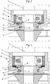
- FIG. 1 , 2 and 4 there is shown a centrifugal electric pump for suction of aeriform fluids provided with a liquids anti-infiltration device according to a preferred embodiment of the invention.
- Said electric pump 1 is essentially constituted by an electric motor 2 provided with a drive shaft 3, by a suction box 4 and by fans 8 arranged for driving a flow of air F.
- Said suction box 4 has a cylindrical shape, comprises a circular bottom provided with a suction inlet 5 arranged centrally and a lateral surface provided with at least one exhaust port 6, and is associated with said shaft 3 with a bearing 9 interposed.
- Said box 4 is closed at the top by a cover 7 adapted also to act as base for said motor 2.
- Said fans 8 are fitted onto said drive shaft 3 and are driven in movement by said motor 2.
- An annular cavity 18 arranged for housing said bearing 9 is produced between said motor shaft 3 and said cover 7.
- the anti-filtration device 10 is positioned in said annular cavity 18.
- the liquids anti-infiltration device 10 comprises a gasket 11 and a metal ring 12.
- Said gasket 11 comprises a cylindrical ring shaped main body 13, with inner diameter suitable to be fitted onto said shaft 3, and a truncated-cone shaped sealing lip 14.
- the gasket 11 is of the V-Ring type, with elastic body 13 and sealing lip 14.
- Said gasket 11 is arranged coaxially on said drive shaft 3 and rotates therewith, if necessary with a closing spacer 15 interposed, while a metal ring 12, arranged for acting as abutment surface for sliding of the sealing lip 14 of said gasket 11, is associated on the cover 7 of said suction box.
- Gaskets of this type are normally made of nitrile rubber.
- a rubber reducer 16 with the function of adapting the seat of the annular cavity 18 and retaining the bearing 9, is interposed between said metal ring 12, the cover 7 and the bearing 9.
- the operating methods of the anti-infiltration device are as follows.
- the V-Ring gasket is mounted on the motor shaft 3 and rotates therewith.
- the main body 13 is mounted with interference on the shaft 3 and maintains the lip 14 in position.
- the lip 14 produces the liquid seal against the abutment surface of the metal ring 12, arranged perpendicularly to the shaft 3.
- the elasticity of the sealing lip 14 and the high pressure inside the suction box 4 help to maintain the spacer 15 pressed against the cover 7, also compressing the gasket 11.
- the lip 14 is deformed, increasing the surface area thereof that rests on the metal ring 12 and thus preventing any liquids from leaking inside the motor 2.
Description
- The present invention relates to the field of fluid machines for aeriform fluid.
- In particular, the present invention relates to a liquids anti-infiltration device for single or multistage centrifugal pumps and suction fans operated by an electric motor, particularly suitable for use as vacuum pumps in vacuum cleaners and floor washers, for cleaning surfaces through suction of air containing dust, foams or liquids, used in domestic and in industrial and professional environments.
- Centrifugal electric pumps for suction of aeriform fluids of conventional type essentially comprise an electric motor with high number of revolutions and a cylindrical suction box provided with an intake for suction of the fluid and with at least one exhaust port for discharge of said fluid. Movement of the fluid in the inner chamber of said box is caused by at least one impeller, or fan, contained therein, fitted onto the shaft of said electric motor.
- A ball bearing, inserted in an annular cavity, is interposed at the coupling between the cover of said suction box and the main shaft of the electric motor, to enable rotation of the shaft and of the components fixed thereon.
- A similar pump is normally used in vacuum cleaners or floor washers to create a vacuum in a collection tank in which the dust or the liquid contained in the flow of air drawn up is deposited.
- These centrifugal electric pumps for aeriform fluids have a serious drawback: during use, owing to the operating pressures and to the pressure differential created between the suction box and the motor area, due to the geometry of the components and the dimensional tolerances in play, leakages of liquid toward the area occupied by the motor can occur in proximity of the coupling bearing of the drive shaft in the suction box.
- Liquids, or even only foam or moisture in the air drawn up, can damage the ball bearing that supports the drive shaft, causing oxidation, premature wear, decreased efficiency and increased noise thereof.
- Disadvantageously, various operations become necessary to carry out maintenance and to replace parts, with the related additional costs.
- A solution to this problem is disclosed in patent No.
US 6 472 786 , which describes a liquids sealing device for a centrifugal electric pump, arranged for preventing the migration of moisture along the shaft toward the motor. - Said sealing device is obtained by a ring shaped gasket arranged in the annular cavity around the shaft and adapted to be deformed by compression, due to the force exerted by the cover of the suction box on a metal washer associated with the bearing.
- Said gasket is fixed to said cover and the drive shaft rotates by sliding thereon.
- The seal to close the space that is obtained between the shaft, the bearing and the metal washer is guaranteed by the contact between the internal rim of said ring shaped gasket and said shaft.
- Disadvantageously, the point of contact and closure is very small, almost a simple rest and therefore performances are poor and deteriorate rapidly with wear of the gasket.
- Even more disadvantageously, the deformability of the ring shaped gasket must be well calculated and calibrated exactly on the basis of the space that it must occupy during its compression: the design and choice of each single gasket becomes a precise and delicate operation and does not facilitate the reproducibility of the electric pumps in series.
- As the ring shaped gasket becomes worn, the seal decreases and no type of compensation takes place, thus making it necessary to take action to replace the part, with the related additional costs and time losses.
- The surface on which the gasket acts by rubbing, i.e. the outer surface of the drive shaft, must be suitably treated to obtain particular reductions in the roughness values. This is somewhat complicated and onerous to produce on curved surfaces.
-
DE 91 11 745 U1 discloses a liquids anti-infiltration device, usually mounted to the motors of kitchen vent hoods. Said decvice comprises a gasket with a cylindrical main body associated aligned with the axis of the drive shaft of the vent hood and a truncated-cone shaped sealing lip which operates by sliding directly on the closing cover of the motor, without the interposition of accessory and compensation means of the wear of said gasket. - The aim of the invention is to overcome these limits, by producing a centrifugal electric pump for suction of aeriform fluids provided with a liquids anti-infiltration device to protect the drive shaft support bearing.
- A further aim of the invention is to produce an anti-filtration device that is highly reliable, easy to mount, adaptable to any drive shaft and tolerance between components, with increased durability, which prevents or reduces accessory fixing means and limits the costs for manufacturing and surface treatment of the metal sealing components.
- These aims are achieved with a centrifugal electric pump for suction of aeriform fluids with liquids anti-infiltration device, comprising:
- an electric motor equipped with a shaft;
- a cylindrical suction box associated with said motor, provided with an intake for aeriform fluid positioned centrally with respect to a base of said box, at least one exhaust port arranged on the lateral surface thereof and with a closing cover also arranged for acting as base for said motor;
- at least one fan, fitted onto said shaft and driven in movement by said motor, arranged for sucking a flow of air from said intake, spin it and discharge it outside said suction box through said at least one exhaust port;
- a bearing interposed between said shaft and said base of said suction box;
- a liquids anti-infiltration device, arranged between said electric motor and said suction box, provided with a gasket,
wherein said gasket rotates with said drive shaft and comprises a cylindrical main body associated with said shaft, and a truncated-cone shaped sealing lip wherein said main body and said sealing lip are made of elastic material, characterized in that said sealing lip cooperates with a flat face of a metal ring, provided between the bearing and the cover of said suction box to produce watertight closure of said box. - In particular, said gasket is of the V-Ring type. According to one embodiment of the invention, a spacer is interposed between said drive shaft and said gasket.
- The advantages of the invention are as follows.
- The main advantage consists in the excellent liquid seal produced between the suction box of said centrifugal electric pump and its electric motor, due to the shape and to the type of gasket used, and to the relative method of positioning thereof.
- In fact, the gasket operates in an optimal manner, with sliding friction on an abutment surface perpendicular to the axis of said shaft, constituted by the flat face of a metal adapter ring.
- A further advantage consists in the fact that the surface of the flat face of said metal ring can be easily subjected to honing treatments, without excessive increases in costs, obtaining an improved seal between the gasket and said ring, reduced wear of the lip of the gasket and increased durability of the device.
- The metal ring therefore makes it possible to use suitable materials and surface treatments suitable to optimize cooperation with the sealing lip of the gasket.
- Moreover, the choice of a given thickness of metal ring enables the distance between the gasket and the sliding sealing surface to be appropriately compensated.
- The gasket used also has the following advantages:
- it is extremely easy to mount, the operation can be carried out with or without the aid of a simple tool, enlarging the inner diameter of the cylindrical ring shaped body to be fitted onto the shaft;
- it has low friction and therefore generates very low load losses;
- it can also operate dry;
- due to the elastic nature, it does not require the contact surfaces to have particularly high roughness values;
- it does not cause any wear on the drive shaft and does not require particular tolerances and roughness values for this;
- a single gasket can be easily adapted to different diameters of drive shaft.
- The anti-infiltration device according to the invention, due to cooperation between the components, to their positioning and to the configuration of the gasket, ensure a perfect seal even in the case of partial wear of said gasket: progressive wear of the sealing lip is compensated through the external pressure generated in the suction box which is exerted on said gasket, which in any case defines its contact on the flat face of the metal abutment ring.
- Even more advantageously, the total absence of leakages of liquids toward the bearing protects this latter from possible wear and damage, preventing rusting which can lead to noisy operation.
- A further advantage consists in the simplicity with which said gasket is maintained in position solely through the operating pressure inside the electric pump, without the addition of fixing components and particular clamping systems.
- These and other advantages will be more evident hereinbelow, in the description of a preferred embodiment, provided by way of an indicative and non-limiting example, and with the aid of the figures wherein:
-
Figs. 1 and4 represent, respectively in cross section and in a sectional axonometric view, a centrifugal pump for suction of aeriform fluids provided with a liquids anti-infiltration device according to the invention; -
Fig. 2 represents, in cross section, a detail of the pump ofFig. 1 ; -
Fig. 3 represents, in cross section, un detail of the pump according to a possible embodiment of the invention. - With reference to
Figs. 1 ,2 and4 , there is shown a centrifugal electric pump for suction of aeriform fluids provided with a liquids anti-infiltration device according to a preferred embodiment of the invention. - Said
electric pump 1 is essentially constituted by anelectric motor 2 provided with adrive shaft 3, by asuction box 4 and by fans 8 arranged for driving a flow of air F. - Said
suction box 4 has a cylindrical shape, comprises a circular bottom provided with asuction inlet 5 arranged centrally and a lateral surface provided with at least oneexhaust port 6, and is associated with saidshaft 3 with abearing 9 interposed. - Said
box 4 is closed at the top by acover 7 adapted also to act as base for saidmotor 2. - Said fans 8 are fitted onto said
drive shaft 3 and are driven in movement by saidmotor 2. - An
annular cavity 18 arranged for housing said bearing 9 is produced between saidmotor shaft 3 and saidcover 7. - The
anti-filtration device 10 according to the invention is positioned in saidannular cavity 18. - With particular reference to
Fig. 2 , the liquidsanti-infiltration device 10 comprises agasket 11 and ametal ring 12. - Said
gasket 11 comprises a cylindrical ring shapedmain body 13, with inner diameter suitable to be fitted onto saidshaft 3, and a truncated-cone shapedsealing lip 14. - The
gasket 11 is of the V-Ring type, withelastic body 13 and sealinglip 14. - Said
gasket 11 is arranged coaxially on saiddrive shaft 3 and rotates therewith, if necessary with aclosing spacer 15 interposed, while ametal ring 12, arranged for acting as abutment surface for sliding of thesealing lip 14 of saidgasket 11, is associated on thecover 7 of said suction box. - Gaskets of this type are normally made of nitrile rubber.
- A
rubber reducer 16, with the function of adapting the seat of theannular cavity 18 and retaining thebearing 9, is interposed between saidmetal ring 12, thecover 7 and thebearing 9. - With reference to
Fig. 3 , saidrubber reducer 16 is replaced equivalently with awave washer 17. - The operating methods of the anti-infiltration device are as follows.
- The V-Ring gasket is mounted on the
motor shaft 3 and rotates therewith. Themain body 13 is mounted with interference on theshaft 3 and maintains thelip 14 in position. In particular, thelip 14 produces the liquid seal against the abutment surface of themetal ring 12, arranged perpendicularly to theshaft 3. - In use, the elasticity of the sealing
lip 14 and the high pressure inside thesuction box 4 help to maintain thespacer 15 pressed against thecover 7, also compressing thegasket 11. Thelip 14 is deformed, increasing the surface area thereof that rests on themetal ring 12 and thus preventing any liquids from leaking inside themotor 2.
Claims (3)
- A centrifugal electric pump (1) for suction of aeriform fluids provided with liquids anti-infiltration device, comprising:- an electric motor (2) equipped with a shaft (3);- a cylindrical suction box (4) associated with said motor (2), provided with an intake (5) for aeriform fluid positioned centrally with respect to a base (4') of said box, at least one exhaust port (6) arranged on the lateral surface (4") thereof and with a closing cover (7) also arranged for acting as base for said motor (2);- at least one fan (8), fitted onto said shaft (3) and driven in movement by said motor (2), arranged for sucking a flow of air (F) from said intake (5), spin it and discharge it outside said suction box (4) through said at least one exhaust port (6),- a bearing (9) interposed between said shaft and said base of said closing cover (7);- a liquids anti-infiltration device (10), arranged between said electric motor (2) and said suction box (4), provided with a gasket (11), wherein said gasket (11) rotates with said drive shaft (3) and comprises a cylindrical main body (13) associated with said shaft, and a truncated-cone shaped sealing lip (14) wherein said main body (13) and said sealing lip (14) are made of elastic material, characterized in that said sealing lip (14) cooperates with a flat face of a metal ring (12), provided between the bearing and the cover (7) of said suction box (4) to produce watertight closure of said box.
- A centrifugal electric pump (1) according to claim 1, characterized in that said gasket (11) is of the V-Ring type.
- A centrifugal electric pump (1) according to claim 1, characterized in that a spacer (15) is interposed between said motor shaft (3) and said gasket (11).
Priority Applications (1)
| Application Number | Priority Date | Filing Date | Title |
|---|---|---|---|
| RS20190204A RS58371B1 (en) | 2011-01-18 | 2012-01-16 | Centrifugal electric pump for suction of aeriform fluids with liquids anti-infiltration device |
Applications Claiming Priority (2)
| Application Number | Priority Date | Filing Date | Title |
|---|---|---|---|
| IT000002A ITCR20110002A1 (en) | 2011-01-18 | 2011-01-18 | CENTRIFUGAL ELECTRIC PUMP FOR ASPIRATION OF FLUIDS AERIFORMS WITH ANTI-INFILTRATION DEVICE OF LIQUIDS |
| PCT/IT2012/000015 WO2012098568A1 (en) | 2011-01-18 | 2012-01-16 | Centrifugal electric pump for suction of aeriform fluids with liquids anti-infiltration device |
Publications (2)
| Publication Number | Publication Date |
|---|---|
| EP2665939A1 EP2665939A1 (en) | 2013-11-27 |
| EP2665939B1 true EP2665939B1 (en) | 2018-12-12 |
Family
ID=43975302
Family Applications (1)
| Application Number | Title | Priority Date | Filing Date |
|---|---|---|---|
| EP12704926.0A Active EP2665939B1 (en) | 2011-01-18 | 2012-01-16 | Centrifugal electric pump for suction of aeriform fluids with liquids anti-infiltration device |
Country Status (6)
| Country | Link |
|---|---|
| US (1) | US20130302189A1 (en) |
| EP (1) | EP2665939B1 (en) |
| CN (1) | CN103562555A (en) |
| IT (1) | ITCR20110002A1 (en) |
| RS (1) | RS58371B1 (en) |
| WO (1) | WO2012098568A1 (en) |
Families Citing this family (3)
| Publication number | Priority date | Publication date | Assignee | Title |
|---|---|---|---|---|
| CN208522576U (en) * | 2017-09-13 | 2019-02-19 | 日本电产株式会社 | Motor, air supply device and dust catcher |
| JP7202596B2 (en) * | 2018-06-19 | 2023-01-12 | 株式会社アガツマ | Bearing packing and water supply pump |
| CN109281847A (en) * | 2018-10-12 | 2019-01-29 | 上海舟水电器有限公司 | A kind of novel drip-proof fan structure |
Citations (1)
| Publication number | Priority date | Publication date | Assignee | Title |
|---|---|---|---|---|
| US4380416A (en) * | 1978-09-25 | 1983-04-19 | Societe Internationale De Mecanique Industrielle S.A. | Centrifugal pumps |
Family Cites Families (7)
| Publication number | Priority date | Publication date | Assignee | Title |
|---|---|---|---|---|
| DE9111745U1 (en) * | 1991-09-20 | 1992-12-10 | Ebm Elektrobau Mulfingen Gmbh & Co, 7119 Mulfingen, De | |
| US6472786B1 (en) | 2000-11-17 | 2002-10-29 | Ametek, Inc. | Bearing protection assembly for motors |
| CN2924097Y (en) * | 2005-10-17 | 2007-07-18 | 宜兴市宙斯泵业有限公司 | Mechanical seal for sand-slurry pump |
| DE602006006983D1 (en) * | 2006-05-30 | 2009-07-09 | Skf Ab | Low-friction sealing ring for a centrifugal pump, in particular for a pump for internal combustion engine coolant |
| US8226384B2 (en) * | 2008-05-06 | 2012-07-24 | Ametek, Inc. | Labyrinth seal for a motor-fan unit |
| US8152449B2 (en) * | 2008-12-10 | 2012-04-10 | Honeywell International Inc. | Vacuum generator seal |
| US8297949B1 (en) * | 2009-02-17 | 2012-10-30 | Mancl Scott C | Bearing seal for a wet vacuum motor |
-
2011
- 2011-01-18 IT IT000002A patent/ITCR20110002A1/en unknown
-
2012
- 2012-01-16 EP EP12704926.0A patent/EP2665939B1/en active Active
- 2012-01-16 WO PCT/IT2012/000015 patent/WO2012098568A1/en active Application Filing
- 2012-01-16 CN CN201280010863.6A patent/CN103562555A/en active Pending
- 2012-01-16 RS RS20190204A patent/RS58371B1/en unknown
- 2012-01-16 US US13/979,898 patent/US20130302189A1/en not_active Abandoned
Patent Citations (1)
| Publication number | Priority date | Publication date | Assignee | Title |
|---|---|---|---|---|
| US4380416A (en) * | 1978-09-25 | 1983-04-19 | Societe Internationale De Mecanique Industrielle S.A. | Centrifugal pumps |
Also Published As
| Publication number | Publication date |
|---|---|
| ITCR20110002A1 (en) | 2012-07-19 |
| CN103562555A (en) | 2014-02-05 |
| US20130302189A1 (en) | 2013-11-14 |
| RS58371B1 (en) | 2019-03-29 |
| WO2012098568A1 (en) | 2012-07-26 |
| EP2665939A1 (en) | 2013-11-27 |
Similar Documents
| Publication | Publication Date | Title |
|---|---|---|
| US7131823B2 (en) | Electrically driven pump and domestic appliance having the pump | |
| EP2665939B1 (en) | Centrifugal electric pump for suction of aeriform fluids with liquids anti-infiltration device | |
| TWI650485B (en) | Magnetic pump | |
| US20050260088A1 (en) | Electrically driven pump and domestic appliance having the pump | |
| CN201206556Y (en) | Vacuum pressure air pump with built-in blade sealing arrangement | |
| EP3669729A1 (en) | Packing and mounting mechanism for electric motor in small and medium-sized appliances | |
| US20070059154A1 (en) | Lateral channel compressor | |
| KR101830726B1 (en) | A under water pump improved water tightness of drive shaft | |
| RU2662848C2 (en) | Centrifugal pump stage, centrifugal pump and use of pump stage | |
| CN102080840A (en) | Range hood | |
| US6695576B2 (en) | Pump for liquids, in particular, a centrifugal pump for electric household appliances | |
| US20140286797A1 (en) | Liquid-Ring Vacuum Pump and Impeller for a Liquid-Ring Vacuum Pump | |
| JP4341208B2 (en) | Immersion pump shaft seal device | |
| JP2005344569A (en) | Pump | |
| US20230059460A1 (en) | Pump | |
| CN101344099B (en) | Electric driven blower and electric suction cleaner having the same | |
| KR101885227B1 (en) | Casing of centrifugal pump | |
| CN107829930B (en) | Automobile air conditioner compressor | |
| KR20150117012A (en) | Valve pump device | |
| CN101334038A (en) | Mini water pump | |
| CN101925747B (en) | Household appliance for washing articles | |
| CN217610895U (en) | Air draft device of floor washing machine and floor washing machine | |
| RU220833U1 (en) | CENTRIFUGAL PUMP FOR PUMPING CHEMICALLY ACTIVE LIQUIDS | |
| JP6456214B2 (en) | Pump and pump assembly method | |
| CN209704859U (en) | A kind of rotor assembly of electronic water pump for automobile |
Legal Events
| Date | Code | Title | Description |
|---|---|---|---|
| PUAI | Public reference made under article 153(3) epc to a published international application that has entered the european phase |
Free format text: ORIGINAL CODE: 0009012 |
|
| 17P | Request for examination filed |
Effective date: 20130802 |
|
| AK | Designated contracting states |
Kind code of ref document: A1 Designated state(s): AL AT BE BG CH CY CZ DE DK EE ES FI FR GB GR HR HU IE IS IT LI LT LU LV MC MK MT NL NO PL PT RO RS SE SI SK SM TR |
|
| DAX | Request for extension of the european patent (deleted) | ||
| GRAP | Despatch of communication of intention to grant a patent |
Free format text: ORIGINAL CODE: EPIDOSNIGR1 |
|
| STAA | Information on the status of an ep patent application or granted ep patent |
Free format text: STATUS: GRANT OF PATENT IS INTENDED |
|
| INTG | Intention to grant announced |
Effective date: 20180720 |
|
| GRAS | Grant fee paid |
Free format text: ORIGINAL CODE: EPIDOSNIGR3 |
|
| GRAA | (expected) grant |
Free format text: ORIGINAL CODE: 0009210 |
|
| STAA | Information on the status of an ep patent application or granted ep patent |
Free format text: STATUS: THE PATENT HAS BEEN GRANTED |
|
| AK | Designated contracting states |
Kind code of ref document: B1 Designated state(s): AL AT BE BG CH CY CZ DE DK EE ES FI FR GB GR HR HU IE IS IT LI LT LU LV MC MK MT NL NO PL PT RO RS SE SI SK SM TR |
|
| REG | Reference to a national code |
Ref country code: GB Ref legal event code: FG4D |
|
| REG | Reference to a national code |
Ref country code: CH Ref legal event code: EP |
|
| REG | Reference to a national code |
Ref country code: AT Ref legal event code: REF Ref document number: 1076388 Country of ref document: AT Kind code of ref document: T Effective date: 20181215 |
|
| REG | Reference to a national code |
Ref country code: DE Ref legal event code: R096 Ref document number: 602012054598 Country of ref document: DE |
|
| REG | Reference to a national code |
Ref country code: IE Ref legal event code: FG4D |
|
| REG | Reference to a national code |
Ref country code: NL Ref legal event code: MP Effective date: 20181212 |
|
| REG | Reference to a national code |
Ref country code: LT Ref legal event code: MG4D |
|
| PG25 | Lapsed in a contracting state [announced via postgrant information from national office to epo] |
Ref country code: HR Free format text: LAPSE BECAUSE OF FAILURE TO SUBMIT A TRANSLATION OF THE DESCRIPTION OR TO PAY THE FEE WITHIN THE PRESCRIBED TIME-LIMIT Effective date: 20181212 Ref country code: NO Free format text: LAPSE BECAUSE OF FAILURE TO SUBMIT A TRANSLATION OF THE DESCRIPTION OR TO PAY THE FEE WITHIN THE PRESCRIBED TIME-LIMIT Effective date: 20190312 Ref country code: LT Free format text: LAPSE BECAUSE OF FAILURE TO SUBMIT A TRANSLATION OF THE DESCRIPTION OR TO PAY THE FEE WITHIN THE PRESCRIBED TIME-LIMIT Effective date: 20181212 Ref country code: FI Free format text: LAPSE BECAUSE OF FAILURE TO SUBMIT A TRANSLATION OF THE DESCRIPTION OR TO PAY THE FEE WITHIN THE PRESCRIBED TIME-LIMIT Effective date: 20181212 Ref country code: ES Free format text: LAPSE BECAUSE OF FAILURE TO SUBMIT A TRANSLATION OF THE DESCRIPTION OR TO PAY THE FEE WITHIN THE PRESCRIBED TIME-LIMIT Effective date: 20181212 Ref country code: BG Free format text: LAPSE BECAUSE OF FAILURE TO SUBMIT A TRANSLATION OF THE DESCRIPTION OR TO PAY THE FEE WITHIN THE PRESCRIBED TIME-LIMIT Effective date: 20190312 Ref country code: LV Free format text: LAPSE BECAUSE OF FAILURE TO SUBMIT A TRANSLATION OF THE DESCRIPTION OR TO PAY THE FEE WITHIN THE PRESCRIBED TIME-LIMIT Effective date: 20181212 |
|
| REG | Reference to a national code |
Ref country code: AT Ref legal event code: MK05 Ref document number: 1076388 Country of ref document: AT Kind code of ref document: T Effective date: 20181212 |
|
| PG25 | Lapsed in a contracting state [announced via postgrant information from national office to epo] |
Ref country code: GR Free format text: LAPSE BECAUSE OF FAILURE TO SUBMIT A TRANSLATION OF THE DESCRIPTION OR TO PAY THE FEE WITHIN THE PRESCRIBED TIME-LIMIT Effective date: 20190313 Ref country code: AL Free format text: LAPSE BECAUSE OF FAILURE TO SUBMIT A TRANSLATION OF THE DESCRIPTION OR TO PAY THE FEE WITHIN THE PRESCRIBED TIME-LIMIT Effective date: 20181212 Ref country code: SE Free format text: LAPSE BECAUSE OF FAILURE TO SUBMIT A TRANSLATION OF THE DESCRIPTION OR TO PAY THE FEE WITHIN THE PRESCRIBED TIME-LIMIT Effective date: 20181212 |
|
| PG25 | Lapsed in a contracting state [announced via postgrant information from national office to epo] |
Ref country code: NL Free format text: LAPSE BECAUSE OF FAILURE TO SUBMIT A TRANSLATION OF THE DESCRIPTION OR TO PAY THE FEE WITHIN THE PRESCRIBED TIME-LIMIT Effective date: 20181212 |
|
| PG25 | Lapsed in a contracting state [announced via postgrant information from national office to epo] |
Ref country code: PL Free format text: LAPSE BECAUSE OF FAILURE TO SUBMIT A TRANSLATION OF THE DESCRIPTION OR TO PAY THE FEE WITHIN THE PRESCRIBED TIME-LIMIT Effective date: 20181212 Ref country code: PT Free format text: LAPSE BECAUSE OF FAILURE TO SUBMIT A TRANSLATION OF THE DESCRIPTION OR TO PAY THE FEE WITHIN THE PRESCRIBED TIME-LIMIT Effective date: 20190412 |
|
| REG | Reference to a national code |
Ref country code: DE Ref legal event code: R119 Ref document number: 602012054598 Country of ref document: DE |
|
| PG25 | Lapsed in a contracting state [announced via postgrant information from national office to epo] |
Ref country code: SK Free format text: LAPSE BECAUSE OF FAILURE TO SUBMIT A TRANSLATION OF THE DESCRIPTION OR TO PAY THE FEE WITHIN THE PRESCRIBED TIME-LIMIT Effective date: 20181212 Ref country code: SM Free format text: LAPSE BECAUSE OF FAILURE TO SUBMIT A TRANSLATION OF THE DESCRIPTION OR TO PAY THE FEE WITHIN THE PRESCRIBED TIME-LIMIT Effective date: 20181212 Ref country code: EE Free format text: LAPSE BECAUSE OF FAILURE TO SUBMIT A TRANSLATION OF THE DESCRIPTION OR TO PAY THE FEE WITHIN THE PRESCRIBED TIME-LIMIT Effective date: 20181212 Ref country code: RO Free format text: LAPSE BECAUSE OF FAILURE TO SUBMIT A TRANSLATION OF THE DESCRIPTION OR TO PAY THE FEE WITHIN THE PRESCRIBED TIME-LIMIT Effective date: 20181212 Ref country code: IS Free format text: LAPSE BECAUSE OF FAILURE TO SUBMIT A TRANSLATION OF THE DESCRIPTION OR TO PAY THE FEE WITHIN THE PRESCRIBED TIME-LIMIT Effective date: 20190412 |
|
| REG | Reference to a national code |
Ref country code: CH Ref legal event code: PL |
|
| PG25 | Lapsed in a contracting state [announced via postgrant information from national office to epo] |
Ref country code: LU Free format text: LAPSE BECAUSE OF NON-PAYMENT OF DUE FEES Effective date: 20190116 |
|
| REG | Reference to a national code |
Ref country code: BE Ref legal event code: MM Effective date: 20190131 |
|
| PLBE | No opposition filed within time limit |
Free format text: ORIGINAL CODE: 0009261 |
|
| STAA | Information on the status of an ep patent application or granted ep patent |
Free format text: STATUS: NO OPPOSITION FILED WITHIN TIME LIMIT |
|
| REG | Reference to a national code |
Ref country code: IE Ref legal event code: MM4A |
|
| PG25 | Lapsed in a contracting state [announced via postgrant information from national office to epo] |
Ref country code: MC Free format text: LAPSE BECAUSE OF FAILURE TO SUBMIT A TRANSLATION OF THE DESCRIPTION OR TO PAY THE FEE WITHIN THE PRESCRIBED TIME-LIMIT Effective date: 20181212 Ref country code: AT Free format text: LAPSE BECAUSE OF FAILURE TO SUBMIT A TRANSLATION OF THE DESCRIPTION OR TO PAY THE FEE WITHIN THE PRESCRIBED TIME-LIMIT Effective date: 20181212 Ref country code: SI Free format text: LAPSE BECAUSE OF FAILURE TO SUBMIT A TRANSLATION OF THE DESCRIPTION OR TO PAY THE FEE WITHIN THE PRESCRIBED TIME-LIMIT Effective date: 20181212 Ref country code: DE Free format text: LAPSE BECAUSE OF NON-PAYMENT OF DUE FEES Effective date: 20190801 Ref country code: DK Free format text: LAPSE BECAUSE OF FAILURE TO SUBMIT A TRANSLATION OF THE DESCRIPTION OR TO PAY THE FEE WITHIN THE PRESCRIBED TIME-LIMIT Effective date: 20181212 |
|
| 26N | No opposition filed |
Effective date: 20190913 |
|
| GBPC | Gb: european patent ceased through non-payment of renewal fee |
Effective date: 20190312 |
|
| PG25 | Lapsed in a contracting state [announced via postgrant information from national office to epo] |
Ref country code: BE Free format text: LAPSE BECAUSE OF NON-PAYMENT OF DUE FEES Effective date: 20190131 |
|
| PG25 | Lapsed in a contracting state [announced via postgrant information from national office to epo] |
Ref country code: CH Free format text: LAPSE BECAUSE OF NON-PAYMENT OF DUE FEES Effective date: 20190131 Ref country code: LI Free format text: LAPSE BECAUSE OF NON-PAYMENT OF DUE FEES Effective date: 20190131 |
|
| PG25 | Lapsed in a contracting state [announced via postgrant information from national office to epo] |
Ref country code: GB Free format text: LAPSE BECAUSE OF NON-PAYMENT OF DUE FEES Effective date: 20190312 Ref country code: IE Free format text: LAPSE BECAUSE OF NON-PAYMENT OF DUE FEES Effective date: 20190116 |
|
| PG25 | Lapsed in a contracting state [announced via postgrant information from national office to epo] |
Ref country code: FR Free format text: LAPSE BECAUSE OF NON-PAYMENT OF DUE FEES Effective date: 20190212 |
|
| PG25 | Lapsed in a contracting state [announced via postgrant information from national office to epo] |
Ref country code: TR Free format text: LAPSE BECAUSE OF FAILURE TO SUBMIT A TRANSLATION OF THE DESCRIPTION OR TO PAY THE FEE WITHIN THE PRESCRIBED TIME-LIMIT Effective date: 20181212 |
|
| PG25 | Lapsed in a contracting state [announced via postgrant information from national office to epo] |
Ref country code: MT Free format text: LAPSE BECAUSE OF NON-PAYMENT OF DUE FEES Effective date: 20190116 |
|
| PG25 | Lapsed in a contracting state [announced via postgrant information from national office to epo] |
Ref country code: CY Free format text: LAPSE BECAUSE OF FAILURE TO SUBMIT A TRANSLATION OF THE DESCRIPTION OR TO PAY THE FEE WITHIN THE PRESCRIBED TIME-LIMIT Effective date: 20181212 |
|
| PG25 | Lapsed in a contracting state [announced via postgrant information from national office to epo] |
Ref country code: HU Free format text: LAPSE BECAUSE OF FAILURE TO SUBMIT A TRANSLATION OF THE DESCRIPTION OR TO PAY THE FEE WITHIN THE PRESCRIBED TIME-LIMIT; INVALID AB INITIO Effective date: 20120116 |
|
| PG25 | Lapsed in a contracting state [announced via postgrant information from national office to epo] |
Ref country code: MK Free format text: LAPSE BECAUSE OF FAILURE TO SUBMIT A TRANSLATION OF THE DESCRIPTION OR TO PAY THE FEE WITHIN THE PRESCRIBED TIME-LIMIT Effective date: 20181212 |
|
| PGFP | Annual fee paid to national office [announced via postgrant information from national office to epo] |
Ref country code: CZ Payment date: 20230103 Year of fee payment: 12 |
|
| PGFP | Annual fee paid to national office [announced via postgrant information from national office to epo] |
Ref country code: RS Payment date: 20230104 Year of fee payment: 12 Ref country code: IT Payment date: 20221214 Year of fee payment: 12 |
|
| P01 | Opt-out of the competence of the unified patent court (upc) registered |
Effective date: 20230801 |