EP2665935B1 - Pump pulsation discharge dampener system - Google Patents
Pump pulsation discharge dampener system Download PDFInfo
- Publication number
- EP2665935B1 EP2665935B1 EP12736539.3A EP12736539A EP2665935B1 EP 2665935 B1 EP2665935 B1 EP 2665935B1 EP 12736539 A EP12736539 A EP 12736539A EP 2665935 B1 EP2665935 B1 EP 2665935B1
- Authority
- EP
- European Patent Office
- Prior art keywords
- pressure drop
- outlet
- fluid
- inlet
- outlet pipe
- Prior art date
- Legal status (The legal status is an assumption and is not a legal conclusion. Google has not performed a legal analysis and makes no representation as to the accuracy of the status listed.)
- Active
Links
- 230000010349 pulsation Effects 0.000 title claims description 52
- 239000012530 fluid Substances 0.000 claims description 52
- 238000004891 communication Methods 0.000 claims description 4
- 238000005086 pumping Methods 0.000 description 8
- 239000000446 fuel Substances 0.000 description 6
- 238000006073 displacement reaction Methods 0.000 description 3
- 230000009977 dual effect Effects 0.000 description 3
- 238000000034 method Methods 0.000 description 3
- 230000008859 change Effects 0.000 description 2
- 238000010586 diagram Methods 0.000 description 2
- 238000005553 drilling Methods 0.000 description 2
- 239000007788 liquid Substances 0.000 description 2
- 238000012986 modification Methods 0.000 description 2
- 230000004048 modification Effects 0.000 description 2
- 238000007789 sealing Methods 0.000 description 2
- 239000007787 solid Substances 0.000 description 2
- 238000005299 abrasion Methods 0.000 description 1
- 125000004122 cyclic group Chemical group 0.000 description 1
- 238000013016 damping Methods 0.000 description 1
- 230000001419 dependent effect Effects 0.000 description 1
- 238000013461 design Methods 0.000 description 1
- 230000006866 deterioration Effects 0.000 description 1
- 230000001627 detrimental effect Effects 0.000 description 1
- 238000007599 discharging Methods 0.000 description 1
- 230000000694 effects Effects 0.000 description 1
- 230000008030 elimination Effects 0.000 description 1
- 238000003379 elimination reaction Methods 0.000 description 1
- 230000006872 improvement Effects 0.000 description 1
- 238000002347 injection Methods 0.000 description 1
- 239000007924 injection Substances 0.000 description 1
- 239000000463 material Substances 0.000 description 1
- 230000007246 mechanism Effects 0.000 description 1
- 238000012856 packing Methods 0.000 description 1
- 230000001105 regulatory effect Effects 0.000 description 1
- 239000002002 slurry Substances 0.000 description 1
Images


Classifications
-
- F—MECHANICAL ENGINEERING; LIGHTING; HEATING; WEAPONS; BLASTING
- F16—ENGINEERING ELEMENTS AND UNITS; GENERAL MEASURES FOR PRODUCING AND MAINTAINING EFFECTIVE FUNCTIONING OF MACHINES OR INSTALLATIONS; THERMAL INSULATION IN GENERAL
- F16L—PIPES; JOINTS OR FITTINGS FOR PIPES; SUPPORTS FOR PIPES, CABLES OR PROTECTIVE TUBING; MEANS FOR THERMAL INSULATION IN GENERAL
- F16L55/00—Devices or appurtenances for use in, or in connection with, pipes or pipe systems
- F16L55/02—Energy absorbers; Noise absorbers
- F16L55/027—Throttle passages
-
- F—MECHANICAL ENGINEERING; LIGHTING; HEATING; WEAPONS; BLASTING
- F04—POSITIVE - DISPLACEMENT MACHINES FOR LIQUIDS; PUMPS FOR LIQUIDS OR ELASTIC FLUIDS
- F04B—POSITIVE-DISPLACEMENT MACHINES FOR LIQUIDS; PUMPS
- F04B11/00—Equalisation of pulses, e.g. by use of air vessels; Counteracting cavitation
- F04B11/0091—Equalisation of pulses, e.g. by use of air vessels; Counteracting cavitation using a special shape of fluid pass, e.g. throttles, ducts
-
- F—MECHANICAL ENGINEERING; LIGHTING; HEATING; WEAPONS; BLASTING
- F04—POSITIVE - DISPLACEMENT MACHINES FOR LIQUIDS; PUMPS FOR LIQUIDS OR ELASTIC FLUIDS
- F04B—POSITIVE-DISPLACEMENT MACHINES FOR LIQUIDS; PUMPS
- F04B39/00—Component parts, details, or accessories, of pumps or pumping systems specially adapted for elastic fluids, not otherwise provided for in, or of interest apart from, groups F04B25/00 - F04B37/00
- F04B39/0027—Pulsation and noise damping means
- F04B39/0055—Pulsation and noise damping means with a special shape of fluid passage, e.g. bends, throttles, diameter changes, pipes
- F04B39/0072—Pulsation and noise damping means with a special shape of fluid passage, e.g. bends, throttles, diameter changes, pipes characterised by assembly or mounting
-
- F—MECHANICAL ENGINEERING; LIGHTING; HEATING; WEAPONS; BLASTING
- F04—POSITIVE - DISPLACEMENT MACHINES FOR LIQUIDS; PUMPS FOR LIQUIDS OR ELASTIC FLUIDS
- F04B—POSITIVE-DISPLACEMENT MACHINES FOR LIQUIDS; PUMPS
- F04B53/00—Component parts, details or accessories not provided for in, or of interest apart from, groups F04B1/00 - F04B23/00 or F04B39/00 - F04B47/00
- F04B53/001—Noise damping
-
- F—MECHANICAL ENGINEERING; LIGHTING; HEATING; WEAPONS; BLASTING
- F16—ENGINEERING ELEMENTS AND UNITS; GENERAL MEASURES FOR PRODUCING AND MAINTAINING EFFECTIVE FUNCTIONING OF MACHINES OR INSTALLATIONS; THERMAL INSULATION IN GENERAL
- F16L—PIPES; JOINTS OR FITTINGS FOR PIPES; SUPPORTS FOR PIPES, CABLES OR PROTECTIVE TUBING; MEANS FOR THERMAL INSULATION IN GENERAL
- F16L55/00—Devices or appurtenances for use in, or in connection with, pipes or pipe systems
- F16L55/02—Energy absorbers; Noise absorbers
- F16L55/027—Throttle passages
- F16L55/02709—Throttle passages in the form of perforated plates
- F16L55/02718—Throttle passages in the form of perforated plates placed transversely
-
- F—MECHANICAL ENGINEERING; LIGHTING; HEATING; WEAPONS; BLASTING
- F16—ENGINEERING ELEMENTS AND UNITS; GENERAL MEASURES FOR PRODUCING AND MAINTAINING EFFECTIVE FUNCTIONING OF MACHINES OR INSTALLATIONS; THERMAL INSULATION IN GENERAL
- F16L—PIPES; JOINTS OR FITTINGS FOR PIPES; SUPPORTS FOR PIPES, CABLES OR PROTECTIVE TUBING; MEANS FOR THERMAL INSULATION IN GENERAL
- F16L55/00—Devices or appurtenances for use in, or in connection with, pipes or pipe systems
- F16L55/02—Energy absorbers; Noise absorbers
- F16L55/027—Throttle passages
- F16L55/02754—Throttle passages using a central core throttling the passage
-
- F—MECHANICAL ENGINEERING; LIGHTING; HEATING; WEAPONS; BLASTING
- F16—ENGINEERING ELEMENTS AND UNITS; GENERAL MEASURES FOR PRODUCING AND MAINTAINING EFFECTIVE FUNCTIONING OF MACHINES OR INSTALLATIONS; THERMAL INSULATION IN GENERAL
- F16L—PIPES; JOINTS OR FITTINGS FOR PIPES; SUPPORTS FOR PIPES, CABLES OR PROTECTIVE TUBING; MEANS FOR THERMAL INSULATION IN GENERAL
- F16L55/00—Devices or appurtenances for use in, or in connection with, pipes or pipe systems
- F16L55/04—Devices damping pulsations or vibrations in fluids
-
- Y—GENERAL TAGGING OF NEW TECHNOLOGICAL DEVELOPMENTS; GENERAL TAGGING OF CROSS-SECTIONAL TECHNOLOGIES SPANNING OVER SEVERAL SECTIONS OF THE IPC; TECHNICAL SUBJECTS COVERED BY FORMER USPC CROSS-REFERENCE ART COLLECTIONS [XRACs] AND DIGESTS
- Y10—TECHNICAL SUBJECTS COVERED BY FORMER USPC
- Y10T—TECHNICAL SUBJECTS COVERED BY FORMER US CLASSIFICATION
- Y10T137/00—Fluid handling
- Y10T137/2931—Diverse fluid containing pressure systems
- Y10T137/3115—Gas pressure storage over or displacement of liquid
- Y10T137/3118—Surge suppression
-
- Y—GENERAL TAGGING OF NEW TECHNOLOGICAL DEVELOPMENTS; GENERAL TAGGING OF CROSS-SECTIONAL TECHNOLOGIES SPANNING OVER SEVERAL SECTIONS OF THE IPC; TECHNICAL SUBJECTS COVERED BY FORMER USPC CROSS-REFERENCE ART COLLECTIONS [XRACs] AND DIGESTS
- Y10—TECHNICAL SUBJECTS COVERED BY FORMER USPC
- Y10T—TECHNICAL SUBJECTS COVERED BY FORMER US CLASSIFICATION
- Y10T137/00—Fluid handling
- Y10T137/8593—Systems
- Y10T137/85978—With pump
- Y10T137/86035—Combined with fluid receiver
- Y10T137/86043—Reserve or surge receiver
-
- Y—GENERAL TAGGING OF NEW TECHNOLOGICAL DEVELOPMENTS; GENERAL TAGGING OF CROSS-SECTIONAL TECHNOLOGIES SPANNING OVER SEVERAL SECTIONS OF THE IPC; TECHNICAL SUBJECTS COVERED BY FORMER USPC CROSS-REFERENCE ART COLLECTIONS [XRACs] AND DIGESTS
- Y10—TECHNICAL SUBJECTS COVERED BY FORMER USPC
- Y10T—TECHNICAL SUBJECTS COVERED BY FORMER US CLASSIFICATION
- Y10T137/00—Fluid handling
- Y10T137/8593—Systems
- Y10T137/86348—Tank with internally extending flow guide, pipe or conduit
-
- Y—GENERAL TAGGING OF NEW TECHNOLOGICAL DEVELOPMENTS; GENERAL TAGGING OF CROSS-SECTIONAL TECHNOLOGIES SPANNING OVER SEVERAL SECTIONS OF THE IPC; TECHNICAL SUBJECTS COVERED BY FORMER USPC CROSS-REFERENCE ART COLLECTIONS [XRACs] AND DIGESTS
- Y10—TECHNICAL SUBJECTS COVERED BY FORMER USPC
- Y10T—TECHNICAL SUBJECTS COVERED BY FORMER US CLASSIFICATION
- Y10T137/00—Fluid handling
- Y10T137/8593—Systems
- Y10T137/86381—Head-establishing standpipe or expansion chamber [e.g., surge tanks]
Definitions
- the present application relates generally to the operation of reciprocating systems and, more specifically, to providing a pump discharge pulsation dampener with dual outlets in such reciprocating systems.
- Reciprocating systems such as reciprocating pump systems and similar equipment, operate in many types of cyclic hydraulic applications.
- reciprocating mud pump systems are used to circulate the mud or drilling fluid on a drilling rig.
- Pressure peaks accelerate the deterioration of the pump, the pump's fluid end expendable parts, and equipment downstream from the pump with each subsequent pulsation. Failure to control such pressure peaks and inevitably affect the operating performance and operational life of the pump, pump fluid end expendable parts and all downstream components.
- Pulsation dampeners are typically placed immediately downstream from a reciprocating pump, often with a relative size and configuration proportional to the volume of desired fluid displacement per stroke of the pump and the maximum allotted magnitude of the pressure peaks experienced by the pump system during each pulsation. Pulsation dampeners thus aid in reducing pump loads and minimizing pulsation amplitudes to the pump, the pump's fluid end expendable parts and to equipment downstream. As a result, pulsation dampeners increase the relative operating performance and life of the pump, the pump's fluid end expendable parts and any equipment downstream from the pump.
- One type of a conventional pump discharge dampener includes an output tube that is located in the pump dampener outlet. This outlet tube passes from the interior of the pump dampener to the pump dampener outlet. All fluid flow passes through this outlet tube, also known variously as the "pressure drop tube”, “pressure drop tube assembly”, “choke tube”, “choker tube”, and other names.
- the outlet tube is a single passage tube, which may be either internal or external to a cavity. In essentially equivalent structures, orifice plates are used in lieu of tubes.
- US3353496 discloses a combination pump and pulsation dampener wherein a pulsation dampener is secured directly to the pump in a manner to constitute part of the pump body.
- US2993559 discloses a fluid surge alleviator adapted for use in conjunction with elimination of pulsations is gas and liquid lines.
- EP0780569 discloses a flow rate control means, such as an orifice, generating a flow rate regulated at part of a fuel passage of a diesel engine supplying fuel to injectors of cylinders from a pump pressurizing the fuel to a high pressure through a common rail which can stock high pressure fuel or a fuel passage having a large volume corresponding to the same, pulsation of pressure is suppressed and fluctuation of fuel injection is prevented.
- a pump discharge pulsation dampener system according to claim 1.
- a pump discharge pulsation dampener system according to claim 8.
- a pump discharge pulsation dampener system according to claim 13.
- Optional and/or preferred features are defined in the dependent claims.
- Different inner diameter internal or external pressure drop tubes or orifice plate openings producing different discharge pressure pulse amplitudes are employed in a pump pulsation control reactive discharge dampener.
- Either both pressure drop tubes/orifice plates may be mounted concurrently on or in the dampener, connected to different discharge pipes used selectively by the operator depending upon the piston or plunger size being employed, or the pressure drop tubes/orifice plates may be interchangeable.
- FIGURES 1 through 12 discussed below, and the various embodiments used to describe the principles of the present disclosure in this patent document are by way of illustration only and should not be construed in any way to limit the scope of the disclosure. Those skilled in the art will understand that the principles of the present disclosure may be implemented in any suitably arranged pump discharge dampener that has an inlet and outlet and uses an outlet tube, pressure drop tube (internal or external) or orifice plate to control or partially control pulsation amplitudes.
- FIGURE 1 is a cross sectional, somewhat simplified schematic view of a reciprocating pump system employing a pump pulsation control reactive discharge dampener having two different pressure drop tubes according to an exemplary embodiment of the present disclosure.
- Pump system 100 may employ a reciprocating pump of a type well-known and commercially available.
- the pump within pump system 100 is configured to reciprocate one or more plungers or pistons 101 (only one shown in FIGURE 1 ).
- Each piston or plunger is preferably connected by a suitable rotatable crankshaft or eccentric (not shown) mounted in a suitable "power end" housing 102.
- Power end housing 102 is connected to a fluid end structure 103 configured to have a separate pumping chamber 104 for each piston or plunger 101.
- Pumping chamber 104 is exposed to its respective piston or plunger 101.
- One such chamber 104 is shown in FIGURE 1 .
- FIGURE 1 depicts a simplified cross-sectional view through a typical pumping chamber 104.
- Fluid end 103 includes housing 105.
- Pumping chamber 104 receives fluid from inlet manifold 106 by way of a conventional poppet type inlet or suction valve 107 (only one shown).
- Piston or plunger 101 projecting at one end into chamber 104 connects to a suitable crosshead mechanism, including crosshead extension member 108.
- Crosshead extension member 108 is operably connected to a crankshaft or eccentric (not shown) in a known manner.
- Piston or plunger 101 also projects through a conventional liner or through conventional packing 109, respectively.
- Each piston or plunger 101 is preferably configured to chamber 104.
- Each piston or plunger 101 is also operably connected to discharge piping manifold 110 by way of a suitable discharge valve 111, as shown.
- Discharge piping manifold 110 typically discharges into a discharge dampener (not shown in FIGURE 1 ).
- Valves 107 and 111 are of conventional design and typically spring biased to their respective closed positions. Valves 107 and 111 each also include or are associated with removable valve seat members 112 and 113, respectively. Each of valves 107 and 111 may preferably have a seal member (not shown) formed thereon to provide fluid sealing when the valves are in their respective closed and seat engaging positions.
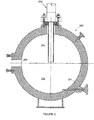
- FIGURE 2 depicts one possible discharge dampener system 200.
- Discharge dampener system 200 has a body 201 with an interior surface forming a substantially annular interior chamber 202.
- Discharge dampener system 200 is typically secured to a solid surface, for example, a drill rig floor or pump skid.
- Discharge dampener system 200 receives and discharges "fluid" (which may be entirely liquid or which may include suspended solids - i.e., a slurry) into external discharge piping 201.
- Discharge dampener system 200 includes an inlet 203 that is coupled in fluid communication with the discharge manifold 110 of pump system 100 either directly or by intervening piping (not shown), allowing all pumped fluid to enter discharge dampener system 200, becoming temporarily part of the material filling internal volume of chamber 202. All fluid then exits through internal pressure drop tube assembly 205, which directs pumped fluid into an external discharge piping system 204.
- Pressure drop tube assembly 205 is a generally T-shaped structure with the wide end outside the body 201 of chamber 202 and the length extending through an orifice in the body 201 into the interior of chamber 202.
- the pressure drop tube creates a resistance or pressure drop as a result of the fluid entering and passing through the pressure drop tube, which has a smaller inner diameter than the inner diameter of discharge piping system 204.
- the pressure drop tube 205 dampens or lowers the pulsation amplitudes, and also reduces the higher frequency energies created by the pumping actions. As the flow rate changes, however, the pressure drop tube may in some cases become ineffective or even detrimental if the inner diameter is not properly sized or adjusted, prompting the techniques of the present disclosure.
- Pumping systems may utilize different interchangeable pump pistons (or “plungers”) having different displacements, generating different fluid flow rates and pressures, etc.
- mud pumps are continually increasing in horsepower and thus can operate with a wide range of piston sizes from 5" in diameter up through 9" in diameter.
- piston or plunger size variations produce a wide range of flow rates and discharge pressures. Performance can be significantly improved if the pressure drop tubes are designed to handle narrower ranges of flow rates.
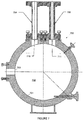
- FIGURE 3 is a somewhat simplified schematic view of a pump pulsation control reactive discharge dampener having two different pressure drop tubes according to an exemplary embodiment of the present disclosure.
- Discharge dampener 300 has an annular body 301 forming an internal cavity 302 into which fluid from pump system 100 passes via inlet 303.
- Discharge dampener 300 includes dual pressure drop tubes 304 and 305 with respective inlets 306 and 307 internal to the discharge dampener body 301 and respective outlets 308 and 309 external to the discharge dampener body 301.
- Pressure drop tubes 304 and 305 have different inside diameters producing different pressure drops.
- High flow pressure drop tube 304 has an inner diameter that is larger than low flow pressure drop tube 305.
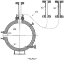
- FIGURE 4 is a somewhat simplified schematic view of a pump pulsation control reactive discharge dampener having two different pressure drop tubes according to another embodiment of the present disclosure.
- Discharge dampener 400 again includes an annular body 401 forming an interior chamber 402 receiving fluid from pumping system 100 via inlet 403.
- Discharge dampener 400 also includes dual pressure drop tubes 404 and 405 with respective inlet openings 406 and 407 internal to the body 401 coupled by tubing to respective outlet openings 407 and 408 external to the body 401, and again having different inside diameters producing different pressure drops.
- pressure drop tubes 404 and 405 are spaced apart around a periphery of the annulus and oriented at an angle such as 90° (as depicted) or 45°, or other angles as may be needed.
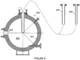
- FIGURE 5 is a somewhat simplified schematic view of a pump pulsation control reactive discharge dampener having interchangeable pressure drop tubes according to yet another exemplary embodiment of the present disclosure.
- Discharge dampener 500 includes an annular body 501 forming an interior chamber 502 fed by an inlet 503.
- the body 501 has only one discharge opening receiving only one pressure drop tube at a time, either a large inner diameter pressure drop tube 504 or a small inner diameter pressure drop tube 505.
- Either tube, when mounted, is secured at the exterior of the outlet opening with the length extending into the interior of body 501.
- FIGURES 6A through 6F are diagrams illustrating a pump pulsation control reactive discharge dampener having internal pressure drop tubes achieved by fitted sleeves with different internal diameters according to still another embodiment of the present disclosure.
- One improvement of the present disclosure is to employ a replaceable wear tip for any pressure drop tube assembly in reactive discharge dampeners.
- the inlet end of any of the pressure drop tubes 205, 304, 305, 404, 405, 504 or 505 may be fitted with an annular sleeve or end cap (described below and illustrated in FIGURES 6A through 6F ) intended to be replaced after abrasion and wear have progressed to a predetermined point.
- each sleeves must naturally be sized to fit the particular pressure drop tube on which that sleeve will be used.
- an internal pressure drop tube of the type illustrated in FIGURES 2 through 5 is achieved primarily based on the internal diameter of the inlet opening for the pressure drop tube.
- an annular sleeve of the type described above may alternatively be fitted over the end of the inlet for the pressure drop tube in a manner that modifies the internal diameter of the inlet opening.
- the inner diameter of that opening may be adjusted based on the inner diameter of the sleeve.
- Illustrated in FIGURE 6A are two pressure drop tubes of the same size having different sleeves 601 and 602 fitted over the inlet openings thereof, with different inner diameters to produce different flow characteristics.
- sleeves 601 are configured for use with a high flow rate while sleeves 603, producing a smaller inner diameter opening, are configured for use with a low flow rate.
- the same pressure drop tube may be fitted with different sleeves 601 and 602 at different times to effect the desired change.
- the sleeves are secured to the inlet ends of the internal pressure drop tubes in any suitable manner, as illustrated by sleeves 603 and 604 in FIGURE 6B , which do not fit over both the inner and outer sides of the pressure drop tube but instead only overly the inner side and the end.
- sleeves may be installed wholly internally in the pressure drop tube, as illustrated by sleeves 605, 606 and 607 in FIGURE 6C . This allows the sleeves to be employed with external pressure drop tubes of the type described in connection with FIGURES 7 through 9 .
- pressure drop tubes themselves may differ depending on the configuration of the sleeves, as illustrated by optional low flow alternative sleeves 607 fitted to a pressure drop tube having an inner diameter (and thickness) that differs from the high flow rate variant 605.
- the shape of the inner corners of a pressure drop tube inlet can change fluid flow into and through the inlet, and therefore pressure pulsation damping performance. Accordingly, the inner corner or edge of the annulus for any of the sleeves 601 through 607 may be rounded 608, sharp (square) 609 or stepped 610 as depicted in FIGURES 6D through 6F . This can be done regardless of the internal diameter. Sleeves with different inner corner or annular edge profiles may be exchanged during operation to adjust pressure pulsation amplitude dampening performance.
- FIGURE 7 illustrates an alternate embodiment to FIGURE 3 .
- discharge dampener 700 external pressure drop tubes 704 and 705 are mounted over outlet openings 710 and 711 from the body 701.
- the inner diameters of pressure drop tubes 704 and 705 are different, providing different pressure pulsation dampening characteristics.
- the inlet of the pressure drop tube may extend inward or downward into the outlet from body 701 or even into the body 701 itself, or may alternatively be flush with the flange face of the outlet from the body 701, depending on operating requirements.
- Discharge piping (not shown) may be connected to the ends of external pressure drop tubes 704 and 705 remote from the body 701.
- FIGURE 8 illustrates a similar alternative embodiment to FIGURE 4
- FIGURE 9 illustrates a similar alternative embodiment to FIGURE 5 .
- FIGURE 10 illustrates another alternate embodiment to FIGURE 3 .
- orifice plates 1004 and 1005 having different sized openings extending through the plate (and therefore optimized for different flow rates) are mounted over outlet openings 1010 and 1011 from the body 1001.
- Discharge piping (not shown) may be connected over the opposite side of orifice plates 1004 and 1005 from the body 1001.
- FIGURE 11 illustrates a similar alternative embodiment to FIGURE 4
- FIGURE 12 illustrates a similar alternative embodiment to FIGURE 5 (with discharge piping 1220 shown).
Landscapes
- Engineering & Computer Science (AREA)
- General Engineering & Computer Science (AREA)
- Mechanical Engineering (AREA)
- Reciprocating Pumps (AREA)
- Details Of Reciprocating Pumps (AREA)
- Pipe Accessories (AREA)
Description
- The present application relates generally to the operation of reciprocating systems and, more specifically, to providing a pump discharge pulsation dampener with dual outlets in such reciprocating systems.
- Reciprocating systems, such as reciprocating pump systems and similar equipment, operate in many types of cyclic hydraulic applications. For example, reciprocating mud pump systems are used to circulate the mud or drilling fluid on a drilling rig. Pressure peaks accelerate the deterioration of the pump, the pump's fluid end expendable parts, and equipment downstream from the pump with each subsequent pulsation. Failure to control such pressure peaks and inevitably affect the operating performance and operational life of the pump, pump fluid end expendable parts and all downstream components.
- Pulsation dampeners are typically placed immediately downstream from a reciprocating pump, often with a relative size and configuration proportional to the volume of desired fluid displacement per stroke of the pump and the maximum allotted magnitude of the pressure peaks experienced by the pump system during each pulsation. Pulsation dampeners thus aid in reducing pump loads and minimizing pulsation amplitudes to the pump, the pump's fluid end expendable parts and to equipment downstream. As a result, pulsation dampeners increase the relative operating performance and life of the pump, the pump's fluid end expendable parts and any equipment downstream from the pump.
- One type of a conventional pump discharge dampener includes an output tube that is located in the pump dampener outlet. This outlet tube passes from the interior of the pump dampener to the pump dampener outlet. All fluid flow passes through this outlet tube, also known variously as the "pressure drop tube", "pressure drop tube assembly", "choke tube", "choker tube", and other names. Typically, the outlet tube is a single passage tube, which may be either internal or external to a cavity. In essentially equivalent structures, orifice plates are used in lieu of tubes.
-
US3353496 discloses a combination pump and pulsation dampener wherein a pulsation dampener is secured directly to the pump in a manner to constitute part of the pump body.US2993559 discloses a fluid surge alleviator adapted for use in conjunction with elimination of pulsations is gas and liquid lines.EP0780569 discloses a flow rate control means, such as an orifice, generating a flow rate regulated at part of a fuel passage of a diesel engine supplying fuel to injectors of cylinders from a pump pressurizing the fuel to a high pressure through a common rail which can stock high pressure fuel or a fuel passage having a large volume corresponding to the same, pulsation of pressure is suppressed and fluctuation of fuel injection is prevented. - There is, therefore, a need in the art for an improved pump discharge dampener to increase performance and pump life.
- According to a first aspect of the present invention, there is provided a pump discharge pulsation dampener system according to claim 1. According to a second aspect of the present invention, there is provided a pump discharge pulsation dampener system according to claim 8. According to a third aspect of the present invention, there is provided a pump discharge pulsation dampener system according to claim 13. Optional and/or preferred features are defined in the dependent claims.
- Different inner diameter internal or external pressure drop tubes or orifice plate openings producing different discharge pressure pulse amplitudes are employed in a pump pulsation control reactive discharge dampener. Either both pressure drop tubes/orifice plates may be mounted concurrently on or in the dampener, connected to different discharge pipes used selectively by the operator depending upon the piston or plunger size being employed, or the pressure drop tubes/orifice plates may be interchangeable.
- Before undertaking the DETAILED DESCRIPTION below, it may be advantageous to set forth definitions of certain words and phrases used throughout this patent document: the terms "include" and "comprise," as well as derivatives thereof, mean inclusion without limitation; the term "or," is inclusive, meaning and/or; and the phrases "associated with" and "associated therewith," as well as derivatives thereof, may mean to include, be included within, interconnect with, contain, be contained within, connect to or with, couple to or with, be communicable with, cooperate with, interleave, juxtapose, be proximate to, be bound to or with, have, have a property of, or the like. Definitions for certain words and phrases are provided throughout this patent document, those of ordinary skill in the art should understand that in many, if not most instances, such definitions apply to prior, as well as future uses of such defined words and phrases.
- For a more complete understanding of the present disclosure and its advantages, reference is now made to the following description taken in conjunction with the accompanying drawings, in which like reference numerals represent like parts:
-
FIGURE 1 is a cross sectional, somewhat simplified schematic view of a reciprocating pump system employed with a pump pulsation control reactive discharge dampener having two different pressure drop tubes according to an exemplary embodiment of the present disclosure; -
FIGURE 2 is a somewhat simplified schematic view of one possible pump pulsation control reactive discharge dampener; -
FIGURE 3 is a somewhat simplified schematic view of a pump pulsation control reactive discharge dampener having two different internal pressure drop tubes according to an exemplary embodiment of the present disclosure; -
FIGURE 4 is a somewhat simplified schematic view of a pump pulsation control reactive discharge dampener having two different internal pressure drop tubes according to another 20 embodiment of the present disclosure; -
FIGURE 5 is a somewhat simplified schematic view of a pump pulsation control reactive discharge dampener having interchangeable internal pressure drop tubes according to yet another exemplary embodiment of the present disclosure; -
FIGURES 6A through 6F are diagrams illustrating a pump pulsation control reactive discharge dampener having internal pressure drop tubes achieved by fitted sleeves with different internal diameters according to still another embodiment of the present disclosure; -
FIGURE 7 ,FIGURE 8 andFIGURE 9 each illustrate an alternate embodiment toFIGURE 3 ,FIGURE 4 andFIGURE 5 , respectively using external pressure drop tubes rather than internal pressure drop tubes; and -
FIGURE 10 ,FIGURE 11 andFIGURE 12 each illustrate an alternate embodiment toFIGURE 3 ,FIGURE 4 andFIGURE 5 , respectively using orifice plates rather than pressure drop tubes. -
FIGURES 1 through 12 , discussed below, and the various embodiments used to describe the principles of the present disclosure in this patent document are by way of illustration only and should not be construed in any way to limit the scope of the disclosure. Those skilled in the art will understand that the principles of the present disclosure may be implemented in any suitably arranged pump discharge dampener that has an inlet and outlet and uses an outlet tube, pressure drop tube (internal or external) or orifice plate to control or partially control pulsation amplitudes. -
FIGURE 1 is a cross sectional, somewhat simplified schematic view of a reciprocating pump system employing a pump pulsation control reactive discharge dampener having two different pressure drop tubes according to an exemplary embodiment of the present disclosure.Pump system 100 may employ a reciprocating pump of a type well-known and commercially available. The pump withinpump system 100 is configured to reciprocate one or more plungers or pistons 101 (only one shown inFIGURE 1 ). Each piston or plunger is preferably connected by a suitable rotatable crankshaft or eccentric (not shown) mounted in a suitable "power end"housing 102.Power end housing 102 is connected to afluid end structure 103 configured to have aseparate pumping chamber 104 for each piston orplunger 101.Pumping chamber 104 is exposed to its respective piston orplunger 101. Onesuch chamber 104 is shown inFIGURE 1 . - More specifically,
FIGURE 1 depicts a simplified cross-sectional view through atypical pumping chamber 104.Fluid end 103 includeshousing 105.Pumping chamber 104 receives fluid frominlet manifold 106 by way of a conventional poppet type inlet or suction valve 107 (only one shown). Piston orplunger 101 projecting at one end intochamber 104 connects to a suitable crosshead mechanism, includingcrosshead extension member 108. Crossheadextension member 108 is operably connected to a crankshaft or eccentric (not shown) in a known manner. Piston orplunger 101 also projects through a conventional liner or throughconventional packing 109, respectively. Each piston orplunger 101 is preferably configured tochamber 104. Each piston orplunger 101 is also operably connected todischarge piping manifold 110 by way of asuitable discharge valve 111, as shown.Discharge piping manifold 110 typically discharges into a discharge dampener (not shown inFIGURE 1 ). Valves 107 and 111 are of conventional design and typically spring biased to their respective closed positions. Valves 107 and 111 each also include or are associated with removablevalve seat members valves 107 and 111 may preferably have a seal member (not shown) formed thereon to provide fluid sealing when the valves are in their respective closed and seat engaging positions. - Those skilled in the art will recognize that the techniques of the present disclosure may be utilized with a wide variety of single and multi-cylinder reciprocating piston or plunger power pumps as well as possibly other types of positive displacement pumps. As in example, the number of cylinders of such pumps may vary substantially between a single cylinder and essentially any number of cylinders or separate pumping chambers. Those skilled in the art will also recognize that the complete structure and operation of a suitable pump system is not depicted or described herein. Instead, for simplicity and clarity, only so much of a pump system as is unique to the present disclosure or necessary for an understanding of the present disclosure is depicted and described.
- Conventional pump systems such as
pump 100 shown inFIGURE 1 typically include a discharge dampener system.FIGURE 2 depicts one possibledischarge dampener system 200.Discharge dampener system 200 has abody 201 with an interior surface forming a substantially annularinterior chamber 202.Discharge dampener system 200 is typically secured to a solid surface, for example, a drill rig floor or pump skid.Discharge dampener system 200 receives and discharges "fluid" (which may be entirely liquid or which may include suspended solids - i.e., a slurry) into external discharge piping 201.Discharge dampener system 200 includes aninlet 203 that is coupled in fluid communication with thedischarge manifold 110 ofpump system 100 either directly or by intervening piping (not shown), allowing all pumped fluid to enterdischarge dampener system 200, becoming temporarily part of the material filling internal volume ofchamber 202. All fluid then exits through internal pressuredrop tube assembly 205, which directs pumped fluid into an externaldischarge piping system 204. Pressuredrop tube assembly 205 is a generally T-shaped structure with the wide end outside thebody 201 ofchamber 202 and the length extending through an orifice in thebody 201 into the interior ofchamber 202. - Fluid enters the internal end of pressure
drop tube assembly 205 fromcavity 202 and passes through pressuredrop tube assembly 205, discharging intodischarge piping system 204. The pressure drop tube creates a resistance or pressure drop as a result of the fluid entering and passing through the pressure drop tube, which has a smaller inner diameter than the inner diameter ofdischarge piping system 204. Thepressure drop tube 205 dampens or lowers the pulsation amplitudes, and also reduces the higher frequency energies created by the pumping actions. As the flow rate changes, however, the pressure drop tube may in some cases become ineffective or even detrimental if the inner diameter is not properly sized or adjusted, prompting the techniques of the present disclosure. - Pumping systems may utilize different interchangeable pump pistons (or "plungers") having different displacements, generating different fluid flow rates and pressures, etc. For instance, mud pumps are continually increasing in horsepower and thus can operate with a wide range of piston sizes from 5" in diameter up through 9" in diameter. These piston or plunger size variations produce a wide range of flow rates and discharge pressures. Performance can be significantly improved if the pressure drop tubes are designed to handle narrower ranges of flow rates.
-
FIGURE 3 is a somewhat simplified schematic view of a pump pulsation control reactive discharge dampener having two different pressure drop tubes according to an exemplary embodiment of the present disclosure.Discharge dampener 300 has anannular body 301 forming aninternal cavity 302 into which fluid frompump system 100 passes viainlet 303.Discharge dampener 300 includes dualpressure drop tubes respective inlets discharge dampener body 301 andrespective outlets discharge dampener body 301.Pressure drop tubes pressure drop tube 304 has an inner diameter that is larger than low flowpressure drop tube 305. This allows the operator to bring two independent discharge pipes (not shown inFIGURE 3 ) to the twoexternal outlet openings pressure drop tubes -
FIGURE 4 is a somewhat simplified schematic view of a pump pulsation control reactive discharge dampener having two different pressure drop tubes according to another embodiment of the present disclosure.Discharge dampener 400 again includes anannular body 401 forming aninterior chamber 402 receiving fluid from pumpingsystem 100 viainlet 403.Discharge dampener 400 also includes dualpressure drop tubes respective inlet openings body 401 coupled by tubing torespective outlet openings body 401, and again having different inside diameters producing different pressure drops. Rather than being situated side-by-side with parallel orientation as in the embodiment ofFIGURE 3 , however,pressure drop tubes -
FIGURE 5 is a somewhat simplified schematic view of a pump pulsation control reactive discharge dampener having interchangeable pressure drop tubes according to yet another exemplary embodiment of the present disclosure.Discharge dampener 500 includes anannular body 501 forming aninterior chamber 502 fed by aninlet 503. In this embodiment, thebody 501 has only one discharge opening receiving only one pressure drop tube at a time, either a large inner diameterpressure drop tube 504 or a small inner diameterpressure drop tube 505. Either tube, when mounted, is secured at the exterior of the outlet opening with the length extending into the interior ofbody 501. -
FIGURES 6A through 6F are diagrams illustrating a pump pulsation control reactive discharge dampener having internal pressure drop tubes achieved by fitted sleeves with different internal diameters according to still another embodiment of the present disclosure. One improvement of the present disclosure is to employ a replaceable wear tip for any pressure drop tube assembly in reactive discharge dampeners. The inlet end of any of thepressure drop tubes FIGURES 6A through 6F ) intended to be replaced after abrasion and wear have progressed to a predetermined point. Where different inner diameter pressure drop tubes are employed in the reactive dampener, each sleeves must naturally be sized to fit the particular pressure drop tube on which that sleeve will be used. - Notably, however, the pressure pulsation dampening provided by an internal pressure drop tube of the type illustrated in
FIGURES 2 through 5 is achieved primarily based on the internal diameter of the inlet opening for the pressure drop tube. Accordingly, an annular sleeve of the type described above may alternatively be fitted over the end of the inlet for the pressure drop tube in a manner that modifies the internal diameter of the inlet opening. In this manner, the inner diameter of that opening may be adjusted based on the inner diameter of the sleeve. Illustrated inFIGURE 6A are two pressure drop tubes of the same size havingdifferent sleeves sleeves 601 are configured for use with a high flow rate whilesleeves 603, producing a smaller inner diameter opening, are configured for use with a low flow rate. Alternatively, the same pressure drop tube may be fitted withdifferent sleeves sleeves FIGURE 6B , which do not fit over both the inner and outer sides of the pressure drop tube but instead only overly the inner side and the end. Similarly, sleeves may be installed wholly internally in the pressure drop tube, as illustrated bysleeves FIGURE 6C . This allows the sleeves to be employed with external pressure drop tubes of the type described in connection withFIGURES 7 through 9 . Various sleeve attachment methods and locations inside, encompassing, or outside the inlet end of a pressure drop tube are contemplated. IN addition, the pressure drop tubes themselves may differ depending on the configuration of the sleeves, as illustrated by optional low flowalternative sleeves 607 fitted to a pressure drop tube having an inner diameter (and thickness) that differs from the highflow rate variant 605. - The shape of the inner corners of a pressure drop tube inlet can change fluid flow into and through the inlet, and therefore pressure pulsation damping performance. Accordingly, the inner corner or edge of the annulus for any of the
sleeves 601 through 607 may be rounded 608, sharp (square) 609 or stepped 610 as depicted inFIGURES 6D through 6F . This can be done regardless of the internal diameter. Sleeves with different inner corner or annular edge profiles may be exchanged during operation to adjust pressure pulsation amplitude dampening performance. -
FIGURE 7 illustrates an alternate embodiment toFIGURE 3 . Indischarge dampener 700, externalpressure drop tubes outlet openings body 701. The inner diameters ofpressure drop tubes body 701 or even into thebody 701 itself, or may alternatively be flush with the flange face of the outlet from thebody 701, depending on operating requirements. Discharge piping (not shown) may be connected to the ends of externalpressure drop tubes body 701.FIGURE 8 illustrates a similar alternative embodiment toFIGURE 4 , andFIGURE 9 illustrates a similar alternative embodiment toFIGURE 5 . -
FIGURE 10 illustrates another alternate embodiment toFIGURE 3 . Instead of internal or external pressure drop tubes,orifice plates outlet openings body 1001. Discharge piping (not shown) may be connected over the opposite side oforifice plates body 1001. -
FIGURE 11 illustrates a similar alternative embodiment toFIGURE 4 , andFIGURE 12 illustrates a similar alternative embodiment toFIGURE 5 (with discharge piping 1220 shown). - Although the present disclosure has been described with exemplary embodiments, various changes and modifications may be suggested to one skilled in the art. It is intended that the present disclosure encompass such changes and modifications as fall within the scope of the appended claims.
Claims (15)
- A pump discharge pulsation dampener system comprising:
a pump discharge pulsation dampener (300, 400, 700, 800, 1000, 1100) comprising:an inlet (303, 403, 703, 803, 1003, 1103) to a body (301,401, 701, 801, 1001, 1101) of the discharge dampener;first and second outlets from the body, each in fluid communication with the inlet and each configured to allow fluid discharge from the body; wherein a selected one of the first and second outlets is open and configured to discharge fluid from an interior volume (302, 402, 502, 702, 802, 902, 1002, 1102, 1202) of the body while the other of the first and second outlets is closed, wherein the selected one of the first and second outlets is selected based on a flow rate of the fluid pumped through the inlet into the interior volume (302, 402, 502, 702, 802, 902, 1002, 1102, 1202) of the body and discharged through the selected one of the first and second outlets;a first member (304, 404, 704, 804, 1004, 1104) connected to or inserted into the first outlet and configured to contribute to discharge dampening, the first member (304, 404, 704, 804, 1004, 1104) having a fluid passage with a first inner diameter sized to produce a first pressure drop in the fluid pumped into the interior volume (302, 402, 502, 702, 802, 902, 1002, 1102, 1202) through the inlet and discharged through the first outlet, the first pressure drop contributing more to dampening of pressure pulses in the fluid when the fluid is pumped at a first flow rate than at a second flow rate different from the first flow rate; anda second member (305, 405, 705, 805, 1005, 1105) connected to or inserted into the second outlet and configured to contribute to discharge dampening, the second member having a fluid passage with a second inner diameter different than the first inner diameter sized to produce a second pressure drop different from the first pressure drop in the fluid pumped into the interior volume (302, 402, 502, 702, 802, 902, 1002, 1102, 1202) through the inlet and discharged from the second outlet, the second pressure drop contributing more to dampening of pressure pulses in the fluid when the fluid is pumped at the second flow rate than at the first flow rate. - The pump discharge pulsation dampener system (300, 400) of claim 1, wherein the first member (304, 404) is a first outlet pipe and the second member (305, 405) is a second outlet pipe, and wherein the first and second outlet pipes are internal pressure drop tubes.
- The pump discharge pulsation dampener system (700, 800) of claim 1, wherein the first member (704, 804) is a first outlet pipe and the second member (705, 805) is a second outlet pipe, wherein the first and second outlet pipes are external pressure drop tubes, and wherein an inlet for each of the first and second external pressure drop tubes is mounted flush to a flange face for the at least one outlet.
- The pump discharge pulsation dampener system (700, 800) of claim 1, wherein the first member (704, 804) is a first outlet pipe and the second member (705, 805) is a second outlet pipe, wherein the first and second outlet pipes are external pressure drop tubes, and wherein an inlet (706, 806, 707, 807) for each of the first and second external pressure drop tubes extends into the at least one outlet.
- The pump discharge pulsation dampener system (1000, 1100) of claim 1, wherein the first member (1004, 1104) is a first orifice plate and the second member (1005, 1105) is a second orifice plate.
- The pump discharge pulsation dampener system (300, 700, 1000) of claim 1, wherein the first and second outlets have approximately parallel alignment.
- The pump discharge pulsation dampener system (400, 800, 1100) of claim 1, wherein the first and second outlets have approximately perpendicular alignment.
- A pump discharge pulsation dampener system comprising:
a pump discharge pulsation dampener (500, 900, 1200) comprising:an inlet (503, 903, 1203) to a body (501, 901, 1201) of the discharge dampener (500, 900, 1200);an outlet from the body (501, 901, 1201) in fluid communication with the inlet, wherein the outlet is open and configured to discharge fluid that is pumped into an interior volume (302, 402, 502, 702, 802, 902, 1002, 1102, 1202) of the body (501, 901, 1201) through the inlet;a first member (504, 904, 1204) configured to be selectively connected to or inserted into the outlet, the first member (504, 904, 1204) having a fluid passage with a first inner diameter sized to produce a first pressure drop in the fluid pumped into the interior volume (302, 402, 502, 702, 802, 902, 1002, 1102, 1202) through the inlet and discharged through the outlet, the first pressure drop contributing more to dampening of pressure pulses in the fluid when the fluid is pumped at a first flow rate than at a second flow rate different from the first flow rate; anda second member (505, 905, 1205) configured to be selectively connected to or inserted into the outlet and configured to contribute to discharge dampening, the second member (505, 905, 1205) having a fluid passage with a second inner diameter different than the first inner diameter and sized to produce a second pressure drop different than the first pressure drop in the fluid pumped into the interior volume (302, 402,502, 702, 802, 902, 1002, 1102, 1202) through the inlet and discharged through the outlet, the second pressure drop contributing more to dampening of pressure pulses in the fluid when the fluid is pumped at the second flow rate than at the first flow rate,wherein the outlet is sized and configured to have a selected one of the first or second members (504, 904, 1204, 505, 905, 1205) connected to or inserted into the outlet, wherein the selected one of the first and second members (504, 904, 1204, 505, 905, 1205) is selected based on a flow rate of the fluid pumped through the inlet into the interior volume (302, 402, 502, 702, 802, 902, 1002, 1102, 1202) of the body (501, 901, 1201) and discharged through the outlet. - The pump discharge pulsation dampener system (500, 900) of claim 8, wherein the first member (504, 904) is a first outlet pipe and the second member (505, 905) is a second outlet pipe, wherein the first and second outlet pipes are outlet pressure drop tubes.
- The pump discharge pulsation dampener system (900) of claim 8, wherein the first member (904) is a first outlet pipe and the second member (905) is a second outlet pipe wherein the first and second outlet pipes are external pressure drop tubes, and
wherein an inlet (906, 907) for each of the first and second external pressure drop tubes is mounted flush to a flange face for the at least one outlet. - The pump discharge pulsation dampener system (900) of claim 8, wherein the first member (904) is a first outlet pipe and the second member (905) is a second outlet pipe, wherein the first and second outlet pipes are external pressure drop tubes, and wherein an inlet (906, 907) for each of the first and second external pressure drop tubes extends into the at least one outlet.
- The pump discharge pulsation dampener system (1200) of claim 8, wherein the first member (1204) is a first orifice plate and the second member (1205) is a second orifice plate.
- A pump discharge pulsation dampener system comprising:
a pump discharge pulsation dampener (300, 400, 500, 700, 800, 900, 1000, 1100) comprising:an inlet (303, 403, 503, 703, 803, 1003, 1103) to a body (301, 401, 501, 701, 801, 1001, 1101) of the discharge dampener (300, 400, 500, 700, 800, 900, 1000, 1100),at least one outlet from the body (301, 401, 501, 701, 801, 901, 1001, 1101), the at least one outlet in fluid communication with the inlet (303, 403, 503, 703, 803, 903, 1003, 1103) and configured to permit fluid discharge from the body, andat least one outlet pipe (304, 305, 404, 405, 704, 705, 804, 805, 904, 905, 1004, 1005, 1104, 1105) configured to be selectively connected to or inserted into the outlet and configured to contribute to discharge dampening, the at least one outlet pipe (304, 305, 404, 405, 704, 705, 804, 805, 904, 905, 1004, 1005, 1104, 1105) having a fluid passage therethrough;a first sleeve (601, 603, 606) configured to be mounted to a portion of the at least one outlet pipe (304, 305, 404, 405, 704, 705, 804, 805, 904, 905, 1004, 1005, 1104, 1105) and having an opening therethrough with a first inner diameter smaller than a smallest inner diameter of the fluid passage through the at least one outlet pipe (304, 305, 404, 405, 704, 705, 804, 805, 904, 905, 1004, 1005, 1104, 1105); anda second sleeve (602, 604, 607) configured to be mounted to a portion of the at least one outlet pipe (304, 305, 404, 405, 704, 705, 804, 805, 904, 905, 1004, 1005, 1104, 1105) and having an opening therethrough with a second inner diameter that is different than the first inner diameter and smaller than the smallest inner diameter of the fluid passage through the at least one outlet pipe (304, 305, 404, 405, 704, 705, 804, 805, 904, 905, 1004, 1005, 1104, 1105),wherein the at least one outlet pipe (304, 305, 404, 405, 704, 705, 804, 805, 904, 905, 1004, 1005, 1104, 1105) is sized and configured to have either of the first or second sleeves (601, 602, 603, 604, 606, 607) mounted thereto when the pump discharge pulsation dampener (300, 400, 500, 600, 700, 800, 900, 1000, 1100) is engaged. - The pump discharge pulsation dampener system (300, 400) of claim 13, wherein the at least one outlet pipe is an internal pressure drop tube and wherein the first and second sleeves (601, 602, 603, 604) are sized and configured to be mounted to an end of the internal pressure drop tube within the body (301, 401), and
wherein the first and second sleeves (601, 602, 603, 604) are sized and configured to be mounted, over the end of the internal pressure drop tube. - The pump discharge pulsation dampener system of claim 13, wherein the at least one outlet pipe is an internal pressure drop tube and wherein the first and second sleeves (606, 607) are sized and configured to be mounted to an end of the internal pressure drop tube within the body (301, 401) and wherein the first and second sleeves (606, 607) are sized and configured to be mounted within the end of the internal pressure drop tube.
Priority Applications (2)
| Application Number | Priority Date | Filing Date | Title |
|---|---|---|---|
| PL12736539T PL2665935T3 (en) | 2011-01-20 | 2012-01-20 | Pump pulsation discharge dampener system |
| SI201231839T SI2665935T1 (en) | 2011-01-20 | 2012-01-20 | Pump pulsation discharge dampener system |
Applications Claiming Priority (2)
| Application Number | Priority Date | Filing Date | Title |
|---|---|---|---|
| US201161434679P | 2011-01-20 | 2011-01-20 | |
| PCT/US2012/022075 WO2012100192A1 (en) | 2011-01-20 | 2012-01-20 | Pump pulsation discharge dampener with dual pressure drop tube assemblies having unequal sizes |
Publications (3)
| Publication Number | Publication Date |
|---|---|
| EP2665935A1 EP2665935A1 (en) | 2013-11-27 |
| EP2665935A4 EP2665935A4 (en) | 2018-01-24 |
| EP2665935B1 true EP2665935B1 (en) | 2020-09-09 |
Family
ID=46516123
Family Applications (1)
| Application Number | Title | Priority Date | Filing Date |
|---|---|---|---|
| EP12736539.3A Active EP2665935B1 (en) | 2011-01-20 | 2012-01-20 | Pump pulsation discharge dampener system |
Country Status (8)
| Country | Link |
|---|---|
| US (1) | US9249915B2 (en) |
| EP (1) | EP2665935B1 (en) |
| BR (1) | BR112013018806B1 (en) |
| DK (1) | DK2665935T3 (en) |
| HU (1) | HUE051004T2 (en) |
| PL (1) | PL2665935T3 (en) |
| SI (1) | SI2665935T1 (en) |
| WO (1) | WO2012100192A1 (en) |
Families Citing this family (13)
| Publication number | Priority date | Publication date | Assignee | Title |
|---|---|---|---|---|
| GB2521551B (en) * | 2012-10-17 | 2019-04-03 | Southwest Oilfield Products Inc | Segmented fluid end |
| WO2014151420A2 (en) | 2013-03-15 | 2014-09-25 | Lord Corporation | Fluid flow normalizer |
| US10508763B2 (en) | 2016-11-09 | 2019-12-17 | Performance Pulsation Control, Inc. | Combination gas pulsation dampener, cross and strainer |
| US11473711B2 (en) | 2017-10-26 | 2022-10-18 | Performance Pulsation Control, Inc. | System pulsation dampener device(s) substituting for pulsation dampeners utilizing compression material therein |
| US11460140B2 (en) * | 2017-10-26 | 2022-10-04 | Performance Pulsation Control, Inc. | Mini-dampeners at pump combined with system pulsation dampener |
| CN109139429A (en) * | 2018-08-28 | 2019-01-04 | 广州文冲船厂有限责任公司 | A kind of tapping equipment of air bottle, air compressor machine |
| CN110030190B (en) * | 2019-04-24 | 2020-12-01 | 阿奥艾斯海洋工程(上海)有限公司 | Pulse type booster pump |
| CA3139699C (en) * | 2019-05-06 | 2024-01-02 | Performance Pulsation Control, Inc. | System pulsation dampener device(s) substituting for pulsation dampeners utilizing compression material therein |
| WO2020227423A1 (en) * | 2019-05-06 | 2020-11-12 | Performance Pulsation Control, Inc. | Mini-dampeners at pump combined with system pulsation dampener |
| CN111156364B (en) * | 2020-01-14 | 2021-02-23 | 北京航空航天大学 | Double-inlet series-parallel mixed pressure pulsation attenuator |
| US11519436B2 (en) * | 2020-03-31 | 2022-12-06 | Hamilton Sundstrand Corporation | Serviceable laminar flow element |
| CA3198622A1 (en) | 2020-10-12 | 2022-04-21 | Performance Pulsation Control, Inc. | Surface equipment protection from borehole pulsation energies |
| EP4237723A4 (en) * | 2020-10-30 | 2024-07-17 | Performance Pulsation Control Inc | Wear inserts for well service reactive dampeners |
Family Cites Families (7)
| Publication number | Priority date | Publication date | Assignee | Title |
|---|---|---|---|---|
| US2993559A (en) | 1958-05-19 | 1961-07-25 | Wilhelm S Everett | Fluid surge alleviator |
| US3353496A (en) * | 1967-01-19 | 1967-11-21 | Wilhelm S Everett | Combined fluid pump and pulsation dampener |
| US5307782A (en) * | 1992-03-16 | 1994-05-03 | Davco Manufacturing Corporation | Combined pressure wave suppressor, air/vapor purge and check valve |
| DE69619949T2 (en) * | 1995-12-19 | 2002-11-14 | Nippon Soken, Inc. | Reservoir fuel injection device |
| US5860799A (en) * | 1997-02-27 | 1999-01-19 | Sealand Technology, Inc. | Pulsation damper for marine tank pumpout systems |
| GB2371582B (en) * | 2000-03-10 | 2003-06-11 | Schlumberger Holdings | Method and apparatus enhanced acoustic mud impulse telemetry during underbalanced drilling |
| JP2004211637A (en) * | 2003-01-07 | 2004-07-29 | Denso Corp | High pressure fuel accumulator |
-
2012
- 2012-01-20 SI SI201231839T patent/SI2665935T1/en unknown
- 2012-01-20 EP EP12736539.3A patent/EP2665935B1/en active Active
- 2012-01-20 PL PL12736539T patent/PL2665935T3/en unknown
- 2012-01-20 WO PCT/US2012/022075 patent/WO2012100192A1/en active Application Filing
- 2012-01-20 HU HUE12736539A patent/HUE051004T2/en unknown
- 2012-01-20 BR BR112013018806-5A patent/BR112013018806B1/en active IP Right Grant
- 2012-01-20 DK DK12736539.3T patent/DK2665935T3/en active
- 2012-01-20 US US13/355,277 patent/US9249915B2/en active Active
Non-Patent Citations (1)
| Title |
|---|
| None * |
Also Published As
| Publication number | Publication date |
|---|---|
| US9249915B2 (en) | 2016-02-02 |
| DK2665935T3 (en) | 2020-10-12 |
| EP2665935A4 (en) | 2018-01-24 |
| EP2665935A1 (en) | 2013-11-27 |
| BR112013018806A2 (en) | 2020-09-01 |
| US20120189477A1 (en) | 2012-07-26 |
| SI2665935T1 (en) | 2020-12-31 |
| WO2012100192A1 (en) | 2012-07-26 |
| HUE051004T2 (en) | 2021-01-28 |
| BR112013018806B1 (en) | 2021-10-26 |
| PL2665935T3 (en) | 2021-01-25 |
Similar Documents
| Publication | Publication Date | Title |
|---|---|---|
| EP2665935B1 (en) | Pump pulsation discharge dampener system | |
| US7354256B1 (en) | Fluid end for duplex pumps | |
| US5061159A (en) | Fluid end for reciprocating pump | |
| US20160369926A1 (en) | Fluid liner wear indicator for suction manifold of reciprocating pump assembly | |
| US8074679B2 (en) | Y-type fluid end with replaceable suction module | |
| US10378535B2 (en) | Damping assembly | |
| US20110079302A1 (en) | Pump Valve with Full Elastomeric Contact on Seat | |
| EP2215350B1 (en) | Safety valve and high-pressure pump comprising said safety valve | |
| US10508763B2 (en) | Combination gas pulsation dampener, cross and strainer | |
| EP3889427B1 (en) | Fluted piston components for pumps | |
| WO2013048792A1 (en) | Positive displacement pump and suction valve module therefor | |
| US7431019B2 (en) | Fuel supply device | |
| WO2022166096A1 (en) | Flow divider, hydraulic end and plunger pump | |
| CN109458325B (en) | Combined valve applied to double-acting reciprocating pump | |
| WO2019083736A1 (en) | System pulsation dampener device(s) | |
| US20230258174A1 (en) | Cover for fluid systems and related methods | |
| CN115405514A (en) | Fluid end and plunger pump | |
| US9790934B2 (en) | Pump pulsation discharge dampener with curved internal baffle and pressure drop feature creating two internal volumes | |
| RU2458260C1 (en) | Booster superhigh-pressure pump unit | |
| US11572876B2 (en) | Pump piston | |
| US20240287973A1 (en) | Anti-cavitation device, fluid end, and method | |
| US9995300B2 (en) | Cartridge retention system | |
| WO2019101493A1 (en) | High pressure pump with plunger seal protection | |
| US12006926B1 (en) | Anti-cavitation device, fluid end, and method | |
| US11815088B1 (en) | Tension applying assembly for fluid end |
Legal Events
| Date | Code | Title | Description |
|---|---|---|---|
| PUAI | Public reference made under article 153(3) epc to a published international application that has entered the european phase |
Free format text: ORIGINAL CODE: 0009012 |
|
| 17P | Request for examination filed |
Effective date: 20130819 |
|
| AK | Designated contracting states |
Kind code of ref document: A1 Designated state(s): AL AT BE BG CH CY CZ DE DK EE ES FI FR GB GR HR HU IE IS IT LI LT LU LV MC MK MT NL NO PL PT RO RS SE SI SK SM TR |
|
| DAX | Request for extension of the european patent (deleted) | ||
| RA4 | Supplementary search report drawn up and despatched (corrected) |
Effective date: 20171221 |
|
| RIC1 | Information provided on ipc code assigned before grant |
Ipc: F16L 55/04 20060101ALI20171215BHEP Ipc: F04B 11/00 20060101AFI20171215BHEP Ipc: F02M 55/04 20060101ALI20171215BHEP |
|
| STAA | Information on the status of an ep patent application or granted ep patent |
Free format text: STATUS: EXAMINATION IS IN PROGRESS |
|
| 17Q | First examination report despatched |
Effective date: 20180919 |
|
| RAP1 | Party data changed (applicant data changed or rights of an application transferred) |
Owner name: PERFORMANCE PULSATION CONTROL, INC. |
|
| RIN1 | Information on inventor provided before grant (corrected) |
Inventor name: ROGERS, JOHN T |
|
| RIC1 | Information provided on ipc code assigned before grant |
Ipc: F04B 11/00 20060101AFI20190828BHEP Ipc: F16L 55/04 20060101ALI20190828BHEP Ipc: F04B 53/00 20060101ALI20190828BHEP |
|
| GRAP | Despatch of communication of intention to grant a patent |
Free format text: ORIGINAL CODE: EPIDOSNIGR1 |
|
| STAA | Information on the status of an ep patent application or granted ep patent |
Free format text: STATUS: GRANT OF PATENT IS INTENDED |
|
| INTG | Intention to grant announced |
Effective date: 20191010 |
|
| GRAS | Grant fee paid |
Free format text: ORIGINAL CODE: EPIDOSNIGR3 |
|
| GRAJ | Information related to disapproval of communication of intention to grant by the applicant or resumption of examination proceedings by the epo deleted |
Free format text: ORIGINAL CODE: EPIDOSDIGR1 |
|
| GRAL | Information related to payment of fee for publishing/printing deleted |
Free format text: ORIGINAL CODE: EPIDOSDIGR3 |
|
| STAA | Information on the status of an ep patent application or granted ep patent |
Free format text: STATUS: EXAMINATION IS IN PROGRESS |
|
| INTC | Intention to grant announced (deleted) | ||
| GRAP | Despatch of communication of intention to grant a patent |
Free format text: ORIGINAL CODE: EPIDOSNIGR1 |
|
| STAA | Information on the status of an ep patent application or granted ep patent |
Free format text: STATUS: GRANT OF PATENT IS INTENDED |
|
| INTG | Intention to grant announced |
Effective date: 20200325 |
|
| RAP1 | Party data changed (applicant data changed or rights of an application transferred) |
Owner name: PERFORMANCE PULSATION CONTROL, INC. |
|
| GRAA | (expected) grant |
Free format text: ORIGINAL CODE: 0009210 |
|
| STAA | Information on the status of an ep patent application or granted ep patent |
Free format text: STATUS: THE PATENT HAS BEEN GRANTED |
|
| AK | Designated contracting states |
Kind code of ref document: B1 Designated state(s): AL AT BE BG CH CY CZ DE DK EE ES FI FR GB GR HR HU IE IS IT LI LT LU LV MC MK MT NL NO PL PT RO RS SE SI SK SM TR |
|
| REG | Reference to a national code |
Ref country code: GB Ref legal event code: FG4D |
|
| REG | Reference to a national code |
Ref country code: AT Ref legal event code: REF Ref document number: 1311894 Country of ref document: AT Kind code of ref document: T Effective date: 20200915 Ref country code: CH Ref legal event code: EP |
|
| REG | Reference to a national code |
Ref country code: IE Ref legal event code: FG4D |
|
| REG | Reference to a national code |
Ref country code: DE Ref legal event code: R096 Ref document number: 602012072219 Country of ref document: DE |
|
| REG | Reference to a national code |
Ref country code: FI Ref legal event code: FGE |
|
| REG | Reference to a national code |
Ref country code: DK Ref legal event code: T3 Effective date: 20201005 |
|
| REG | Reference to a national code |
Ref country code: NL Ref legal event code: FP |
|
| REG | Reference to a national code |
Ref country code: NO Ref legal event code: T2 Effective date: 20200909 |
|
| REG | Reference to a national code |
Ref country code: LT Ref legal event code: MG4D |
|
| REG | Reference to a national code |
Ref country code: HU Ref legal event code: AG4A Ref document number: E051004 Country of ref document: HU |
|
| PG25 | Lapsed in a contracting state [announced via postgrant information from national office to epo] |
Ref country code: HR Free format text: LAPSE BECAUSE OF FAILURE TO SUBMIT A TRANSLATION OF THE DESCRIPTION OR TO PAY THE FEE WITHIN THE PRESCRIBED TIME-LIMIT Effective date: 20200909 Ref country code: GR Free format text: LAPSE BECAUSE OF FAILURE TO SUBMIT A TRANSLATION OF THE DESCRIPTION OR TO PAY THE FEE WITHIN THE PRESCRIBED TIME-LIMIT Effective date: 20201210 Ref country code: LT Free format text: LAPSE BECAUSE OF FAILURE TO SUBMIT A TRANSLATION OF THE DESCRIPTION OR TO PAY THE FEE WITHIN THE PRESCRIBED TIME-LIMIT Effective date: 20200909 Ref country code: SE Free format text: LAPSE BECAUSE OF FAILURE TO SUBMIT A TRANSLATION OF THE DESCRIPTION OR TO PAY THE FEE WITHIN THE PRESCRIBED TIME-LIMIT Effective date: 20200909 |
|
| REG | Reference to a national code |
Ref country code: AT Ref legal event code: MK05 Ref document number: 1311894 Country of ref document: AT Kind code of ref document: T Effective date: 20200909 |
|
| PG25 | Lapsed in a contracting state [announced via postgrant information from national office to epo] |
Ref country code: RS Free format text: LAPSE BECAUSE OF FAILURE TO SUBMIT A TRANSLATION OF THE DESCRIPTION OR TO PAY THE FEE WITHIN THE PRESCRIBED TIME-LIMIT Effective date: 20200909 Ref country code: LV Free format text: LAPSE BECAUSE OF FAILURE TO SUBMIT A TRANSLATION OF THE DESCRIPTION OR TO PAY THE FEE WITHIN THE PRESCRIBED TIME-LIMIT Effective date: 20200909 |
|
| PG25 | Lapsed in a contracting state [announced via postgrant information from national office to epo] |
Ref country code: SM Free format text: LAPSE BECAUSE OF FAILURE TO SUBMIT A TRANSLATION OF THE DESCRIPTION OR TO PAY THE FEE WITHIN THE PRESCRIBED TIME-LIMIT Effective date: 20200909 Ref country code: PT Free format text: LAPSE BECAUSE OF FAILURE TO SUBMIT A TRANSLATION OF THE DESCRIPTION OR TO PAY THE FEE WITHIN THE PRESCRIBED TIME-LIMIT Effective date: 20210111 Ref country code: EE Free format text: LAPSE BECAUSE OF FAILURE TO SUBMIT A TRANSLATION OF THE DESCRIPTION OR TO PAY THE FEE WITHIN THE PRESCRIBED TIME-LIMIT Effective date: 20200909 |
|
| PG25 | Lapsed in a contracting state [announced via postgrant information from national office to epo] |
Ref country code: IS Free format text: LAPSE BECAUSE OF FAILURE TO SUBMIT A TRANSLATION OF THE DESCRIPTION OR TO PAY THE FEE WITHIN THE PRESCRIBED TIME-LIMIT Effective date: 20210109 Ref country code: ES Free format text: LAPSE BECAUSE OF FAILURE TO SUBMIT A TRANSLATION OF THE DESCRIPTION OR TO PAY THE FEE WITHIN THE PRESCRIBED TIME-LIMIT Effective date: 20200909 Ref country code: AT Free format text: LAPSE BECAUSE OF FAILURE TO SUBMIT A TRANSLATION OF THE DESCRIPTION OR TO PAY THE FEE WITHIN THE PRESCRIBED TIME-LIMIT Effective date: 20200909 Ref country code: AL Free format text: LAPSE BECAUSE OF FAILURE TO SUBMIT A TRANSLATION OF THE DESCRIPTION OR TO PAY THE FEE WITHIN THE PRESCRIBED TIME-LIMIT Effective date: 20200909 |
|
| REG | Reference to a national code |
Ref country code: DE Ref legal event code: R097 Ref document number: 602012072219 Country of ref document: DE |
|
| PG25 | Lapsed in a contracting state [announced via postgrant information from national office to epo] |
Ref country code: SK Free format text: LAPSE BECAUSE OF FAILURE TO SUBMIT A TRANSLATION OF THE DESCRIPTION OR TO PAY THE FEE WITHIN THE PRESCRIBED TIME-LIMIT Effective date: 20200909 |
|
| PLBE | No opposition filed within time limit |
Free format text: ORIGINAL CODE: 0009261 |
|
| STAA | Information on the status of an ep patent application or granted ep patent |
Free format text: STATUS: NO OPPOSITION FILED WITHIN TIME LIMIT |
|
| 26N | No opposition filed |
Effective date: 20210610 |
|
| PG25 | Lapsed in a contracting state [announced via postgrant information from national office to epo] |
Ref country code: MC Free format text: LAPSE BECAUSE OF FAILURE TO SUBMIT A TRANSLATION OF THE DESCRIPTION OR TO PAY THE FEE WITHIN THE PRESCRIBED TIME-LIMIT Effective date: 20200909 |
|
| REG | Reference to a national code |
Ref country code: CH Ref legal event code: PL |
|
| PG25 | Lapsed in a contracting state [announced via postgrant information from national office to epo] |
Ref country code: LU Free format text: LAPSE BECAUSE OF NON-PAYMENT OF DUE FEES Effective date: 20210120 |
|
| REG | Reference to a national code |
Ref country code: BE Ref legal event code: MM Effective date: 20210131 |
|
| PG25 | Lapsed in a contracting state [announced via postgrant information from national office to epo] |
Ref country code: IT Free format text: LAPSE BECAUSE OF FAILURE TO SUBMIT A TRANSLATION OF THE DESCRIPTION OR TO PAY THE FEE WITHIN THE PRESCRIBED TIME-LIMIT Effective date: 20200909 |
|
| PG25 | Lapsed in a contracting state [announced via postgrant information from national office to epo] |
Ref country code: LI Free format text: LAPSE BECAUSE OF NON-PAYMENT OF DUE FEES Effective date: 20210131 Ref country code: CH Free format text: LAPSE BECAUSE OF NON-PAYMENT OF DUE FEES Effective date: 20210131 |
|
| PG25 | Lapsed in a contracting state [announced via postgrant information from national office to epo] |
Ref country code: BE Free format text: LAPSE BECAUSE OF NON-PAYMENT OF DUE FEES Effective date: 20210131 |
|
| PGFP | Annual fee paid to national office [announced via postgrant information from national office to epo] |
Ref country code: RO Payment date: 20230119 Year of fee payment: 12 Ref country code: NO Payment date: 20230126 Year of fee payment: 12 Ref country code: IE Payment date: 20230126 Year of fee payment: 12 Ref country code: FR Payment date: 20230123 Year of fee payment: 12 Ref country code: FI Payment date: 20230126 Year of fee payment: 12 Ref country code: DK Payment date: 20230131 Year of fee payment: 12 Ref country code: CZ Payment date: 20230119 Year of fee payment: 12 Ref country code: BG Payment date: 20230127 Year of fee payment: 12 |
|
| PG25 | Lapsed in a contracting state [announced via postgrant information from national office to epo] |
Ref country code: CY Free format text: LAPSE BECAUSE OF FAILURE TO SUBMIT A TRANSLATION OF THE DESCRIPTION OR TO PAY THE FEE WITHIN THE PRESCRIBED TIME-LIMIT Effective date: 20200909 |
|
| PGFP | Annual fee paid to national office [announced via postgrant information from national office to epo] |
Ref country code: TR Payment date: 20230119 Year of fee payment: 12 Ref country code: SI Payment date: 20230119 Year of fee payment: 12 Ref country code: PL Payment date: 20230119 Year of fee payment: 12 Ref country code: HU Payment date: 20230120 Year of fee payment: 12 Ref country code: GB Payment date: 20230127 Year of fee payment: 12 Ref country code: DE Payment date: 20230131 Year of fee payment: 12 |
|
| PGFP | Annual fee paid to national office [announced via postgrant information from national office to epo] |
Ref country code: NL Payment date: 20230124 Year of fee payment: 12 |
|
| P01 | Opt-out of the competence of the unified patent court (upc) registered |
Effective date: 20230603 |
|
| PG25 | Lapsed in a contracting state [announced via postgrant information from national office to epo] |
Ref country code: MK Free format text: LAPSE BECAUSE OF FAILURE TO SUBMIT A TRANSLATION OF THE DESCRIPTION OR TO PAY THE FEE WITHIN THE PRESCRIBED TIME-LIMIT Effective date: 20200909 |
|
| REG | Reference to a national code |
Ref country code: DE Ref legal event code: R119 Ref document number: 602012072219 Country of ref document: DE |
|
| REG | Reference to a national code |
Ref country code: DK Ref legal event code: EBP Effective date: 20240131 |
|
| REG | Reference to a national code |
Ref country code: NL Ref legal event code: MM Effective date: 20240201 |
|
| GBPC | Gb: european patent ceased through non-payment of renewal fee |
Effective date: 20240120 |
|
| PG25 | Lapsed in a contracting state [announced via postgrant information from national office to epo] |
Ref country code: MT Free format text: LAPSE BECAUSE OF FAILURE TO SUBMIT A TRANSLATION OF THE DESCRIPTION OR TO PAY THE FEE WITHIN THE PRESCRIBED TIME-LIMIT Effective date: 20200909 |
|
| PG25 | Lapsed in a contracting state [announced via postgrant information from national office to epo] |
Ref country code: BG Free format text: LAPSE BECAUSE OF NON-PAYMENT OF DUE FEES Effective date: 20240120 |
|
| PG25 | Lapsed in a contracting state [announced via postgrant information from national office to epo] |
Ref country code: DE Free format text: LAPSE BECAUSE OF NON-PAYMENT OF DUE FEES Effective date: 20240801 Ref country code: FI Free format text: LAPSE BECAUSE OF NON-PAYMENT OF DUE FEES Effective date: 20240120 |